音响系统学员手册
安装汽车音响培训手册
安装汽车音响培训手册(初级)一.音响配件及安装工具认识1.工具螺丝刀钳子套筒扳手剪刀胶布12V试电笔万用表等。
怎样正确使用工具:2.线材包含电源线、信号线、喇叭线电源线:依照电流需求不同,可分为10号线、8号线、4号线、2号线及0号线,号码越小线径越粗。
信号线:信号线可分为同轴式及平衡式。
喇叭线:依照电流需求不同,可分为204号线、203号线、202号线,号码越小线径越粗。
3.配件包括保险丝座、电源分配器、信号转换器、镀金电瓶头、连接端子、RCA一分二型接头、杂讯消除器。
4怎样正确使用工具(讲课)二.汽车音响系统基本常识1.音源包括卡带主机、单片CD机、多片CD机、MD、VCD、DVD等,以上为汽车音响播放声音讯号的来源。
大部分主机内含小功率功放,可直接推动喇叭,有些则需要额外的功放来推动喇叭。
2.前级信号强度不足以推动喇叭的信号称为前级信号。
3.功率放大器将前级信号放大电压及电流至可以推动喇叭的功率。
一般依照需求不同,可分为单声道功放、两声道功放、四声道功放、六声道功放等。
输出功率一般可为50W、75W、100W、150W、300W……1000W或者更高的功率。
4.喇叭播放声音的器材。
从结构上可分为全音域喇叭、同轴喇叭、分体式喇叭、超低音喇叭。
5.电容电源辅助的器材,依容量可分为68000μF、50000μF、1F、1.5F、2F等。
小容量电容器一般应用在前级稳压及杂讯消除,大容量电容器则应用在瞬间电压辅助。
6.电子分音器电子分音器可分为二音路、三音路、多音路电子分音器、等化器、前级信号处理器等。
这些装置连接于主机和功放之间,用来放大前级信号或分割信号,或均衡信号等功能。
三.基本电学1.欧姆定律I=U/R R=U/I U=RII:电流R:电阻U:电压2.输出功率:P=U2 /R3.电阻串并联计算方法串联:R1、R2串联为R=R1+R2 例如:4欧姆+4欧姆=8欧姆并联:两个并联为R=R1×R2/(R1+R2)例如:4×4/(4 +4)=16 /8=2欧姆三个并联为1/R=1/R1+1/R2+1/R3例如:1/R=1/12+1/12+1/12=3/12=1/4 R=4欧姆4. 电容器串联或并联计算公式二个电容串联总电容量C=C1×C2/(C1+C2)二个电容并联总电容量C=C1+C2四.常用汽车音响数据单位1.伏特:电压单位(V)1V=1000μV2.安培:电流单位(A)3.欧姆:电阻单位或负载单位(Ω)4.分贝:音量单位(db)5.失真率:以百分比为单位(%)6.瓦特:输出功率的单位(W)7.法拉:电容的单位(F)8.微亨利:电感的单位(mH)五.常用汽车音响连接端标示对照R.FRONT SPK+ 右前喇叭正端输出R.FRONT SPK-- 右前喇叭负端输出L.FRONT SPK+ 左前喇叭正端输出L.FRONT SPK- 左前喇叭负端输出R.READ SPK+ 右后喇叭正端输出R.READ SPK- 右后喇叭负端输出L.READ SPK+ 左后喇叭正端输出安装汽车音响培训手册(高级)[转载] 来源:访问网址超出本站范围,不能确定是否安全继续访问取消访问 作者:hnliuyi安装1.先了解原车系统1) 对原车主机空间尺寸大小,对其主机功能了解(如有没有CD等),前面喇叭安装位置和尺寸、后面喇叭安装位置和尺寸,有没有原车功放。
雅马哈专业音响培训手册

目录第1章扩音基础什么叫扩音?了解连接和信号流额外的信号路径第2章声音塑形—基本知识和工具第3章根据具体情形选用适当的设备采集各个乐器的声音电缆类型接口类型乐器输出特性场地/观众容量系统扩展最新的数字录音机第4章质量控制第一章扩音基础什么叫扩音?扩音是为了增强和调整表演、嗓音或演讲的音量,使观众能够轻易听见。
在这第一章中,我们将描述需要扩音的某些特殊情形以及扩音所起的作用。
•向观众输送声音请看下例;一位表演者在少数几个人面前演唱并演奏原声吉他,无需提高声音或原声吉他的音量,人们也能清楚地听见。
但当表演者在一大群观众面前表演时,或距离观众较远时,声音不会完全传到人群后面。
在这种情况下,需要通过扩音系统来提高音量。
平衡乐器音量不同乐器的音量大小各不相同。
在前述嗓音伴随原声吉他的例子中,嗓音和原声吉他的音量差别不大。
但如果增加某些大音量乐器,如鼓、电吉他和电贝司,则原声吉他和嗓门所发出的声音就会丢失,除非将它的音量放大。
在这种情况下,必须同时增加原声吉他和嗓音的音量,使乐队中所有乐器的音量得到很好的平衡监听器使演出更容易演出过程中会使用许多不同类型的乐器。
根据您在小组中的位置,您可能无法清楚地听到自己或其他表演者的声音,从而使您难以发挥最佳水平。
主扬声器用于向观众输送声音,监听扬声器用于向表演者提供均衡的混音,使他们能够更舒适地表演根据需要切换音源在事件中,扩音系统使用得比乐器还多。
事件在换景和间歇时可能会有MC 或BGM。
在这种情况下,音响系统就会发挥主要作用,将乐器输出的声音关闭同时打开MC的麦克风并为观众适当调整背景音乐的音量了解连接和信号流右图所示的例子说明了典型扩音系统所使用的设备。
对准声响源的麦克风会采集声音,然后经系统放大后输出至扬声器。
请看各设备所起的作用•麦克风—将声音转换为电信号麦克风用于将语音或乐器产生的声音转换为电信号,使其可通过系统进行调整、修改和放大。
麦克风采集的声音从“声响”转换为“电信号”,然后通过将麦克风连接至调音台的电缆转送至下一设备(调音台•调音台—对已转换为电信号的声音进行调整调音台用于对经由麦克风转换为电信号的声音进行调整。
音响系统使用说明书

音响系统使用说明书第一部分:引言音响系统使用说明书旨在帮助用户了解并正确使用音响系统,以确保其正常运行、提供高质量的音频体验。
请在使用之前仔细阅读本手册,并按照说明进行操作。
第二部分:产品概述1. 产品名称:音响系统(以下简称“本产品”)2. 产品型号:根据实际产品型号填写3. 主要功能:本产品具备音频播放、调节音量、音效模式切换等功能4. 配套设备:本产品附带音频线、电源线等必备配套设备第三部分:快速开始1. 连接电源:将本产品的电源线连接到电源插座,并打开电源开关。
2. 连接音频设备:使用附带的音频线,将本产品与音频设备(如手机、电脑)连接。
3. 开机:按下电源按钮,本产品将启动并显示欢迎界面。
第四部分:操作指南1. 音量调节:通过旋转音量控制旋钮,可调节音量大小。
顺时针旋转增大音量,逆时针旋转减小音量。
2. 播放控制:本产品支持多种音频播放方式,如蓝牙连接、USB连接、SD卡插入等。
具体操作见下文说明。
3. 音效调节:本产品提供多种音效模式,如普通、摇滚、爵士等。
通过按下音效模式按钮,可切换不同的音效模式。
第五部分:各类音频设备连接说明1. 蓝牙连接:打开音频设备(如手机)的蓝牙功能,搜索并连接到“本产品名称”的蓝牙信号。
2. USB连接:将USB接口线连接到音频设备的USB接口,本产品将自动识别并播放USB设备内的音频文件。
3. SD卡插入:将SD卡插入本产品的SD卡槽,本产品将自动检测并播放SD卡内的音频文件。
4. AUX连接:使用附带的音频线,将音频设备与本产品的AUX接口进行连接。
第六部分:常见问题与解答1. 为什么本产品无法开机?- 请检查电源线是否连接牢固,电源开关是否打开。
- 如以上操作正常,可能是产品故障,请联系客服进行维修。
2. 为什么本产品无法连接蓝牙?- 请确保音频设备的蓝牙功能已打开,并处于可被搜索状态。
- 如仍无法连接,可能是本产品蓝牙模块故障,请联系客服进行维修。
音响系统工程培训教程

音响系统工程培训教程音响系统工程是一门涉及声学、电子学、建筑学等多学科知识的综合性技术。
它旨在为各种场所,如会议室、剧院、体育馆、家庭影院等,提供高质量的声音重现和传播。
本教程将为您介绍音响系统工程的基础知识、设计原则、设备选型、安装调试以及常见问题解决等方面的内容,帮助您初步了解和掌握音响系统工程的核心要点。
一、音响系统工程基础知识(一)声音的基本特性声音是由物体振动产生的机械波,通过空气等介质传播到人耳,引起听觉感受。
声音的基本特性包括频率、振幅、波长和相位。
频率决定了声音的音调高低,振幅决定了声音的响度大小,波长和相位则影响声音的传播和干涉现象。
(二)声学原理声学是研究声音产生、传播、接收和效应的科学。
在音响系统工程中,需要了解声波的反射、折射、衍射、吸收和扩散等现象,以及房间声学的相关知识,如混响时间、驻波、声聚焦等,这些因素都会对音响系统的性能产生重要影响。
(三)音响系统的组成一个完整的音响系统通常由声源、信号处理设备、功率放大器和扬声器等部分组成。
声源可以是麦克风、CD 播放器、电脑等;信号处理设备包括调音台、均衡器、效果器等,用于对声音信号进行调节和处理;功率放大器用于将处理后的信号进行放大,以驱动扬声器发声;扬声器则是将电信号转换为声音信号的最终设备。
二、音响系统工程设计原则(一)目标和需求分析在设计音响系统之前,首先需要明确系统的使用场所、用途、听众数量和声学环境等因素,确定系统的性能指标和功能要求,如声音覆盖范围、音质清晰度、音量大小等。
(二)扬声器布局扬声器的布局是影响音响系统性能的关键因素之一。
根据场所的形状、大小和声学特性,选择合适的扬声器类型(如点声源扬声器、线阵列扬声器等)和安装位置,以实现均匀的声音覆盖和良好的声像定位。
(三)功率和增益计算根据扬声器的灵敏度、功率和声音覆盖范围等参数,计算所需的功率放大器功率和系统增益,确保系统能够提供足够的音量和动态范围,同时避免过度放大导致失真和噪声。
音响系统培训
音响系统培训一、引言音响系统是现代生活中不可或缺的一部分,广泛应用于家庭、会议室、剧院、体育场馆等场所。
为了更好地使用和维护音响系统,提高音质效果,特举办本次音响系统培训。
本培训旨在帮助参训人员掌握音响系统的基本原理、操作方法和维护技巧,以确保音响设备的安全、稳定和高效运行。
二、音响系统的基本原理1. 音响系统的组成2. 音响系统的信号流程音源设备产生的音频信号,经过音频处理设备(如调音台)进行放大、调整和混合,再通过功率放大器放大,最后驱动扬声器发出声音。
3. 音响系统的性能指标音响系统的性能指标主要包括:频率响应、信噪比、失真度、功率输出等。
了解这些性能指标有助于评估音响系统的质量。
三、音响系统的操作方法1. 开机与关机按照设备说明书,正确连接电源线和音频线。
开机顺序:先开启音源设备,再开启音频处理设备,最后开启功率放大器和扬声器。
关机顺序相反。
2. 音量调节音量调节是影响音质的关键因素。
应根据环境噪声、扬声器性能和听众需求,合理调整音量。
避免长时间过大音量,以免损坏扬声器。
3. 音效调整根据音乐类型和现场效果,合理调整音频处理设备(如调音台、音频效果器)的参数,以达到最佳音质效果。
4. 音响系统的日常维护(1)保持设备清洁:定期清洁设备表面和扬声器单元,避免灰尘和杂物影响音质。
(2)检查连接线缆:确保连接线缆无破损、接触不良等现象,以保证信号传输的稳定性。
(3)设备散热:确保设备周围有足够的散热空间,避免长时间高温运行。
(4)定期检查电源:检查电源线和插头,确保电源稳定,避免电压波动对设备造成损害。
四、音响系统的故障处理1. 常见故障现象(1)无声:检查音源设备、音频处理设备、功率放大器和扬声器是否正常工作,连接线缆是否接触良好。
(2)音质不佳:调整音量、音效设置,检查扬声器性能,更换损坏的扬声器单元。
(3)设备过热:检查设备散热情况,清理灰尘,确保设备正常运行。
2. 故障处理方法(1)断电重启:对于一些简单故障,可以尝试断电重启设备。
音响行业新手必备手册
音响行业新手必备手册一、声学基础1、人耳能听到的频率范围是20—20KHZ。
2、把声能转换成电能的设备是传声器。
3、把电能转换成声能的设备是扬声器。
4、声频系统出现声反馈啸叫,通常调节均衡器。
5、房间混响时间过长,会出现声音混浊。
6、房间混响时间过短,会出现声音发干。
7、唱歌感觉声音太干,当调节混响器。
8、讲话时出现声音混浊,可能原因是加了混响效果。
9、声音三要素是指音强、音高、音色。
10、音强对应的客观评价尺度是振幅。
11、音高对应的客观评价尺度是频率。
12、音色对应的客观评价尺度是频谱。
13、人耳感受到声剌激的响度与声振动的频率有关。
14、人耳对高声压级声音感觉的响度与频率的关系不大。
15、人耳对中频段的声音最为灵敏。
16、人耳对高频和低频段的声音感觉较迟钝。
17、人耳对低声压级声音感觉的响度与频率的关系很大。
18、等响曲线中每条曲线显示不同频率的声压级不相同,但人耳感觉的响度相同。
19、等响曲线中,每条曲线上标注的数字是表示响度级。
20、用分贝表示放大器的电压增益公式是20lg(输出电压/输入电压)。
21、响度级的单位为phon。
22、声级计测出的dB值,表示计权声压级。
23、音色是由所发声音的波形所确定的。
24、声音信号由稳态下降60dB所需的时间,称为混响时间。
25、乐音的基本要素是指旋律、节奏、和声。
26、声波的最大瞬时值称为振幅。
27、一秒内振动的次数称为频率。
28、如某一声音与已选定的1KHz纯音听起来同样响,这个1KHz纯音的声压级值就定义为待测声音的响度。
29、人耳对1~3KHZ的声音最为灵敏。
30、人耳对100Hz以下,8K以上的声音感觉较迟钝。
31、舞台两侧的早期反射声对原发声起加重和加厚作用,属有益反射声作用。
32、观众席后侧的反射声对原发声起回声作用,属有害反射作用。
33、声音在空气中传播速度约为340m/s。
34、要使体育场距离主音箱约34m的观众听不出两个声音,应当对观众附近的补声音箱加0.1s延时。
专业音响系统培训教材(音响系统基础篇)

03
总结词
04
扬声器系统的布局和配置对音响 系统的音质和覆盖范围具有重要 影响。
详细描述
根据场地的大小、声学环境和音 响系统的需求,需要合理地布局 和配置扬声器系统,以确保音响 系统能够提供均匀、清晰的声音 覆盖。
调音台与效果器
• 总结词:调音台是专业音响系统的核心控制设备,用于处理和调整音频信号。
稳定的语音传输。
用于商场、超市、餐厅、 酒店等公共场所,提供 背景音乐或广播服务。
用于录制音乐、语音、 音效等,提供高质量的
音频素材。
02
专业音响系统的基本原理
声学原理
声波的产生与传播
声波是由物体的振动产生的,并通过 介质传播。在空气中,声波的传播速 度大约为343米/秒。
声音的频率与波长
声音的反射与吸收
定期检查音响系统各部件的连接线, 确保连接牢固,避免接触不良或短 路。
运行检查
定期运行音响系统,检查各项功能 是否正常,及时发现并解决潜在问 题。
常见故障排除
01
02
03
声音问题
检查音频线是否完好,接 口是否松动,以及音响设 备本身是否正常工作。
设备无响应
检查电源是否正常,设备 是否开启,以及连接线是 否完好。
行放大,以驱动扬声器发声。
扬声器系统
03 将功率放大器放大的音频信号
转换为声音,包括音箱和扬声 器。
调音台
04 对多个音源信号进行混合、调
节和均衡处理,以获得更好的 音质效果。
效果器
05 添加音效效果,如混响、延迟
等。
电源供电设备
06 为整个音响系统提供稳定的电
源。
音响系统的分类
丰富的声音变化和表现力。
专业音响培训手册

音频播放器连接
可通过RCA、3.5mm立体 声等接口连接调音台,将 背景音乐、伴奏等音频信 号输入音响系统。
音响系统调试与操作
调音台操作:掌握调音台各功能旋钮 和按键的作用,如音量调节、均衡器 、效果器等,以及对输入通道的信号 进行路由和混合。
系统调试:在演出或活动前,对音响 系统进行全面的调试,包括检查设备 连接、调试音质、调整音量平衡等, 确保系统最佳性能表现。
扬声器故障
扬声器可能因为长时间使用、水分侵入等原因损 坏。
线路故障
音响系统中的各类线路可能因老化、磨损导致音 频信号传输异常。
故障排除方法
功放故障排除 • 检查散热系统是否正常工作,清理灰尘,保持通风。
• 检查电源线是否接触良好,是否有明显破损或老化。
故障排除方法
扬声器故障排除 • 检查扬声器音圈是否完好,有无断线或短路。
• 检查扬声器振膜是否完好,有无破损或变形。
故障排除方法
线路故障排除 • 检查线路连接处是否接触良好,有无松动或脱落。
• 使用万用表等工具检测线路是否通电,有无断路或短路。
预防措施
定期对音响系统进行检查和维护,及时更换老化 或磨损的部件。
对操作人员进行专业培训,避免因误操作导致的 音响系统故障。
保设备正常运行。
设备维护
学习如何对音响设备进行日常维 护和保养,延长设备使用寿命,
提高音响效果稳定性。
安全使用注意事项
了解音响设备的安全使用注意事 项,如防止电击、防火等,确保 使用过程中的人身和财产安全。
03
CATALOGUE
音响系统故障与排除
常见音响系统故障
功放故障
功放作为音响系统的核心部分,常常由于过热、 电源问题等导致故障。
专业音响系统培训教材(音响系统基础篇)

扬声器系统
将功率放大器放大的音频信号转 换为声音,包括音箱和扬声器。
电源及线材
为音响系统提供稳定的电源,并 确保信号传输的质量。
效果器
对音频信号进行处理,如混响、 均衡器等。
调音台
对多个音源信号进行混合、调节 和分配,是音响系统的核心设备
。
音响系统的分类
01
02
03
04
按使用场合
分为演出音响、会议音响和娱 乐音响等。
当两个或多个声波相遇时,它们会相 互作用,产生叠加或干涉现象,影响 声音的音质和音量。
声音的特性
声音的特性包括频率、振幅和波形。 频率决定了声音的音高,振幅决定了 声音的响度,波形则决定了声音的音 色。
声音的传播与接收
01
声音的传播方式
声音可以通过固体、液体和气体传播,不同的传播方式对声音的传播速
度和音质有影响。
02 03
声音的接收
人耳是接收声音的主要器官,通过耳廓收集声波并将其引导至外耳道, 再传到鼓膜引起振动,最终由听小骨和耳蜗内的液体传递到听觉神经, 产生听觉。
声音的方向定位
人的听觉系统能够根据声音到达双耳的时间差、强度差和音色差来判断 声音的方向和距离。
声音的记录与重放
模拟录音
模拟录音是将声音的振动转化为 磁场的变化,再通过磁带或唱片 等介质记录下来。重放时,磁带 或唱片上的磁场变化会再次转化
种类
按用途可分为专业功放、会议 功放、KTV功放等。
使用注意事项
注意散热,避免长时间过载工 作。
扬声器系统
扬声器系统定义
扬声器系统是将电信号转换为声音的设备, 由扬声器和箱体组成。
种类
按用途可分为全频扬声器、低频扬声器和超 低频扬声器等。
MCM190 微型音响系统用户手册说明书

Micro Hi-Fi SystemMCM190Contents General InformationEnvironmental information (4)Supplied accessories (4)Safety information (4)PreparationsRear connections.............................................5–6Inserting batteries into the remote control (6)ControlsControls on the system and remote control (7)Controls buttons available on the remotecontrol only (7)Basic FunctionsSwitching the system on (8)Adjusting volume and sound (8)CD/MP3 OperationLoading a disc (9)Basic playback controls (9)Playing an MP3 disc........................................9-10Different play modes:Shuffle and Repeat (10)Programming track numbers (10)Reviewing the programme (10)Erasing the programme (10)Radio ReceptionT uning to radio stations (11)Programming radio stations (11)Automatic programmingManual programmingT uning to preset radio stations (11)T ape Operation / RecordingT ape playback (12)General information on recording (12)Synchro start CD recording.....................12–13Recording from the radio (13)Maintenance (13)Clock/TimerSetting the clock (14)Setting the timer (14)Activating and deactivating TIMER (14)Activating and deactivating SLEEP (15)Specifications (15)T roubleshooting (16)General InformationEnvironmental InformationAll unnecessary packaging has been omitted.Wehave tried to make the packaging easy toseparate into three materials: cardboard (box),polystyrene foam (buffer) and polyethylene(bags,protective foam sheet).Y our system consists of materials which can berecycled and reused if disassembled by aspecialized company.Please observe the localregulations regarding the disposal of packagingmaterials, exhausted batteries and oldequipment.Supplied accessories– 2 speaker boxes–remote control–MW loop antennaSafety Information●Before operating the system, check that theoperating voltage indicated on the typeplate (orthe voltage indication beside the voltageselector) of your system is identical with thevoltage of your local power supply.If not,pleaseconsult your dealer.●Place the system on a flat,hard and stablesurface.●Place the system in a location with adequateventilation to prevent internal heat build-up inyour system. Allow at least 10 cm (4 inches)clearance from the rear and the top of the unitand 5 cm (2 inches) from each side.●The ventilation should not be impeded bycovering the ventilation openings with items,such as newspapers,table-cloths,curtains,etc.●Do not expose the system, batteries or discs toexcessive moisture,rain,sand or heat sourcescaused by heating equipment or direct sunlight.●No naked flame sources,such as lighted candles,should be placed on the apparatus.●No objects filled with liquids, such as vases, shallbe placed on the apparatus.●Don’t expose the system to dripping orsplashing.●If the system is brought directly from a cold to awarm location, or is placed in a very damp room,moisture may condense on the lens of the discunit inside the system.Should this occur,the CDplayer would not operate normally.Leave thepower on for about one hour with no disc in thesystem until normal playback is possible.●The mechanical parts of the set contain self-lubricating bearings and must not be oiled orlubricated.●When the system is switched to Standbymode, it is still consuming some power.T o disconnect the system from thepower supply completely, remove the ACpower plug from the wall socket.KoreaPreparationsRear connectionsThe type plate is located at the rear of thesystem.A PowerBefore connecting the AC power cord to thewall outlet, ensure that all other connectionshave been made.WARNING!–For optimal performance, use only theoriginal power cable.–Never make or change any connectionswith the power switched on.T o avoid overheating of the system, a safetycircuit has been built in. Therefore, yoursystem may switch to Standby modeautomatically under extreme conditions. Ifthis happens, let the system cool downbefore reusing it (not available for all versions).B Antenna ConnectionMW AntennaConnect the supplied MW loop antenna to the“AM aerial” terminal.Adjust the position of theantenna for optimal reception.●Position the antenna as far as possible from a TV,VCR or other radiation source.PreparationsFM AntennaIt is unnecessary to connect the FM pigtailantenna since it is fixed to the main unit.●Adjust the FM antenna for optimal FM stereoreception.C Speakers ConnectionFront SpeakersConnect the speaker wires to the SPEAKERSterminals, right speaker to "RIGHT" and leftspeaker to "LEFT", coloured (marked) wire to●Fully insert the stripped portion of the speakerwire into the terminal as shown.Notes:–For optimal sound performance,use thesupplied speakers.–Do not connect more than one speaker to anyone pair of +/- speaker terminals.–Do not connect speakers with an impedancelower than the speakers supplied. Please refer tothe SPECIFICATIONS section of this manual.Inserting batteries into theremote controlInsert two batteries (not supplied) type R03 orAAA into the remote control with the correctpolarity as indicated by the "+" and "-"symbols inside the battery compartment.CAUTION!–Remove batteries if they are exhaustedor will not be used for a long time.–Do not use old and new or differenttypes of batteries in combination.–Batteries contain chemical substances, sothey should be disposed of properly.Controls (illustrations on page 3) Controls on the system andremote control1ST ANDBY ON y–switches the system to standby/on.2iR SENSOR–infrared sensor for remote control.3CLOCK SET–sets the clock function.4PROGRAMfor CD.................programmes tracks and reviewsthe programme.for T uner.............programmes tuner stationsmanually or automatically.5DISPLAY/BANDfor CD.................displays the current tracknumber and total remaining time(or current album and tracknumbers for MP3 disc) duringplayback.for T uner.............selects waveband.6Mode SelectionSTOP 9............stops CD playback or erases aCD programme.PLAY/P AUSE2;.................................starts or interrupts CD playback.ALBUM/PRESET 4 3for radio..............selects a preset radio station.for MP3 disc.....selects an album.TUNING 4 ¢for T uner.............tunes to radio stations.for CD.................skips to the beginning of thecurrent/previous/subsequenttrack..................................fast searches back and forwardwithin a track/CD.for clock/timer adjusts the hours and minutesfor the clock/timer function7INTERACTIVE SOUND controls:DBB....................(Dynamic Bass Boost) enhancesthe bass.DSC.....................(Digital Sound Control) selectssound characteristics: JAZZ/POP/CLASSIC/ROCK.INCREDIBLE SURROUND (IS) .......................creates a super-enhanced stereoeffect.8SOURCE–selects the respective sound source for CD/TUNER/TAPE.–switches on the system.9VOLUME (VOL -/+ )–adjusts the volume level.0T ape Deck OperationRECORD●...starts recording.PLA Y2............starts playback.SEARCHà / á fast rewinds/winds the tape.STOP•OPENÇ0.................................stops the tape; opens the tapecompartment.PAUSEÅ.......interrupts recording or playback.!OPEN•CLOSE3–opens/closes the CD door.Controls available on the remotecontrol only@CD/TUNER/T APE–selects the respective sound source.#MUTE–interrupts and resumes sound reproduction.$SHUFFLE–plays CD/MP3 tracks in random order.%SLEEP–activates/deactivates or selects the sleeper time.^TIMER–activates/deactivates or sets the timer function.&REPEA T–repeats a track/disc/all programmed tracks.Basic Functions➜The system will switch to the selected source.T o switch the system to standby mode●Press 2ST ANDBY ON on the system orremote control.●If in tape mode or recording mode, pressSTOP•OPENÇ0 first.➜The volume level (up to a maximum volumelevel of 20),interactive sound settings, lastselected source and tuner presets will beretained in the player's memory.Adjusting volume and sound1T urn the VOLUME control anti-clockwise todecrease or clockwise to increase volume on thesystem (or press VOL-/+ on the remotecontrol).➜Display shows the volume level VOL and anumber from 0-32.2Press DSC repeatedly to select the desiredsound effect:JAZZ / POP / CLASSIC / ROCK.3Press DBB to switch bass enhancement on oroff.➜Display shows: if the DBB is activated.4Press INCREDIBLE SURROUND (IS onthe remote control) to switch the surroundsound effect on or off.➜Display shows: if activated.Note:–The effect of INCREDIBLE SURROUND may5Press MUTE➜without sound.●T–press MUTE––K o r e aCD/MP3 Operation➜The current track number and elapsed playing time of the track are displayed during disc playback.T o select a different track●Press TUNING 4 ¢ (on the remotecontrol 4 ¢) once or repeatedly until the desired track number appears in the display.T o find a passage within a track1Press and hold down on TUNING 4 ¢(on the remote control 4 ¢).➜The disc is played at high speed and low volume.2When you recognise the passage you want,release TUNING 4 ¢ (on the remote control 4 ¢).➜Normal playback continues.T o interrupt playback●Press PLAY/PAUSE 2; (on the remotecontrol 2;) during playback.➜The display freezes and the elapsed playing time flashes when playback is interrupted.➜T o resume, press 2; again.T o stop playback ●Press 9.Notes: CD play will also stop when;– the CD door is opened.– the disc has reached the end.– you select another source: TAPE or TUNER.– you select standby.– you press the tape deck PLAY 2 key.Playing an MP3 disc 1Load an MP3 disc.➜The disc reading time may exceed 10seconds due to the large number of songs compiled into one disc.➜"XXX YY " is displayed. XXX is the current track number and YY is the current album number.2Press 4 3 to select a desired album.CD door.➜READ is displayed as the CD player scans the contents of a disc, and then the total number of tracks and playing time (or the total number of albums and tracks for MP3 disc) are shown.Basic playback controlsT o play a disc●Press PLAY/PAUSE 2; (on the remotecontrol 2;) to start playback.CD/MP3 Operation3Press TUNING 4 ¢ (on the remotecontrol 4 ¢) to select a desired track.➜The album number will change accordingly asyou reach the first track of an album by pressing4 or the last track of an album by pressing¢.4Press PLA Y/PAUSE2; (on the remotecontrol 2;) to start playback.●During playback,press DISPLAY/BAND toshow the album and track numbers.Supported MP3 disc formats:–ISO9660, Joliet, UDF 1.5–Maximum title number:999 (depending onfilename length)–Maximum album number: 99–Supported sampling frequencies:32 kHz, 44.1kHz, 48 kHz–Supported Bit-rates: 32~256 (kbps),variablebitratesDifferent play modes: SHUFFLEand REPEA TY ou can select and change the various playmodes before or during playback. The playmodes can also be combined withPROGRAMME.SHUFFLE.........tracks of the entire disc areplayed in random orderREPEAT ALL...repeats the entire disc/programmeREPEAT............plays the current trackcontinuouslyREPEAT ALB...repeats all tracks in the current(for MP3 only) album1T o select your play mode, press the SHUFFLEor REPEAT button before or during playbackuntil the display shows the desired function.2Press PLAY/P AUSE2; (on the remotecontrol 2;) to start playback if in the STOPposition.➜If you have selected SHUFFLE,playback startsautomatically.3T o return to normal playback,press therespective SHUFFLE or REPEA T button untilthe various SHUFFLE/ REPEAT modes are nolonger displayed.●Y ou can also press STOP9 to cancel your playmode.Note:– The SHUFFLE and REPEAT functions cannot beused simultaneously.Programming track numbersProgramme in the STOP position to select andstore your disc tracks in the desired sequence.Ifyou like,store any track more than once.Up to20 (10 for MP3 disc) tracks can be stored in thememory.1Use the TUNING 4 ¢ (on the remotecontrol 4 ¢) to select your desired tracknumber.2Press PROGRAM to store.➜The number of tracks programmed andPROG are shown briefly, then the selected tracknumber.3Repeat steps 1-2 to select and store all desiredtracks.➜FULL is displayed if you attempt toprogramme more than 20 (10 for MP3 disc)tracks.4T o start playback of your disc programme,pressPLA Y/PAUSE2; (on the remote control2;).Reviewing the programme●Stop playback and press PROGRAMrepeatedly.●T o exit review mode,press Ç.Erasing the programmeY ou can erase the programme by:●pressing STOP9 once in the STOP mode;●pressing STOP9 twice during playback;●opening the CD compartment;➜PROG disappears from the display.KoreaRadio Receptionwith sufficient reception.Display indication duringautomatic tuning: Srch.4Repeat step 3 if necessary until you find thedesired station.●T o tune to a weak station,press TUNING4¢ briefly and repeatedly until you have foundoptimal reception.Programming radio stationsY ou can store up to a total of 20 radio stations (10 for FM and 10 for MW respectively) in thememory.Automatic programmingAutomatic programming will start with a chosenpreset number.From this preset numberupwards, former programmed radio stations willbe overridden.The system will only programmestations which are not in the memory already.1Press ALBUM/PRESET4 3 to select thepreset number where programming should start.Note:–If no preset number is selected,default is preset(1) and all your presets will be overridden.2Press PROGRAM for more than 2 seconds toactivate programming.➜AUTO is displayed and available stations areprogrammed in order of waveband receptionstrength.The first preset automatically stored willthen be played.Manual programming1T une to your desired station (see T uning to radiostations).2Press PROGRAM to activate programming.➜PROG flashes in the display.3Press ALBUM/PRESET4 3 to allocate anumber from 1 to 10 to this station.4Press PROGRAM again to confirm the setting.➜PROG disappears,the preset number and thefrequency of the preset station are shown.5Repeat the above four steps to store otherstations.●Y ou can override a preset station by storinganother frequency in its place.T uning to preset radio stations●Press ALBUM/PRESET4 3 until the desiredpreset station is displayed.source and the recording tape.●At the very beginning and end of the tape,norecording will take place during the 7 secondswhen the leader tape passes the recorder heads.●T o protect a tape from accidental erasure,havethe tape in front of you and break out the lefttab.Recording on this side is no longer possible.If,however,you wish to record over this sideagain,cover the tabs with a piece of adhesivetape.Synchro start CD recording1Select CD source.2Insert a disc and if desired, programme tracknumbers.3Press STOP•OPENÇ0 to open the tapedoor.4Insert a suitable tape into the deck and close thetape door.5Press RECORD to start recording.➜Playing of the CD programme startsautomatically from the beginning of the CDafter 7 seconds.It is not necessary to start theCD player separately.Tape playback1Select TAPE source.➜Display:shows throughout tape operation.2Open the tape key flap marked“OPEN•CLOSE” on the front panel.3Press STOP•OPENÇ0 to open the tapedoor.4Insert a recorded tape and close the tape door.●Load the tape with the open side downward andthe full spool to the left.5Press PLAY2 to start playback.●The key is automatically released at the end of atape,except if PAUSE; has been activated.6T o pause, press PAUSE;.Press again to resume.7By pressing à or á on the system fast windingof tape is possible in both directions.8T o stop the tape, press STOP•OPENÇ0.Note:–The sound source cannot be changed whileplaying or recording a tape.T ape Operation / RecordingCleaning the Cabinet●Use a soft cloth slightly moistened with a milddetergent solution. Do not use a solutioncontaining alcohol, spirits, ammonia or abrasives.Cleaning Discs●When a disc becomes dirty,clean it with a cleaning cloth.Wipe the disc from the centre out.●Do not use solvents such asbenzene, thinner, commerciallyavailable cleaners, or antistatic spray intended for analogue records.Cleaning the disc lens●After prolonged use, dirt or dust mayaccumulate at the disc lens. T o ensure good playback quality, clean the disc lens with Philips CD Lens Cleaner or any commercially available cleaner. Follow the instructions supplied with cleaner.MaintenanceCleaning the Heads and the T ape Paths ●T o ensure good recording and playback quality,clean the heads A , the capstan(s) B , and pressure roller(s) C after every 50 hours of tape operation.●Use a cotton swab slightly moistened withcleaning fluid or alcohol.●Y ou can also clean the heads by playing acleaning tape once.Demagnetising the heads●Use a demagnetising tape available at yourdealer.T o select and record a particular passage within a CD track:●Press and hold down on 4 ¢. Release thecontrol when you recognize the passage you want.●T o pause CD playback press PLAY 2; (on theremote control 2;).●Recording starts from this exact point in thetrack when you press RECORD ●.6T o pause, press PAUSE ;. Press again to resume.7T o stop recording, press STOP•OPEN Ç0.Recording from the radio1T une to the desired radio station (see T uning to radio stations).2Press STOP•OPEN Ç0 to open the tape door.3Insert a suitable tape into the deck and close the tape door.4Press RECORD ● to start recording.5T o interrupt playback press PAUSE ;. T o resume,press this key again.6T o stop recording, press STOP•OPEN Ç0.–The backlight for clock display is off in standby.Setting the timer●The system can be used as an alarm clock,whereby the CD or TUNER is switched on at a set time.The clock time needs to be set firstbefore the timer can be used.1In standby or active mode,press TIMER for more than 2 seconds.2Press TUNING4 ¢ to select sound source.3Press TIMER to confirm your desired mode.➜The clock digits for the hours flash.4Press TUNING4 ¢ to set the hours. 5Press TIMER again.➜The clock digits for the minutes flash.6Press TUNING4 ¢ to set the minutes. 7Press TIMER to confirm the time.➜The timer is now set and activated.Specifications AMPLIFIEROutput power..........................................2 x 5 W RMS ..........................................................10 W + 10W PMPOSignal-to-noise ratio..........................≥ 65 dBA (IEC)Frequency response..........................63 – 16000 HzImpedance loudspeakers...........................................4ΩCD PLA YERFrequency range..................................63 – 16000 HzSignal-to-noise ratio............................................65 dBATUNERFM wave range...................................87.5 – 108 MHzMW wave range (9 kHz).............531 – 1602 kHzMW wave range (10 kHz)...........530 – 1700 kHzT uning grid............................................................9/10 kHzSensitivity at 75 Ω– FM 26 dB sensitivity..........................................20 µV– MW 26 dB sensitivity...................................5 mV/mT otal harmonic distortion.....................................≤ 5%TAPE DECKFrequency responseNormal tape (type I)...120 – 10000 Hz (8 dB)Signal-to-noise ratioNormal tape (type I).................................... 48 dBAWow and flutter.........................................≤ 0.4% DINSPEAKERSBass reflex systemDimensions (w x h x d).142 x 235 x 212 (mm)GENERAL INFORMA TIONAC PowerFor Version /21-21M..110 – 127 / 220 – 240 V;.......................................................50/60 Hz SwitchableFor Version /30........................230 – 240 V; 50 HzDimensions (w x h x d)...148 x 235 x 258(mm)Weight (with/without speakers).................................................................................................approx.5.9 / 2.7 kgPower consumptionActive..........................................................................10 WStandby....................................................................< 3 WSpecifications and external appearance aresubject to change without notice.WARNINGUnder no circumstances should you try to repair the system yourself, as this will invalidate the warranty. Do not open the system as there is a risk of electric shock.If a fault occurs, first check the points listed below before taking the system for repair. If you are unable to remedy a problem by following these hints, consult your dealer or Philips for help.T roubleshootingRadio reception is poor.Recording or playback cannot be made. The tape deck door cannot open.are pressed.Sound cannot be heard or is of poor quality.The left and right sound outputs are reversed.The remote control does not function properly.The time is not working.The Clock/Timer setting is erased.MCM190YM/JW-05-15Meet Philips at the Internet 。
APX1500 音响系统用户操作指南(英文)说明书

APX1500 QUICKSTART GUIDEENGLISH2QUICKSTART GUIDE (ENGLISH)BOX CONTENTSAPX1500 Power cable Quickstart GuideSafety & Warranty Information BookletQUICK SETUP1. Make sure all items listed in the BOX CONTENTS section are included in the box.2. READ SAFETY & WARRANTY INFORMATION BOOKLET BEFORE USING THE PRODUCT.3. Study the connection diagram in this guide.4. Place all devices in an appropriate position for operation.5. Make sure all devices are turned off and all faders and gain knobs are set to "zero."6. Connect all sound sources' outputs to amplifier inputs as indicated in the diagram.7. Connect the amplifier outputs to speakers.8. Plug all devices into an appropriate power source. 9.Switch everything on in the following order: • Sound sources (i.e. microphones, turntables, CD players, etc.) • Mixer • Amplifier • Speakers10.When turning powering down, turn everything off in the following order: • Speakers • Amplifier • Mixer • Sound sourcesCONNECTION DIAGRAMDo NOT ma ke a ny connectionswhen any device is powered on.Note: Please see the SPEAKER CONNECTION section for important setup information.3REAR PANEL DIAGRAM41.COOLING FAN - This fan secures cooling for the amplifier. The airflow is from front to rear. The fan speed is electronically regulated depending on the temperature of the power devices. D o not block these fan grills or mount the amplifier in an enclosed rack, which could cause the amplifier to overheat.2. LOW PASS FILTER – This switch activates the built-in low cut filter. All audio below 30 Hz will be removed from the output signal.3. BALANCED COMBO INPUTS –channel.4.OUTPUT MODE SWITCH – The APX 1500 presents three operating modes: Stereo ModeIn this mode, CH 1 and CH 2 operate independently (as a normalstereo amplifier) The CH 1 input signal will be output from the CH A output connector, and CH 2 input signal will be output from the CH 2 output connector.Parallel Mono ModeIn this mode, CH 1 input signal will be output from theoutput connectors of both channels.Bridged ModeIn this mode, CH 1 input signal will be output from thebridge-mono output connector.5.CHANNEL OUTPUTS – Connect your speakers' inputjacks to these outputs.• For the binding posts, red is the positive signal andblack is the negative signal. Please make sure to respect the speaker polarity when using bindingpost. Turn off the unit before connecting an audio signal to the binding post to avoid any electric shock! • The SPEAKON outputs are specifically designed to connect to high power speakers. The correct polarityis secured automatically. They prevent shock hazard and they lock-in securely.6.POWER IN – Connect the cable to a standard wall outlet. Be sure the supplied voltage matches the required voltage of the amplifier. D o not connect the amplifier to an outlet that does not match the required voltage; doing so could damage the amplifier.FRONT PANEL DIAGRAM1.POWER SWITCH – Turns the amplifier on/off.2.POWER LED – Illuminates when the amplifier is on.3.LED METERS – Indicates the audio signal level. This LED will light up when the signal at the output is at least -20 dB.4.CLIP – The red "Clip" light indicates the signal is distorting or "clipping," which occurs when the volumeexceeds the amplifier's maximum output. This LED will flash when distortion reaches a level of 0.5%.Consistent clipping can damage your amplifier and speakers. If the signal is regularly clipping, reduce thevolume of the amplifier. If it is lit about half the time, the amplifier channel's thermal protection will causethe channel to shut down within a few minutes.5.PROT – The red "Prot" light indicates the output for that channel has turned off to protect your amplifier andspeakers, which can be damaged by excessive volume resulting in clipping. If the meters' red lights areilluminating, decrease the levels of your CHANNEL GAIN knobs.6.CHANNEL GAIN – This knob controls the channel's output signal.7.COOLING VENTS – These vents help to cool the internal parts of the amplifier when in use. D o not blockthese vents, and keep the vents clean at all times.SPEAKER CONNECTIONSHORT CIRCUIT PROTECTIONOutput short circuit protection protects the output devices of the amplifier from short circuits andstressful loads. If your speaker lines short, the amplifier automatically detects this problem anddiscontinues operation for that channel. (If one channel's short circuit protection is activated, the otherchannel will continue to operate normally.) D uring short circuit protection, the "Clip" and "Protect"LEDs will light simultaneously, and all output from that channel will stop.Short Circuit Protection can often be traced back to the signal output line (i.e., the speaker line).Check the line from the output terminal of the amplifier to the speaker. If this line is still good, checkthe internal speaker connections and components. (A short circuit can often be traced to a bad cable or a bad speaker component and is rarely traced to the amplifier itself.)Bare Wire Connections:When connecting your speakers to the amplifier using bare wires, follow these steps:1.Unscrew the red and black caps of the binding posts. (Be sure not to completely remove or unscrew the redand black caps.)2.Strip back the wire insulation 1/2" (13mm).3.Insert the bare wire into the hole exposed under the binding post cap.4.After inserting the wire, screw the binding post cap down on the wire.Spade Connector:When connecting your speakers to the amplifier using spade connectors, follow these steps:1.Unscrew the red and black caps of the binding posts. (Be sure not to completely remove or unscrew the redand black caps.)2.Insert the spade connectors into the binding posts.3.Tighten the caps down on the spade connectors.Banana Connectors:When connecting your speakers to the amplifier using banana connectors, follow these steps:1.Be sure that the red and black caps of the binding posts are tightened completely.2.Insert the banana connectors into the caps of the binding posts. Be sure that the connectors are insertedsecurely.4The APX1500 provides three operating modes: stereo mode, parallel (mono) mode and bridged mode, you can decide each specific operating mode according to your actual application circumstance.In STEREO MODE, channel 1 and channel 2 operate independently (as a conventional stereo amplifier). The channel 1 input signal will be output from the channel 1 output connectors, and the channel 2 input signal will be output from the channel 2 output connectors.OPERATION IN PARALLEL MODEIn this mode, the channel 1 input signal will be output from the output connectors of both channels. The channel 2 input jack is not used; the channel 1 and 2 volumes can be adjusted independently. Use the Parallel Mode when you want to drive two speakers with only one input signal keeping separate control of the volume of the two channels. NOTE: Since you are not using the channel 2 input you can use this socket to "daisy-chain" to another amplifier.5In this mode, the channel 1 input signal will be output from the bridge output connectors. (The 2 binding posts) In this case, use the channel 1 volume control to adjust the volume, keep the volume control of channel 2 turned completely down (counter clockwise). Bridged mode is intended for driving loads with a total impedance of 8 ohms or greater.In Bridge Mode you will combine the power of both channels into one speaker. You will have a large amount of power available so carefully check the power handling of your speaker before operation.RACKMOUNTING TIPS•It is a good idea to mount this in the bottom of a rack frame. Supporting the back of the unit may be necessary for portable or road use. The APX1500 mounts into a standard 19u rackmount.•ALTO amplifiers are well shielded; however, mounting low-level electronics some distance away from power amplifiers is common practice to reduce the possibility of electromagnetic interference into the low levelunits, which may sometimes be unusually susceptible to picking up such interference.•When wiring a rack, it is good installation practice to route all AC wiring along one side of the rack and all audio wiring along the other side to avoid coupling AC-borne interference into the audio.6SPECIFICATIONSPOWER SPECIFICATIONS•*******************%THD,bothchannelsdriven,230V:o4Ω: 2 x 550Wo8Ω: 2 x 350W•Power EIAJ@ 1% THD, both channels driven, 230V:o4Ω: 2 x 750Wo8Ω: 2 x 370W•Bridge Mono Mode:o8Ω: 1 x 1500Wo16Ω: 1 x 740WELECTRICAL SPECIFICATION•INPUT SENSITIVITY: 1.0V•INPUT IMPEDANCE: 10 KΩ unbalanced•FREQUENCY RESPONSE: (at 10dB below rated output power) 20 Hz~25 KHz (+0/-3 dB)•VOLTAGE GAIN: 32 dB•DISTORTION: (SMPTE-1M) <0.5%•S/N ratio: >110 dB•Inrush Current at initial switch on: 8.24A•Inrush Current after power supply interruption: 9.30AGENERAL SPECIFICATIONS•PROTECTIONS: ON/OFF, muting, DC-fault load grounding relay. Internal fault fuses•CONTROLS Front: AC switch•CONTROLS Rear: Low pass filter, mode selector•SIGNAL INDICATORS: 2 green LED CLIP: 2 red LED•POWER INDICATORS: 1 Blue LED PROTECTION: 1 red LED •INPUT CONNECTORS: Balanced combo•OUTPUT: "Touch-proof" binding posts and Speakon jacks.DIMENSIONS•WxLxH: 19” x 11.2” x 3.5” (483mm x 285mm x 89mm)WEIGHT•12.1 lb; 5.5kg7MANUAL VERSION 1.2。
音响系统(内部培训教材)

四、音箱的附加功能
有源音箱( Meyer Sound )
1.内置功放 2.内置分频器 3.内置压缩限幅器 4.别的一些周边功能
五、音箱使用时需要注意的问题
1、 好多音响师都知道功放功率太大了会烧音箱, 但不知道功放功率太小了更容易烧喇叭,因为小 功率功放满负荷工作时,容易形成失真,失真后 形成方波,产生了不正常的电流,很容易就会把 喇叭烧了。
在室内声场中,我们要根据声场的特点和不同音 箱的作用,灵活调整功放的音量,让每一只音箱都能 发出最合适的音量。
4、线材和接插件 5、安全问题
音箱的吊挂和重叠
再见
现在我们使用的专业功放一般为双通道,也可以称为立体声,但根据需要, 有时候我们可以从功放的A路和1路输入信号,打开功放后面的“单声道 (mono)开关”,此时配置有单通道工作方式的功放机的A-B或1-2两 个信号输入通道就会共用一路单声道信号,但此时功放还是照样输出两个 通道的功率;在立体声情况下工作就很好理解了;需要注意的是桥接 (Bridge)模式,此开关打开后可以把一台双通道的功放合并成一台大 功率的功放机,主要是在音箱功率太大,而系统中又没有大功率双通道功 放的情况下才使用此方法。需要注意的是此时一般功放A或1输出接线柱 的正极为桥接后功率输出的正极,而功放B或2输出接线柱的正极为桥接 后功率输出的负极,因此要注意不要接反了。
MODE:STEREO
音响系统培训资料

音響系統培訓資料扩声系统:包括扩声设备和声场组成。
主要包括声源和它周围的扩声环境,把声音转变为电信号的话筒,放大信号并对信号进行加工的设备。
传输线,把信号转变为声信号的扬声器的听众区的声学环境。
音响:就是拾取、保存、处理、再现、还原声音的设备总称。
音响由五大件组成1、音源(碟机、卡座、话筒)2、调音台3、声音处理设备(均衡,混响,延时等)4、功率放大器5、扬声器音源一、动圈式话筒的基本原理动圈式传声器主要由振膜,线圈(音圈)磁钢和外壳组成。
当声波(音)作用在振膜上时,就会引起振膜的振动,从而带动音圈作相应的振动,而音圈又处在磁钢所产生的磁场中,所以音圈的两端就会产生感应电动势,于是声信号就被转换成电信号。
动圈式话筒优点:●使用简单,传声器内不需要加装附加的频率放大器,也不需要极化电压,因而使用时不用给它馈送电源。
●牢固可靠,不易摔坏,寿命长。
●受温度和湿度影响较小,性能十分稳定。
●结构简单,价格低价廉。
二、电容式话筒的基本原理电容式传声器与主要由振膜、后极板、极化电源(外加)和放大器组成。
通过极化电源给振膜和后极板之间加一极化电压,(有+12V、+24V、+48V等三种)当声波(音)作用在振膜上时就会引起振膜的振动,必然导致两极之间电容量的变化(因为极间电容量与极间距离成反比),从而引起极板上储存电荷量的改变,也就是在极角形成了电流,这一电流流经电阻时以转化为电阻两端的压降,这一电压再经过放大器放大输出完成了声信号到电信号的转换。
电容式话筒优点:迄今为止性能最好的一种传声器。
频带宽广,响应曲线平直,灵敏度高,非线性失真小,瞬间响应好。
由于它的防潮性能差,受潮后容易产生噪声,机械强度低,使用麻烦,需外置供电且价格昂贵。
电容式传声器所需的极化电压和内部预放大器的工作电压一般是由调音台的幻象电源(PHANTOM POWER)提供。
三、传声器的主要技术指标3.1 传声器的灵敏度灵敏度的定义:在自由声场中,当向传声器施加一个声压为1帕的声信号时,传声器的开路输出电压(单位:毫伏)。
汽车舒适系统(旧) 3.1音响系统学习手册

《汽车音响系统的使用与维护》学习手册3.1.1组成 (2)1)收放机的组成 (2)2)电动天线的组成 (2)3)扬声器 (2)4)激光唱机 (2)3.1.2汽车音响的工作原理 (2)2)放音机工作原理 (4)1)放音的原理 (4)2)磁带放音机的装带机构及工作原理 (5)2.电动天线工作原理 (5)3.1.3汽车收音机干扰抑制措施 (7)1.点火系统的干扰 (7)2.发电机的干扰 (7)3.其他电器的干扰 (7)3.1.4汽车音响的使用与维护 (8)3.1.5汽车音响系统常见故障及排除方法 (9)3.1.1组成汽车音响由扬声器、天线、收放机或CD唱盘机组成。
高级音响还有MD放音、DTA 数码音响、DPS(数码信号处理器)、电子分音器、电视接收系统、VCD影视系统等等。
1)收放机的组成收放机由机心部分和电路部分组成。
机心部分是指驱动磁带的机械构件部分。
电路部分包含收音电路、放音电路、音量音调平衡电路及音频功率放大器等部分。
2)电动天线的组成电动天线,又称自动天线,它是通过电动机控制天线升降的。
电动天线由开关、电动机、继电器、减速机构和天线等组成。
3)扬声器扬声器俗称喇叭。
扬声器的作用是将放大器放大的信号转变成声音。
扬声器的种类很多,形式上有电动式、电磁式、压电式、气动式、温差式和离子式等;频响范围有高音、中音、低音和全频扬声器;结构上有内磁式和外磁式;外形有圆形、椭圆形和号筒形等;匹配阻抗有4Ω、8Ω和16Ω等;每种系列扬声器都有不同的口径和功率。
扬声器口径越大,一般来说低频响应越好,相应的功率也越大。
4)激光唱机激光唱机又称CD(CompactDisc)。
激光唱机具有优异的电声指标,其信噪比和动态范围远远优于传统的电唱机。
激光唱机具有自动选曲、程序重放、遥控操作等功能,激光唱片又不易磨损,曲目丰富,成为汽车音响的重要组成部分。
激光唱机一般具有自动存取唱片、选择放唱、编辑加工、长期记忆等功能。
多片激光唱机在CD唱片仓盒中可同时安放多张唱片,又称换片式CD唱机。
音响灯光视频系统培训资料
2018年1月目录第一章音响系统培训资料1、音响设备开、关机顺序2、演出前的准备3、音频处理设备的调整4、调音要点5、声反馈(啸叫声)的抑制6、输入信号调整需注意问题7、调音台上的四频段均衡器对几种典型的音色进行频率修饰和处理方法(1)对男声的音色频率调节(2)对女声的音色频率调节(3)对鼻音严重的音色处理(4)对普通音域较窄的音色处理(5)对童声音色的频率处理8、常用音响基本名称9、常用接插件介绍10、常用音响设备介绍(1)调音台(2)DVD播放机(3)均衡器(4)反馈抑制器(5)音频处理器(6)混响器(7)功率放大器11、音响设备操作流程(1)设备开机流程(2)设备关机流程12、使用过程中注意问题(1)扩声系统故障的判断(2)扬声器的安全使用(3)音响器材的日常维护(4)无线话筒使用注意事项第二章灯光系统培训资料1、灯光的调控与运用的原理2、灯光设备开闭流程3、灯具的保养第三章视频投影系统培训资料一投影机使用注意事项二投影机日常保养与维护三投影机维修须知四投影机常见故障处理五投影机使用常见故障及原因六投影机故障的解决方法及费用七如何减少投影机后期使用成本八结束语第一章音响系统培训资料1、音响设备开、关机顺序应按由前到后顺序开机,先开小信号设备,后开功率放大设备。
即由音源设备(DVD机、录像机、MD机等)、音视频处理设备(反馈抑制器、音频处理器、UHF 无线话筒接收机、视频矩阵等)到功放。
关机时顺序相反,应先关功放。
这样操作可以防止开、关机对设备的冲击,防止烧毁功放和扬声器。
2、演出前的准备(1)功放的音量控制旋钮一律按调试状态不予更改;调音台上伴奏音乐和话筒推子都置于较小位置;调音台上各分路GAIN输入增益均放在已调好的位置;调音台各输出音量推子可置于0db。
(2)打开音乐通道,用CD盘放歌曲音乐、将调音台对应分路增益调到到合适音量位置,此时歌声或音乐大致是正常工作时的音量;但要注意音量要适度悦耳,响度过大易使人疲劳和难以忍受。
汽车音响系统实训手册
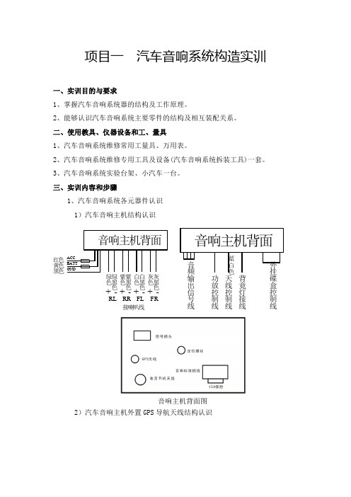
项目一 汽车音响系统构造实训一、实训目的与要求1、掌握汽车音响系统器的结构及工作原理。
2、能够认识汽车音响系统主要零件的结构及相互装配关系。
二、使用教具、仪器设备和工、量具 1、汽车音响系统维修常用工量具、万用表。
2、汽车音响系统维修专用工具及设备(汽车音响系统拆装工具)一套。
3、汽车音响系统实验台架、小汽车一台。
三、实训内容和步骤1、汽车音响系统各元器件认识 1)汽车音响主机结构认识音响主机背面图2)汽车音响主机外置GPS 导航天线结构认识直接连接于音响主机背面的GPS天线插孔上,接收天空上的GPS信号。
3)汽车音响高音喇叭结构认识连接于音响主机左右前置喇叭线上,高音喇叭连接线上串联有降低低频信号的电容器,让高音喇叭只发出高音音频,防止低频信号损坏高音喇叭。
4)汽车音响前门喇叭结构认识前门喇叭采用4寸先锋同轴喇叭,连接于音响主机左右前置喇叭线上,和两个高音喇叭并联输出信号。
5)汽车音响后门喇叭结构认识后门喇叭采用6×9寸先锋同轴喇叭,连接于音响主机左右后置喇叭线上,提供一定的低音输出信号。
6)汽车功放结构认识汽车功放接线汽车功放低音炮接线汽车功放按图装接,电源连接到蓄电池上,控制线连接到音响主机的功放控制线上。
其中低音喇叭只连接一只,功放只是利用了一半的输出功率,并且采用了BTL大功率接法;当音响主机关机状态时,功放指示灯为橙色,功放处于待机状态;当音响主机打开后,功放控制线输出12V控制电压给功放,功放指示灯转换成绿色,表示功放处于正常工作状态。
7)汽车低音喇叭结构认识低音喇叭采用12寸先锋低音炮,连接于功放输出端,主要是输出重低音响度。
8)汽车车载收音机自动天线结构认识车载收音机自动天线在音响主机打开时自动伸出,当关闭音响主机时自动缩回去,三条线连接,电源和搭铁,另一条是控制线,由音响主机打开输出12V 控制电压,控制天线伸出。
9)汽车音响保险胆结构认识汽车音响供电由蓄电池经这个保险胆供电,当音响系统有短路事故,保险胆自动烧断,保护线路。
- 1、下载文档前请自行甄别文档内容的完整性,平台不提供额外的编辑、内容补充、找答案等附加服务。
- 2、"仅部分预览"的文档,不可在线预览部分如存在完整性等问题,可反馈申请退款(可完整预览的文档不适用该条件!)。
- 3、如文档侵犯您的权益,请联系客服反馈,我们会尽快为您处理(人工客服工作时间:9:00-18:30)。
学员工作手册音响系统BMW 售后服务售后服务培训本工作手册中所包含的信息仅适用于BMW 售后服务培训班的学员。
有关技术数据方面的更改/ 补充情况请参见BMW 售后服务的最新相关信息。
信息状态:2005 年 6 月conceptinfo@bmw.de©2005 BMW 集团慕尼黑,德国。
未经BMW 集团(慕尼黑)的书面许可不得翻印本手册的任何部分。
VS-12 售后服务培训学员工作手册音响系统目录音响系统培训1 知识问答1培训车辆的音响组件3基础知识6收音机11放大器和扬声器16天线30外围设备32诊断:缺少天线信号36诊断:未对天线放大器供电37诊断:缺少NF 信号38诊断:收音机服务模式39学习目标检查48学员工作手册音响系统知识问答入学测验本章将检查有关音响系统主题的基础知识。
请在正确答案前打勾:1. 你是否通读过 SIP“IKT 基础”?¨是¨否2. 如何利用无线电波传输数据?¨导线连接¨通过光缆¨通过调制电磁波3. 通过 NF 信号使高频载波发生变化时称为什么?¨调制¨解调¨压缩¨减速4. 哪些因素可能影响收音机播放时的接收质量?¨天线长度¨天线类型¨使用天线多相择优装置¨天线的安装位置¨天线放大器的数量15. 以何种方式操作收音机?¨控制器¨收音机上的操作按钮¨组合开关¨方向盘¨电话6. BMW 车辆装有哪些音响系统?¨立体声音响¨ 4 声道 Quadro¨高保真音响¨7 声道MP3¨顶级高保真音响2培训车辆的音响组件有关所装组件的实际练习任务:确定所装组件及其安装位置:1. 在哪个车辆上进行练习?答案:E ______________2. 车上安装了哪种控制单元?¨ASK¨M-ASK¨CCC¨无记录安装位置:_____________________________________________________________________________3. 安装了哪种收音机系统?¨音频收音机¨BMW CD 收音机¨BMW Reverse¨Business 收音机¨Professional 收音机34. 安装了哪些驱动器?¨磁带驱动器¨CD 驱动器¨MD 驱动器¨DVD 驱动器¨CD 换碟机¨DVD 换碟机记录安装位置:____________________________________________________________________________________________________________________________________________________________________________________________________________________________________5. 安装了哪种音响系统?¨立体声音响¨高保真扬声器系统¨顶级高保真扬声器系统(Professional 高保真音响系统或 LOGIC 7)¨模拟附加放大器¨数字附加放大器6. 该车辆上装有多少个扬声器?____________________________________________________________________________7. 该车辆上装有哪些收音机天线?¨AM/FM 车顶天线¨AM/FM 后窗玻璃天线¨行李箱盖内的天线¨保险杠内的天线¨棒状天线¨记录安装位置:____________________________________________________________________________________________________________________________________________________________________________________________________________________________________48. 是否装有天线多相择优装置?¨是¨否如果“是”,请记录安装位置:_____________________________________________________________________________9. 是否装有卫星收音机SDARS?¨是¨否如果“是”,请记录安装位置:_____________________________________________________________________________基础知识HF 和 NF 信号路径音响系统可通过播放声音信号为驾驶员和乘员提供娱乐和信息。
在输入/ 输出示意图中展示了音频源至输出端的信号路径。
1 – E90 顶级高保真音响系统任务:请根据插图中的序号记录车内从接收无线电波至输出声波的信号路径。
在下表中记录相关组件和传输的信号类型:组件/ 控制单元信号类型5->6 后窗玻璃天线高频信号(HF)6->11->61->88->779->12->11->43->110->1单调谐器/ 双调谐器在收音机设备、M-ASK/CCC 和 AVT 内都可以安装以下某一种调谐器:l单调谐器l双调谐器。
单调谐器单调谐器用于接收音频信号,根据国家情况也用于接收RDS 信息。
单调谐器接收VHF、LW、MW 频率波段内的信号。
例如,广播电台发射的无线电波由后窗玻璃内的AM/FM 天线接收。
天线放大器(带有FM 天线多相择优模块)将接收到的HF 信号通过一个同轴电缆发送至调谐器。
双调谐器使用双调谐器时,信号也从天线经过天线放大器(带有多相择优模块)发送至双调谐器。
双调谐器由两个调谐器构成。
第一个调谐器是用于播放音频的AM/FM 调谐器。
第二个调谐器是作为搜索和数据接收器使用的FM 调谐器。
除VHF 波段外,第一个调谐器还可以接收LW、MW 和 SW(49 m 波段)波段以及美国天气预报波段内的信号。
音频调谐器接收所选广播电台节目和发出音乐信号时,数据调谐器在后台工作。
数据调谐器搜索广播电台覆盖范围内的其它信号。
例如,它会检测所选广播电台是否以另一个频率发送更强的信号(跟踪备选频率AF)。
如果出现这种情况,就会指示音频调谐器切换到更好的频率上。
数据调谐器接收与发射信号一起发射的附加TMC 数据(交通信息控制),并评估这些数据。
TMC 数据继续发送至导航系统,用于显示堵车情况和计算出绕行路线。
此外,即使用户正在收听AM 广播电台,数据调谐器也能接收并发出FM 交通公告。
数据调谐器编制一份所有可接收广播电台的列表。
此外还编制一份所有可接收交通广播电台的列表。
任务:请回答以下问题:1. 单调谐器可接收哪些波段/ 信息?¨LW¨MW¨SW¨VHF¨RDS/TMC2. 双调谐器内的第一个调谐器可接收哪些波段/ 信息?¨LW¨MW¨SW¨VHF¨RDS/TMC3. 双调谐器内的数据调谐器可接收哪些信息?¨LW¨MW¨SW¨VHF¨RDS/TMC音响系统的区别有三种音响系统:l立体声音响系统l高保真音响系统l顶级高保真音响系统。
这些音响系统的质量和放大器功率不同且所装扬声器的质量、功率和数量不同。
放大器安装在收音机本身内或一个附加控制单元内。
这些音响系统符合BMW 规定的音响标准。
音响标准包括:l划分为立体声、高保真和顶级高保真3 个音响系统l声场对称性l声压l立体声信号的线性。
立体声音响系统装有l低音扬声器和l宽带扬声器或l中音和高音扬声器。
高级音响系统使用l低音扬声器l中音扬声器l高音扬声器。
扬声器的安装位置取决于具体车辆和音响系统。
任务:请回答以下问题:1. 车辆上装有哪些音响系统?¨立体声音响¨高保真7¨LOGIC 7¨顶级高保真音响¨高保真音响2. 安装多个扬声器可达到什么效果?¨提高声压¨声场对称性¨减小放大器功率¨频率特性更线性化收音机波段收音机用于接收LW、MW、SW 和 VHF 波段内的广播电台节目。
除音频信息外,收音机还接收其它数据。
在此可接收在显示屏内显示的电台名称或用于导航系统的交通信息(通过RDS)。
波段频率下限频率上限应用信号类型LW 153 kHz 279 kHz 长波收音机MW 522 kHz 1710 kHz 中波收音机SW 5900 kHz 6250 kHz 短波收音机VHF 76 MHz 90 MHz 超短波收音机VHF 87.5 MHz 108 MHz 超短波收音机VHF 162.4 MHz 162.55 MHz 美规天气预报收音机S 波段2320 MHz 2332.5 MHz 数字收音机(美规)任务:为各波段分配所用调制方法并填入表格中:1 = 调幅(AM)2 = 调频(FM)3 = 数字编码收音机类型根据车辆情况,“收音机接收”功能由一个或多个控制单元执行。
收音机由以下模块组成l操作单元l显示单元l调谐器l放大器。
操作单元[B] 和显示单元 [A] 是用户与系统之间的联系界面。
调谐器[T] 负责调节广播电台和信号解调。
放大器[V] 用于将通过车内扬声器播出的音频信号放大。
操作单元 [B]调谐器 [T]放大器 [V]显示屏 [A] 2 – 收音机功能原理图索引说明1 在 Business CD 收音机(E83)或 Professional 收音机(E90)上操作单元、显示单元、调谐器和放大器模块安装在一个壳体内。
[B T V A]2 E83/E85 CID 收音机(Professional 导航系统)壳体内包括操作单元、调谐器和放大器模块。
显示单元(CID)模块单独安装。
[B T V] [A]3 在 E60 Business CD 收音机中调谐器和放大器模块集成在M-ASK 控制单元内。
操作单元(控制器)和显示单元(CID)模块分别单独安装。
