t5.4.O12
Tn5表达与纯化及对ZF4细胞DNA的酶活力测试

基因组学与应用生物学,2020年,第39卷,第10期,第4487 4490页研究报告Research ReportT n5表达与纯化及对Z F4细胞D N A的酶活力测试富伟康姜蓬垒刘玮韩兵社张俊芳‘上海海洋大学,中国科学技术部海洋生物科学国际联合研宄中心,水产科学国家级实验教学示范中心,水产种质资源发掘与利用教育部重点实 验室,上海,201306*通信作者,****************.cn摘要转座酶因其能够插入目的片段的能力正受到越来越多的关注,经过改造的高活性转座酶可用于标 记 D N A,具有较大的应用价值,如 A T A C-s e q(Assay for transposase-accessible chromatin using sequencing)以及 TrAC-looping(Transposase-mediated analysis of chromatin looping)等染色质高级结构捕获实验,使用高活性转座酶为染色质开放区D N A或存在染色质相互作用的片段加上标记,从而分离出目的片段。
天然转座酶 普遍活性较低,缺乏实际应用价值,而经过改造的高活性转座酶因其可能导致的致死突变,对宿主具有较大 毒性,难以制备。
本研究优化了高活性转座酶T n5的原核表达以及纯化方法,将己转化Petl5b His6T n5质粒 的改良型工程菌B L21-G o l d(D E3)以及毒性蛋白诱导条件进行原核表达,借助高活性转座酶T n5带有的His tag标签进行纯化,通过Western blotting鉴定了纯化所得蛋白,并使用考马斯亮蓝染色测定了目的蛋白浓 度,采取在标准反应条件下与斑马鱼Z F4细胞基因组D N A反应的方法,测试了纯化所得T n5的活性。
本研 究为进一步探测Z F4细胞基因组的三维结构提供了研究基础。
关键词转座酶,T n5,原核表达,蛋白质纯化,酶活性Expression, Purification and Enzyme Activity Test with ZF4 DNA of Tn5Fu Weikang Jiang Penglei Liu W e i H a n Bingshe Zhang Junfang*Key Laboratory of Exploration and Utilization of Aquatic Genetic Resources, National Demonstration Center for Experimental Fisheries Science Education, International Research Center for Marine Biosciences at Ministry of Science and Technology, Shanghai Ocean University, Shanghai, 201306************************************.cnDOI: 10.13417/j.gab.039.004487Abstract Transposase i s attracting more and more attention due to i t s ability to insert target fragments.Modified high-activity transposases can be used to label D N A and have great application value,such as A T A C-s e q(Assay for transposase-accessible chromatin using sequencing)and TrAC-looping (Transposase-mediated analysis of chromatin looping).In these experiments,transposase can be used to label D N A in the accessible region of chromatin or chromatin regions that interact with other chromatin to help isolating the target fragments.Natural transposases are generally low in activity and lack of practical application value;while modified high-activity transposases are highly toxic to the host and difficult to produce because of potential lethal mutation.In this study, w e optimized the prokaryotic expression and purification of high-activity transposase T n5.The modified engineering bacteria B L21-Gold(D E3) which has been transformed into pet15b His6T n5 plasmid and toxic protein induction conditions were used for prokaryotic expression,and the purified protein was purified by the His tag of the highly active transposase T n5.The purified protein was identified by Western blotting and determined by Coomassie brilliant blue staining Target protein concentration.The activity of purified T n5 was tested by digesting基金项目:本研宄由国家自然科学基金项目(31372516; 81770165)、上海市教育委员会“东方学者”计划支持项目、上海市自然科 学基金项目(13ZR1419500)和上海市人才发展资金项目(201457)共同资助引用格式:Fu W.K., Jiang P.L.,Liu W.,Han B.S.,and Zhang J.F.,2020, Expression, purification and enzyme activity test with ZF4 DNA of Tn5, Jiyinzuxue Yu Yingyong Shengwuxue (Genomics and Applied Biology), 39(10): 4487-4490 (富伟康,姜蓬鱼,刘玮,韩 兵社,张俊芳,2020, Tn5表达与纯化及对ZF4细胞D N A的酶活力测试,基因组学与应用生物学,39(10): 4487-4490)4488基因组学与应用生物学zebrafish Z F4 cell genomic D N A under standard reaction condition.This study provides a basis for further exploring the three-dimensional structure of Z F4 cell g e n o m e.K e y w o r d s Transposase,T n5,Prokaryotic expression,Protein purification,E n z y m e activity转座是基因组中一段D N A的移动,最早由M c-Climock(1929)在玉米中发现,是产生遗传多样性和 生物环境适应的重要机制。
弱酸、弱碱的解离常数表(精排打印版)

( K 2)
-2 -4
2.8×10 5.1×10
-2 -7
5.9×10⁻² 5.0×10 (K 1) 2.5×10 (K 2) 7.52×10 (K 1)
-3 -8
52
1,3,5-苯三甲酸
C6H3(COOH)3
15
磷 酸
H3PO4
6.31×10 (K 2) 4.4×10
-13 -2 -3 -7
( K 3)
3.0×10 (K 1) 16 焦磷酸 H4P2O7 4.4×10 (K 2) 2.5×10 (K 3) 5.6×10 17 18 19 20 21 22 23 24 25 氢硫酸 亚硫酸 硫 酸 硫代硫酸 氢硒酸 亚硒酸 硒 酸 硅 酸 亚碲酸 H2S H2SO3 H2SO4 H2S2O3 H2Se H2SeO3 H2SeO4 H2SiO3 H2TeO3
-13
3.6×10⁻⁴ 1.1×10 (K 1) 4.0×10 (K 2) 2.4×10 (K 1) 2.5×10 (K 2) 2.9×10 (K 1) 3.5×10 (K 2) 7.6×10 (K 1) 7.9×10 (K 2) 6.6×10 (K 3) 2.1×10 (K 1) 6.2×10 (K 2) 3.0×10 (K 3) 8.1×10 (K 4) 4.8×10 (K 5) 3.2×10 (K 6) 2.6×10 (K 1) 2.6×10 (K 2) 1.0×10 (K 1) 2.14×10 (K 2)
8 3.75 4.76 3.83 1.27 4.27 9.78 2.86 1.3 0.7 4.87 4.26 3.86 2.85 5.66 1.89 3.64 2.49 9.87 10.36 4.82 4.85 4.68 4.66 3.03 4.44 1.92 6.23 2.98 4.34 4.86 4.78 4.7 4.52 4.677 3.77 6.08 2.13 4.31 9.358 4.86 4.85 4.74 4.72 4.42 5.41 1 2 3 4 5 6 7 8 9 10 11 12 13 14 15 16 17 18 19 20 21 22 23 24 25 26 27 28 29 30 31 32 33 34 35 36
ST12宝钢标准

上海宝钢集团公司企业标准冷连轧低碳钢板及钢带Q/BQB 403-1999代替Q/BQB 403-971 范围本标准规定了冷连轧低碳钢板及钢带(以下简称为钢板及钢带)的尺寸、外形、重量、技术要求、试验方法、检验规则、包装、标志和质量证明书等。
本标准适用于上海宝钢集团公司冷轧部生产的冷连轧低碳钢板及钢带,这种产品主要用于冷变形加工和表面处理,但不作表面硬化、淬火或调质处理。
2 引用标准下列标准所包含的条文,通过在本标准引用而构成本标准的条文。
本标准发布时,所示版本均为有效。
所有标准都会被修订,使用本标准的各方应探讨使用下列标准最新版本的可能性。
GB 222-84 钢的化学分析用试样取样法及成品化学成分允许偏差GB 223 钢铁及合金化学分析方法GB 228-87 金属拉伸试验方法GB/T 230-91 金属洛氏硬度试验方法GB/T 1818-94 金属表面洛氏硬度试验方法GB 2975-82 钢材力学及工艺性能试验取样规定GB 4156-84 金属杯突试验方法(厚度0.2~2mm)GB 6397-86 金属拉伸试验试样EURONORM 49-72 无镀层冷连轧钢板的粗糙度测量Q/BQB 400-1999 冷连轧钢板及钢带的包装、标志及质量证明书Q/BQB 401-1999 冷连轧钢板及钢带的尺寸、外形、重量及允许偏差3 分类及代号3.1 钢板及钢带按用途区分如表1所示。
表 13.2 钢板及钢带按表面质量区分为二级:高级的精整表面 FC(即O5表面)较高级的精整表面 FB(即O3表面)注:O5、O3来源于德国标准DIN 1623部分1,字母O表示从德文字表面(Oberflache)的第1个字母而来。
3.3钢板及钢带按表面结构分为四种:特别平滑 b平滑 g无光泽 m粗糙 r3.4牌号为St14的钢板及钢带按拉延级别分为三级:用于冲制拉延最复杂的零件 ZF用于冲制拉延很复杂的零件 HF用于冲制拉延复杂的零件 F4尺寸、外形、重量4.1 St15钢板及钢带的公称厚度为1.0~2.0mm,St14-T的供货厚度为0.7~1.5mm,其他尺寸及尺寸允许偏差、外形、重量应符合Q/BQB 401的规定。
中考化学专题测试 专题09 有关化学式的计算(解析版)

有关化学式的计算一、单选题1.维生素A的化学名为视黄醇,是最早被发现的维生素。
其化学式为C20H30O,下列有关说法正确的是( )A.维生素A属于有机高分子化合物 B.维生素A中含有碳、氢、氧三中原子C.维生素A中氢元素的质量分数最大 D.维生素A分子中含有51个原子【答案】B2.乙酸(CH3COOH)又名醋酸,下列有关说法正确的是( )A.乙酸是食醋的主要成分 B.CH3COOH中C、H、O元素的质量比是2:4:2C.乙酸不能溶于水 D.CH3COOH中C元素的质量分数是【答案】A【解析】A、乙酸是食醋的主要成分,正确;B、CH3COOH中C、H、O原子的个数比为2:4:2,故质量比一定不是2:4:2,错误;C、乙酸易溶于水,错误;D、CH3COOH中C元素的质量分数=,错误。
故选A。
3.阿司匹林的主要成分是乙酰水杨酸(化学式C9H8O4),是治疗心血管疾病的重要药物之一。
下列关于乙酰水杨酸的说法错误的是( )A.一个乙酰水杨酸分子中原子总个数为21 B.乙酰水杨酸的相对分子质量为180C.乙酰水杨酸属于有机物 D.乙酰水杨酸中氢元素与氧元素的质量比为2:1【答案】D【解析】A.一个乙酰水杨酸分子中原子总个数为9+8+4=21,正确;B.乙酰水杨酸的相对分子质量为12×9+1×8+16×4=180,正确;C.乙酰水杨酸属于有机物,正确;D.乙酰水杨酸中氢元素与氧元素的质量比为(1×8):(16×4)=1:8,错误。
故选D。
4.葡萄糖酸钙常用于预防和治疗钙缺乏症,其化学式为Ca(C6H11O7)2,下列有关葡萄糖酸钙的说法正确的是A.葡萄糖酸钙属于氧化物 B.葡萄糖酸钙的相对分子质量为235C.葡萄糖酸钙由钙、碳、氧、氢四种元素组成 D.葡萄糖酸钙中葡萄糖酸根(C6H11O7)化合价为-2 【答案】C5.抗病毒处方药磷酸奥可他韦能够有效治疗甲型和乙型流感,分子式为C16H28N2O4•H3PO4下列说法正确的是()A.分子式中含7种元素 B.C16H28N2O4中C、O元素的质量比为4:1C.H3PO4由3个氢原子、1个磷原子、4个氧原子构成的D.H3PO4和H2SO4的相对分子质量相同【答案】D【解析】A、该物质是由碳、氢、氮、氧、磷五种元素组成的,错误;B、C16H28N2O4中C、O元素的质量比为(12×16):(16×4)=3:1,错误;C、一个H3PO4分子由3个氢原子、1个磷原子、4个氧原子构成的,错误;D、H3PO4的相对分子质量为1×3+31+16×4=98,H2SO4的相对分子质量为1×2+32+16×4=98,正确。
液压过度接头和软管接头O形圈

Q/SGD 谷登工程机械装备有限公司试用文件Q/SGD 8001-2011(试用版) 液压过度接头和软管接头O形圈2011-05-24 制订2011-05-28实施江苏谷登工程机械装备有限公司研发部(制订)前言根据公司现有产品常用的过渡接头和软管接头配用O形圈,特制定此文件。
本文件作为过渡接头检验和软管接头配用O形圈的依据。
本文件2011年5月24日首次制定,于2011年5月28日实施。
1范围规定本公司过度接头的尺寸、标记及技术要求和软管接头配用O形圈。
2 引用文件GB/T 3733-2008 卡套式端直通管接头GB/T 3765-2008 卡套式管接头技术条件永华过度接头样本(2004.7)永华软管总成/软管接头样本(2004.7)GB/T 7939—2008《液压软管总成试验方法》3扣压式软管接头型号及其配用O形圈表1轻型接头及其配用O形圈表2重型接头及其配用O形圈注: 1.表中代号用于编织软管。
2.如用于缠绕软管代号为20412-XX-XX 。
表3法兰夹使用螺杆、O形圈一览表表4螺纹紧固扭矩表4 过度接头1.外形结构管接头形式于尺寸应符合相应标准要求。
标准中未规定的结构尺寸由制造商确定,但应尽量减少流体阻力。
2.尺寸标准中规定的尺寸是指包括镀层或表面处理厚度在内的成品尺寸,所有未标注尺寸公差应为±0.4mm,接头端24°内锥座对其内螺纹中径的圆跳动公差应为0.25mm,柱端螺纹中径对密封端面的垂直度公差应为0.10mm。
3.通道公差接头体通道从两头加工时,汇合点的不重合偏差不得大于0.4mm,交叉通道的交汇横截面积不得低于规定的最小通道截面积。
4.角度公差规格不大于10mm的弯通、三通、和四通的端口轴线的角度公差应符合±2.5°,规格大于10mm的弯通、三通、和四通的端口轴线的角度公差应符合±1.5°。
5.螺纹5.1普通螺纹应符合GB/T193的规定,外螺纹公差应符合GB/T197的6g级规定,内螺纹公差应符合GB/T197的6H规定,螺纹收尾、肩距、退刀槽应符合GB/T3的规定。
TPCR系列硬币投币计时器与硬币总计器及计时器说明书
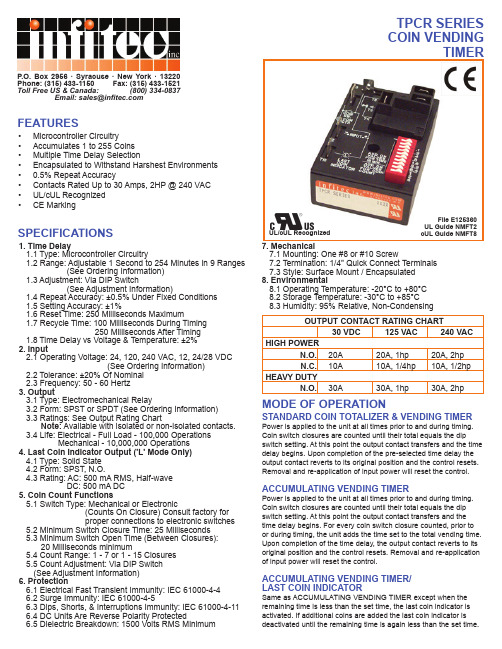
TPCR SERIES COIN VENDINGTIMERSTANDARD COIN TOTALIZER & VENDING TIMERPower is applied to the unit at all times prior to and during timing.Coin switch closures are counted until their total equals the dipswitch setting. At this point the output contact transfers and the time delay begins. Upon completion of the pre-selected time delay the output contact reverts to its original position and the control resets. Removal and re-application of input power will reset the control.ACCUMULATING VENDING TIMERPower is applied to the unit at all times prior to and during timing. Coin switch closures are counted until their total equals the dip switch setting. At this point the output contact transfers and the time delay begins. For every coin switch closure counted, prior to or during timing, the unit adds the time set to the total vending time. Upon completion of the time delay, the output contact reverts to its original position and the control resets. Removal and re-application of input power will reset the control.ACCUMULATING VENDING TIMER/LAST COIN INDICATORSame as ACCUMULATING VENDING TIMER except when the remaining time is less than the set time, the last coin indicator is activated. If additional coins are added the last coin indicator is deactivated until the remaining time is again less than the set time.P .O. Box 2956 · Syracuse · New York · 13220Phone: (315) 433-1150 Fax: (315) 433-1521Toll Free US & Canada: (800) 334-0837Email:*****************UL/cUL RecognizedFile E125360UL Guide NMFT2cUL Guide NMFT8FEATURESSPECIFICATIONSMODE OF OPERATION• Microcontroller Circuitry • Accumulates 1 to 255 Coins • Multiple Time Delay Selection• Encapsulated to Withstand Harshest Environments • 0.5% Repeat Accuracy• Contacts Rated Up to 30 Amps, 2HP @ 240 VAC • UL/cUL Recognized •CE Marking1. Time Delay1.1 Type: Microcontroller Circuitry1.2 Range: Adjustable 1 Second to 254 Minutes in 9 Ranges(See Ordering Information)1.3 Adjustment: Via DIP Switch(See Adjustment Information)1.4 Repeat Accuracy: ±0.5% Under Fixed Conditions 1.5 Setting Accuracy: ±1%1.6 Reset Time: 250 Milliseconds Maximum1.7 Recycle Time: 100 Milliseconds During Timing250 Milliseconds After Timing1.8 Time Delay vs Voltage & Temperature: ±2%2. Input2.1 Operating Voltage: 24, 120, 240 VAC, 12, 24/28 VDC(See Ordering Information)2.2 Tolerance: ±20% Of Nominal 2.3 Frequency: 50 - 60 Hertz3. Output3.1 Type: Electromechanical Relay3.2 Form: SPST or SPDT (See Ordering Information)3.3 Ratings: See Output Rating ChartNote: Available with isolated or non-isolated contacts.3.4 Life: Electrical - Full Load - 100,000 OperationsMechanical - 10,000,000 Operations4. Last Coin Indicator Output ('L' Mode Only)4.1 Type: Solid State 4.2 Form: SPST, N.O.4.3 Rating: AC: 500 mA RMS, Half-waveDC: 500 mA DC5. Coin Count Functions5.1 Switch Type: Mechanical or Electronic(Counts On Closure) Consult factory for proper connections to electronic switches5.2 Minimum Switch Closure Time: 25 Milliseconds 5.3 Minimum Switch Open Time (Between Closures):20 Milliseconds minimum5.4 Count Range: 1 - 7 or 1 - 15 Closures 5.5 Count Adjustment: Via DIP Switch (See Adjustment Information)6. Protection6.1 Electrical Fast Transient Immunity: IEC 61000-4-46.2 Surge Immunity: IEC 61000-4-56.3 Dips, Shorts, & Interruptions Immunity: IEC 61000-4-116.4 DC Units Are Reverse Polarity Protected6.5 Dielectric Breakdown: 1500 Volts RMS MinimumOUTPUT CONTACT RATING CHART30 VDC 125 VAC 240 VACHIGH POWERN.O.20A 20A, 1hp 20A, 2hp N.C.10A 10A, 1/4hp 10A, 1/2hpHEAVY DUTYN.O.30A 30A, 1hp 30A, 2hp7. Mechanical7.1 Mounting: One #8 or #10 Screw7.2 Termination: 1/4" Quick Connect Terminals 7.3 Style: Surface Mount / Encapsulated 8. Environmental8.1 Operating Temperature: -20°C to +80°C 8.2 Storage Temperature: -30°C to +85°C 8.3 Humidity: 95% Relative, Non-Condensing。
【国家标准】DB11T 1180-2015 清洁生产评价指标体系 汽车整车制造业
#
3 /012
#$ #
;
3.1
cleaner production
)()K*+TH ()8Z, H -*8aCS +YHK.ZBH/ 0 1S023 4a 0M#5/ "604+789:*+H;<+! =?]a ^8+* MN0>4`78 ?% @AB[J8[C;
56 planting P; QRSTUVKW9WXH<Y7Z[Z;O8=?; 3.5
789 indicators for pollutants generation VW+!*+17\a5=?]0+*a ^8U1]^AB 5; 3.6
:1* restrictive indicators
. U
*()*+
6 ()* +ZB
2 mg/m3
3 GB/T 27630
2 ()- F
L/100km 1 6 GB 19578HGB 20997 8D U
%*+=?] %*+=?]
8[J* 8TU[J
3 -09
*3 -09
%& GB/T24001 H 8= ?0 = ?0H
$ R$ 60, 805
* +YH*
+aC 3
2 )& _D?@ 8+YHaC
1 #"HZ 8
1 + ?!"7?!#$0%X9D&8&!FD'
; ; ()+S
1 ()*+X,+S1-./0VH1 /0V05
5.4.1 正弦函数、余弦函数的图象(课件)高一数学(人教A版2019必修第一册) (2)

图象向左平移
2
2
个单位长度而得到, 所以, 将正弦函数的图象向左平移
个单位长度, 就得到余弦函数的图象.
余弦函数y=cosx(x ∈R)的图象
sin(
x+ 2
)= cosx
y
余弦曲线 正弦曲线
x
-2
-
o
2
3
2
3
4
2
余弦函数的图象可以通过将正弦曲线向左
平行移动/2个单位长度而得到
足够多的点T ( x0 ,sin x0 ), 将这些点用光滑的曲线连接起来 , 可得到比
较精确的函数y sin x , x [0, 2 ]的图象(图5.4 3)
2
3
5
6
2
3
6
7
6
y
1
2
4
3
3
2
5
3
y=sinx ( x ∈ [0, 2 ] )
●
1
●
0
6
7 4 3 5 11
【变式 2】
求函数 f(x)=lg sin x+ 16-x2的定义域.
sin x>0,
解析:由题意,得 x 满足不等式组
2
16-x ≥0,
-4≤x≤4,
即
作出 y=sin x 的图象,如图所示.
sin x>0,
结合图象可得:x∈[-4,-π)∪(0,π).
【变式3】若函数f(x)=sin x-2m-1,x∈[0,2π]有两个零点,求m的取值范围.
图.这种近似的“五点(画图〉法”是非常实用的.
正弦函数的“五点画图法”
EPM1270T144I5中文资料(Altera)中文数据手册「EasyDatasheet - 矽搜」

f
有关等效宏单元详细信息,请参阅
宏单元转换方法
白皮书.
MAX II逻辑元素
MAX II和MAX IIG器件有三种速度等级:-3,-4,-5,与
-3是最快.同样,MAX IIZ器件有三种速度等级可供选择:-6,
-7,和-8,以-6是最快.这些速度等级代表总体相对
性能,而不是任何特定时序参数.对于传播延迟定时
2006年12月, 1.6版 2006年8月, 1.5版 2006年7月, 1.4版
■ 更新 表1-2.
■ 更新"简介"一节. ■ 更新新文档格式. ■ 通过表1-5更新表1-1. ■ 增加"参考文献"部分. ■ 添加文档修订历史记录.
■ 次要更新功能列表.
■ 次要更新表.
更改摘要
增加信息速度等级-8 —
在256引脚EPM570,EPM1270和EPM2210设备之间迁移
FineLine BGA封装).垂直迁移意味着你可以迁移到设备
其专用引脚和JTAG引脚是相同电源引脚子集或
超集跨设备密度一个给定包.在任何最大密度
包具有最高数量电源引脚;你必须制定出最大
在一个包计划密度以提供必要电源引脚进行迁移.供
EPM 2210 EPM 2210G
2,210 1,700 1,270 to 2,210 8,192 272
7.0 304 1.2 4.6
EPM 240Z 240 192
128至240 8,192 80 7.5 152 2.3 6.5
EPM 570Z 570 440
240至570 8,192 160 9.0 152 2.2 6.7
100-Pin FineLine
BGA
5.4.2正弦函数余弦函数的性质(第2课时)课件-高一上学期数学人教A版2

当堂达标
2.函数 f(x)= 3sin2x-π4,x∈R 的最小正周期为(
)
π A.2
B.π
C.2π
D.4π
【解析】 因为 3sin12x+4π-π4= 3sin12x-π4+2π = 3sin12x-π4,即 f(x+4π)=f(x),所以函数 f(x)的最小正周期为 4π.
当堂达标
3.函数 f(x)=sinx+π6的一个递减区间是(
(1)cos 150°与 cos 170°;(2)sin 5π与 sin-75π. 【解】 (1)因为 90°<150°<170°<180°,函数 y=cos x 在区间[90°,180°]
上是减函数,所以 cos 150°>cos 170°.
(2)sin-75π=sin-2π+35π=sin 35π=sinπ-25π=sin 25π.因为 0<π5<25π<π2,
)
A.-π2,π2
B.[-π,0]
C.-23π,23π
D.π2,23π
【解析】 令 x+π6∈π2+2kπ,32π+2kπ,k∈Z,
得 x∈π3+2kπ,43π+2kπ,k∈Z,
k=0 时,区间π3,43π是函数 f(x)的一个单调递减区间,
而π2,23π⊆π3,43π.故选 D.
当堂达标
4.比较下列各组数的大小:
函数 y=sin x 在区间0,π2上是增函数,
所以 sin
π 5<sin
25π,即 sin
π5<sin-75π.
课堂小结
正弦、余弦函数的奇偶性、单调性
函数
奇偶性
正弦函数 奇函数
余弦函数 偶函数
单调性(单调区间)
tPad中文使用手册

11目录第1章.tPad 简介 (3)1.1 关于tPad 套件............................................................................................................................................7 1.2 获取帮助 (8)第2章. tPad 概述 (9)2.1 布局和组件...............................................................................................................................................9 2.2 tPad 系统框图. (10)第3章. 使用 tPad (11)3.1 配置 Cyclone IV E FPGA 芯片...............................................................................................................11 3.2 总线控制器.............................................................................................................................................14 3.3 使用 8英寸LCD 触摸屏模块..................................................................................................................15 3.4 使用 500万像素数字影像传感器模块.. (16)第4章. tPad 设计范例 (18)4.1 系统要求.................................................................................................................................................18 4.2 出厂配置.................................................................................................................................................18 4.3 tPad Starter 设计范例..............................................................................................................................19 4.4 tPad 图片查看器.....................................................................................................................................23 4.5 视频与图像处理.....................................................................................................................................26 4.6 tPad 摄像头应用.....................................................................................................................................29 4.7 使用摄像头的视频与图像处理. (32)第5章. 应用选择器 (36)5.1 即刻可用的SD 卡演示范例....................................................................................................................36 5.2 运行应用选择器.....................................................................................................................................37 5.3 应用选择器详解.....................................................................................................................................37 5.4 恢复出厂默认程序 (40)2第6章. 附录 (43)6.1 修改历史.................................................................................................................................................43 6.2 版权声明. (43)第1章.tPad 简介tPad 高阶多媒体嵌入式系统开发套件为嵌入式开发人员创建多媒体系统提供了一个非常全面的设计环境。
V54C3256164VBS中文资料
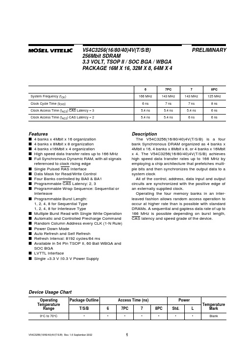
Operating the four memory banks in an interleaved fashion allows random access operation to occur at higher rate than is possible with standard DRAMs. A sequential and gapless data rate of up to 166 MHz is possible depending on burst length, CAS latency and speed grade of the device.
referenced to clock rising edge ■ Single Pulsed RAS Interface ■ Data Mask for Read/Write Control ■ Four Banks controlled by BA0 & BA1 ■ Programmable CAS Latency: 2, 3 ■ Programmable Wrap Sequence: Sequential or
TSOP TSOP TSOP
WBGA WBGA WBGA
SOC BGA SOC BGA SOC BGA
V54C3256(16/80/40)4V(T/S/B) Rev. 1.6 September 2002
2
元器件交易网
MOSEL VITELIC
电子物料编码规则

文件编号: 制/修订日期:重庆瓯福安电子有限公司本次: A-01物料编码规则订制:_____审核:_____批准:_____目录一、目的 .........................................................................二、造用范围 .....................................................................三、物料编码的基本运作程序 ......................................................四、物料编号规则 .................................................................五、编号规则说明 ................................................................5.1电阻器Resistor ..........................................................................5.2电容器Capacitor .........................................................................5.3电感器In ductor ..........................................................................5.4半导体器件Semic on ductor .............................................................5.5晶振OSC ..................................................................................5.6显示器件Dispaly ........................................................................5.7开关Switch On-Off .......................................................................5.8插座JACK .................................................................................5.9五金件Metal ...............................................................................5.10线Wire ..................................................................................5.11包装材料Packaging .....................................................................5.12辅助材料..................................................................、目的随着我公司规模的不断扩大 , 物料的品种越来越多 , 为了便于物料管理以及公司运作体系的不断完善。
液压气动用O形橡胶密封圈

液压气动用O形橡胶密封圈沟槽尺寸1 范围GB/T 3452的本部分规定了液压气动一般应用的O橡胶密封圈(以下简称O圈)的沟槽尺寸和公差。
GB/T 3452的本部分适用于GB/T 3452.1-2005《液压气动用O橡胶密封圈尺寸系列及公差》规定的O。
工作压力超过10 MPa时,需采用带挡圈的结构型式。
注,特殊应用的O圈沟槽尺寸应由O圈的制造商和使用者协商确定。
2 规范性引用文件下列文件中的条款通过GB/T 3452本部分的引用而成为本部分的条款。
凡是注日期的引用文件,其随后所有的修改单(不包括勘误的内容)或修订版均不适用于本部分,然而,鼓励根据本部分达成协议的各方研究是否可使用这些文件的最新版本。
凡是不注日期的引用文件,其最新版本适用于本部分。
GB/T 3452.1-005 液压气动用O形橡胶密封圈尺寸系列及公差GB/T 17446 流体传动系统和元件术语(GB/T 17446-1998,idt ISO5598:1985)3 术语、定义和字母符号GB/T 17446确定的术语和定义适用于本部分。
本部分采用下列字母符号:d1——O内径;d2——O形圈截面直径;d3——话塞密封的沟槽槽底直径;d4——缸内径;d5——活塞杆直径;d6——活塞杆密封的沟槽槽底直径;d7——轴向密封的沟槽外径(受内压);d8——轴向密封的沟槽内径(受外压);d9——活塞直径(活塞密封);d10——活塞杆配合孔直径(活塞杆密封);b——O形圈沟槽宽度(无挡圈);b1——加一个挡圈时的O形圈沟槽宽度;b2加两个挡圈时的O形圈沟槽宽度;h——轴向密封的O形圈沟槽深度;t——径向密封的O形圈沟槽深度;z——导角长度;r1——槽底圆角半径;r2——槽棱圆角半径;g——单边径向间隙。
4 O形圈沟槽型式根据O形圈压缩方向,O形圈沟槽型式分为径向密封和轴向密封两种。
4.1 径向密封4.1.1 活塞密封沟槽活塞密封沟槽型式应符合图l的规定。
微波技术基础课后答案 李秀萍版

Z 22 Z11 Z12 Z 21 (1 Z )( Z 1) Z 2 1 0 0 0 [S ] Z11 Z 22 Z12 Z 21 2Z12 (1 )(1 ) Z0 Z0 Z 02 Z0
将(1)式所得的阻抗矩阵 Z 导入即可。 (3)
Z11 Z 22 Z12 Z 21 (1 )( 1) Z0 Z0 Z 02 2Z12 Z0
解 2: d2 4.14
(1) 解 1: l1
解 2: l1
(2) 解 1: l1 解 2: l1 (3) 解 1: l1 解 2: l1 (4)
0.14 和 l2 0.07 0.25 和 l2 0.43 0.36 和 l2 0.41 0.14 和 l2 0.33
4.8
in
(1) (2) (3)
=r 7.33
Zin (5.4 j3.68) 100 (540 j368)
l 10 360 36
4.9 4.11
Z L (252 j105)
(1)
L
0.291e- j 30
2. 6
o
(2)
(3) Zin (4) Yl (5) Yin (6) Zl (7) Z l
Z0 100 j = =25.82 Y0 0.15 j
= Z 0Y0 -15=3.87 j
3.17
Z0 66.7
或 Z0
+
150
-
(1).V 0 10V , V 0 5 5 j V
3.18 (1)
V 5 2 1-j V ,V 5 2V 8 8 (2).V 0 15-5jV , V 5 2 2-j V 8
抛体运动的规律——平抛运动与圆相结合 高一下学期物理人教版(2019)必修第二册

3.如图所示,滑道ABC为四分之一圆弧,半径为2m,O为其圆心,C为圆弧最低
点,与地面相切,在和O点等高的某位置水平抛出一个小球,垂直击中圆弧上的B
点。弧AB的长度是弧BC的长度的2倍。忽略空气阻力,g取10m/s2,则抛出点与O
点水平距离是( A )
A.1m
首先要突出说明的是选题的现实价值,
2.如图所示为一半球形的坑,坑边缘上M、N两点与圆心等高且在同一竖直面
内。两位同学分别在M、N两点,同时将甲、乙两小球分别以V1、V2的速度沿图
示方向水平抛出,发现两球刚好落在坑壁上Q点,Q、Q’是半球上的两个对称点
(如图),已知 MOQ 60,忽略空气阻力首,先下要列突出说说法明的中是正选确题的的现是实价(值,ACD )
每一个研究的目的都是为了指导现实
生 么
活, 实际
一定 作用
要讲 、解
清 决本 什B选 么.题 问c的 题os研 ;α究 其有 次
什 再
写课题的理论和学术价值。
C tan tan
.
D cos cos
.
解:两小球被抛出后都做平抛运动,设容器的半径为R,两小球运动的时间
分别为t1、t2。则对球1有 Rsinα=v1t1 对球2有
15 3
7.如图所示,同一竖直平面内有四分之一圆环 BC 和倾角为53度的斜面 AC ,A 、
B两点与圆环BC的圆心O 等高。现将甲、乙小球分别从 、 两点以初速度 V1、V2
沿水平方向同时抛出,两球恰好在C 点相碰(不计空气阻力),已知 sin53 0.8,
cos53 0.6 下列说法正确的是( AD )
根据几何关系可得
COB 60
铋基材料的发展综述

环境友好型铋基材料的制备及其性能研究1 概述能源危机和环境问题的日益加重已成为影响全人类可持续发展的重要问题。
近年来,可再生与不可再生资源日益枯竭,使得人们不得不高度重视排放物、废弃物的妥善处理和循环再生,减少不可再生资源的消耗和环境的污染,同时寻求绿色环保、可持续发展的新能源就逐渐受到世界各国的广泛关注。
光催化实际上是光催化剂在某些波长光子能量的驱动下,体内的空穴电子对分离,后又引发了一系列氧化还原反应的过程。
光催化氧化技术由于其具有环境友好,能有效去除环境中尤其是废水中的污染物,且能耗少,无二次污染等优点已被慢慢重视起来。
自1972 年Fujishima等[1]在《Nature》报道了TiO2在紫外光照射下可以催化水的分解后,半导体光催化剂一直是广大学者们研究的热点。
光催化被认为是解决能源问题的关键有效方法之一,近年来受到广大研究者的不断探究。
为了充分利用太阳光,人们对光催化材料进行了众多研究:一方面是对TiO2半导体进行改性,另一方面是寻求新型的非TiO2半导体光催化材料。
含铋光催化材料属于非TiO2半导体光催化材料中的一种,电子结构独特,价带由Bi-6s和O-2p轨道杂化而成。
这种独特的结构使其在可见光范围内有较陡峭的吸收边,阴阳离子间的反键作用更有利于空穴的形成与流动,使得光催化反应更容易进行。
本文将对近年来含铋光催化剂的研究进展进行综述。
2 铋类光催化剂的制备2.1铋氧化物光催化剂铋氧化物是很重要的功能材料,在光电转化、医药制药材料等方面有着很广泛的运用。
其中,纯相还具有折射率高、能量带隙低和电导率高的特点。
Bi 2O 3有单斜、四方、体立方和面立方四种结构,只有单斜结构室温下可稳定存在,其他结构在室温下均会转变成单斜结构。
化学沉积法、声化学方法、溶胶-凝胶法、微波加热法等都是制备纳米Bi 2O 3的方法。
产品的形态也可根据方法不同而不同,如颗粒状、薄膜状、纤维状等。
Wang 等[2] 利用沉积法合成钙铋酸盐(CaBi 6O 10/Bi 2O 3)复合光催化剂,在可见光下(波长大于420nm )降解亚甲基蓝,催化效果显著。
高性能混凝土桁架板常用型号及技术参数、产品出厂检验与型式检验、常用钢筋桁架钢筋规格

附录A高性能混凝土桁架板常用型号及技术参数A.0.1高性能混凝土桁架板常用型号及技术参数可按表AO1选用。
表A.0.1高性能混凝土桁架板常用型号及技术参数2、施工最大适用跨度中“无支撑”指不设置临时支撑的两端简支板情况,“中间支撑”指跨中设置一道临时支撑的两等跨连续板情况;当在三分之一跨设置两道支撑时,施工最大适用跨度13=1∣+1203、上、下弦钢筋采用HRB400,腹杆钢筋采用性能等同CRB550的冷轧钢筋。
如果上弦、下弦钢筋采用HRB500钢筋、HRB600钢筋、CRB600H钢筋,可直接进行等强度代换,并进行施工阶段验算。
4、钢筋桁架间距按20Omm计算,垂直于钢筋桁架方向上部钢筋位于钢筋桁架上弦钢筋下方。
5、柱边位置高性能混凝土桁架板需切角,钢筋桁架切掉时需做好支撑。
6、如果条件限制不能设置支撑,可按单向单跨简支板要求进行设计。
7、如果板厚超出表中所列型号范围,可按本规程有关要求进行设计确定。
附录B高性能混凝土桁架板产品出厂检验与型式检验8.1出厂检验8.1.1高性能混凝土桁架板应做出厂检验。
检验合格后应提供检验报告;产品质量合格后方可出厂。
8.1.2高性能混凝土桁架板检验组批与抽样规则应符合表B.1.2的规定。
8.1.3每批检验中,外观质量有不合格时,该批产品应逐件检查。
外观质量不合格产品经整修,并进行复验达到合格要求后方可出厂。
8.1.4每批焊点抗剪试验及连接节点抗拉承载力试验,如有一个试件不符合要求时,应加倍抽样进行复验。
复验结果仍有一个试件不符合要求,则该批产品应判定为不合格品。
8.2型式检验8.2.1有下列情况之一时应进行型式检验:1新产品或老产品转厂生产的试制定型鉴定;2生产中原材料、配合比、生产工艺改变,可能影响产品质量时;3出厂检验结果与上次型式检验结果有较大差异时;4产品停产达半年以上恢复生产时;5正常生产时,每36个月进行一次。
8.2.2型式检验项目、检验依据、检验数量及样品尺寸应符合表B.2.2的规定。
矿物的密度表
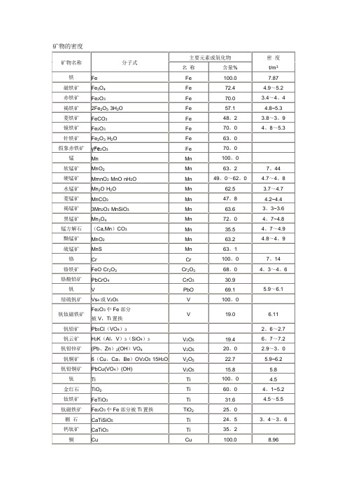
Pb2As2S6
Pb
55。4
6。23
硫铅镍矿
Ni3Pb2S2
Pb
57.0
5.5
硒铅矿
PbSe
Pb
63。3
8.85
钒铅矿
Pb5(VO4)3Cl
P
73.3
8.0~8.2
铅铁矾
PbFe6(SO4)4(OH)12
Pb
67.7
锌
Zn
Zn
18。3
闪锌矿
ZnS
Zn
100.0
7.1
菱锌矿
ZnCO3
Zn
67。0
5.6~5。7
角银矿
AgCl
Ag
75.3
5.5
硒铜银矿
AgCuSe
Ag,Cu
18.7
7。5
铂,钯
Pt,Pd
Pt,Pd
100。0
自然铂
Pt
Pt
70。0~96。0
14.0~19.0
砷酸铂矿
PtAs2
Pt
56。5
10.6
铋碲钯铂矿
(Pt、Pd)(Te、Bi)2
Pt
18.6~30。8
等轴铋碲钯矿
Pd(Te、Bi)2
Cu
55.3
3。7~3.8
硅孔雀石
CuSiO3·2H2O
Cu
57。5
3。7~4。1
氯铜矿
CuCl2·3Cu(OH)2
Cu
36。2
2~2。2
水胆矾
CuSO4·3Cu(OH)2
Cu
59.5
3。7~3。7
胆矾
CuSO4·5H2O
Cu
56。2
3.8~3。9
- 1、下载文档前请自行甄别文档内容的完整性,平台不提供额外的编辑、内容补充、找答案等附加服务。
- 2、"仅部分预览"的文档,不可在线预览部分如存在完整性等问题,可反馈申请退款(可完整预览的文档不适用该条件!)。
- 3、如文档侵犯您的权益,请联系客服反馈,我们会尽快为您处理(人工客服工作时间:9:00-18:30)。
EXPERIMENTAL INVESTIGATIONS ON SMALL LOW FLOW SDHW SYSTEMS BASEDON MANTLE TANKSSimon Furbo Department of Civil Engineering Technical University of Denmark Brovej, Building 118DK-2800 Kgs Lyngby, Denmarksf@byg.dtu.dkJianhua Fan Department of Civil Engineering Technical University of Denmark Brovej, Building 118DK-2800 Kgs Lyngby, Denmarkjif@byg.dtu.dkABSTRACTSide-by-side tests of two small SDHW systems based on mantle tanks have been carried out in a laboratory test facility. The systems are identical with exception of the vertical mantle tank. One of the tanks is the so-called Danlager 1000 marketed by Nilan A/S. The other tank is a test tank produced by METRO THERM A/S. Both tanks are built into 60 x 60 cm cabinets. In this way it is possible to bring the test tank on the market. Both hot water tanks have a total volume of 189 l and an auxiliary volume of 86 l at the top of the tank heated to 51°C by a 1000 W electrical heating element during the tests. The hot water tank diameter is 492 mm and 400 mm for the Danlager 1000 tank, respectively the test tank. The height/diameter ratio for the hot water tank is 2.1 for the Danlager 1000 tank and 3.9 for the test tank. The mantle inlet for the Danlager 1000 tank is located at the very top of the mantle, while the mantle inlet for the test tank is located 125 mm from the top of the mantle. Both tanks are insulated with PUR foam insulation filling up the space between the tanks and the cabinets. Consequently the insulation thickness for the test tank is greater than the insulation thickness of Danlager 1000.The tests were carried out with the same daily hot water consumption of 100 l/day. Measurements of the thermal performance of the systems have been carried out for more than one year. The measurements show that the thermal performance of a SDHW system can be increased by about 15% by replacing the marketed tank with the test tank.It is thus documented that marketed mantle tanks can be strongly improved by increasing the height/diameter ratio, by increasing the thickness of the side insulation and by lowering the position of the mantle inlet.1. INTRODUCTIONSmall solar domestic hot water systems based on vertical mantle tanks, as schematically shown in figure 1, have a number of advantages compared to similar solar domestic hot water systems based on hot water tanks with a built in heat exchanger spiral [1].The advantages are:The yearly thermal performance is increased by 10%-25% depending of the solar fraction. The increased thermal performance is caused by the thermal stratification established in the mantle tank during the operation of the solar collectors.Lime deposits in the mantle tank are a factor of 2.5 lower than the lime deposits in a similar hot water tank with a built in heat exchanger spiral. Sooner or later the lime deposits, which are located at the bottom of the tanks, will cover a part of the heat exchanger spiral resulting in a decreased heat exchange capacity rate, an increased collector temperature, a decreased collector efficiency and critical high solar collector fluid5 SOLAR THERMAL SYSTEMS AND APPLICATIONS2055temperatures. These problems will not occur in themantle tank.Fig. 1: Schematic illustration of SDHW system based on amantle tank.If low volume flow rates are used instead of highvolume flow rates in the solar collector loop the extra thermal performance of mantle tank systems can additionally be somewhat increased. Further, small pipe dimensions can be used in the solar collector loop if low flow rates are used. Therefore the installation can be facilitated. For instance, small all-in-one solutions with two small pipes, pipe insulation and a wire for the control system can be used as solar collector loops. In this way the cost of the solar heating system can be decreased and the thermal performance of the solar heating system can be further increased due to reduced heat loss from the pipes of the solar collector loop. The above mentioned good reasons to use mantle tanks as hot water tanks for small solar domestic hot water systems have been known for many years. Further, recent theoretical investigations showed that it is possible essentially to increase the thermal performance of low flow solar domestic hot water systems based on Danish marketed mantle tanks by relatively simple design changes of the tanks [2]. The thermal performance can be strongly improved by:Increasing the height/diameter ratio of the mantle tank Reducing the height of the mantleIncreasing the thickness of the insulation material onthe tank sidePlacing the mantle inlet at a level somewhat lower than the upper mantle levelUsing a tank material with a lower thermal conductivity than steel Of course it is of special interest that the thermal performance can be increased by reducing the mantle height. In this way it is possible to decrease the costs of mantle tanks.2. EXPERIMENTAL INVESTIGATIONSIn order to document that marketed mantle tanks can be improved as mentioned above, tests were carried out in a laboratory test facility for solar domestic hot water systems at the Technical University of Denmark. Two small low flow solar domestic hot water systems based on mantle tanks were tested side-by-side in the test facility. The systems are identical with exception of the mantle tanks. The most important data for the systems are shown in Table 1.TABLE 1: DATA FOR THE TWO TESTED SOLAR HEATING SYSTEMSSolar collector manufacturer Arcon Solvarme A/S Solar collector type ST-NA Solar collector area 2.51 m² Maximum collector efficiency 0.801Collector heat loss coefficients3,21 W/m²K and 0.013 W/m²K² Incidence angle modifier for collector 3.6 (tangent equation) Collector orientation South facing Collector tilt 45°Solar collector loop 33 m 10/8 mm copper pipes V olume flow rate in solar collector loop 0.5 l/minSolar collector fluid 40% propylene glycol/water mixtureLocationTechnical University of Denmark, Kgs. Lyngby, Denmark. Latitude: 56°NProceedings of ISES Solar World Congress 2007: Solar Energy and Human Settlement2056The hot water tanks used in the systems are the marketed vertical mantle tank Danlager 1000 from Nilan A/S and a vertical test mantle tank produced by METRO THERM A/S. Danlager 1000 is considered as the best hot water tank for small solar domestic hot water systems on the Danish market. Both tanks have a domestic water volume of 189 l and an auxiliary volume of 86 l at the top of the tanks. During the test period the auxiliary volumes are heated to 51°C of an electrical heating element with a power of 1000 W.For both mantle tanks the tank material is steel. Both tanks are built into a 60 x 60 cm cabinet. The height of the cabinet is 181 cm for Danlager 1000 and 197 cm for the test tank. Figure 2 shows a photo of the two tanks used in the investigations. The most important data for the twomantle tanks are shown in Table 2.Fig. 2: Photo of the two tanks used in the experiments. The test tank design is determined based on calculations with the detailed simulation program MANTLSIM [3]. MANTLSIM is used to calculate the thermal performance of solar domestic hot water systems with differently designed mantle tanks.The test tank has a smaller diameter than Danlager 1000 and correspondingly a higher height. The height/diameter ratio is 3.9 for the test tank and 2.1 for Danlager 1000. The thickness of the insulation material for the side of the tank is larger for the test tank than for Danlager 1000, since the space between the tank and the cabinet for both tanks are filled up with PUR foam. Finally, the mantle inlet for the test tank is placed 12.5 cm below the top of the mantle,while the mantle inlet for Danlager 1000 is placed at the top of the mantle.TABLE 2: DATA FOR THE TWO MANTLE TANKS OF THE SOLAR HEATING SYSTEMS TankDanlager 1000Test tank Outer diameter of hot water tank0.492 m 0.400 mHeight/diameter ratio of hot water tank 2.1 3.9 Mantle gap 0.0115 m 0.0200 m Mantle height0.395 m0.600 m Heat transfer area, mantle0.61 m² 0.75 m² Water volume above upper mantle level 97 l 110 l Mantle inletTop of mantle0.125 m from top of mantle Thickness of hot water tank wall0.0030 m 0.0025 m Thickness of mantle wall0.0025 m 0.0025 m3. MEASURED THERMAL PERFORMANCEThe two solar heating systems have been tested under the same test conditions in the test period March 12, 2006 – May 22, 2007: The solar radiation on the two collectors is the same and the hot water consumption and hot water consumption pattern are the same for both systems. Daily a hot water volume of 100 l, heated from 10°C to 50°C, is tapped from each tank. Hot water is drawn from the tanks at 7 am, at noon and at 7 pm in three equally sized volumes. The hot water consumption is 32.2 kWh per week. The tapped energy, the auxiliary energy and the solar heat transferred to the heat storage are measured for each system during the whole test period.The monitoring system had failures in some of the weeks during the test period. In the year May 08, 2006 – May 08, 2007 measurements of the thermal performance of the two systems were carried out in 40 weeks. Most of the weeks with failures of the monitoring system appear in the autumn 2006. The measured results for the 40 weeks are shown in5 SOLAR THERMAL SYSTEMS AND APPLICATIONS2057Table 3. The net utilized solar energy is the tapped energyminus the auxiliary energy transferred to the top of the tank by means of the electrical heating element. The solar fraction is the ratio between the net utilized solar energy and the tapped energy.TABLE 3: MEASURED ENERGY QUANTITIES IN 40 WEEKS IN THE TEST PERIOD MAY 08, 2006 - MAY 08, 2007Measured energySolar heating system with Danlager 1000 Solar heatingsystem with test tankSolar radiation on solar collector2270 kWh 2270 kWhTapped energy 1289 kWh 1289 kWhAuxiliary energyto top of tankfrom electricalheating element738 kWh 664 kWh Solar heat transferred to hotwater tank780 kWh 814 kWhNet utilized solar energy551 kWh625 kWhSolar fraction 43 % 49% It is seen that the thermal performance of the solar heatingsystem with the test tank in the 40 weeks test period is 13% higher than the thermal performance of the solar heating system based on Danlager 1000.Figure 3 shows the performance ratio, defined as the ratio between the net utilized solar energy for the solar heating system based on the test tank and the net utilized solar energy for the solar heating system based on Danlager 1000, as a function of the solar fraction for the solar heating system based on Danlager 1000. Each point in the figure represents the performance ratio for one week. For instance, a point with a solar fraction of 0.50 and a performance ratio of 1.20 corresponds to a week where the thermal performance of the solar heating system with the test tank is 20% higher than the thermal performance of the solar heating system with Danlager 1000 and where the solar heating system with Danlager 1000 covers half of the hot water consumption.Solar fraction of the system with Danlager 1000, [-]P e r f o r m a n c er a t i o [-] Fig. 3: Performance ratio for the solar heating system withthe test tank as a function of the solar fraction of the solar heating system with Danlager 1000. The extra thermal performance of the solar heating system with the test tank is strongly influenced by the solarfraction. The extra thermal performance is increasing for decreasing solar fraction. The thermal advantage of the test tank is therefore highest in the winter period, in less sunny periods of the year and in periods with a high hot water consumption. Based on the measurements it is estimated that the extra yearly thermal performance, without problems with the monitoring system, would be 15%. 4. CONCLUSIONSThe investigations have documented that relatively small design changes of a marketed mantle tank can result in relatively large increased thermal performance of a small solar domestic hot water system.It is recommended to design mantle tanks built into 60 x 60 cm cabinets with high height/diameter ratios, with increased side insulation thickness and with a mantle inlet position somewhat lower than the top of the mantle. Hopefully, improved mantle tanks will soon be brought onto the market.5. REFERENCES(1) S. Furbo, “Small Low Flow DHW Solar HeatingSystems - Status”, Thermal Insulation Laboratory,Proceedings of ISES Solar World Congress 2007: Solar Energy and Human Settlement 2058Technical University of Denmark, report no. 90-13, 1990.(2) S. Furbo & S. K nudsen, “Improved design of mantletanks for small low flow SDHW systems”, International Journal of Energy Research, vol: 30, Issue 12, pp. 955-965, 2006. (3) S. K nudsen, “Investigations and optimisation of heatstorage tanks for low flow SDHW systems”, report R-075. Department of Civil Engineering, Technical University of Denmark, 2004. Downloadable from www.byg.dtu.dk.。
