阿法拉伐LKH-35安装调整)
阿法拉伐垫片框式换热器操作手册说明书
Lit. Code200000419-4-ZH-CN操作手册中文由...出版阿法拉伐 Lund AB箱74参观:Rudeboksvägen 1226 55 Lund, 瑞典+46 46 36 65 00+46 46 30 50 90******************The original instructions are in English© Alfa Laval Corporate AB 2021-04本文件及其内容受阿法拉伐集团公司拥有的著作权及其他知识产权权利的保护。
未经阿法拉伐集团公司的事先明确书面许可,任何人不得以任何形式或通过任何方式,或出于任何目的,复制、重新制作或传输本文件的任何内容。
本文件所提供的信息和服务仅为用户提供便利和服务,对该信息和服务的准确性和适用性不做出于任何目的的陈述或保证。
保留所有权利。
EnglishDownload local language versions of this instruction manual from /gphe-manuals or use the QR codeбългарскиИзтеглете версиите на това ръководство заупотреба на местния език от / gphe-manuals или използвайте QR кода.ČeskýStáhněte si místní jazykovou verzi tohoto návodu k obsluze z /gphe-manuals nebo použijte QR kód.DanskHent lokale sprogversioner af denne brugervejledning på /gphe-manuals eller brug QR-koden.DeutschSie können die landessprachlichen Versionen dieses Handbuch von der Website /gphe-manuals oder über den QR-Code herunterladen.ελληνικάΠραγματοποιήστε λήψη εκδόσεων του παρόντοςεγχειριδίου οδηγιών σε τοπική γλώσσα από το/gphe-manuals ή χρησιμοποιήστετον κωδικό QR.EspañolDescárguese la versión de este Manual de instrucciones en su idioma local desde/gphe-manualso utilice el código QR.EestiSelle kasutusjuhendi kohaliku keele versiooni saate alla laadida lingilt /gphe-manuals või kasutades QR-koodi.SuomalainenLaitaa tämän käyttöohjeen suomenkielinen versio osoitteesta /gphe-manuals tai QR-koodilla.FrançaisTéléchargez des versions de ce manuel d’instructions en différentes langues sur /gphe-manuals ou utilisez le code QR.HrvatskiPreuzmite lokalne verzije jezika ovog korisničkog priručnika na poveznici /gphe-manuals ili upotrijebite QR kod.MagyarAz Ön nyelvére lefordított használati útmutatótletöltheti a /gphe-manuals weboldalról, vagy használja a QR-kódot.ItalianoScarica la versione in lingua locale del manuale di istruzioni da /gphe-manuals oppure utilizza il codice QR.日本の/gphe-manuals からご自分の言語の取扱説明書をダウンロードするか、QRコードをお使いください。
35 KV三相抗短路电容器更换套件安装说明书

35 kV three-phase bushing retrofit kit installation instructionsDISCLAIMER OF WARRANTIES AND LIMITATION OF LIABILITYThe information, recommendations, descriptions and safety notations in this document are based on Eaton Corporation’s (“Eaton”) experience and judgment and may not cover all contingencies. If further information is required, an Eaton sales office should be consulted. Sale of the product shown in this literature is subject to the terms and conditions outlined in appropriate Eaton selling policies or other contractual agreement between Eaton and the purchaser.THERE ARE NO UNDERSTANDINGS, AGREEMENTS, WARRANTIES, EXPRESSED OR IMPLIED, INCLUDING WARRANTIES OF FITNESS FOR A PARTICULAR PURPOSE OR MERCHANTABILITY, OTHER THAN THOSE SPECIFICALL Y SET OUT IN ANY EXISTING CONTRACT BETWEEN THE PARTIES. ANY SUCH CONTRACT STATES THE ENTIRE OBLIGATION OF EATON. THE CONTENTS OF THIS DOCUMENT SHALL NOT BECOME PART OF OR MODIFY ANY CONTRACT BETWEEN THE PARTIES. In no event will Eaton be responsible to the purchaser or user in contract, in tort (including negligence), strict liability or other-wise for any special, indirect, incidental or consequential damage or loss whatsoever, including but not limited to damage or loss of use of equipment, plant or power system, cost of capital, loss of power, additional expenses in the use of existing power facilities, or claims against the purchaser or user by its customers resulting from the use of the information, recommendations and descriptions contained herein. The information contained in this manual is subject to change without notice.ii35 KV CLASS THREE-PHASE BUSHING RETROFIT KIT INSTALLATION INSTRUCTIONS MN800005ENContentsSAFETY INFORMATIONSafety instructions (iv)PRODUCT INFORMATIONIntroduction (1)Acceptance and initial inspection (1)Handling and storage (1)Standards (1)INSTALLATION INSTRUCTIONS (2)iii35 KV CLASS THREE-PHASE BUSHING RETROFIT KIT INSTALLATION INSTRUCTIONS MN800005ENiv 35 KV CLASS THREE-PHASE BUSHING RETROFIT KIT INSTALLATION INSTRUCTIONS MN800005ENEaton meets or exceeds all applicable industry standards relating to product safety in its Cooper Power™ series products. We actively promote safe practices in the use and maintenance of our products through our service literature, instructional training programs, and the continuous efforts of all Eaton employees involved in product design, manufacture, marketing, and service.We strongly urge that you always follow all locally approved safety procedures and safety instructions when working around high voltage lines and equipment, and support our “Safety For Life” mission.Product informationIntroductionEaton provides instructions for removing the existing contact tube and gas valve from a 35 kV, 200 A three- phase rated Cooper Power™ series apparatus bushing and installing a new contact tube and gas valve.Read this manual firstRead and understand the contents of this manual and follow all locally approved procedures and safety practices before installing or operating this equipment.Additional informationThese instructions cannot cover all details or variationsin the equipment, procedures, or process described nor provide directions for meeting every possible contingency during installation, operation, or maintenance. For additional information, contact your Eaton representative.Acceptance and initial inspectionEach three-phase bushing retrofit kit is in good condition when accepted by the carrier for shipment. Upon receipt, inspect the shipping container for signs of damage. Unpack the three-phase bushing kit and inspect it thoroughly for damage incurred during shipment. If damage is discovered, file a claim with the carrier immediately.Handling and storageBe careful during handling and storage of the retrofit kit to minimize the possibility of damage. If the retrofit kit is to be stored for any length of time prior to installation, provide a clean, dry storage area.StandardsISO 9001 Certified Quality Management SystemFigure 1. Line illustration of three-phase apparatus bushing.135 KV CLASS THREE-PHASE BUSHING RETROFIT KIT INSTALLATION INSTRUCTIONS MN800005ENHigh Voltage. All associated apparatus must bede-energized during installation or maintenance. Failure to comply may result in death, severe personal injury, and equipment damage.Installation instructionsStep 1Remove the contact tube• Engage the driving blades of the contact tube removal wrench into two of the slots at the end of the contact tube. See Figure 2.• While applying pressure to the torque tool to prevent disengagement from the slots, rotate the contact tube counterclockwise. Approximately six revolutions will be required to remove contact tube.• Discard the contact tube.otee:N If you are not able to remove the contact tube, there are two possible causes:1. Contact tube slots are stripped and the wrench cannotbe engaged.2. The contract tube removal force required is so largethat the retainer pin securing the piston breaks. In this case, the contact rotates freely but doesn not back out. If either of these two items has occurred, the bushing will need to be replaced.Step 2Remove the gas valve• Remove the gas valve and valve spring from the bushing. If you cannot obtain the gas valve/spring, push valve back in and let the spring push it out to where you can grab it. See Figure 2.• Discard the gas valve.Gas ContacttubeO-ringFigure 2. Installation of contact spring/gas valve into busing.235 KV CLASS THREE-PHASE BUSHING RETROFIT KIT INSTALLATION INSTRUCTIONS MN800005ENStep 3Install the new gas valve• Assemble the O-Ring into the groove in the new gasvalve.• Lubricate the O-Ring with silicone grease.• Assemble the new gas valve onto the valve spring. Installthe valve spring/gas valve into the bushing. See Figure 2.otee:N Ensure the gas valve is engaged to the valve springafter installation.Step 4Install the new contact tube• Apply silicone grease to the O-ring on the contact tube.• Insert the contact tube partially into the bushing andengage the wrench into the slots at the end of thecontact tube.• Rotate the contact tube clockwise as you install it.Rotating the contact tube clockwise aids passage of theO-ring into the bushing.• Engage the threads of the contact tube into the threadsof the piston. Ensure the wrench is fully installed into theslots at the end of the contact tube. Torque the contacttube in to 15 ft-lbs.pin is broken and the bushing must be removed andreplaced. Dispose of the old bushing. Failure to complycould result in personal injury or equipment damage.335 KV CLASS THREE-PHASE BUSHING RETROFIT KIT INSTALLATION INSTRUCTIONS MN800005ENEaton1000 Eaton Boulevard Cleveland, OH 44122United StatesEaton’s Cooper Power Systems Division2300 Badger Drive Waukesha, WI 53188United States/cooperpowerseries© 2015 EatonAll Rights ReservedPrinted in USAPublication No. MN800005EN Rev 00 (Replaces S800391 Rev 1)Eaton is a registered trademark.All trademarks are propertyof their respective owners.For Eaton's Cooper Power series productinformation call 1-877-277-4636 or visit:/cooperpowerseries.。
WK-35调试报告__2010[1].12
![WK-35调试报告__2010[1].12](https://img.taocdn.com/s3/m/760855e5102de2bd96058843.png)
WK-35挖掘机电气调试手册一、调试前的准备1.检查所有的电气设备,对电子设备、PC、变频、调节器等严禁使用摇表;发现有异常现象,要分析原因及时处理;2.检查PLC控制柜、辅助控制柜、高压柜、切换柜、操作台、润滑室控制箱、变频柜以及各电气设备内接线是否正确,有无错线、漏线;3.检查电气柜内的接线端子有无接地或短路现象。
二、供电1.外部6kVAC 3φ+PE 50Hz通过高压集电环接入高压柜,合高压负荷开关Q021,辅助变压器送电;通过高压柜内相序继电器察看相序,指示灯为绿色,相序正确,否则为红色;2.合辅助柜内断路器Q023,给PLC电源模块、输入模块、输出模块送电;将程序下载到CPU模块;3.PLC柜送电步骤如下:1、合Q051,相序继电器2、相序正确接触器K091吸合3、合Q09A,操作台按下低压启动按钮,接触器KM091吸合,操作台指示灯亮。
4、合Q093、Q411、Q412,PLC电源模块上电。
5、合Q092、Q094,24V直流电源6、合Q095,12V电源7、合Q099变频柜供电元件位置见图4-2三、控制回路的调试控制回路的调试主要包括信号的采集,程序的逻辑控制时序等。
采集信号包括油流信号、各机构压力继电器信号,变频装置的运行信号、故障信号,接触器切换信号等输入信号,经PLC控制器逻辑运算后给出输出信号,控制各执行元件及变频传动装置。
控制器图4-2 PLC 控制柜元件CPU 控制图4-3 软件组态图4-4 变频柜控制板变频装置DP通讯插口光纤通讯接口WK-35电铲的控制回路采用西门子PLC控制器,驱动装置也采用西门子变频柜,控制回路的调试主要步骤如下:1、软件组态采用西门子STEP 7软件将西门子控制器,见图4-1,图4-2,按硬件连接方式组态,编译,见图4-3,下载至PLC控制器CPU。
2、DP通讯PLC与传动装置之间通过PROFIBUS DP通讯,将变频装置按位置进行连接。
如回转-主提升-主AFE-从AFE-从提升-推压,用通讯DP线连接变频柜控制板,见图4-4。
阿法拉伐(泵)Centrifugal Pumps介绍PPT

• Fits all IEC framed motors • 1.5 kW to 37 kW • The adapter is stainless steel as standard © Laval Slide 17 • AlfaModular design
1.5 Kw motor adaptor
© Alfa Laval
Slide 28
• 注水机械密封 • 可以形成一个注水屏障,如果系统中有真空出现,可
以避免气体中的物质透过机械密封污染产品。
© Alfa Laval
Slide 29
Double Mechanical Seal
Flush medium 0,25 – 0,5 l/m Max 5 bar Product
Silicon Carbide
© Alfa Laval
Slide 30
LKH External Shaft Seal - FAB: s
Features
External shaft seal
Pump Shaft Mechanical Shaft Seal Components
© Alfa Laval Slide 7
Pump Casing
Sanitary Design
© Alfa Laval
Slide 8
Pump Operation Principle
Product out
Product in
© Alfa Laval
Slide 9
The LKH Pump Casing
Casing: 8 mm
Close Tolerances, 0,5 mm
阿法拉伐换热器的操作手册中文版

序言
中文
PHE 的储存
如果未就其他任何事项达成一致,则阿法拉伐交付的 PHE 在到货时即可投入使用。但是,安装之前,请 将 PHE 保留在包装箱中。
如果要储存较长的时间 (一个月或以上),应采取一 定的防范措施,以避免对 PHE 造成不必要的损坏。
注意!
在合同规定的保修截止日期之前,阿法拉伐及其代表保 留在必要时对储存空间和 / 或设备进行检查的权利,但 需要提前 10 天发出检查通知。
安全注意事项
PHE 图纸
本手册中提到的 PHE 图纸是指交付板式换热器时包 括在内的图纸。
应按照本手册中的阿法拉伐指导说明使用和维护板式 换热器。 板式换热器的操作不当可能会导致严重的后 果以及人员伤害和 / 或财产损坏。阿法拉伐对因未遵 循本手册中的说明而导致的任何损失或伤害不负任何 责任。
应按照特定板式换热器的材料、介质类型、温度和压 力的规定配置使用板式换热器。
SL CS
LV
LT
ET
EL
BG
RO
ZS
XX
ZH
板式换热器
1644725-02 修订版 2009-11
SK HU EN
SL CS
LV
说明
主要组件
框架板
压紧板
说明
螺栓保护装置
支柱
中文
拧紧螺栓
接口孔 带双头螺栓接口
承载杆
防护罩
导杆
板片组
管道接口
螺栓保护装置 承载杆 框架板 导杆 管道接口
板片组
带双头螺栓接口的 接口孔 压紧板 防护罩 支柱 拧紧螺栓
操作 ...................................................................................................... 9
LKH Evap 离心泵 说明书

产品过流钢制部件:.......耐酸钢1.4404(316L)。
其他钢制部件:..........不锈钢1.4301(304)。
光洁度:.............亚光。
产品过流密封件:.........EPDM橡胶。
技术数据最大入口压力:LKH Evap-10/-70:.1000kPa(10bar)。
温度范围:............-10°C至+140°C(EPDM)。
注水式轴封:进口水压:............最大1bar。
用水量:.............0.25-0.5l/min。
双端机械轴封:进口水压(LKH Evap-10/-60):..最高500kPa(5bar)。
进口水压(LKH Evap-70):....最高300kPa(3bar)。
用水量:.............0.25-0.5l/min。
用于FSS(注水式轴封)和DMSS(双端机械轴封)的接头:6mm tube/Rp1/8"。
电动机带底座法兰的电机,按照IEC公制标准,50/60Hz时2个电极= 3000/3600rpm,IP55(排水孔带有汽封塞),绝缘等级F。
电压和频率3~,50Hz,220-240VΔ/380-420VY≤4kW3~,60Hz,250-280VΔ/440-480VY≤4.6kW3~,50Hz,380-420VΔ/660-690VY≥5.5kW3~,60Hz,440-480VΔ≥6.4kW 电机额定功率50Hz:1.5-2.2-3-4-5.5-7.5-11-15-18.5-22-30-37-45-55-75kW。
60Hz:1.75-2.5-3.5-4.6-6.4-8.6-12.5-17-21-25 -35-43-52-63-86kW。
保修LKH Evap泵三年超长保修。
本保修涵盖使用原装阿法拉伐备件情况下的所有非磨损部件。
尺寸(mm)LKH Evap-10(卫生型)ABB电动机kW1.52.234 A79797881 B100125140140 C132132140147 E23232323 F最小189189185184 F最大275275295297 G272272320320 H142142142142 J140140160190 K288288323359 P最小346346357383 P最大432432467496 Q215215235242 R87878787 S245270299301 T9090100112 U125125145147 Z最小316316321330 Z最大402402431443 Peso(kg)36394757LKH Evap-15(卫生型)ABB电动机kW34 5.5 A788181B140140178 C176183181 E434343F最小185184184 F最大295297317 G320320400 H166166166 J160190216 K323359383 P最小357383380 P最大467492513 Q271278316 R666666S299301402 T100112132 U145147167 Z最小321330348 Z最大431443481 Peso(kg)516179LKH Evap-20(卫生型)ABB电动机kW1.52.234 5.5/7.5 A7979788181B100125140140178C145145152159157E2727272727F最小189189185184184F最大275275295297317G272272320320400H180180180180180J140140160190216K288288323359383P最小346346357383380P最大432432467496513Q227227247254292R8888888888S245270299301402T9090100112132U125125145147167Z316316321330348Z402402431443481 Peso(kg)3841495977LKH Evap-25(卫生型)ABB电动机kW5.5/7.511/15A81170B178210C163192E3232F最小184228F最大317345G400483H193193J216254K383485P最小380490P最大513607Q298345R106106S402571T132160U167195Z最小348438Z最大481554Peso(kg)81125/134LKH Evap-35(卫生型)ABB电动机kW4 5.5/7.511/15 A8181170B140178210C150148177E232323F最小184184228F最大297317345G320400483H193193193J190216254K359383485P最小383380490P最大496513607Q245283330R119119119S301402571T112132160U147167195Z最小330348438Z最大443481554 Peso(kg)6381125/134LKH Evap-40(卫生型)ABB电动机kW7.511/15/18.522A81170196 B178210241 C158187201 E282828F最小184228260 F最大317345365 G400483508 H212212212 J216254279 K383485534 P最小380490546 P最大513607671 Q293340353 R126126126 S402571616 T132160180 U167195215 Z最小348438484 Z最大481554589 Peso(kg)84128/137/147174LKHevap-45(卫生型)ABB电动机kW4 5.5/7.511/15 A8181170B140178210C179177206E414141F最小184184228F最大297317345G320400483H193193193J190216254K359383485P最小383380490P最大496513607Q274312359R979797S301402571T112132160U147167195Z最小330347438Z最大443480555 Peso(kg)6583127/136LKH Evap-50(卫生型)ABB电动机kW5.5/7.511/15/18.522 A81170196 B178210241 C171200213 E353535 F最小184228260 F最大317345365 G400483508 H205205205 J216254279 K383485534 P最小380490546 P最大513607671 Q306353366 R118118118 S402571616 T132160180 U167195215 Z最小348438484 Z最大481554589 Peso(kg)86130/139/149174LKH Evap-60(卫生型)ABB电动机kW5.5/7.511/15/18.52230A81170196246B178210241305C200229242254E62626262F最小184228260274F最大317345365385G400483508534H262262262262J216254279318K383485534673P最小380490546661P最大513607671786Q335382395407R102102102102S402571616711T132160180200U167195215220Z最小348437484571Z最大481554589682 Peso(kg)94138/147/157182277选件A.缩小直径的叶轮。
阿特拉斯空压机安装与调试事项

INSTALLATIONAND COMMISSIONING 安装与调试注意事项一空气压缩系统的标准安装方案能减少空压机的加卸载周期,平缓压缩气的波动,减少能源消耗能在不间断供气的情况下快速完成管道过滤器保养工作G size I series ---training course 2006为防止设备平繁加卸载,选配贮气罐的容积不能小于总供气量的15%有条件可选择30%以上总气量的储气罐G size I series ---training course 2006二地基安装要求按空压机底面积做一个高10CM的水平地基G size I series ---training course 2006三管道安装空气输出管道避免T字形安装易造成冷凝水向压缩机内累积G size I series ---training course 2006G size I series ---training course 2006在多机并联时正确的压缩空气输出管道安装压缩机主热风排出冷干机热风主管道有约1~2°向下倾斜角以防止冷凝水沉积各台机应以斜n 形方式接入主管送气方向散热冷风散热冷风冷凝水管道要分别独立通往排水沟OK G size I series ---training course 2006水冷型机必需在进水口处加装管道过滤器用于排放冷却水和清洁冷却系统的小阀门G size I series ---training course 2006GA机通风方法和流量(单向通风的原则)1234方法1和3 风冷方式Q V=1.06N/dt GA(P)Q V=(1.06N+6)/dt (FF)水冷方式Q V=0.16N/dt GA(P)Q V=(0.16N+6)/dt (FF)QV=通风量(M3/S)N=电机的功率(KW)dt=机房温升方法2和4通风量需要和压缩机风扇的风量相吻合G size I series ---training course 2006在多尘及多纤维环境需加预过滤器,预过滤表面积须比压缩机进气截面积大4—6倍G size I series ---training course 2006218注意排风管道高度和长度>1m<2.5mG size I series ---training course 2006注意机房室内进风G size I series ---training course 2006注意把机房热量排出去G size I series ---training course 2006百叶窗横截面积尽量大于排风管之横截面积G size I series ---training course 2006压缩机、贮罐、干燥器、DD、PD、QD位置排列Z Z GARRRMDFDDDDDDDFD PDG size I series ---training course 2006空气的质量要求1进气温度0°C<40°C2避免水雾、酸雾、油雾3 避免多粉尘、多纤维的环境G size I series ---training course 2006冷却水的质量要求(开启系统) 标准水质mg/L1 氯离子Cl<150 7 粒子总数< 7502 流酸根离子SO4 < 250 8 氨NH4 < 0.53 悬浮物as SIO2 < 10 9 铜< 0.54 自由氯(Cl2) < 2 10 铁< 0.25 碳酸钙asCaCo3 < 50-500 11锰< 0.16 有机物KMnO<10 12 氧< 3G size I series ---training course 2006供水系统应注意的问题1 选择水泵应考虑流量和扬程2 供水流量为Q =[KW/(4.2xΔt)]x3.6吨/小时(Δt按8°C计算)3 供水管道进口装过滤器4 避免使用深井水5 水质须化验并采取响应的水处理方法6 进水压力为3.0—5.5巴(要保证进水管口和出水管口压差1.0bar)7 进水温度最高为35°CG size I series ---training course 2006G size I series ---training course 2006大于120mm 2的电缆、每相可用二根电缆取代接地需牢固、可靠四供电电气线路系统的选择和安装考虑到载流截面积和安装难度,进线电缆请选用多股软芯电缆三相电源电压要求三相380V电压波动允许±5%, 400V/360V三相电压1%的不平衡会引起某相电流超10%三相电压3.5%的不平衡会使电机温升增加25℃频率范围允许50 HZ ±1%G size I series ---training course 2006Commissioning 调试G size I series ---training course 2006调试用润滑油x1 x 2 x 4 拆除紧固螺丝G size I series ---training course 2006螺杆的正确转动方向以齿轮箱标注的方向为设备的正确转动方向否则将导致螺杆卡死损坏G size I series ---training course 2006正确的转向冷却风向G size I series ---training course 2006ZT/ZR 15 –45 减震胶的功能恢复Z 30-45 紧固螺丝旋出长度,齿轮箱座41mm , 马达座38mm.Z 15-22 紧固螺丝旋出长度,齿轮箱座51mm,马达座70mm.早期齿轮箱座防震护套位置减震胶功能的恢复能避免压缩转子过早磨损!G size I series ---training course 2006ZT/ZR 15 –45 干燥剂的位置及去除1Flange2Label3Pipe4Bag with bolts/O ring5CouplingLocation of silica gel bags(typical example)硅胶干燥剂在HP进口处的位置G size I series ---training course 2006G size I series ---training course 200612345678G size I series ---training course 200612345678。
阿法拉伐 LKH-110 和 LKH-120 P 多级离心泵说明书
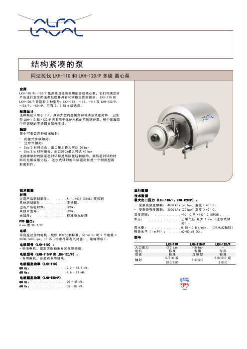
技术数据材料过流产品钢制部件:....W.1.4404(316L)双相钢其他钢制部件:.......不锈钢。
过流产品密封件:......EPDM。
其他O型环:........EPDM。
光洁度:..........标准喷丸处理FSS接口:6mm管/Rp1/8"电机带底座法兰的电机,按照IEC公制标准,50/60Hz时2个电极= 3000/3600rpm,IP55(排水孔带有汽封塞),绝缘等级F。
电机型号(LKH-110):-标准电机,固定滚珠轴承安装在驱动端。
电机型号(LKH-110/P和LKH-120/P):-专用电机,安装有专用轴承。
电机额定功率(LKH-110)50Hz:...........2.2-18.5kW。
60Hz:...........4.6-21kW。
电机额定功率(LKH-120/P)50Hz:...........30-45kW。
60Hz:...........35-87kW。
运行数据技术数据最大出口压力(LKH-110/P、LKH-120/P):-受泵壳强度限制:4000kPa(40bar)温度<40°C。
-受泵壳强度限制:2000kPa(20bar)温度>40°C。
温度范围:.........-10°C至+140°C(EPDM)。
水压:...........正常气压最大1bar(注水式轴封)。
用水量:..........0.25-0.5l/min。
(注水式轴封)噪音水平(1m时):....60-80dB(A)。
型号LKH-110LKH-110/P LKH-120/P入口压力<10bar>10bar-电机标准专用专用后板标准加强型标准轴封C/SIC或SIC/SICSIC/SICSIC/SIC或SIC/C尺寸(mm)流量图泵的具体措施泵的型号LKH-112LKH-113LKH-114LKH-122LKH-123LKH-124A 140140140265265265B 868686112112112C 76767685142200D 256256256335335335E108142184112168226泵的具体措施电机IEC IEC90IEC100IEC112IEC132IEC160IEC180IEC200IEC250电机kW 2.2 3.0 4.0 5.5/7.511/15/18.52230/37/4555/75F(max)*262282285304332352372446G 157185198196262286399410H 288325359383485533670753I 4345164975977918429801231*可能缩小尺寸F至最小。
阿法拉伐LKH-35安装调整

11.将螺帽O型圈(38)涂抹少量食品级 白油装入叶轮(27)槽内. 12.将叶轮螺帽(36)旋入泵轴,旋紧固定叶 轮不能有间隙,注意:叶轮螺帽螺纹M8
13.用橡胶锤击打叶轮中心螺帽(36)调整 间隙至0.5mm。
4.将动环O型圈涂抹少量食品级白油装入 动环内(14)。
5.将机械密封动组件(10,13,14,15)装入 泵轴上,注意:动环固定座槽口B对正泵 轴上定位销A(18).
6.旋转动环组件使动环固定座(10) 上定位销C对正动环(14)上凹槽口D。
7.将静环O型圈(12)涂抹少量食品级白 油装入背盘槽内。 8.将机械密封静环(11)用专用工具旋入 背盘内拧紧。
13.用橡胶锤击打叶轮中心调整 叶轮与背盘间隙至今0.5mm.
14.拧紧螺丝(6),保证泵轴完全固 定在泵轴上没有窜动.
15.将O型圈(24)涂抹少量食品级 白油后装入背盘(25)4, 手动转动叶轮观察有无磨 察现象。
17.通电试转观察有无异常声音, 注意观察泵旋转方向是否符合 要求。
UHT送料泵维护保养
LKH-35离心泵拆卸,安装与调整
LKH-35泵结构分解图
离心泵工作原理
• 离心泵的工作原理是:离心泵之所以能把水送出去是由于离心力的作用。水 泵在工作前,泵体和进水管必须罐满水形成真空状态,当叶轮快速转动时, 叶片促使水快速旋转,旋转着的水在离心力的作用下从叶轮中飞去,泵内的 水被抛出后,叶轮的中心部分形成真空区域。水源的水在大气压力(或水压 )的作用下通过管网压到了进水管内。这样循环不已,就可以实现连续抽水 。在此值得一提的是:离心泵启动前一定要向泵壳内充满水以后,方可启动 ,否则泵体将不能完成吸液,造成泵体发热,震动,不出水,产生“空转” ,对水泵造成损坏(简称“气缚”)造成设备事故。
Alpha液压系统安装说明201410

说明
Alpha 1液压系统是海沃针对自卸车的需求,经过充 分的市场调研,根据自卸车应用的特点,推出的新一代 前举液压系统。
为使大家了解Alpha 1的应用及安装要求,特此整理 以下安装说明文件以供参考。
Alpha系列与K系列对照
K系列 150 172 196
Alpha系列 137 157 157HD
油箱的安装
(4)注意油箱与托架的位置关系,油箱保持竖直状态,如右图 ;
(5)油箱扎带拧紧螺栓时,螺栓拧紧力矩30N.m,请分多次、 对称拧紧。避免单边拧紧螺栓时,会造成油箱偏斜;
(6)车辆行驶1000公里后检查油箱扎带是否有松动。
油箱的安装
(7)液压油的加注 Alpha油箱采用多夜位设计,加注液 压油 至透明液位计高度位置即可。
请勿与3K油缸油泵混淆,Alpha油缸压力为250bar,3K油缸为220bar. ➢ 泵支架折弯角度应和取力器倾角α相同,如下页的右上图
齿轮泵布置与安装
传动轴的安装要求
➢ 布置传动轴时,如果取力器输出轴与齿轮泵输入 轴保持平行,传动轴与水平夹角4-5°;如果输出 轴与输入轴呈W型时,输入轴和输出轴与传动轴线 的夹角要相等,且小于6°;右上图
其他方面
该技术参数表中主要包含信息:
1. 油缸外形; 2. 油缸安装尺寸; 3. 油缸技术参数; 4. 油缸举升能力表格;
油缸安装时注意事项:
1. 油缸的安装距必须控制在规定范围内, 否则将造成异常损坏;
2. 油缸最大前倾角小于10度; 3. 油缸举升时最大后转角小于29度; 4、上下支架安装螺栓等级建议10.9级; 5、油缸要与底盘车架、车厢在同一中心线; 6、上下支架与油缸耳轴的间隙小于2mm.
阿伐拉发卫生离心泵

频率: 50 Hz
LKH系列泵的性能: LKH泵有各种排量与压力型号可供选择,其排量最高为40立方米/小时,压力最高为190 m(19 bar/275 psi)。 6
LKH
LKH是一种高效经济的离心泵系列,既可满足卫生 且对产品进行柔和处理的要求,又具有化学稳定性, 其前端装载设计使得快速有效的维护成为可能,有 助 于延长其 工作 时 间,并且 实 现 较 低 的 拥 有成 本。LKH系列有13个尺寸可供选择,其高效驱动的特 点,有助于为选定流量优化性能,并且符合3-A,CE 和EHEDG认证要求。
重型变速箱配备 这些泵产品安装有采用 了重型圆锥滚子轴承和 扭矩锁定组件的铸铁变 速箱,因而使得产品易 于维护,且具有很高的 可靠性。
CIP与SIP 我们的容积泵产品非 常适合要求实现在线 清洗和在线消毒的应 用领域。
标准与 认证 我们所有的容积泵产品 都符合CE指令,EHEDG 认证,3-A认证以及FDA 卫生标准。此外,S X 和 SRU泵系列能够满足 ATEX对在易爆环境下使 用而提出的要求。
5 –10 15
20 25
35
40 45
S一in冲gl洗e fl式us轴he封d 单S一in轴gle封 双D面ou轴ble封
SolidC 1 SolidC 2 SolidC 3
50 60
SolidC 4
相同的轴封易于维护,且使用起来灵活方便。所有LKH标准型式(LKH 5–60) 以及SolidC系列 (SolidC 1–4)均采用相同尺寸的同款轴封,因 而只需放置相应的备件,库存得以简化且成本低廉。另外,单一机械式轴封可以在几分钟内就很容易地换成冲洗式或双面机械轴封,仅需增 加一些额外的部件。
我 公司的 容 积 泵 产 品包含 四 个系 列 :S X ,S R U , OptiLobe以及SCPP。
阿法拉伐离心机中文说明

目录1安全说明…………………………………………………………1.0-1 2卧螺离心机的操作原理………………………………………2.0-12.1 主电机………..…………………………………………….………………2.1-12.2后驱动系统……………..…………………………………………………2.2-12.2.1变频后驱动(VFD)..…….……………………………………………… 2.2-2 3操作和日常维护…………………………………………………3.1-13.1在第一次开车前……………..………………………………………………3.1-13.1.1噪声和振动…………...……...………………………………………….…3.1-23.2开车和停车程序…………………..…………………………………………3.2-13.2.1 检查转鼓……..…………………………………………………………….3.2-13.2.2开车前…………..………………………………………………………….3.2-13.2.2.1............................................................... 检查要点………….……………….……………………………………..3.2-13.2.2.2.................................................. 具有机械密封的离心机…………………..……………………………..3.2-13.2.3启动离心机………………………………………..……………………….3.2-23.2.4离心机停车……………………………………………..………………….3.2-23.3监控操作……………………………………………………………………..3.3-13.3.1过载………………………………………………………………………...3.3-13.3.1.1............................................................. 过载的原因………………………………………………………………3.3-13.3.1.2........................................................ 清理过载的转鼓…………………………………………………………3.3-23.3.2振动………………………………………………………………………...3.3-2 .....3.3.2.1振动开关(可选设备)…………………………………………………3.3-3 3.3.3监测螺旋磨损……………………………………………………………...3.3-73.4定期清洗过程………………………………………………………………..3.4-13.5优化操作……………………………………………………………………..3.5-13.6主电机………………………………………………………………………..3.6-13.7变频驱(VFD)……………………………………………………………...3.7-1 3.7.1调整转鼓速度传感器(图3.7.1)……………………………………….. 3.7-13.8润滑…………………………………………………………………………..3.8-13.8.1主轴承……………………………...………………………………………3.8-13.8.2螺旋轴承(图3.8.2中的加油嘴3和4)………………………………...3.8-13.8.3齿轮箱(图3.8.3)………………………………………………………...3.8-43.9维护表……………………………...…………………………………………3.9-13.9.1润滑时间和维护方法……………………………………………………...3.9-2表 3.9.1润滑表………………………………………………………….…3.9-2表 3.9.1.1维护周期…………………………………………………………3.9-33.9.2润滑剂型号………………………………………………………………...3.9-4 表3.9.2润滑剂、润滑工具表……………………………………………3.9-44拆卸和组装………………………………………………………4.0-04.1旋转组件……………………………………………………………………...4.1-14.1.1拆卸转鼓(图4.1.1和4.1.2)…………………………………………….4.1-14.1.2安装转鼓(图4.1.1和4.1.2)…………………………………………….4.1-54.1.3拆卸大端轴颈(图4.1.4)………………………………………………...4.1-74.1.4安装大端轴颈(图4.1.4)………………………………………………...4.1-74.1.5拆卸小端轴颈(图4.1.5)………………………………………………...4.1-94.1.6安装小端轴颈(图4.1.5)……………………………………………….4.1-104.1.7拆卸齿轮箱(图4.1.6和4.1.8)………………………………………….4.1-114.1.8安装齿轮箱(图4.1.7和4.1.8)…………………………………………4.1-134.1.9装配新的排污口衬套…………………….………………………………4.1-144.2主轴承…………….…………………………………………………………..4.2-1 4.2.1拆卸大端主轴承(图4.2.1)…………………………………….…………..4.2-14.2.2组装大端主轴承(图4.2.1)………………………………………………...4.2-34.2.3拆卸小端主轴承(图4.2.4)………………………………………………...4.2-74.2.4安装小端主轴承(图4.2.4)………………………………………………...4.2-94.3螺旋轴承……………………………………………………….…….……….4.3-14.3.1拆卸螺旋大端轴承(图4.3.1)…………………………………….………..4.3-14.3.2组装螺旋轴承大端轴承(图4.3.1)………………………………………4.3-34.3.3拆卸螺旋轴承小端轴承(图4.3.4)……………………………………...4.3-74.3.4安装螺旋轴承小端轴承(图4.3.4)……………………………………...4.3-84.4螺旋…………………………………………………………………………...4.4-1 4.4.1从转鼓中拆卸螺旋(图4.4.1)……………………………………………4.4-14.4.2将螺旋装入转鼓(图4.4.1)………………………………………………...4.4-24.5主电机……………………………………………………………………….. 4.5-14.5.1拆卸主电机(图4.5.1)……………………………………………….…..4.5-14.5.2组装主电机(图4.5.1,4.5.2和4.5.3)………………………………….…..4.5-54.5.3调紧V形皮带,皮带力表………………………………………………4.5-74.6变频后驱动装置(VFD)…………………….……………………………..4.6-1 4.6.1拆卸变频驱动器(图4.6.1)………….………………………………….4.6-14.6.2组装变频驱动器(图4.6.1)……………………………………………..4.6-15补充文档…………………………………………………………5.0-01安全说明请务必严格按照以下要求进行操作,否则会给您造成人员以及财产的损失。
853控制柜调试指导书
为099-100。
6.6.5. 再将载重量增加至额定载荷就可达到超载报警。
称重装置的插头端子对照表见下面表格。
6.7、舒适感调整一般情况下调整3319中的加速度、减速度及其jerk0-jerk3进行调整。
根据现场的实际情况而定,一般不调。
6.8、试外招和消防a用万用表量H4插键是否有短路,正常后插好,拨好地址码。
外召地址从21开始,一个地址一层,以此类推,按下按钮能呼到指定楼层,完毕。
b按下消防开关,电梯能返回指定楼层,且轿厢显示紧急退出,轿门一直打开,则正常。
以上结束后电梯上下反复运行几次,正常则调试完毕。
七、故障排除3.9编码器定位出厂时主机已经与控制柜进行配对试验,定位角度已经存在变频器中,如果发现主机运行异常或驱动器内参数与主机实际参数不符,则需要重新定位。
断电,将钢丝绳拨离曳引轮,短接SW-A1和BY-A1到AC110V,上电使接触器吸合,设置好驱动器参数和电机铭牌参数,将RUN SOURCE设成“0”,RUN ENABLE设成“0”。
用服务器插入SVT2,并按“M-3-3-2”并按“ENTER”键进行确认主机定位,注意:定位过程中主机将旋转(在此过程中要确认抱闸已经打开);等待服务器出现“Learning finished”表示定位完成;注意:如果电机相位更换,则需要进行重新定位,或更改成原来相位;3.10点动运行时,BY、SW不能正常吸合检查安全信号输入、输出(IO)信号是否正常,如不正常应根据原理图检查线路;如信号正常,请检查驱动器参数,参见驱动器参数表。
3.11点动运行时,接触器、抱闸继电器及抱闸正常打开,电机不转,电流很大“Drive Overload”。
可能是变频器到主机三相相序不对,应按照正确方法连接主机动力线,参见“2.6 动力线检查”。
3.12自学习运行到顶层后,电梯不能正常运行检查run enable值,应该设置成“1”,另外请检查井道信号是否正常。
3.13常见驱动器故障3.13.1驱动器“Over current”信息电流过大。
阿尔法拉瓦尔Unique RV-P调节阀门说明说明书

actuator is fitted to the valve body by means of a clamp. The Kv value is flexible as lower element can be exchanged.Manual and aseptic versions are available. Upon request, the valve can also be supplied with a normally closed (NC)actuator.Working principleThe Alfa Laval Unique RV-P Regulating Valve is controlled from a remote location by means of compressed air. An actuator with an integrated IP converter IP convertertransforms the electrical signal to a pneumatic signal. This signal conversion is based on a highly accurate and reliable contactless AMR sensor, making it insensitive to vibrations and pressure shocks. The pneumatic signal is transmitted to the integrated positioner which operates by means of the force-balance principle, ensuring that the position of the actuator piston is directly proportional to the input signal.Signal range and zero point can be adjusted individually. The actuator can be used for split-range operation by using a different measuring spring.CertificatesTECHNICAL DATAMin. product pressure:Full vacuumTemperature range:-10 °C to 140 °C (EPDM)Flow range Kv (Δ P = 1bar):0.5 to 110 m3/hMax. pressure drop:500 kPa (5 bar)Max. pressure:600 kPa (6 bar)Working pressure:400 kPa (4 bar)Max. size of particles:0.01 mmMax. oil content:0.08 ppmDew point:10 °C below ambient temp. or lowerMax. water content:7.5 g/kgInput resistance:200 ΩInductivity/capacitance:NegligiblePHYSICAL DATAOther steel parts: 1.4301(304)Product wetted seals:EPDMExternal finish:Semi-bright (blasted)Internal finish:Bright (polished) RA<0.8 µmDiaphragms:NBR with reinforced fabric insertSprings:Stainless steel uncovered/spring steel epoxy resin coatedActuator stem:PolyamideScrews, nuts:Stainless steel, polyamideOther parts:Stainless steelValve body combinations64-542200300AccuracyDeviation:≤1.5%Hysteresis:≤0.5%Sensitivity:<0.1%Influence of air supply pressure:≤0.1% between 1.4 and 6 barAir consumption at steady state condition:With 0.6 bar signal pressure and supply pressures up to 6 bar ≤100 In/h Ambient temperature:-25 °C to +70 °CProtection class:IP 66Flow sizes/tube connections1.0 E1038403277-52 E1238403277-5 4 E1438403277-5 8 E2338403277-5 16 E2938403277-5 25 E3851503277-5 32 E48.551503277-5 40 E4263.5653277-5 64 L5163.5653277-5 75 L5176.1803277-5110 L72101.61003277-5Options•Male parts or clamp liners in accordance with required standard•Product wetted seals of HNBR or Fluorinated rubber (FPM)•Profibus communication•Aseptic configuration Max 8 barA- aseptic411426412446470488414427418454472490 E566367859696576470899898 G49.561818611911949.5627887120120 H168168168168168280168168168168168280 OD385163.576.1101.6101.641537085104104 ID34.847.860.372.997.697.638506681100100 t 1.6 1.6 1.6 1.622 1.5 1.52222M/ISO clamp212121212121------M/DIN clamp------212128282828 M/DIN male------222325253030 M/SMS male202024243535------Weight kg8.29.39.711.215.424.98.29.39.711.215.424.9Capacity diagram For Δ P= 100 kPa (1bar).Figure 1. StandardFigure 2. Aseptic*Recommended working areaNote! For the diagram the following applies:Medium: Water (20 °C).Measurement: In accordance with VDI 2173.Alfa Laval recommend max. flow velocity in tubing and valves to be 5 m/sec.Conversion Table 100 kPa = 1 bar = 14.5 PSI 10 mm = 0.39 inch 10 m 3/h = 44.03 US GPM Pressure drop calculationThe Kv designation is the flow rate in m 3/h at a pressure drop of 1 bar when the valve is fully open (water at 20°C or similar liquids). To select the Kv value it is necessary to calculate the Kv q value using the following formula:Where:Kv q = Kv value at specific flow and specific pressure drop Q = Flow rate (m 3/h)Δ P = Pressure drop over valve (bar)Electrical connectionElectrical connection - Analogue 4-20 mA Positioner 37252405-0035Cable gland Cover240500362405-0037Terminal screws4-20 mA control signalRoute the two-wire line to the screw terminals marked “11 and 12”, whereby the correct polarity has to be ensured 1.Open the cover of the positioner for electrical connection2.Fit the cable through the cable gland and connect the cable wires to the terminal screws. (+11 and -12)3.Tighten the cable gland and close the cover of the positioner Electrical connection - Profibus PA Positioner 3730-42405-0035Cable gland Cover2405-00382405-0039Terminal screwsBus control signalRoute the two-wire bus line to the screw terminals marked “IEC 1158-2”, whereby no polarity has to be observed 1.Open the cover of the positioner for electrical connection2.Fit the bus cable through the cable gland and connect the cable wires to the terminal screws. (IEC 1158-2)3.Tighten the cable gland and close the cover of the positionerBy searching on positioner type 3730-4 you can either retrieve the GSD files for PROFIBUS PA communication directly from the World Wide Web server of Samson or the PROFIBUS User OrganizationThis document and its contents are subject to copyrights and other intellectual property rights owned by Alfa Laval Corporate AB. No part of this document may be copied, re-produced or transmitted in any form or by any means, or for any purpose, without Alfa Laval Corporate AB’s prior express written permission. Information and services provided in this document are made as a benefit and service to the user, and no representations or warranties are made about the accuracy or suitability of this information and these services for any purpose. All rights are reserved.200003961-1-EN-GB© Alfa Laval Corporate AB How to contact Alfa LavalUp-to-date Alfa Laval contact details for all countries are always availableon our website at 。
阿尔法拉瓦中心力泵LKH-35零件清单说明书

Spare Parts ListAlfa LavalPage 2 of 40300 Version 1Parts for double mechanical shaft seal Parts for flushed shaft sealCentrifugal PumpLKH-35Page 3 of 40300Version 13-5 Hp 7.5-10 Hp 15-20 Hp 25-30 Hp Pos.Qty.DescriptionPart No.Part No.Part No.Part No.11Motor5a 1Compression ring with thread.................5b 1Compression ring without thread............66Screw.......................................................6a 6Washer ....................................................71Stub shaft ................................................81Connex pin . (10)1Drive ring - single shaft seal ...................1Drive ring - flush shaft seal.....................11àØ♦q m ²1Stationary seal ring, SC ..........................12àØ♦q m ²1Stationary O-ring, EPDM (standard)......1Stationary O-ring, FPM ...........................1Stationary O-ring, NBR ...........................1Stationary O-ring, PTFE .........................13àØ♦q m ²1Spring.......................................................161Adaptor ....................................................174Adaptor screw.........................................194Adaptor spring washer............................202Adaptor nut ..............................................212Washer ....................................................221Safety guard............................................231Safety guard screw.................................246Wingnuts..................................................24a 6Spring washer .. (25)1Back plate polished .................................26q m ²1Joint ring, EPDM (standard)...................1Joint ring, FPM ........................................1Joint ring, NBR ........................................1Joint ring, PTFE.......................................286Stud bolt (29)1Pump casing............................................30a-351Leg assembly ..........................................361Impeller screw .. (37)1Impeller polished, full ...............................38q m ²1Impeller O-ring, EPDM (standard)..........1Impeller O-ring, FPM...............................1Impeller O-ring, NBR...............................1Impeller O-ring, PTFE .............................40a 1Seal housing - double mechanical..........40b 1Seal housing - flushed.............................412Screw for seal housing ...........................422Water flush pipe.......................................43Øm1Lip seal.....................................................44Ø♦m ²1Seal housing O-ring ................................45Øm 1Drive ring O-ring......................................50♦²1O-ring.......................................................51♦²1Sec. stationary seal ring, SC ..................52♦²1Spacer .....................................................Parts marked with à,Ø,♦ are included in the seal kits.Parts marked with à,Ø,♦,q ,m ,² are included in the service kits.9612-13-36029612-13-37029611-99-31969611-99-31999612-13-31029611-99-06229612-13-77019612-13-97019612-13-79019611-99-21499611-99-21509611-99-21519611-99-21529612-13-76019612-13-5911881-30173881-298359611-99-03539611-99-25599612-13-110631460-1309-19611-41-68929611-99-18889612-13-84269611-99-29839611-99-29859611-99-29849611-99-29869611-99-2169883-412169612-13-59209612-13-96039612-43-41069611-99-21459611-99-21469611-99-21479611-99-21489612-13-39029612-13-39019611-99-020331457-0056-131446-0088-29611-99-21539611-99-21459611-99-21569612-13-83029612-30-89019612-13-36069612-13-37069611-99-23389611-99-31999612-13-32029611-99-06229612-13-77019612-13-97019612-13-79019611-99-21499611-99-21509611-99-21519611-99-21529612-13-76019612-13-5912881-30173881-298359611-99-03539611-99-25599612-13-110731460-1309-19611-41-68929611-99-18889612-13-84269611-99-29839611-99-29859611-99-29849611-99-29869611-99-2169883-4121631460-1301-49612-13-96039612-43-41069611-99-21459611-99-21469611-99-21479611-99-21489612-13-39029612-13-39019611-99-020331457-0056-131446-0088-29611-99-21539611-99-21459611-99-21569612-13-83029612-30-89019612-13-36039612-13-37039611-99-23389611-99-31999612-13-33029611-99-06229612-13-77019612-13-97019612-13-79019611-99-21499611-99-21509611-99-21519611-99-21529612-13-76019612-13-5913881-30173881-298359611-99-03539611-99-25599612-13-110831460-1309-19611-41-68929611-99-18889612-13-84269611-99-29839611-99-29859611-99-29849611-99-29869611-99-2169883-4121631460-1302-39612-13-96039612-43-41069611-99-21459611-99-21469611-99-21479611-99-21489612-13-39029612-13-39019611-99-020331457-0056-131446-0088-29611-99-21539611-99-21459611-99-21569612-13-83029612-30-89019612-13-36039612-13-37039611-99-25049611-99-31999612-13-33029611-99-06229612-13-77019612-13-97019612-13-79019611-99-21499611-99-21509611-99-21519611-99-21529612-13-76019612-135918881-30173881-298359611-99-03539611-99-25599612-13-110831460-1309-19611-41-68929611-99-18889612-13-84269611-99-29839611-99-29859611-99-29849611-99-29869611-99-2169883-4121631460-1302-49612-13-96039612-43-41069611-99-21459611-99-21469611-99-21479611-99-21489612-13-39029612-13-39019611-99-020331457-0056-131446-0088-29611-99-21539611-99-21459611-99-21569612-13-83029612-30-890114àØq m 1Rotating seal ring, Carbon ......................9612-13-64019612-13-64019612-13-64019612-13-64011Rotating seal ring, SC .............................9612-13-64029612-13-64029612-13-64029612-13-6402♦²2Rotating seal ring, Carbon ......................9612-13-64019612-13-64019612-13-64019612-13-64012Rotating seal ring, SC .............................9612-13-64029612-13-64029612-13-64029612-13-640215àØq m1Rotating O-ring, EPDM (standard).........9611-99-21459611-99-21459611-99-21459611-99-21451Rotating O-ring, FPM ..............................9611-99-21469611-99-21469611-99-21469611-99-21461Rotating O-ring, NBR ..............................9611-99-21479611-99-21479611-99-21479611-99-21471Rotating O-ring, PTFE ............................9611-99-21489611-99-21489611-99-21489611-99-2148♦²2Rotating O-ring, EPDM (standard).........9611-99-21459611-99-21459611-99-21459611-99-21452Rotating O-ring, FPM ..............................9611-99-21469611-99-21469611-99-21469611-99-21462Rotating O-ring, NBR ..............................9611-99-21479611-99-21479611-99-21479611-99-21472Rotating O-ring, PTFE ............................9611-99-21489611-99-21489611-99-21489611-99-2148Alfa LavalCentrifugal PumpLKH-35Page 4 of 40300Version 11-40 Hp Pos.Qty.DescriptionPart No.Seal Kit for Single Shaft Seal à1C/SC seal kit, EPDM .........................................................................................9612-1296-09à1C/SC seal kit, NBR............................................................................................9612-1296-10à1C/SC seal kit, FPM ............................................................................................9612-1296-11à1SC/SC seal kit, EPDM .......................................................................................9612-1296-05à1SC/SC seal kit, NBR .........................................................................................9612-1296-06à1SC/SC seal kit, FPM..........................................................................................9612-1296-07Seal Kit for Flushed Shaft Seal Ø1C/SC seal kit, EPDM .........................................................................................9612-1296-09Ø1C/SC seal kit, NBR............................................................................................9612-1296-10Ø1C/SC seal kit, FPM ............................................................................................9612-1296-11Ø1SC/SC seal kit, EPDM .......................................................................................9612-1296-05Ø1SC/SC seal kit, NBR .........................................................................................9612-1296-06Ø1SC/SC seal kit, FPM..........................................................................................9612-1296-07Seal Kit for Double Mechanical Shaft Seal ♦1C/SC seal kit, EPDM .........................................................................................9612-1296-13♦1C/SC seal kit, NBR............................................................................................9612-1296-14♦1C/SC seal kit, FPM ............................................................................................9612-1296-15♦1SC/SC seal kit, EPDM .......................................................................................9612-1296-17♦1SC/SC seal kit, NBR .........................................................................................9612-1296-18♦1SC/SC seal kit, FPM..........................................................................................9612-1296-19Parts marked with à,Ø,♦ are included in the seal kits.Service Kit for Single Shaft Seal q 1Service kit, EPDM .............................................................................................9611-92-2182q 1Service kit, NBR................................................................................................9611-92-2183q 1Service kit, FPM ................................................................................................9611-92-2184q 1Service kit, PTFE ..............................................................................................9611-92-2185Service Kit for Flushed Shaft Seal m 1Service kit, EPDM .............................................................................................9611-92-2190m 1Service kit, NBR................................................................................................9611-92-2191m 1Service kit, FPM ................................................................................................9611-92-2192m 1Service kit, PTFE ..............................................................................................9611-92-2193Service Kit for Double Mechanical Shaft Seal ²1Service kit, EPDM .............................................................................................9911-92-2226²1Service kit, NBR................................................................................................9611-92-2227²1Service kit, FPM ................................................................................................9611-92-2228²1Sevice kit, PTFE................................................................................................9611-92-2229Parts marked with à,Ø,♦,q ,m ,² are included in the service kits.Conversion Kits1Single to flushed shaft seal.........................................................................9611-92-2042(The conversion kit contains Pos. 10, 40, 41, 42, 43, 44, 45)1Single to double mechanical shaft seal ...................................................9611-92-2175(The conversion kit contains Pos. 14, 15, 40a, 41, 42, 44, 50, 51, 52)1Flushed to double mechanical shaft seal................................................9611-92-2176(The conversion kit contains Pos. 14, 40a, 50, 51, 52)Accessories1Tool complete .................................................................................................9612-1371-018201 104th StreetPleasant Prairie, WI 53158-0909Telephone: 800-558-2060Fax: 262-947-4724。
阿法拉伐卫生离心泵安全操作及保养规程

阿法拉伐卫生离心泵安全操作及保养规程阿法拉伐卫生离心泵是一种高效、卫生、节能的离心泵,广泛应用于食品、制药、生物工程、化工等领域。
为了确保设备的正常运行,防止事故发生,特制定本安全操作及保养规程。
一、设备安装1.在安装前,必须对设备进行质量检查,确保设备完好无损,各部件齐全。
2.设备应安装在水平平整的基础上,基础的强度应满足设备运行时的振动要求。
3.安装完成后,应对设备各部位进行细致的检查,确保连接紧密、无漏水、无异响等情况。
二、设备调试1.对设备进行调试前,应先检查各部位的齿轮、轴承、联轴器等件是否加注充分润滑油,并进行磨合。
2.在调试前,必须检查各电器线路是否正确接线,各安全保护装置是否正常。
3.在调试中,应按照阀门开启、关闭的顺序进行,同时观测系统压力、温度是否正常,并检查管道是否有漏。
三、设备操作1.操作前应检查设备是否处于正常状态,各安全保护装置是否正常。
2.启动设备前,应按照启动步骤进行,同时注意观察液位、压力、温度等情况。
3.设备运行中应及时检查液位、温度、振动、噪声等情况,如出现异常应及时处理。
4.设备停止运行后,应按照停车步骤进行,并对设备进行清洗。
四、设备保养1.对设备进行日常保养时,应先断电、气源,将设备清洗干净,用干净的软布擦拭设备表面,定期清除积尘。
2.检查设备通风孔是否畅通,电气控制箱内部是否干燥,各电气接头是否松动。
3.定期对设备进行检查、清洗、养护,更换易损件。
4.每年对设备进行大修,更换润滑油和密封件等。
五、设备安全1.在设备运行时,应根据设备状态调整阀门和泵的流量,避免超过设备额定流量。
2.在设备完全停止后,应关闭电源及气源,确保设备处于安全状态。
3.设备维护或检修时,应贴上明显的“禁止启动”标志,防止误操作。
4.设备周围环境一定要保持清洁整洁,避免杂物堆积或者易燃物品存在。
六、设备故障和维修1.发现设备故障时,应立即停机,并进行故障排除。
2.在进行设备维修时,应戴上防护用品,避免接触物体或工具进入泵体内部,以免造成意外损伤。
- 1、下载文档前请自行甄别文档内容的完整性,平台不提供额外的编辑、内容补充、找答案等附加服务。
- 2、"仅部分预览"的文档,不可在线预览部分如存在完整性等问题,可反馈申请退款(可完整预览的文档不适用该条件!)。
- 3、如文档侵犯您的权益,请联系客服反馈,我们会尽快为您处理(人工客服工作时间:9:00-18:30)。
10.将叶轮(27)装入泵轴上,拧紧 不能有间隙。
11.将叶轮螺帽O型圈(38)涂抹少量 食品级白油装入叶轮(27)槽内。
12.将叶轮螺帽(36)旋入泵轴, 拧紧固定叶轮不能有间隙。
注意:叶轮螺帽螺纹M8.
13.用橡胶锤击打叶轮中心调整 叶轮与背盘间隙至今0.5mm.
14.拧紧螺丝(6),保证泵轴完全固 定在泵轴上没有窜动.
2.将组装好的泵轴沿轴线方向套入电机 轴上,泵轴与电机距离10-20mm,拧 紧螺丝但不要太紧以便后续调整间隙。
3.将延伸套架(16)装入电机上拧紧 螺丝(17)。
4.将动环O型圈涂抹少量食品级白油装入 动环内(14)。
5.将机械密封动组件(10,13,14,15)装入 泵轴上,注意:动环固定座槽口B对正泵 轴上定位销A(18).
12.将叶轮螺帽(36)旋入泵轴,旋紧固定叶 轮不能有间隙,注意:叶轮螺帽螺纹M8
13.用橡胶锤击打叶轮中心螺帽(36)调整 间隙至0.5mm。
15.将O型圈(24)涂抹少量食品级 白油后装入背盘(25)槽内。
16.装入泵壳29,拧紧螺丝 28, 套上垫片24a,旋紧螺母24, 手动转动叶轮观察有无磨
察现象。
17.通电试转观察有无异常声音, 注意观察泵旋转方向是否符合 要求。
11.将螺帽O型圈(38)涂抹少量食品级 白油装入叶轮(27)槽内.
6.旋转动环组件使动环固定座(10) 上定位销C对正动环(14)上凹槽口D。
Hale Waihona Puke 7.将静环O型圈(12)涂抹少量食品级白 油装入背盘槽内。
8.将机械密封静环(11)用专用工具旋入 背盘内拧紧。
9.将背盘装入延伸套架上,套上平垫 ,弹垫(21),拧紧螺母(20)。
注意:机械密封动组件销钉和槽口是
否对正。
UHT送料泵维护保养
LKH-35离心泵拆卸,安装与调整
LKH-35泵结构分解图
离心泵工作原理
• 离心泵的工作原理是:离心泵之所以能把水送出去是由于离心力的作用。水 泵在工作前,泵体和进水管必须罐满水形成真空状态,当叶轮快速转动时, 叶片促使水快速旋转,旋转着的水在离心力的作用下从叶轮中飞去,泵内的 水被抛出后,叶轮的中心部分形成真空区域。水源的水在大气压力(或水压 )的作用下通过管网压到了进水管内。这样循环不已,就可以实现连续抽水 。在此值得一提的是:离心泵启动前一定要向泵壳内充满水以后,方可启动 ,否则泵体将不能完成吸液,造成泵体发热,震动,不出水,产生“空转” ,对水泵造成损坏(简称“气缚”)造成设备事故。
LKH-35泵拆卸
拆卸泵轴 1.松开法兰螺丝(6,6a). 2.沿轴线方向拉出泵轴组件.
拆卸叶轮 1.拆开叶轮固定螺帽(36,螺纹M8)。 2.用螺丝刀固定泵轴旋转,再用橡胶锤
沿叶旋转方向击打叶轮至松开螺纹。 3.旋出叶轮(27 叶轮螺纹M20)。
用螺丝刀固定泵轴旋转
LKH-35泵安装步骤
1.将固定法兰(5a,5b)按锥度方向套入 泵轴(7)上,拧上螺丝(6,6a)。
