SP522中文资料
普鲁兰酶的研究进展
普鲁兰酶的研究进展董桂秀;杨平平;夏涛;邱永乾;毛相朝【摘要】普鲁兰酶,是能够专一性切开支链淀粉中分支点处α-1,6-糖苷键的一种脱支酶,它在以淀粉为原料的食品工业中有着重要的应用.通过对该领域研究成果的整理,对产普鲁兰酶的微生物选育、酶的分离纯化、酶学性质特点、酶的应用等方面进行了综述.%Pullulanase ia a type of debranching enzyme which can specifically attack a-1,6 linkages in amylopectin, and it has important applications in (pod processing industry. In this paper, the research findings about pullulananse were summarized, and the breeding of pullula-nase-producing microorganism, as well as the separation, purification, characteristics and application of the pullulanase were reviewed.【期刊名称】《安徽农业科学》【年(卷),期】2012(000)018【总页数】5页(P9874-9877,9958)【关键词】普鲁兰酶;菌种选育;纯化;应用;研究进展【作者】董桂秀;杨平平;夏涛;邱永乾;毛相朝【作者单位】山东轻工业学院食品与生物工程学院,山东济南250353;中国海洋大学食品科学与工程学院,山东青岛266003;山东轻工业学院食品与生物工程学院,山东济南250353;中国海洋大学食品科学与工程学院,山东青岛266003;中国海洋大学食品科学与工程学院,山东青岛266003;中国海洋大学食品科学与工程学院,山东青岛266003【正文语种】中文【中图分类】S188普鲁兰酶属于а-淀粉酶第13家族,是能够专一性切开支链淀粉中分支点处а-1,6-糖苷键的一种脱支酶。
MFRC522中文

非非接接触触式式读读卡卡器器 IICCLeabharlann 广州周立功单片机发展有限公司
目录
目录
1.简介 ................................................................................................................................................... 1 1.1 范围............................................................................................................................................1 1.2 概述............................................................................................................................................1 1.3 特性............................................................................................................................................1 1.4 简化MFRC522 框图..................................................................................................................2
IC资料-SMC522光电鼠标芯片

SMC522PS/2光电3D鼠标控制芯片SMC5221.概述SMC522是一款性能优良的PS/2光电3D鼠标控制芯片,可与PAN101B204/208系列、ADNS-2051系列配对使用构成高性能光电鼠标。
SMC522采用MICRO控制接口,可使鼠标的解析度400CPI/800CPI动态切换并适用于PS/2 2D 3KEY、PS/2 3D 3KEY、PS/2 3D 5KEY等多种工作模式(根据不同的系统及驱动程序自动切换)。
当工作于3D 3KEY模式时,其第4(Forward)、5(Back)两键相当于中间键。
2.主要特点● 与IBM PS/2 Mouse及Microsoft IntelliMouse完全兼容● 包括IBM PS/2 Mouse规格内的所有指令、回应、状态、错误处理等,毫无删减● PS/2 Mouse的同步串列传输时序精准,与各厂牌IBM PC相容型电脑的相容性最高● 采用MICRO控制接口,可使鼠标的解析度400CPI/800CPI动态切换● 兼容多种光电传感器● 兼容PS/2 2D 3KEY、PS/2 3D 3KEY、PS/2 3D 5KEY等多种工作模式● 仅须外接一个电阻组成RC振荡器,振荡频率8MHz● 外部的零件已减到最少,有效降低生产装配成本● 滚轮为除2设计,适合一般的编码器设计,同时也支持光学滚轮3.管脚排列4.管脚功能说明编号 引脚名 方向 功能描述1 Z1 I 侦测滚轮翻动的光耦或编码器输入2 PS_CLK I/O 与电脑做同步串行传输的CLK讯号线3 PS_DATA I/O 与电脑做同步串行传输的DATA讯号线4 GND - 地5 R I 鼠标右键的输入6 M I 鼠标中间键的输入7 L I 鼠标左键的输入8 FORWARD I 鼠标第4个键(Forward)的输入 9 BACK I 鼠标第5个键(Back)的输入10 PD/ICSel I Power_down 同步/IC 选择(上电时,悬空为选择PAN101B204/208,接下拉电阻选择ADNS-2051)11 SCLK/RESModeI/O 与PAN101B204/208、ADNS-2051通信的时钟线/解析度选择(工作中,悬空为800CPI,接下拉电阻为400CPI) 12 SDIO I/O 与PAN101B204/208、ADNS-2051通信的数据线 13 VDD -5V 电源 14 OSCOUT O 振荡输出 15 OSCIN I 振荡输入16 Z2I侦测滚轮翻动的光耦或编码器输入5.功能详述功能详述5.1 5.1 配置配置配置本产品主要采用Micro 控制方式,可以达到800CPI 的高性能。
深深圳圳市市矽矽普普特特科科技技有有限限公公司司 XXPPTT88000022 用户手册说明书
深圳市矽普特科技有限公司X P T8002单通道、2.4W、A B类音频功放X P T8002用户手册2011年10月深圳市矽普特科技有限公司X P T8002单通道、2.4W、A B类音频功放芯片功能说明XPT8002是一款桥式音频功率放大器。
5V 工作电压时,最大驱动功率为2.4W,音频范围内总谐波失真噪声小于1%(20Hz~20KHz);XPT8002的应用电路简单,只需极少数外围器件;XPT8002输出不需要外接耦合电容或上举电容和缓冲网络。
XPT8002采用SOP、ESOP封装,特别适合用于小音量、小体重的便携系统。
XPT8002可以通过控制进入休眠模式,从而减少功耗;XPT8002内部具有过热自动关断保护机制XPT8002工作稳定,增益带宽积高达2.5MHz,并且单位增益稳定。
通过配置外围电阻可以调整放大器的电压增益,方便应用。
芯片主要功能特性输出功率高(THD+N<10%,1KHz频率) 功率为2.4W(4Ω负载)掉电模式漏电流小:0.6uA(典型)采用SOP、ESOP封装外部增益可调宽工作电压范围2.0V—5.5V不需驱动输出耦合电容、自举电容和缓冲网络单位增益稳定实物图芯片应用场合手提电脑台式电脑低压音响系统芯片基本结构描述XPT8002是双端输出的音频功率放大器,在5V电压工作时,最大可以驱动输出功率为2.4W,音频范围内总谐波失真噪声小于1%(20Hz~20KHz)。
其原理框图为:芯片原理框图图1XPT8002原理框图芯片定购信息芯片型号封装类型包装类型最小包装数(PCS)备注XPT8002SO SOP8 管装100芯片的封装和引脚封装引脚图XPT8002的封装管脚图XPT8002管脚描述XPT8002管脚描述(SOP封装)管脚号符号描述1 SD 掉电控制管脚,高电平有效,2 BYP 内部共模电压旁路电容3 +IN 模拟输入端,正相4 -IN 模拟输入端,反相5 VO1 模拟输出端16 VDD 电源正7 GND 电源地8 VO2 模拟输出端2芯片特性说明芯片最大极限值芯片最大物理极限值参数最小值最大值单位说明电源电压 2.4 6 V 5.0储存温度-65 150 o C 25输入电压-0.3 VDD V内部限制功耗mW耐ESD电压1 3000 V HBM耐ESD电压2 250 V MM节温150 o C 典型值150推荐工作温度-40 85 o C 25推荐工作电压 2.0 5.5 5.0热阻焊接温度 220 o C 15秒内芯片数字逻辑特性关断信号数字逻辑特性参数最小值典型值最大值单位说明参数 最小值 典型值 最大值单位 说明 电源电压为5VVIH 1.5 V VIL 1.3 V 电源电压为3VVIH 1.3 V VIL 1.0 V 电源电压为2.6VVIH 1.2 V VIL 1.0 V电气特性除特别说明外,环境温度T A =25℃。
MHW5222A资料

Q
2 PL
0.25 (0.010)
M
T 1. DIMENSIONING AND TOLERANCING PER ANSI Y14.5M, 1982. 2. CONTROLLING DIMENSION: INCH. DIM A B C D E F G J K L N P Q R S U V W INCHES MIN MAX ––– 1.775 ––– 1.085 ––– 0.840 0.018 0.022 0.465 0.510 0.300 0.325 0.100 BSC 0.156 BSC 0.315 0.355 1.00 BSC 0.165 BSC 0.100 BSC 0.148 0.168 ––– 0.595 1.500 BSC 0.200 BSC 0.280 BSC 0.435 0.450 MILLIMETERS MIN MAX ––– 45.08 ––– 27.56 ––– 21.34 0.46 0.56 11.81 12.95 7.62 8.25 2.54 BSC 3.96 BSC 8.00 8.50 25.40 BSC 4.10 BSC 2.54 BSC 3.76 4.27 ––– 15.11 38.10 BSC 5.08 BSC 7.11 BSC 11.05 11.43
RF DEVICE DATA ©MOTOROLA Motorola, Inc. 1994
MHW5222A 1
元器件交易网
*DIN (European Applications Only)
NCTA Channel Designation P Q V W (Ref.) M8 M9 M14 (Ref.) M15 M20 M21 (Ref.) M22 M23 Frequency (MHz) 253.25 259.25 289.25 295.25 361.25 367.25 397.25 403.25 433.25 439.25 445.25 451.25 DIN Output Level (dBmV)**(Typ) + 59.5 + 59.5 + 65.5 + 65.5 + 59 + 59 + 65 + 65 + 64 + 64 + 58 + 58 DIN Beat Level dB Relative to Ref. Ch.
pt2262_pt2272中文资料

PT2262/PT2272编码解码芯片中文资料PT2262/PT2272是台湾普城公司生产的一种CMOS工艺制造的低功耗低价位通用编解码电路,PT2262/PT2272最多可有12位(A0-A11)三态地址端管脚(悬空,接高电平,接低电平),任意组合可提供531441地址码,PT2262最多可有6位(D0-D5)数据端管脚,设定的地址码和数据码从17脚串行输出,可用于无线遥控发射电路。
编码芯片PT2262发出的编码信号由:地址码、数据码、同步码组成一个完整的码字,解码芯片PT2272接收到信号后,其地址码经过两次比较核对后,VT脚才输出高电平,与此同时相应的数据脚也输出高电平,如果发送端一直按住按键,编码芯片也会连续发射。
当发射机没有按键按下时,PT2262不接通电源,其17脚为低电平,所以315MHz的高频发射电路不工作,当有按键按下时,PT2262得电工作,其第17脚输出经调制的串行数据信号,当17脚为高电平期间315MHz的高频发射电路起振并发射等幅高频信号,当17脚为低平期间3 15MHz的高频发射电路停止振荡,所以高频发射电路完全收控于PT2262的17脚输出的数字信号,从而对高频电路完成幅度键控(ASK调制)相当于调制度为100%的调幅。
PT2262/PT2272特点l CMOS工艺制造,低功耗l 外部元器件少l RC振荡电阻l 工作电压范围宽:2.6-15vl 数据最多可达6位l 地址码最多可达531441种PT2262/PT2272应用范围l 车辆防盗系统l 家庭防盗系统l 遥控玩具l 其他电器遥控PT2262 引脚图:PT2262管脚说明:名称管脚说明A0-A11 1-8、10-13 地址管脚,用于进行地址编码,可置为“0”,“1”,“f”(悬空),D0-D5 7-8、10-13 数据输入端,有一个为“1”即有编码发出,内部下拉Vcc 18 电源正端(+)Vss 9 电源负端(-)TE 14 编码启动端,用于多数据的编码发射,低电平有效;OSC1 16 振荡电阻输入端,与OSC2所接电阻决定振荡频率;OSC2 15 振荡电阻振荡器输出端;Dout 17 编码输出端(正常时为低电平)在具体的应用中,外接振荡电阻可根据需要进行适当的调节,阻值越大振荡频率越慢,编码的宽度越大,发码一帧的时间越长.PT2262参数PT2272 解码电路引脚图:名称管脚说明A0-A11 1-8、10-13 地址管脚,用于进行地址编码,可置为“0”,“1”,“f”(悬空),必须与2262一致,否则不解码D0-D5 7-8、10-13 地址或数据管脚,当做为数据管脚时,只有在地址码与2262一致,数据管脚才能输出与2262数据端对应的高电平,否则输出为低电平,锁存型只有在接收到下一数据才能转换Vcc 18 电源正端(+)Vss 9 电源负端(-)DIN 14 数据信号输入端,来自接收模块输出端OSC1 16 振荡电阻输入端,与OSC2所接电阻决定振荡频率;OSC2 15 振荡电阻振荡器输出端;VT 17解码有效确认输出端(常低)解码有效变成高电平(瞬态)PT2272解码芯片有不同的后缀,表示不同的功能,有L4/M4/L6/M6之分,其中L表示锁存输出,数据只要成功接收就能一直保持对应的电平状态,直到下次遥控数据发生变化时改变。
高性能、低功耗开关电源控制芯片.pdf

FB 输入电压 CS 输入电压 存储温度范围
焊接温度(10S)
-0.3~7
V
-0.3~7
V
-55 to 160
℃
245(SP5624F/P) ℃
260(SP5624GF/GP)
注:如果器件工作条件超出上述各项极限值,可能对器件造成永久性损坏。上述参数仅仅是工作条件 的极限值,不建议器件工作在推荐条件以外的情况。器件长时间工作在极限工作条件下,其可靠性及 寿命可能受到影响。
振荡频率 最大占空比 跳频频率 抖频范围 功率管导通电阻
条件
最小
VDD=14.5V,测试 VDD 端电
流
VDD=16V ,VFB=3V,VCS=0V
VDD 上升至 IC 工作
15.0
VDD 下降至 IC 关闭
8.7
26.8
IDD=10mA
VDD=16V
5.4
VDD=16V,FB 短路到地电流
VDD=16V,VCS=0V,FB 下降至
SP5624 的工作电流较小。所以 VDD 启动电容可以取更小值,同时提高整体效率。 抖频
SP5624 内置抖频功能。它的开关频率可以通过内部的一个随机信号源进行调制,从而分散噪声的频谱 分布。分散的噪声频谱减小了频带内的 EMI 干扰,从而改进系统的 EMI 性能,简化了设计。 跳频
在空载或者轻载的时候,系统的大部分损耗是由 MOSFET 的开关损耗、变压器的磁芯损耗以及缓冲 网络的损耗所构成。而其中最大的损耗来源于开关损耗,所以低的开关频率可以减小损耗。
五、推荐工作条件:
符号
描述
范围
单位
VDD VDRAIN_MAX
VDD 脚电压 功率管漏源电压
深圳硕飞科技有限公司 SP325 SP328 SP328P 编程器使用手册说明书

SP325/SP328/SP328P编程器使用手册Revision A2深圳硕飞科技有限公司SHENZHEN SFLY TECHNOLOGY CO.,LTD.目录第一章简介1.1 性能特点 -------------------------------------------------------------------------------------------- 31.2 SP32系列编程器参数表----------------------------------------------------------------------------- 4第二章编程器硬件2.1 编程器主机------------------------------------------------------------------------------------------ 52.2 附件------------------------------------------------------------------------------------------------- 5第三章快速使用3.1 准备工作 -------------------------------------------------------------------------------------------- 63.2 创建项目/选择芯片型号----------------------------------------------------------------------------- 73.3 加载数据 -------------------------------------------------------------------------------------------- 63.4 项目设置 -------------------------------------------------------------------------------------------- 63.5 项目运行(执行烧录操作) ------------------------------------------------------------------------- 8第四章脱机烧录4.1下载脱机数据 ---------------------------------------------------------------------------------------- 9方法一:连接电脑下载---------------------------------------------------------------------------- 9 方法二:通过U盘加载 ----------------------------------------------------------------------------104.2 脱机运行(烧录操作) ------------------------------------------------------------------------------11手动方式 -------------------------------------------------------------------------------------------11 自动控制方式(通过ATE接口控制)---------------------------------------------------------------12 附录附录一系统设置 ---------------------------------------------------------------------------------------13 附录二自动序列号初始值设置 -------------------------------------------------------------------------14 附录三UID安全加密 ----------------------------------------------------------------------------------15 附录四ATE控制接口定义和说明----------------------------------------------------------------------- 18 附录五常见问题解答-----------------------------------------------------------------------------------21 附录六免责声明 ---------------------------------------------------------------------------------------22 附录七文件修改记录-----------------------------------------------------------------------------------23第一章简介SP32系列(SP325/SP328/SP328P)编程器是硕飞科技最新推出的一款SPI FLASH专用高速量产型编程器,全面支持国内外各厂商的SPI NOR/NAND FLASH、I2C/MicroWire等EEPROM的高速量产烧录。
MFRC522 读卡器设计重点讲义资料
第2部分——射频能量和信号接口;
第3部分——初始化和防冲突;
第4部分——传输协议。
近耦合IC卡的物理特性及尺寸与ISO/IEC 7810中的规定相符,为85.72mm×54.03mm×0.76mm±容差。与磁卡、接触型IC卡标准尺寸完全一致,为兼容接触型IC卡和磁卡提供了有效途径和方案,使得非接触型的双界面卡、多功能组合卡的推出成为可能。
(2)RFID卡读写设备
RFID卡读写设备(读写器)是连接RFID卡与应用系统间的桥梁,是RFID卡应用中至关重要的一个环节。RFID卡读写设备的基本任务就是启动RFID卡,与RFID卡建立通信,在应用系统和卡片间传递数据。
RFID卡读写器将要发送的信息编码后加载到一固定频率的载波上,当RFID卡(卡片内有一个谐振电路,其频率与读写器发送的载波频率相同)进入读写器的工作区域后,谐振电路产生共振并产生电荷积累,当电荷积累到一定数值时,就能为RFID卡内的电路提供工作电压,使IC卡内的芯片开始正常工作,处理读写器发送的数据信息。
与接触式IC卡相比,RFID卡具有以下优点:
(1)高可靠性:由于无触点,避免了由接触读写而产生的各种故障。提高了抗静电和环境污染(如油烟、灰尘、水汽等)的能力,因此提高了使用的可靠性、读写设备和卡片的使用寿命。
(2)易用性:操作方便、快捷,无需插拔卡,完成—次操作只需0.1~0.3秒。使用时,卡片可以任意方向掠过读写设备表面。
摘要
射频识别卡读写模块的设计与应用
随着电子信息技术的发展,智能卡(IC卡)已经在我们的生活中随处可见。射频识别卡正逐渐取代传统的接触式IC卡,成为智能卡领域的新潮流。研究、开发射频识别卡的读写技术与读写设备,对其推广有着重要的实际意义。
MAX5222中文资料完整

令中。
Figure 图 3.详细的串行接口时序图
数字输入 数字输入与 CMOS 逻辑兼容。当通过 0.3 ✕ VDD 和 0.7 ✕ VDD 之间的过渡区切换逻辑 输入时,电源电流稍微增加。 微处理器接口 MAX5222 串行接口与 Microwire、SPI 和 QSPI 兼容。对于 SPI,清除 CPOL 和 CPHA 位 (CPOL=0 和 CPHA=0)。cpol=0 将非活动时 钟状态设置为零,CPHA=0 更改 SCLK 下降沿 的数据。此设置允许 SPI 以全时钟速度运行。 如果您的祄 P 上没有串行端口,则可以使用 并行端口的 3 位逐位模拟串行端口操作。只 有在必要时才操作串行时钟,从而使电压输 出处的数字馈通最小化。
工作温度范围…………-40°C 至+85°C
接 地 的 所 有 其 他 插 脚 ( 注 1 ) -0.3V 至 结温…………………………………+150°C
(VDD+0.3V)
储存温度范围……………………-65°C 至
持续功耗(Ta=+70°C)
+150°C
8 针 SOT23(在+70°C 以上减额 8.7mW/° 铅温度(焊接 10s)……………………………
CIN
Note4
10
pF
动态性能
电压输出滑移速率 电压输出稳定时间 数字馈通 和串扰
电源电压范围 电源电流
关机电源电流
SR
CL = 100pF
1
To ± 1⁄2LSB, CL = 100pF
10
All 0s to all 1s
0.25
电源
VDD
2.7
5.5
ALL INPUTS=0 IDD
pestcide 农药中英文对照及结构式
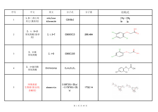
C14H15N5O6S
381.36
95
甲基代森锌(残 杀威) 氨基甲酸酯(杀 虫剂)
Propoxur
209.243
96
甲基毒死蜱
Chlorpyrifos-met hyl
C7H7Cl3NO3PS
322.53
第 16 页 共 45 页
97
甲基对硫磷 有机磷(杀虫剂)
Parathion-methy l
C8H10NO5PS
263.20
98
甲基谷硫磷
Azinphos-methyl
C10H12N3O3PS 2
317.329
99
嘧菌酯
Azoxystrobin
C22H17N3O5
403.4
100
嘧霉胺(二甲嘧 菌胺)
Pyrimethanil
C12H13N3
199.25
101
灭草松 杂环化合物(除 草剂) 灭多威 氨基甲酸酯(杀 虫剂) 灭菌丹 有机硫(杀虫剂)
47
敌百虫
trichlorfon
C4H8Cl3O4P 阳离子 C12H12N2,二溴 盐 C12H12N2Br2
第 8 页 共 45 页
48
敌草快 吡啶(除草剂)
diquat
49
敌敌畏 有机氯(杀虫剂)
Dichlorvos
C4H7Cl2O4P
220.98
50
敌菌丹 有机氯(杀虫剂)
captafol
22
吡螨胺 吡唑(杀螨剂)
tebufenpyrad
C18H24ClN3O
23
吡嘧磷
pyrazophos
373.368
24
吡蚜酮 其它(杀虫剂)
LED显示屏洲明P2.5知识讲解

洲明P2.5 LED室内全彩显示屏参数说明洲明LED显示屏体材料选择LED管芯我们经过比较,从发光亮度、色纯度、视角、光电转换率、价格、以及采用新技术等方面综合考虑,对本设备的LED管芯选择如下:设计所采用的发光像素,是我公司根据几年的设计经验以及长期合作的国内外LED灯供应商提供的最新技术资料,先后进行了多次配色实验,从性能与价格间的矛盾中寻找黄金分割最佳取向。
目前国际国内市场上LED灯品种繁多,以上品牌以其稳定的性能长寿命低衰减先进的技术在广大的显示屏幕生产厂家及最终用户中得到了一致好评,享有极高声誉。
不同的厂家、不同的材料其发光的强度、波长、半波谱带宽、温度稳定性等关键技术指标范围变化很大故选择以上品牌也可以说在针对本项目其特定的要求是相符的。
管芯参数 1光电曲线图①、视角参考此项目LED显示屏安装的位置和发光器件供应商提供的技术指标,我们严格保证屏幕系统的水平可视视角能够达到160º,上下视角大于120º;可以保证在一个较大的合理区域内分布的人群均具有较佳的观看效果。
②、波长正常情况,人的肉眼颜色分辨阀值为5nm,以红色LED为例:将两个发光波长分别为620nm和626nm的LED放在一起点亮,人的肉眼将感觉出这两个LED发出的光颜色有差异。
那么从理论上讲,一块显示屏若采用同一发光波长的LED的话问题就很好的解决了。
但是,从LED发光PN结制造来看,要批量性‘生长’(即半导体制造的一个术语)同一个波长的产品是不可能的,正常情况下一张‘生长’完成后的LED芯片其发光波长在几十个nm范围内,这个是半导体发光芯片制造工艺本身的特点。
因此,若想是一块屏保证色彩尽量一致,就必须控制同一块屏的LED芯片波长的选择范围。
③、亮度通常情况下,人的亮度分辨阀值为1:1.3,以绿色发光LED为例,将两个发光亮度分别为1000CD和1300CD的LED同时点亮放在一起,人的视觉上就感觉有差别。
MFRC522
MFRC522预付费水表、预付费燃气表、预付费热量表等接触式卡表受到环境温度、湿度、油污等外界条件的影响,大大缩短了对卡表的使用寿命,因此非接触卡表已成为当前发展趋势。
这里给出了一种基于射频器件MFRC522的智能仪表设计,提高了智能仪表的使命寿命。
1 MFRC522简介1.1 MFRC522的特点MFRC522采用串行通信方式与主机通信,可根据用户需求,选用SPI、I2C或串行UART工作模式,有利于减少连线,缩小PCB板面积,降低成本。
MFRC522主要特点如下:高度集成的调制解调电路,采用少量外部器件,即可将输出驱动级接至天线;支持ISO/IEC 14443 FypeA接口和MIFARE通信协议:支持多种主机接口:10 Mbit/s的SPI接口;I2C接口,快速模式的速率为400 Kbit/s,高速模式的速率为3 400 Kbit/s;串行UART,传输速率可以高达1 228.8 Kbit/s,帧取决于RS232接口;特有的发送器掉电机制可关闭内部天线驱动器,即关闭RF场,达到低功耗;内置温度传感器,在过热时自动停止RF发射;独立的多组电源供电,避免相互干扰,优化EMC特性和信号退耦性能;2.5 V~3.6 V的低压、低功耗,采用5 mm×5 mm×0.85 mm的超小型HVQFN32封装。
1.2 MFRC522的内部结构MFRC522的内部结构框图如图1所示。
MFRC522支持可直接相连的各种微控制器接口,如SPI、I2C 和串行UART。
MFRC522能使其接口复位自动检测上电或硬复位的当前微控制器接口类型。
可通过复位控制引脚的逻辑电平来识别微控制器接口。
数据处理部分实现数据并行一串行转换。
可支持CRC和奇偶校验。
由于MFRC522以完全透明的模式操作,因而支持ISO14443A所有层。
状态和控制部分用于配置器件,以适应环境影响并使性能达到最佳。
当MFRC522与MIFARE通信时,使用高速CRYPTO1流密码单元和一个可靠的非易失性密钥存储器。
ADSP-BF522C中文资料

a Preliminary Technical DataBlackfin and the Blackfin logo are registered trademarks of Analog Devices, Inc.Blackfin®Embedded ProcessorADSP-BF522C/ADSP-BF525C/ADSP-BF527C Rev. PrBInformation furnished by Analog Devices is believed to be accurate and reliable.However, no responsibility is assumed by Analog Devices for its use, nor for anyinfringements of patents or other rights of third parties that may result from its use. Specifications subject to change without notice. No license is granted by implication or otherwise under any patent or patent rights of Analog Devices. Trademarks and registered trademarks are the property of their respective owners.One Technology Way, P.O. Box 9106, Norwood, MA 02062-9106 U.S.A. Tel: Fax: 781.461.3113© 2007 Analog Devices, Inc. All rights reserved.FEATURESUp to 600MHz high-performance Blackfin processorTwo 16-bit MACs, two 40-bit ALUs, four 8-bit video ALUs,40-bit shifterRISC-like register and instruction model for ease ofprogramming and compiler-friendly support Advanced debug, trace, and performance monitoringtbd V to tbd V core V DD with on-chip voltage regulation1.8V,2.5V, or3.3V I/O operationEmbedded low power audio CODEC289-ball MBGA packageMEMORY132K bytes of on-chip memory:48K bytes of instruction SRAM16K bytes of instruction SRAM/cache32K bytes of data SRAM32K bytes of data SRAM/cache4K bytes of scratchpad SRAMExternal memory controller with glueless support for SDRAM and asynchronous 8-bit and 16-bit memoriesNand flash controllerFlexible booting options from external flash, SPI and TWI memory or from SPI, TWI, and UART host devicesOne-time programmable memory for securityTwo dual-channel memory DMA controllersMemory management unit providing memory protection PERIPHERALSRefer to the published ADSP-BF522/ADSP-BF525/ADSP-BF527 Revision PrB datasheet for additional peripherals CODEC FEATURESStereo 24-bit A/D and D/A convertersDAC100 dB (A-weighted) signal-to-noise ratio at 3.3 V95 dB (A-weighted) signal-to-noise ratio at 1.8 VADC90 dB (A-weighted) signal-to-noise ratio at 3.3 V85dB (A-weighted) signal-to-noise ratio at 1.8 VAudio sample rates8kHz, 44.1kHz or 88.2kHz–XTI/MCLK frequency 11.2896 MHz (256 × F S) or 16.9344 MHz (384 × F S)8kHz, 32kHz, 48kHz or 96kHz–XTI/MCLK frequency 12.288 MHz (256 × F S) or 18.432 MHz (384 × F S)Highly efficient headphone amplifierComplete stereo/mono or microphone/line interface Normal and USB modes programmed under software control Low power8mW stereo playback (1.8V all power supplies)20mW record and playback (1.8V all power supplies)) Low supply voltages1.8V to 3.6V analog supply range1.8V to 3.6V digital supply rangeFigure 1.Functional Block DiagramADSP-BF522C/ADSP-BF525C/ADSP-BF527C Preliminary Technical DataREVISION HISTORY6/07—Revision PrB: Changes from PrA to PrBCorrects SS/PG and VRSEL 289-Ball Mini-BGA Ball Assign-ment (Alphabetically by Signal) (7)Corrects SS/PG and VRSEL 289-Ball Mini-BGA Ball Assign-ment (Numerically by Ball Number) (8)3/07—Revision PrA: Initial VersionRev. PrB|Page 2 of 12|June 2007ADSP-BF522C/ADSP-BF525C/ADSP-BF527CPreliminary Technical Data Rev. PrB |Page 3 of 12|June 2007GENERAL DESCRIPTIONThis document describes the differences between the ADSP-BF522C/ADSP-BF525C/ADSP-BF527C and the ADSP-BF522/ADSP-BF525/ADSP-BF527 standard product. Please refer to the published ADSP-BF522/ADSP-BF525/ADSP-BF527 Revision PrC datasheet for general description and specifica-tions. This document only describes the exceptions to that datasheet.The ADSP-BF522C/ADSP-BF525C/ADSP-BF527C adds a ste-reo CODEC to the standard product and changes the package labeling.STEREO CODECThe CODEC in the ADSP-BF522C/ADSP-BF525C/ADSP-BF527C is a low power, high quality stereo audio CODEC for portable digital audio application. It features two 24-bit A/D converter channels and two 24-bit D/A converter channels.In normal mode, the XMI/MCLK oscillator is set up according to the desired sample rates of the ADC and DAC. For ADC or DAC sampling rates of 8 kHz, 32 kHz, 48 kHz or 96 kHz, MCLK frequencies of either 12.288 MHz (256 × FS) or 18.432 MHz (384 × FS) can be used. For ADC or DAC sampling rates of 8kHz, 44.1 kHz or 88.2 kHz, MCLK frequencies of either 11.2896 MHz (256 × FS) or 16.9344 MHz (384 × FS) can be used.In USB mode, the XTI/MCLK frequency is only 12MHz allow-ing for ADC and DAC sampling rates of 8kHz, 44.1 kHz or 88.2 kHz.The CODEC can operate with power supplies as low as 1.8V for the analog part and 1.8V for digital port. The maximum voltage is 3.6V for all power supplies.The device is controlled by a 2- or 3-wire serial interface which provides access to all features including volume controls, mutes and extensive power management facilities.Figure 2.Audio CODEC Block DiagramADSP-BF522C/ADSP-BF525C/ADSP-BF527C Preliminary Technical DataPIN DESCRIPTIONSThe ADSP-BF522C/ADSP-BF525C/ADSP-BF527C processoradds CODEC signals as listed in Table1.Table 1.Pin DescriptionsPin Name Type Function Pull-Up/DownCCLKOUT O CODEC Clock Output NoneBCLK I/O CODEC Digital Audio Bit Clock Internal Pull-down1 DACDAT I CODEC DAC Sample Rate Left/Right Clock NoneDACLRC I/O CODEC I/O DAC Sample Rate Left/Right Clock Internal Pull-down1 ADCDAT O CODEC ADC Digital Audio Data Output NoneADCLRC I/O CODEC ADC Sample Rate Left/Right Clock Internal Pull-down1CMODE I CODEC Control Interface Selection Internal Pull-up1CSB I CODEC MPU Chip Select/MPU Interface Address Selection Internal Pull-up1CSDA I/O CODEC MPU Data Input NoneCSCL I CODEC MPU Clock NoneXTI/MCLK I CODEC Crystal Input/MPU Clock Input NoneXTO O CODEC Crystal Output NoneLHPOUT O CODEC Left Channel Headphone Output (Analog Output)NoneRHPOUT O CODEC Right Channel Headphone Output (Analog Output)NoneLOUT O CODEC Left Channel Line Output (Analog Output)NoneROUT O CODEC Right Channel Line Output (Analog Output)NoneVMID O CODEC Mid-rail Reference Decoupling Point (Analog Output)NoneMICBIAS O CODEC Electret Microphone Bias (Analog Output)NoneMICIN I CODEC Microphone Input; (Analog Input, AC Coupled)NoneRLINEIN I CODEC Right Channel Line Input (Analog Input, AC Coupled)NoneLLINEIN I CODEC Left Channel Line Input (Analog Input, AC Coupled)NoneGND P CODEC Digital Core Ground N/AAVDD P CODEC Analog V DD N/AAGND P CODEC Analog Ground N/AHPVDD P CODEC Headphone V DD (Analog)N/AHPGND P CODEC Headphone Ground N/A1Pull-up/pull-down is only present when the control register interface ACTIVE = 0 to conserve power.Rev. PrB|Page 4 of 12|June 2007ADSP-BF522C/ADSP-BF525C/ADSP-BF527CPreliminary Technical Data Rev. PrB |Page 5 of 12|June 2007SPECIFICATIONSComponent specifications are subject to change without notice.OPERATING CONDITIONSELECTRICAL CHARACTERISTICSParameter Conditions Min TypicalMax Unit CV DD Digital Core V DD 1.8 3.6V AV DD Analog V DD 1.8 3.6V HPV DD Headphone V DD (Analog) 1.8 3.6V V ILC CODEC Low Level Input Voltage 11Parameter value applies to digital signal pins (ADCDAT, ADCLRC, BCLK, CSB, CCLKOUT, CMODE, DACDAT, DACLRC, CSCL, CSDA, XTI/MCLK, XTO).0.3 × CV DD V V IHC CODEC High Level Input Voltage 10.7 × CV DDV V OLC CODEC Low Level Output Voltage 10.1 × CV DDV V OHC CODEC Low Level Output Voltage 10.9 × CV DD V T J Junction Temperature 289-Ball Chip Scale Ball Grid Array (Mini-BGA)@ T AMBIENT = 0°C to +70°C+105°CParameter Conditions Min Typical MaxUnit Line Input to ADC SNR Signal to Noise Ratio A-weighted, 0 dB Gain @ F S = 48kHz tbd 85dB SNR Signal to Noise Ratio A-weighted, 0 dB Gain @ F S = 96kHz 85dB DR Dynamic Range A-weighted, –60 dB Full Scale Input tbd88dB THD Total Harmonic Distortion –1 dB Input, 0 dB Gain –76tbddB Microphone Input to ADC 0 dB Gain, F S = 48kHz, 40k Ω Source Impedance SNR Signal to Noise Ratio A-weighted, 0 dB Gain 80dB DR Dynamic Range A-weighted, –60 dB Full Scale Input 70dB THD Total Harmonic Distortion 0 dB Input, 0 dB Gain –55dB Line Output for DAC Playback Only Load = 10k Ω, 50 pF SNR Signal to Noise Ratio A-weighted, 0 dB Gain @ F S = 48kHz tbd 95dB SNR Signal to Noise Ratio A-weighted, 0 dB Gain @ F S = 96kHz 93dB DR Dynamic Range A-weighted, –60 dB Full Scale Input tbd90dB THD Total Harmonic Distortion 1kHz, 0 dB –80tbddB THD Total Harmonic Distortion 1kHz, –3 dB–90dB Analog Line Input to Line Output Load = 10k Ω, 50 pF, No Gain on Input, Bypass Mode SNR Signal to Noise Ratio tbd90dB THD Total Harmonic Distortion 1kHz, 0 dB –83tbddB THD Total Harmonic Distortion 1kHz, –3 dB –92dB Stereo Headphone Output PO Maximum Output Power R L = 32 Ω9mW PO Maximum Output Power R L = 16 Ω18mW SNR Signal to Noise Ratio A-weighted tbd95dB THD Total Harmonic Distortion 1kHz, –5 dB, R L = 32 Ω, Full Scale Input –62tbd dB THD Total Harmonic Distortion 1kHz,–2 dB, R L = 32 Ω, Full Scale Input tbddB Microphone Input to Headphone Output Side Tone Mode SNR Signal to Noise Ratiotbd 90dBRev. PrB |Page 6 of 12|June 2007ADSP-BF522C/ADSP-BF525C/ADSP-BF527CPreliminary Technical DataDIGITAL FILTER CHARACTERISTICSPACKAGE INFORMATIONThe information presented in Figure 3 and Table 2 provides details about the package branding for the ADSP-BF522C/ADSP-BF525C/ADSP-BF527C processor. For a com-plete listing of product availability, see Ordering Guide on Page 12.Parameter Conditions Min Typical Max UnitADC Filter Passband ±0.05 dB tbd × F Stbd × F SPassband–6 dB0.5 × F SPassband Ripple tbddB Stopbandtbd × F S Stopband AttenuationF > 0.5465 × F S tbddB High Pass Filter Corner Frequency –3 dB 3.7Hz High Pass Filter Corner Frequency –0.5 dB 10.4Hz High Pass Filter Corner Frequency –0.1 dB 21.6HzDAC Filter Passband ±0.03 dB tbd × F Stbd × F SPassband–6 dB0.5 × F SPassband Ripple tbddB Stopbandtbd × F S Stopband AttenuationF > 0.5465 × F Stbd dBFigure 3.Product Information on PackageTable 2.Package Brand InformationBrand KeyField Descriptiont Temperature Range pp Package Type Z Lead Free Option ccc See Ordering Guide vvvvvv.x Assembly Lot Code n.n Silicon Revision yywwDate CodeADSP-BF522C/ADSP-BF525C/ADSP-BF527CPreliminary Technical Data Rev. PrB |Page 7 of 12|June 2007289-BALL MINI-BGA PINOUTTable 3 lists the mini-BGA pinout by signal mnemonic. Table 4 on Page 8 lists the mini-BGA pinout by ball number.Table 3.289-Ball Mini-BGA Ball Assignment (Alphabetically by Signal)SignalBall No.SignalBallNo.Signal Ball No.Signal Ball No.Signal Ball No.Signal Ball No.Signal Ball No.ABE0/SDQM0AB9CSB D23GNDL14PF5B10RESET V22VDDEXT R17VDDMEM U8ABE1/SDQM1AC9CSCL B23GND L15PF6B12RHPOUT B21VDDEXT T17VDDMEM U9ADCDAT A16CSDA C23GND M9PF7B13RLINEIN F23VDDEXT U17VDDMEM U10ADCLRC A15DACDAT A18GND M10PF8B16ROUT G22VDDINT B5VDDMEM U11ADDR1AB8DACLRC A17GND M11PF9A20RTXI U23VDDINT H8VDDMEM U12ADDR2AC8DATA0Y1GND M12PF10B15RTXO V23VDDINT H9VDDMEM U13ADDR3AB7DATA1V2GND M13PF11B17SA10AC10VDDINT H10VDDMEM U14ADDR4AC7DATA2W1GND M14PF12B18SCAS AC11VDDINT H11VDDMEM U15ADDR5AC6DATA3U2GND M15PF13B19SCKE AB13VDDINT H12VDDMEM U16ADDR6AB6DATA4V1GND N9PF14A9SCL B22VDDINT H13VDDOTP AC12ADDR7AB4DATA5U1GND N10PF15A10SDA C22VDDINT H14VDDRTC W23ADDR8AB5DATA6T2GND N11PG0H2SMS AC13VDDINT H15VDDUSB W22ADDR9AC5DATA7T1GND N12PG1G1SRAS AB12VDDINT H16VDDUSB Y23ADDR10AC4DATA8R1GND N13PG2H1SS/PG AC20VDDINT J8VMID G23ADDR11AB3DATA9P1GND N14PG3F1SWE AB10VDDINT J16VROUT AC18ADDR12AC3DATA10P2GND N15PG4D1TCK L1VDDINT K8VRSEL AB22ADDR13AB2DATA11R2GND P9PG5D2TDI J1VDDINT K16XTAL P23ADDR14AC2DATA12N1GND P10PG6C2TDO K1VDDINT L8XTI/MCLK A22ADDR15AA2DATA13N2GND P11PG7B1TMS L2VDDINT L16XTOA21ADDR16W2DATA14M2GND P12PG8C1TRST K2VDDINT M8ADDR17Y2DATA15M1GND P13PG9B2USB_DM AB21VDDINT M16ADDR18AA1EMU J2GND P14PG10B4USB_DP AA22VDDINT N8ADDR19AB1EXT_WAKE AC19GND P15PG11B3USB_ID Y22VDDINT N16AGND G17GND A1GND R9PG12A2USB_RSET AC21VDDINT P8AGND H22GND A23GND R10PG13A3USB_VBUS AB20VDDINT P16AMS0AC17GND B6GND R11PG14A4USB_VREF AC22VDDINT R8AMS1AB16GND J9GND R12PG15A5USB_XTALIN AB23VDDINT R16AMS2AC16GND J10GND R13PH0A11USB_XTALOUT AA23VDDINT T8AMS3AB15GND J11GND R14PH1A12VDDEXT G7VDDINT T9AOE AC15GND J12GND R15PH2A13VDDEXT G8VDDINT T10ARDY AC14GND J13GND T22PH3B14VDDEXT G9VDDINT T11ARE AB17GND J14GND AC1PH4A14VDDEXT G10VDDINT T12AVDD G16GND J15GND AC23PH5K23VDDEXT G11VDDINT T13AVDD J22GND K9LHPOUT B20PH6K22VDDEXT G12VDDINT T14AWE AB14GND K10LLINEIN E23PH7L23VDDEXT G13VDDINT T15BCLK A19GND K11LOUT F22PH8L22VDDEXT G14VDDINT T16BMODE0G2GND K12MICBIAS H23PH9T23VDDEXT G15VDDMEM J7BMODE1F2GND K13MICIN J23PH10M22VDDEXT H7VDDMEM K7BMODE2E1GND K14NMI U22PH11R22VDDEXT H17VDDMEM L7BMODE3E2GND K15OTPVPP AB11PH12M23VDDEXT J17VDDMEM M7CCLKOUT D22GND L9PF0A7PH13N22VDDEXT K17VDDMEM N7CLKBUF AB19GND L10PF1B8PH14N23VDDEXT L17VDDMEM P7CLKIN R23GND L11PF2A8PH15P22VDDEXT M17VDDMEM R7CLKOUT AB18GND L12PF3B9PPICLK/TMRCLK A6VDDEXT N17VDDMEM T7CMODE E22GND L13PF4B11PPIFS1/TMR0B7VDDEXTP17VDDMEMU7ADSP-BF522C/ADSP-BF525C/ADSP-BF527C Preliminary Technical Data Table 4.289-Ball Mini-BGA Ball Assignment (Numerically by Ball Number)Ball No.Signal BallNo.Signal BallNo.Signal BallNo.Signal BallNo.Signal BallNo.Signal BallNo.SignalA1GND B23CSCL H22AGND L22PH8P22PH15U22NMI AC5ADDR9A2PG12C1PG8H23MICBIAS L23PH7P23XTAL U23RTXI AC6ADDR5A3PG13C2PG6J1TDI M1DATA15R1DATA8V1DATA4AC7ADDR4A4PG14C22SDA J2EMU M2DATA14R2DATA11V2DATA1AC8ADDR2A5PG15C23CSDA J7VDDMEM M7VDDMEM R7VDDMEM V22RESET AC9ABE1/SDQM1 A6PPICLK/TMRCLK D1PG4J8VDDINT M8VDDINT R8VDDINT V23RTXO AC10SA10A7PF0D2PG5J9GND M9GND R9GND W1DATA2AC11SCASA8PF2D22CCLKOUT J10GND M10GND R10GND W2ADDR16AC12VDDOTPA9PF14D23CSB J11GND M11GND R11GND W22VDDUSB AC13SMSA10PF15E1BMODE2J12GND M12GND R12GND W23VDDRTC AC14ARDYA11PH0E2BMODE3J13GND M13GND R13GND Y1DATA0AC15AOEA12PH1E22CMODE J14GND M14GND R14GND Y2ADDR17AC16AMS2A13PH2E23LLINEIN J15GND M15GND R15GND Y22USB_ID AC17AMS0A14PH4F1PG3J16VDDINT M16VDDINT R16VDDINT Y23VDDUSB AC18VROUTA15ADCLRC F2BMODE1J17VDDEXT M17VDDEXT R17VDDEXT AA1ADDR18AC19EXT_WAKEA16ADCDAT F22LOUT J22AVDD M22PH10R22PH11AA2ADDR15AC20SS/PGA17DACLRC F23RLINEIN J23MICIN M23PH12R23CLKIN AA22USB_DP AC21USB_RSETA18DACDAT G1PG1K1TDO N1DATA12T1DATA7AA23USB_XTALOUT AC22USB_VREFA19BCLK G2BMODE0K2TRST N2DATA13T2DATA6AB1ADDR19AC23GNDA20PF9G7VDDEXT K7VDDMEM N7VDDMEM T7VDDMEM AB2ADDR13A21XTO G8VDDEXT K8VDDINT N8VDDINT T8VDDINT AB3ADDR11A22XTI/MCLK G9VDDEXT K9GND N9GND T9VDDINT AB4ADDR7A23GND G10VDDEXT K10GND N10GND T10VDDINT AB5ADDR8B1PG7G11VDDEXT K11GND N11GND T11VDDINT AB6ADDR6B2PG9G12VDDEXT K12GND N12GND T12VDDINT AB7ADDR3B3PG11G13VDDEXT K13GND N13GND T13VDDINT AB8ADDR1B4PG10G14VDDEXT K14GND N14GND T14VDDINT AB9ABE0/SDQM0B5VDDINT G15VDDEXT K15GND N15GND T15VDDINT AB10SWEB6GND G16AVDD K16VDDINT N16VDDINT T16VDDINT AB11OTPVPPB7PPIFS1/TMR0G17AGND K17VDDEXT N17VDDEXT T17VDDEXT AB12SRASB8PF1G22ROUT K22PH6N22PH13T22GND AB13SCKEB9PF3G23VMID K23PH5N23PH14T23PH9AB14AWEB10PF5H1PG2L1TCK P1DATA9U1DATA5AB15AMS3B11PF4H2PG0L2TMS P2DATA10U2DATA3AB16AMS1B12PF6H7VDDEXT L7VDDMEM P7VDDMEM U7VDDMEM AB17AREB13PF7H8VDDINT L8VDDINT P8VDDINT U8VDDMEM AB18CLKOUTB14PH3H9VDDINT L9GND P9GND U9VDDMEM AB19CLKBUFB15PF10H10VDDINT L10GND P10GND U10VDDMEM AB20USB_VBUSB16PF8H11VDDINT L11GND P11GND U11VDDMEM AB21USB_DMB17PF11H12VDDINT L12GND P12GND U12VDDMEM AB22VRSELB18PF12H13VDDINT L13GND P13GND U13VDDMEM AB23USB_XTALINB19PF13H14VDDINT L14GND P14GND U14VDDMEM AC1GNDB20LHPOUT H15VDDINT L15GND P15GND U15VDDMEM AC2ADDR14B21RHPOUT H16VDDINT L16VDDINT P16VDDINT U16VDDMEM AC3ADDR12B22SCL H17VDDEXT L17VDDEXT P17VDDEXT U17VDDEXT AC4ADDR10Rev. PrB|Page 8 of 12|June 2007ADSP-BF522C/ADSP-BF525C/ADSP-BF527CPreliminary Technical DataRev. PrB |Page 9 of 12|June 2007Figure 5 shows the top view of the mini-BGA ball configuration. Figure 4 shows the bottom view of the mini-BGA ball configuration.Table 5.Thermal Characteristics (BC-289)Parameter ConditionTypical Unit θJA 0 linear m/s air flow tbd ؇C/W θJMA 1 linear m/s air flow tbd ؇C/W θJMA 2 linear m/s air flowtbd ؇C/W θJB tbd ؇C/W θJCtbd؇C/WFigure 4.289-Ball Mini-BGA Ball Configuration (Top View)Rev. PrB |Page 10 of 12|June 2007ADSP-BF522C/ADSP-BF525C/ADSP-BF527CPreliminary Technical DataFigure 5.289-Ball Mini-BGA Ball Configuration (Bottom View)ADSP-BF522C/ADSP-BF525C/ADSP-BF527CPreliminary Technical Data Rev. PrB |Page 11 of 12|June 2007OUTLINE DIMENSIONSDimensions in the outline dimension figures are shown in millimeters.SURFACE MOUNT DESIGNTable 6 is provided as an aid to PCB design. For industry-standard design recommendations, refer to IPC-7351,Generic Requirements for Surface Mount Design and Land Pat-tern Standard .Figure 6.289-Ball Chip Scale Package Ball Grid Array (Mini-BGA)Table 6.BGA Data for Use with Surface Mount DesignPackageBall Attach Type Solder Mask Opening Ball Pad Size289-Ball Chip Scale Package Ball Grid Array (Mini-BGA)Solder Mask Defined0.26 mm diameter0.35 mm diameterRev. PrB |Page 12 of 12|June 2007ADSP-BF522C/ADSP-BF525C/ADSP-BF527CPreliminary Technical Data©2007 Analog Devices, Inc. All rights reserved. Trademarks and registered trademarks are the property of their respective owners.PR06876-0-6/07(PrB)ORDERING GUIDEModel Temperature Range 11Referenced temperature is ambient temperature.Package Description Package Option Instruction Rate (Max)Operating Voltage(Nom)ADSPBF527KBCZENGC1 0ºC to +70ºC 289-Ball Chip Scale Package Ball Grid Array (Mini-BGA)BC-289600 MHz tbd V internal, 1.8 V or 3.3 V I/O。
限制性液体复苏在失血性休克患者复苏早期的应用价值
限制性液体复苏在失血性休克患者复苏早期的应用价值秦朴;蔡云刚;易晓淑;秦亚伟;张义;余成艳【摘要】目的:探讨限制性液体复苏在失血性休克患者复苏早期的应用价值。
方法采取随机双盲对照研究方法将181例出血未控制的失血性休克患者分为对照组(86例)和治疗组(95例)。
对照组在复苏早期行积极容量复苏,治疗组采取限制性液体复苏策略,出血控制后再行积极容量复苏。
观察两组的抢救成功率、死亡率、多器官功能障碍综合征(M ODS )发生率及住院时间等指标。
结果治疗组抢救成功率高于对照组(P<0.05),MODS发生率、死亡率低于对照组(P<0.05),平均住院时间短于对照组(P<0.05)。
结论失血性休克患者复苏早期采取限制性液体复苏策略较积极容量复苏更优,值得临床推广应用。
【期刊名称】《重庆医学》【年(卷),期】2015(000)004【总页数】2页(P522-523)【关键词】休克 ,出血性;积极容量复苏;限制性液体复苏【作者】秦朴;蔡云刚;易晓淑;秦亚伟;张义;余成艳【作者单位】重庆市丰都县人民医院急诊科 408200;重庆市丰都县人民医院重症医学科 408200;重庆市丰都县人民医院医务科 408200;重庆市丰都县人民医院急诊科 408200;重庆市丰都县人民医院急诊科 408200;重庆市丰都县人民医院急诊科 408200【正文语种】中文【中图分类】R459.71.1 一般资料选择本院2010年3月至2013年2月院前急救接诊的失血性休克患者181例。
181例患者接诊时均符合失血性休克的诊断标准[2],且无严重心、肺、脑、肾基础疾病,采用随机双盲对照研究将181例患者分为两组。
对照组86例,其中男52例,女34例;年龄15~75岁,平均50.2岁;创伤出血61例,消化道出血14例,异位妊娠出血5例,其他病例6例。
治疗组95例,其中男59例,女36例;年龄14~75岁,平均53.6岁;创伤出血68例,消化道出血13例,异位妊娠出血6例,其他病例8例。
BBS-SP2W资料
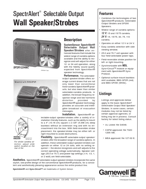
SpectrAlert® Selectable Output Wall Speaker/Strobes CS-2452 10/21/04Page 1 of 2For strobe candela se-lection, adjust slide switch located on the rear of theDescriptionSystemSensor SpectrAlert®Selectable Output WallSpeaker/Strobes offer en-hanced features that include thewidest range of candela optionsavailable and the ability to rec-ognize and self-adjust for either12- or 24-volt operation, alongwith the fidelity sound qualityexpected from SpectrAlert®speaker technology.Performance. The selectable-output speaker/strobe offers av-erage current draws that are notonly lower than conventionalfixed-candela SpectrAlert® prod-ucts, but also lower than similarselectable-candela products. Inaddition, the broad-frequency re-sponse range and low harmonicdistortion provided bySpectrAlert® speaker technologyprovides an accurate and intelli-gible broadcast of evacuationmessages.Installation. SpectrAlert® se-lectable-output speaker/strobes offer a variety of in-stallation-friendly features, such as the ability to mountto a 4" (10.16 cm) square x 2.125" (5.398 cm) deepbackbox without an extension ring and with no en-croachment into the box. With field-reversible strobeplacement, the speaker/strobe may be either left- orright-mounted to avoid obstructions.Flexibility. SpectrAlert® selectable-output speaker/strobes offer the broadest range of candela options. In addition, these selectable-output speaker/strobes can operate on either 12 or 24 volts, with no setting re-quired — the device recognizes and self-adjusts to thecorrect operating voltage automatically. Speaker volt-age (25.0 or 70.7) and power tap settings (1/4, 1/2, 1,or 2 watt) are field-selectable.Aesthetics. SpectrAlert® selectable-output speaker/strobes incorporate the same stylish, low-profile design of the conventional SpectrAlert® products, for a consis-tent and aesthetically pleasing appearance across the entire product line .SpectrAlert® and Sync•Circuit™ are trademarks of System Sensor.6943pho1.jpg SP2R1224MCSpectrAlert® Selectable Output Wall Speaker/Strobes CS-2452 10/21/04Page 2 of 2Specifications and wiring information are provided for information only and are believed to be accurate. Gamewell assumes no responsibility for their use.Data and design are subject to change without notice. Installation and wiring instructions shipped with the product shall always be used for actual installation. For more information, contact Gamewell.Gamewell12 Clintonville Road Northford, CT 06472-1610Phone: 203-484-7161Fax: 203-484-7118A Honeywell Company© 2004 Gamewell Engineering SpecificationsSpeaker/Strobe shall be a System Sensor model _____ Listed to UL1480 and UL 1971 and be approved for fire protective signaling systems. Speaker shall be capable of operating at 25.0 or 70.7 nominal V RMS , and shall have a frequency range of 400 – 4000 Hz. Speaker shall have power taps that are selected by DIP switch. The strobe shall consist of a xenon flash tube with associated lens/re-flector system and operate on either 12 volts or 24 volts. The strobe shall also feature selectable-candela output, providing options for 15 or 15/75 candela when operating on 12 volts; and 15, 15/75, 30, 75, or 110 when operating on 24 volts.The strobe shall comply with the Americans with Disabilities Act requirement for visible signaling appliances, flashing at 1 Hz over the strobe’s entire operating voltage range.Ordering InformationSound Output。
TS522ID资料

Dim. A a1 a2 a3 b b1 C c1 D E e e3 F L M S
Min. 0.1 0.65 0.35 0.19 0.25 4.8 5.8
Millimeters Typ.
Max. 1.75 0.25 1.65 0.85 0.48 0.25 0.5 45o (typ.) 5.0 6.2
Value ±18 or +36 ±30 ±15 Infinite -40 to +105 +150 -65 to +150 500
Unit V V V
o o o
C C C
mW
1. Either or both input voltages must not exceed the magnitude of VCC+ or VCC2. Power dissipation must be considered to ensure maximum junction temperature (Tj) is not exceeded
OPERATING CONDITIONS
Symbol VCC Supply Voltage Parameter Value ±2.5 to ±15 Unit V
2/5
元器件交易网
TS522
ELECTRICAL CHARACTERISTICS VCC+ = +15V, VCC- = -15V, Tamb = 25oC (unless otherwise specified)
3/5
元器件交易网
TS522
PACKAGE MECHANICAL DATA 8 PINS - PLASTIC DIP
Dim. A a1 B b b1 D E e e3 e4 F i L Z
理光2105代码

理光复印机进SP模式/ID传感器2011-01-25 08:29勿让用户进入SP模式,只有维修代理人员允许进入SP 模式.如果维修代理人员之外的其他人进入了SP模式后,就不能保证机器的质量及运行。
(1)使用SP模式可以获得以下两个模式:A、SP模式(维修编程模式):SP模式包括了维护工作所需的编程。
B、SSP模式(特殊SP模式):SSP模式包括了SP模式编程及一些特殊编程。
你需有一些另外的知识来操作这些特殊编程。
至于详情,咨询你的上级主管。
启动SP模式1、键入以下键:清除键、1、0、72、按住停止键直到显示出SP模式菜单(约3秒钟)。
启动SSP模式对于基础机器(没有可选的控制器盒),按1到4步骤所列的执行。
对于多功能机器(有可选的控制器盒),按1到5步骤所列的执行1、键入以下键:清除键、1、0、72、按住停止键直到显示出SP模式菜单(约3秒钟)。
3、按住 # 号键。
4、按下 # 号键的同时按下 1 键(在数字小键盘上)。
5、按下 # 号键时按“OK”键。
选择编程1、当显示出闪烁的下划线(或由几条闪烁下划线),你可从数字小键盘上输入数字。
2、当右上角显示出:“《》/OK”符号时,按左箭头键或右箭头键来滚动菜单。
要选择程序,按OK键。
指定值1、找到编程后,按OK键。
闪烁下划线显示出你可改变那个值。
括号中的值是菜单的默认值。
2、从数字小键盘上输入必要的值。
要在正(负)和(减)之间变换,按“开始”键。
3、要使值生效,按OK键。
要取消值,按“取消”键。
激活复印模式SP模式在运行时,你可激活复印模式。
当你这样做时,复印机打印输出图形或图像,以帮助你调整SP模式编程。
1、按“开始”键,激活复印模式。
2、指定复印设定值,并按“开始”键。
3、要返回到SP模式,按“清除”键。
注意:激活复印模式时,你不能结束SP模式。
退出编程/结束(S)SP 模式按“清除”键或取消键来退出编程。
多次按这些键的其中一个来结束SP 模式。
图集编号-规则..

“才能根植于骨髓,知识依赖于积累”国家图集编号规则(韩英哲)国家建筑标准设计图集分不同专业、不同代号,每个专业又分标准图、试用图、参考图、合订本等类型。
国家标准图集编号D--电气图集; F--人防工程图集; G--结构图集;J--建筑图集; K--暖通图集;SG--民用结构M--市政路桥图集; R--动力专业图集; S--给排水图集;X--弱电图集;SR--动力供热安装SS--水设备安装前面加C指重复使用图,前面加S指试用图,如04CJ01-1 02SS405-1。
编号方法1985年以后,国家建筑标准设计的编号由批准年代号、专业代号、类别号、顺序号、分册号组成,例如:02SS405-1 参考----↓专业顺序号[0][2][C][S][S][4][0][5]-[1]←--分册号批准年试用类别03G101-1批准年代号(合订本无此项,批准年代号显示在分册中)结构专业代号(试用图为SG)(参考图为CG)图集类别号(参见下表)顺序号分册号(无分册时无此号)类别号的编号与类别对应表:0→表示总图及室外工程;1→表示墙体;2→表示屋面;3→表示楼地面;4→表示楼梯;5→表示装修;6→表示门窗及天窗;7→表示---;8→表示设计图示;9→表示综合项目。
编号类别编号类别1制图规则及设计深度5钢结构构件及构造2构筑物6砌体构件构造3钢筋混凝土构件及构造7新型墙体材料构件及构造4预应力混凝土构件及构造地方标准图集编号“省简称+发行年份+标准编号+图序号”或“发行年份+省简称+标准编号+图序号”或“发行年份+省简称第一个大写字母+标准编号+图序号”如陕西省的建筑标准图集编号为“陕02J02 ”,浙江省的建筑图集为“97浙TJ1”,河南省建筑标准图集编号 05YJ为方便大家查找,在整理资料时把资料按照编号规范进行整理。
在搜索的时候可以直接搜索图集编号或按图集分类查询。
如搜索国标03G101-1,建议搜索“G101”。
- 1、下载文档前请自行甄别文档内容的完整性,平台不提供额外的编辑、内容补充、找答案等附加服务。
- 2、"仅部分预览"的文档,不可在线预览部分如存在完整性等问题,可反馈申请退款(可完整预览的文档不适用该条件!)。
- 3、如文档侵犯您的权益,请联系客服反馈,我们会尽快为您处理(人工客服工作时间:9:00-18:30)。
The SP522/524 is a monolithic device that supports three serial interface standards for Wide Area Network Connectivity. The SP522/524 is ideally suited for multi-protocol designs that are cost and space sensitive. The SP522/524 is fabricated using a low power BiCMOS process technology. Two (2) drivers and two (2) receivers for the SP522 can be configured via software for any of the above interface modes at any time. The SP524 offers two (2) additional drivers and two (2) additional receivers.■ SP522 — 2 Drivers and 2 Receivers ■ SP524 — 4 Drivers and 4 Receivers ■Driver and Receiver Tri-State Control ■ Low-Cost WAN Solution■ Loopback Function for Diagnostics ■ Software Selectable Interface Modes:-RS-232 (V.28), RS-423 (V.10)-RS-422 (V.11, X.21), RS-485DESCRIPTIONSPECIFICATIONSTypical @ 25°C and nominal supply voltages unless otherwise noted.MIN.TYP.MAX.UNITS CONDITIONSLOGIC INPUTS V IL 0.8Volts V IH2.0Volts LOGIC OUTPUTS V OL 0.4Volts I OUT = –3.2mA V OH2.4VoltsI OUT = 1.0mARS422 DRIVER TTL Input Levels V IL 00.8Volts V IH 2.0Volts OutputsDifferential Output+2.0+5.0Volts R=50Ω; see Figure 1Open Circuit Voltage,V O +6.0Volts Balance +0.4Volts |V T | – |V T |Offset+3.0Volts Short Circuit Current +150mA V out = 0VPower Off Current +100µA V cc = 0V, V out = +0.25V Transition Time40nS Rise/fall time, 10%-90%Max. Transmission Rate 10Mbps R L =100ΩPropagation Delay T A = +25°Ct PHL 90150nS R DIFF =100Ω, Figures 3 & 5 t PLH90150nSR DIFF =100Ω, Figures 3 & 5RS422 RECEIVER TTL Output Levels V OL 0.4Volts V OH 2.4Volts InputHigh Threshold +0.3+6.0Volts (a)-(b)Low Threshold-6.0-0.3Volts (a)-(b)Common Mode Range -7.0+7.0Volts High Input Current Refer to Rec. input graph Low Input Current Refer to Rec. input graph Receiver Sensitivity +0.3Volts V CM = +7V to -7V Input Impedance 4k ΩMax. Transmission Rate 10Mbps Propagation Delay T A = +25°C t PHL 110175nS Figures 3 & 7 t PLH110175nSFigures 3 & 7RS485 DRIVER TTL Input Levels V IL 0.8Volts V IH 2.0Volts OutputsDifferential Output+1.5+5.0Volts R=27Ω; C L =50pF; see Fig. 1Open Circuit Voltage,V O +6.0Volts Balance+0.2Volts |V T | – |V T |Output Current28.0mA R L =54ΩShort Circuit Current +200mA V out = –7V to +7VTransition Time40nS Rise/fall time, 10%-90%Max. Transmission Rate 10Mbps R L =54ΩPropagation Delay Figures 3 & 5; T A = +25°C t PHL 100150nS R DIFF =54Ω, C RL = 50pF t PLH100150nSR DIFF =54Ω, C RL = 50pFSPECIFICATIONSTypical @ 25°C and nominal supply voltages unless otherwise noted.MIN.TYP.MAX.UNITS CONDITIONSRS485 RECEIVER TTL Output Levels V OL 0.4Volts V OH 2.4Volts InputCommon Mode Range -7.0+12.0Volts High Input Current Refer to Rec. input graph Low Input Current Refer to Rec. input graph Receiver Sensitivity ±0.1Volts V CM = +12V to -7V Input Impedance 12k ΩV CM = +12V to -7V Max. Transmission Rate 10Mbps Propagation Delay T A = +25°C t PHL 110175nS Figures 3 & 7 t PLH110175nSFigures 3 & 7RS232 DRIVER TTL Input Level V IL 0.8Volts V IH 2.0Volts OutputsHigh Level Output +5.0+15Volts R L =3K Ω, V IN =0.8V Low Level Output -15.0-5.0Volts R L =3K Ω, V IN =2.0V Open Circuit Voltage -15+15Volts Short Circuit Current +100mA V out = 0VPower Off Impedance 300ΩV cc = 0V, V out = ±2.0V Slew Rate30V/µs R L =3K Ω, C L =50pF,between +3V to –3V Transition Time1.5µs R L =3K Ω, C L =2500pF Max. Transmission Rate 120Kbps R L =3K Ω, C L =2500pF Propagation Delay T A = +25°C t PHL 28µS R L =3K Ω t PLH28µSR L =3K ΩRS232 RECEIVER TTL Output Levels V OL 0.4Volts V OH 2.4Volts InputHigh Threshold 1.7 3.0Volts Low Threshold0.8 1.2Volts Receiver Open Circuit Bias +2.0Volts Input Impedance 357K ΩMax. Transmission Rate 120Kbps Propagation Delay T A = +25°Ct PHL 0.21µS t PLH0.21µSRS423 DRIVER TTL Input Levels V IL 0.8Volts V IH 2.0Volts OutputV DD = +5V, V SS = –5V High Level Output +3.6+6.0Volts R L =450Ω, V T = 0.9*V OC Low Level Output -6.0-3.6Volts R L =450Ω, V T = 0.9*V OC Open Circuit Voltage +4.0+6.0Volts Short Circuit Current+150mAV OUT = 0VV.10 RECEIVERRS485 RECEIVERV.11 RECEIVERRECEIVER INPUT GRAPHSSPECIFICATIONS (Continued)ABSOLUTE MAXIMUM RATINGSThese are stress ratings only and functional operation of the device at these ratings or any other above those indicated in the operation sections of the specifications below is not implied. Exposure to absolute maximum rating conditions for extended periods of time may affect reliability.V CC ............................................................................+7V V DD ........................................................................+12V V SS ..........................................................................–12V Input VoltagesLogic...............................-0.5V to (V CC +0.5V)Drivers............................-0.5V to (V CC +0.5V)Receivers..........................±30V@≤100mAOutputs VoltagesLogic................................-0.5V to (V CC +0.5V)Drivers................................................+15V Receivers........................-0.5V to (V CC +0.5V)Storage Temperature..........................-65˚C to +150˚C Power Dissipation.........................................2000mWOTHER AC CHARACTERISTICS(Typical @ 25°C and nominal supply voltages unless otherwise noted)Figure 1. Driver DC Test Load Circuit Figure 2. Receiver Timing Test Load CircuitFigure 3. Driver/Receiver Timing Test Circuit Figure 4. Driver Timing Test Load #2 Circuit ArrayFigure 5. Driver Propagation DelaysFigure 6. Driver Enable and Disable TimesFigure 7. Receiver Propagation DelaysFigure 8. Receiver Enable and Disable TimesPINOUT (24-PIN SOIC & SSOP)PINOUT (44-PIN QFP)元器件交易网FEATURESThe SP522 and SP524 is a highly integrated serial transceiver that offers programmability between interface modes through software con-trol. The SP522 and SP524 offers the hardware interface modes for RS-232 (V.28), RS-422A (V.11), RS-423 (V.10), and RS-485. The inter-face mode selection is done via two control pins. The SP522 contains two (2) independent drivers and two (2) independent receivers. The SP524 is basically two SP522 functions on one silicon, thus having four (4) drivers and four (4) receivers.The SP522/SP524 is ideally suited for low-cost wide area network connectivity and other multi-protocol applications. Based on our previous multi-mode SP500 family, Sipex has allocated specific transceiver cells or "building blocks" from the SP503 and created the SP522. The "building block" concept is that these small transceiver cells can be packaged to offer a simple low-cost solution to networking appli-cations that need only two to four interface modes. The SP522 can be connected in series to build multiple channels needed for the spe-cific application. Sipex has conveniently doubled the SP522transceiver cell into the SP524 on a single silicon. For example in a 8-channel application requiring eight transceiv-ers, the design can be implemented using two SP524 devices. The SP522 and SP524 can also be implemented in series with our SP500 fam-ily. An application needing 9-channels can use the SP504 containing seven (7) transceivers with the SP522.THEORY OF OPERATIONThe SP522 and SP524 are simply made up of the drivers, receivers, and decoder. The devicesoperate on three (3) power supplies; VCC at+5V, VDD at +10V , and VSSat –10V. Each ofthese circuit blocks are described in more detail below.DriversThe SP522 has two (2) enhanced independent drivers. Control for the mode selection is done via a two–bit control word into DP0 and DP1. The drivers are pre-arranged such that for each mode of operation, the relative position and functionality of the drivers are set up to accom-modate the selected interface mode. As the mode of the drivers is changed, the electricalcharacteristics will change to support the required signal levels. The mode of each driver in the different interface modes that can beselected is shown in Figures 10 to 13.There are three basic types of driver circuits —RS-232, RS-423, and RS-485.The RS-232 drivers output single–ended signalswith a minimum of +5V (with 3KΩ and 2500pF loading), and can operate up to 120Kbps. The RS-232 drivers are used in RS-232 mode for allsignals, and also in V.35 mode where they are used as the control line signals such as DTR and RTS.The RS-423 drivers are also single–ended signals with a minimum voltage output of+3.6V (with 450Ω loading) and can operate up to 120Kbps. Open circuit VOLand VOH measurements are +4.0V to +6.0V whensupplying +5V to VDDand VSS. The RS-423 drivers can be used in RS-449, EIA-530, EIA-530A and V.36 applications as Category II signals from each of their corresponding specifications.The third type of driver produces a differential signal that can maintain RS-485, +1.5V differ-ential output levels with a worst case load of 54Ω. The signal levels and drive capability of the RS-485 drivers allow the drivers to also support RS-422 (V.11) requirements of +2V differential output levels with 100Ω loads. The RS-422 drivers can be used in RS-449, EIA-530, EIA-530A and V.36 applications as Category I signals which are used for clock and data.The drivers also have separate enable pins which makes the SP522/SP524 helpful for half-duplex applications. The enable pins will tri-state the drivers when the ENT1 and ENT2 pins are at a logic low ("0"). For the SP524, ENT3 and ENT4 are used for the two additional drivers. During tri-stated conditions, the driver outputs will be at a high impedance state.元器件交易网Unused driver inputs can be left floating; pull–up resistors to +5V is internally connected on the inputs so that the output is at a logic low ("0"). For differential drivers, the non-inverting output will be at a logic high ("1"). ReceiversThe SP522 has two (2) independent receivers which can be programmed for the different interface modes. Control for the mode selection is done by DP0 and DP1.Like the drivers, the receivers are pre-arranged for the specific requirements of the interface. As the operating mode of the receivers is changed, the electrical characteristics will change to support the required interface. Figures 10 to 13 show the mode of each receiver in the different interface modes that can be selected.There are three basic types of receiver circuits — RS-232, RS-423, and RS-485.The RS-232 receiver is a single–ended input with a threshold of 0.8V to 3.0V. The RS-232 receiver has an operating voltage range of +15V and can receive signals up to 120Kbps. The input sensitivity complies with EIA-RS-232 and V.28 at +3V to -3V. The input impedance is 3kΩ to 7kΩ.The RS-423 receivers are also single–ended but have an input threshold as low as +300mV. The input impedance is guaranteed to be greater than 4KΩ, with an operating voltage range of +7V. The RS-423 receivers can operate up to 120Kbps. RS423 receivers can be used in RS-449, EIA530, EIA-530A and V.36 applications as Category II signals as indicated by their corresponding specifications.The third type of receiver is a differential which supports RS-485. The RS-485 receiver has an input impedance of 15KΩand a differential threshold of +300mV. Since the characteristics of an RS-422 (V.11) receiver are actually subsets of RS-485, the receivers for RS-422 requirements are covered by the RS-485 receivers. RS-422 receivers are used in applications for RS-449, EIA530, EIA-530A and V.36 as Category I signals for receiving clock, data, and some control line signals. The differential receivers can receive data up to 10Mbps.All receivers include a fail-safe feature that output a known logic state when the receiver inputs are unconnected. For single-ended RS-232 receivers, there are internal 5kΩ pull-down resistors on the inputs which produces a logic high ("1") at the receiver outputs. The single-ended RS-423 receivers produce a logic low ("0") on the output when the inputs are open. This is due to a pull-up device connected to the input. The differential receivers have the same internal pull-up device on the non-inverting input which produces a logic high ("1") at the receiver output.The receivers also have enable pins which allow for convenient half-duplex configurations. The receivers are tri-stated when the ENR1 and ENR2 pins are at a logic high ("1"). For the SP524, ENR3 and ENR4 are used for the additional two receivers.In addition to the separate enable lines on each transceiver, there is a latch enable pin, LATCH_EN, which is used for enabling and disabling the decoder control inputs (DP0, DP1) and transceiver enable pins. This pin will default to a logic high ("1") if not being used. LoopbackThe SP522 and SP524 contain a loopback fea-ture that allows the driver outputs to "loopback" to the receiver inputs for diagnostic testing in the application. The loopback function is activated when the LOOPBCK pin is low. When in loopback mode, the driver outputs are tri-stated and the receiver inputs are deactivated. The receiver input impedance while in loopback will be a minimum of 12kΩ. The loopback function can be initiated during any mode of operation, RS-232, RS-423 or RS-422. The travel path of the transceivers in loopback is shown on Figure 9. The loopback function overrides the separate enable pins for the drivers or receivers. When LOOPBCK is at a logic low ("0"), the device will be configured in loopback regardless whether the transceiver is enabled or disabled. If the loopback function is not required, the LOOPBCK pin will default to a logic high ("1") state.元器件交易网APPLICATIONS INFORMATIONDCE-DTE ApplicationsA serial port can be easily configured for DTE and DCE using multiple SP522 and/or SP524 parts. As shown on Figure 14, the transceivers are half-duplexed to provide convenient DCE-DTE capability. The driver outputs are con-nected to the receiver inputs with only one pair out to the serial port for each driver/receiver. When the driver is tri-stated by applying a logic low ("0") to ENT, the receivers can be active to receive the appropriate input. The driver output during tri-state is high impedance, therefore will not degrade the signal levels of the receiver input signal. When the receiver is tri-stated by applying a logic ("1") to ENR, the driver output is active to drive the appropriate signal without interference from the receiver. The receiver inputs are at least 12kΩ to ground during tri-state. Configuring Additional Multi-Protocol TransceiversSerial ports usually can have two data signals (SD, RD), three clock signals (TT, ST, RT), and at least eight control signals (CS, RS, etc.). EIA-RS-449 contains twenty six signal types including for a DB-37 connector. A DB-37 serial port design may require thirteen drivers and fourteen receivers. Although many applications do not use all these signals, some applications may need to support extra functions such as diagnostics. Sipex's SP504 supports enough transceivers for the primary channels of data, clock and control signals. Configuring LL, RL and TM may require two additional drivers and one receiver if designing for a DTE (one driver and two receivers for a DCE).The SP522 and SP524 is a convenient solution in a design that requires two extra single ended or differential transceivers. The SP504 and SP522, shown in Figure 15,can be programmed in various configurations. The SP504 is programmed for RS-449 mode. By connecting the decoder pins of the SP504 to the DP0 and DP1 pins accordingly, the SP522 is programmed in RS-423 mode. This adds two single ended transceivers to the application. For applications needing more than five RS-422 transceivers or can be programmed to RS-422 whereas a SP524 can be added and programmed to RS-423, thuscreating seven RS-422 channels and four RS-423 channels. The SP504 and the SP522/ SP524can be configured to custom fit thevarious serial port application needs.+5V Only Operation Using the SP782 The SP522and SP524use external +10V or +5V voltage supplies for power to maintain the RS-232 and RS-423 voltage levels, respectively.However, if a low-cost +5V solution if pre-ferred, the SP522 and SP524 can be configured with the SP782 or SP784 programmable chargepump. The Sipex patent-pending programmable charge pumps offer +10V or +5V outputs. The programmability is used for switching fromRS-232 using the +10V outputs to RS-423 using the +5V outputs. The SP782 requires 0.1µF capacitors and the SP784 requires 10µF capacitorsfor the charge pump. Please refer to the SP782 and SP784 data sheet for details on the program-mable charge pump.Achieving +10V with +12V Supplies Since the SP522 and SP524 use external +10Vsupplies, systems that have +12V supplies must be regulated down to +10V. This can be simply configured by placing diodes in series with theVDDand VSSlines. The absolute maximum supply voltage is +12V. Since most +12V power supplies have some voltage tolerances, usually+10%, any increase above the 12V maximum will damage the device. However, the +12V supply may be used providing that the maximumsupply voltages do not exceed the rated absolute maximum VSSand VDD.Sequencing of Power SuppliesPower Supplies for the SP522 and SP524 must be sequenced. The recommended sequence isVCCfirst, VDD50-80µSec later and VSS100 to 1,000µSec after VDD. There are no sequencing requirements for the SP522 or SP524 when theyare powered from either the SP782 or SP784 charge pump devices or from the VDDand VSS supply pins of the SP504 or SP505 charge pumppowered devices. For further details, see the application note, VDD, VCCand VSSPower Supply Sequencing.44 PIN MQFP (MS-022 BC)–7.cC LC SeatingPlaneCOMMON DIMENTIONS SYMBL MIN NOMMAX c 0.1123.00L 0.730.88 1.03L11.60 BASIC44 PIN LQFP0°–7cCOMMON DIMENTIONS SYMBL MIN NOMMAX c 0.1123.00L 0.450.600.75L11.00 BASIC0.2 RAD. MAX.SeatingPlaneLCORDERING INFORMATIONModel Temperature Range Package Types SP522CT...........................................................................0°C to +70°C..............................................................................................24-pin SOIC SP522CA..........................................................................0°C to +70°C.............................................................................................24-pin SSOP SP524CF...........................................................................0°C to +70°C............................................................................................44-pin MQFPPlease consult the factory for pricing and availability on a Tape-On-Reel option.CorporationANALOG EXCELLENCESipex CorporationHeadquarters andSales Office233 South Hillview DriveMilpitas, CA 95035TEL: (408) 934-7500FAX: (408) 935-7600Sales Office22 Linnell CircleBillerica, MA 01821TEL: (978) 667-8700FAX: (978) 670-9001e-mail: sales@Sipex Corporation reserves the right to make changes to any products described herein. Sipex does not assume any liability arising out of the application or use of any product or circuit described hereing; neither does it convey any license under its patent rights nor the rights of others.。
