NANO-1037U-1CIR 说明书 V1.1
NanoITC简易操作手册
Nano ITC 简易操作手册开机顺序: 开机顺序:1. 将计算机电源开启,直到windows操作系统启动完成。
2. 开启仪器电源(Nano ITC)。
3. 待计算机侦测到Nano ITC,启动操控软件 Launch ITCRun。
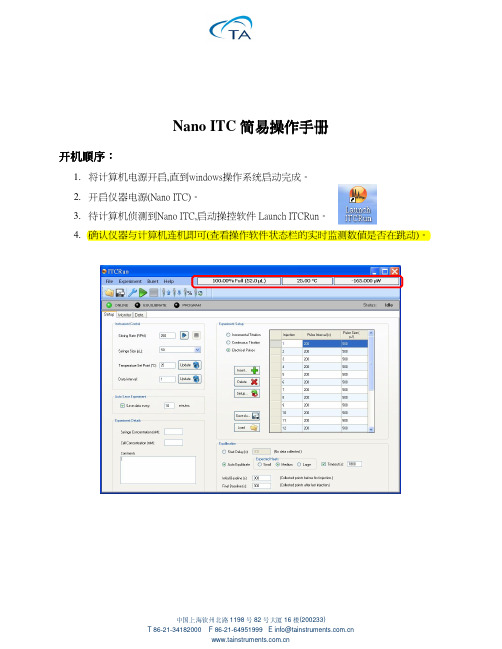
4. 确认仪器与计算机连机即可(查看操作软件状态栏的实时监测数值是否在跳动)。
中国上海钦州北路 1198 号 82 号大厦 16 楼(200233)T 86-21-34182000 F 86-21-64951999 E info@ 样品前处理: 样品前处理:1. 准备约50毫升的缓冲溶液(用来润洗样品池及注射器,或是实验结束时先用缓冲溶液 清洗)。
2. 将样品(滴定物及被滴定物)及缓冲溶液置入degassing station进行脱气。
3. 设定脱气温度(同操作温度)、真空度(400 mmHg以上)及脱气时间(10分钟以上)。
硬件操作( 硬件操作(样品装载) 样品装载):1. 样品池: a. 藉由上样针装载缓冲溶液(与样品相同的缓冲溶液)润洗样品池3-5次。
b. 移除样品池内缓冲溶液后,利用上样针取300 µL样品缓慢的注射至样品池内。
中国上海钦州北路 1198 号 82 号大厦 16 楼(200233)T 86-21-34182000 F 86-21-64951999 E info@ 2. 参比池: a. 以相同的方式用脱气候的去离子水润洗参比池。
b. 移除去离子水后,利用上样针取300 µL脱气的去离子水并缓慢的注射至参比池 内。
c. 再将参比插入参比池内。
3. 注射器: a. 仔细地装载滴定物至注射针筒中,并确认无任何气泡残留;若有可能,可将小气 泡(5-10 µL)固定在推杆前。
b. 将注射针筒以旋转的方式(依照注射针筒上的螺纹)装载在注射器上,将多余溢 出的样品擦拭干净。
c. 再将组合好的注射器及注射针筒安装在Nano ITC上。
Marvell NanoLab成员登录实验室手册说明书
Marvell NanoLab Member login Lab Manual Contents MercuryWeb Berkeley MicrolabChapter 1.10Miscellaneous EtchantsTable of ContentsAluminum Etchant►Type A(Transene Co., Inc.)►for VLSI►OthersAntimony EtchantAqua RegiaBismuth EtchantBrassCadmium►Sulfide Etchant(CdS)►Telluride(CdTe)Chromium EtchantChromium/Nichrome EtchantCobaltColumbiumCopperDislocation Etchants►Sirtl►Secco►Wright-Jenkins►ASTMGallium►Arsenide►PhosphideGermanium Etchant (and Germanium-Silicon)GoldIndium►Antimonide►Phosphide►Tin Oxide(ITO)Iron EtchantKovarLeadLuciteMagnesiumMagnesium FluorideMercuryMolybdenum(Moly)MonelNichromeNichrome EtchantNickel►Nickel Etchant►Nickel OxidesNiobiumP-EtchantPalladiumPicein WaxPiranhaPlatinumPolish – Fairchild’s “Magic Polish”Polysilicon Etchant(see also Silicon Etchant)Preferential Etch(see Dislocation Etchant Wright Jenkins Etchant)RhodiumRutheniumSilicon►Polycrystalline Silicon (Bell Labs)►Big Batch Silicon Etch(staff only)►Single-Crystal(Sensors)►EDP► F & K(Finne & Klein)►“B”(Bassous)►“F”(Fast)►“S”(Slow)►“M”(Medium)►KOH►TMAH►Dioxide Etchant(Buffered HF)►Silicon and Germanium Etchant►Silicon-Germanium (polycrystalline)►Monoxide Etchant►Nitride EtchantSilverStainless SteelTantalumTinTitaniumTitanium/TungstenTungstenTurpentineVanadiumWestinghouse Etchant(Si Polish Etch)ZincZnOZirconiumAluminum Etchant Type A (Transene Co., Inc.)►For VLSI aluminum etching, there is available a pre-mixed phosphoric/acetic acid mixture.Etch rate: ~ 100 Å/sec at 50ºC.►Corrosive. Avoid contact with eyes, skin and clothing. Avoid inhalation.Aluminum Etchant for VLSI►Etch rate ~ 2000 Å/min.16 parts phosphoric acid2 parts DI water1 part acetic acid1 part nitric acidAluminum Etchants - Others►These will not etch gold, etc.►Phosphoric acid at 60ºC►Sodium hydroxide (10% solution)►Trisodium phosphate at 190ºC►These will not etch ZnO. Etch rate ~ 100 Å/sec.►10 g K3Fe(CN)6► 1 g Potassium hydroxide (KOH) in 100 ml water at room temperature. Antimony Etchant►Etch (off of silicon) : HNO3H2O : HCl : HNO3 (1:1:1)H2O : HF : HNO3 (90:1:10)Aqua Regia►HCl : HNO3 (3:1)►Evaporation - removal:50% DI water45% HCl5% CuSO4► Dissolves gold.►Never store in a tightly sealed container!Bismuth Etchant► 5 ml Sulfuric acid5 ml Hydrogen peroxide90 ml DI waterNo heat necessary. Etches quickly.►H2O : HCl (10:1)Brass►Use brass dip (Turco) for etching and cleaning.► Ferric chloride (etch)►Ammonium persulfate: 20 g to 100 ml H2OCadmium Sulfide Etchant (CdS)►Dislocation pits on the (0001). Distinguishes between A and B faces.HNO3 : CH3COOH : H2O (6:6:1)Cadmium Telluride (CdTe)► Polishes10 ml HNO320 ml H2O4 g K2Cr2O7► Pits5% Br2 in methanol5 mg AgNO3Chromium Etchant►HCl : H2O2 (3:1) - This will also etch gold film.►HCl : H2O (1:1) - Heat to 50ºC, immerse substrate and touch with aluminum wire. Chromium/Nichrome Etchant►HCl : H2O2 (3:1) - This will also etch gold film.►HCl and touch with aluminum wire.Cobalt►H2O : HNO3 (1:1) ►HCl : H2O2 (3:1)Columbium►HF : HNO3 (1:1)Copper►Brass Dip, RT-2 Resist Stripper, FeCl solutions►H2O : HNO3 (1:5)►Oxide removal - cold solution of ammonium carbonate (slight etch)Dislocation Etchants►Sirtl Etchant1 part conc. HF or 50 g CrO3 in 100 ml H2O1 part CrO3 (5 M) 1:1 = HF : CrO3 solution500 g/L of solutionEtch rate ~ 3.5 µm/min. Good on {111}, poor on {100}, faceted pits.►Secco Etchant2 parts conc. HF1 part K2Cr2O7 (0.15 M)44 g/L of solutionEtch rate ~ 1.5 µm/min. Best with ultrasonic agitation. Good on all orientations. Non-crystallographic pits.►Wright-Jenkins Etchant2 parts conc. HF2 parts conc. acetic acid1 part conc. nitric acid1 part CrO3 (4M)400 g/L of solution2 part Cu(NO3)2 +3 H2O (0.14 M)33 g/L of solutionEtch rate ~ 1.7 µm/min. Ultrasonic agitation not required. Good on all orientations. Facetedpits, good shelf life.►ASTM Dislocation Etchant600 ml HF30 ml HNO30.2 ml Br228 g Cu(NO3)2 + 3 H2ODilute 1:10 with H2OGallium Arsenide► 1-2% Br2 in ethanolH2SO4 : H2O2 : H2O (5:1:1)Good polishing etches►Fused KOH at 300ºCGood crystallographic dislocation pits on the (100) surfaces► 1 ml HF2 ml H2O8 mg AgNO31 g CrO3Dislocation lines and striationsGallium Phosphide►Behaves similarly to GaAs and the above etches may be used.►HF : Acetic Acid : Saturated KMn2O4 sol'n (1:1:1)Good striations, free from pits on (110) surfacesGermanium Etchant (and Germanium-Silicon)►H2O2 (30%) at 90ºCEtch rates:100% Ge 4000 Å/min80% Ge 1000 Å/min60% Ge and less do not etch►H2O at 90ºCEtch rates:100% Ge ~ 200 Å/min< 60% Ge does not etch►RCA SC-1 (NH4OH : H2O2 : H2O) at 75ºCEtch rates:100% Ge ~ 4 um/min80% Ge ~ 9000 Å/min60% Ge ~ 500 Å/min40% Ge ~ 30 Å/min20% Ge ~ 10 Å/min0% Ge ~ 5 Å/minGold►Aqua Regia: HCl : HNO3 (3:1)►Saturated solution of KI in H2O, 1 iodine crystalIndium►Reacts with acids (HCl)►Slow etch (1000 Å/min.)HNO3 : H2O (1:1)Hot HCl : HNO3 (3:1)Indium Antimonide► HNO3 : HF : Acetic Acid (5:3:3)Polishes rapidly as it does most semiconductors, but bubble formation can ruin the polish.►0.2N solution of FeCl3 in HClDevelops pits.►HF : Acetic Acid : 2N HMnO4 (1:1:1)Good pit-free striations of (211) surfacesIndium Phosphide►Cut on diamond saw using slow feed. Lap using 5u powder. Degrease in acetone, then methanol. Chemical etch using 5% bromine by weight for about 2 minutes using a swirlingmotion. Rinse in methanol, DI water, N2 dry.Indium Tin Oxide (ITO)In order to etch ITO it is needed to reduce it to a metallic state. The reactions are:Zn + HCl = H2 + ZnCl2H2 reduces ITOSnO2 + H2 = Sn or SnOx with x smaller than 1Sn + HCl = H2 + SnCl4 which is soluble► The procedure:conc. HCl: H2O=1:1 at 50ºC.Add a small amount of Zn powder (on edge of a spatula). Put the wafer in the solution forabout 1 min. Watch for turbidity of the ITO. Transfer the wafer to another beaker containingconc. HCl (no dilution), for about 1 min.Take the wafer out and check if all the film was etched. Return to first solution if needed, at50 degrees.► HCl:HNO3 (3:1)Iron Etchant►H2SO4 : H2O (1:1)HCl : H2O (1:1)HNO3 : H2O (1:1)►To remove rust: saturated oxalic acid solution.Kovar► Cleaner:Ferric ammonium sulfate 50 gmlH2SO4 125mlHCl 150Heat to 60-80ºC► Electrolysis:HCl and salt, alternating voltage. Kovar or carbon electrode10% solution of HCl and a handful of saltLead►Acetic acid : H2O (1:1)►Lead deposited on glass can be removed with dilute HNO3.Lucite► Softens with acetone►Acetone : formaldehydeMagnesium► Hot H2O : NaOH (10:1 by weight)Follow with H2O: CrO3 (5:1 by weight)Magnesium Fluoride►Dissolves (sometimes) in hot commercial ferric chloride.Mercury►Dissolves and reacts in HNO3.►To clean (purify), bubble air through mercury, filter and vacuum distill.Molybdenum (Moly)►Hot concentrated H2SO4► Aqua Regia►HCl : H2O2 (1:1) (etches stainless steel)►Electrolysis 15 V ac moly or carbon electrode in pure H2SO4► Dissolves in H2O : HNO3 : H2SO4 (1:1:1) cold►45% formic acid : 45% H2O2 : 10% H2Heat 2 min at 80ºC.Monel►Clean with 50% HNO3 : salt. Wash with water, then dip in 50% solution HNO3, then rinse in water, then dip in ammonium hydroxide and dry.Nichrome►HCl : copper chloride (1:1)g► Ce(SO4)2 7.9mlWater 130Add:35 ml HNO3Nichrome Etchant (Transene Co., Inc.)►Contains nitric acid. Slightly irritating to skin. Wash area thoroughly if contacted.Nickel►HF : HNO3 (1:1)► Electrolysis:dc nickel electrode. H2SO4 or H3PO4. Reverse polarity several times, finish with nickel part aselectrode.Nickel Etchant (Transene Co., Inc.)►Contains nitric acid. Highly irritating to eyes, skin and mucous membranes, avoid inhalation of vapors.►Avoid contact with reducing agents.Nickel Oxides► HClNiobium► HF: HNO3 (1:1)P-Etchant (Phospho-Silicate Glass [PSG] Etchant)► 3 parts HF2 parts HNO360 parts DI waterPalladium►HC l : HNO3 (3:1) HotPicein Wax►Withstands all acids (including HF)►Thin/dissolve in trichloroethylene (TCE)Piranha►Excellent oxidant; removes most organic residues.5 parts H2SO41 part H2O2►Note: Always add peroxide to sulfuric acid, never vice versa! This is a self-heating solution.Platinum►Dissolves in Aqua RegiaHCl : HNO3 (3:1) 85°CPolish - Fairchild's "Magic Polish"► A - 2.5 g I2 in 1100 ml acetic acidB - HNO3 : HF (3:1)Add A to B (1:1) just prior to use.Polysilicon Etchant (See also Silicon Etchant)► 64% HNO3 / 33% H20 / 3% NH4F►189 ml HNO3 / 96 ml H20 / 7.5 ml NH4FPreferential Etch (See Dislocation Etchant Wright-Jenkins Etchant)Rhodium►HCl : HNO3 (3:1) HotRuthenium►HCl : HNO3 (3:1) HotSilicon Etchant - Polycrystalline Silicon (Bell Labs)This solution is mixed and bottled by Microlab staff. Bottles are stored in the tall white acid cabinet next to sink 432C (old lab).►Etch rate ~ 100 Å/sec33% DI water / 3% NH4F / 64% HNO3Bottle content:960 ml DI water75 ml NH4F (ammonium fluoride)1890 ml HNO3 (nitric acid)Big Batch Silicon Etch(staff only)Big batch slicon etch is used by staff to rework Tylan dummies in the heated bath, left side of sink7.48% DI water / 48% HNO3 / 2% HF at 50ºCSilicon Etchants - Single-Crystal (Sensors)►EDP Etchant for Single Crystal SiliconEDP etchant can be used on p-type wafers with <100> orientation, masked with either silicondioxide or silicon nitride. It leaves a cleaner, smoother silicon surface with partial etch thanKOH (see below). Heavy boron doping acts as an etch stop for EDP. Since EDP does notetch oxide, it is important to remember to dip off any native oxide from the silicon surfaces tobe etched in HF solution. Etch rates and temperatures are given below. Completeinstructions on the use of EDP are given in Chapter 1.3 of the lab manual.► Ethylenediamine N H2O(C H2)2N H2 1 mole = 50.10 gPyrocatechol C6H4(O H2) 1 mole = 109.1 gWater H2O 1 mole = 18.02g►F&K Etchant - Finne & Klein, Bell Labs at Murray Hill. J. Electrochem. Soc., Vol. 114, No. 9, September 1967, pp. 965-970Ethylenediamine 500 ml 35.1 mole%Pyrocatechol 88 g 3.7 mole%Water 234 ml 61.2 mole%Etch temp: 110ºCEtch Rate ratio: <100>:<110>:<111> 50:30:3Initial Etch Rate: 28 µm/hrOxygen Exposure: up to > 50 µm/hrÅ/hrMask Resistance: SiO2 200This is the earliest reported EDP (or EPW) composition. It is generally used in the temperature range 100-118ºC. At lower temperatures it develops insoluble residues. This composition, as well as other uncatalyzed EDP compositions, tends to 'age' rapidly with exposure to oxygen. The etch rate increases with time to 50 µm/hr and higher.The addition of pyrazine increases the <100> etch rate while making it less sensitive to oxygen expose. Pyrazine has a very small effect on the <111> etch rate so the <100>/<111> ratio increases with pyrazine content. The selectivity to boron content is reported by Reisman et al. to be similar for the F & K, B, and S etches. Also, the smoothness of the etching surface is improved by the addition of 0-6 g/L pyrazine. 8 g/> has shown some unevenness, <111> pyramids form, possibly due to the very high <100>/<111> etching ratio. IBM recommends 4 g of pyrazine to every liter of ethylene diamine for a smooth surface.►"B" Etchant - E. Bassous, IBM Research Center, Yorktown Heights, N.Y., U.S. Patent 3,921,916 (1975).Ethylenediamine 500 mlPyrocatechol 80 gWater 160 mlTemperature Range: 100-118ºCBoiling Point: 18ºC<100> Etch Rate (with pyrazine added):Pyrazine per 500 ml Ethylenediamine0 g 1.0 g 3.6 gat 100ºC 14 µm/hr 42 µm/hr 50 µm/hrat 115ºC 26 µm/hr 65 µm/hr 75 µm/hr► Mask Resistance:SiO2150 Å/hrSi3N4 80 Å/hrThis composition with or without pyrazine provides residue-free etching above 100ºC. ►"F" (Fast) Etchant - A. Reisman et al., IBM Research Center, Yorktown Heights, N.Y., J.Electrochemical Soc., Vol. 126, No. 8, August 1979, pp. 1406-1415.Ethylenediamine 500 mlPyrocatechol 160 gWater 160 mlTemperature Range: 100-118ºC<100> Etch Rate (with pyrazine added):Pyrazine per 500 ml Ethylenediamine0 g 1.0 g 3.0 gat 115ºC 27 µm/hr 68 µm/hr 81 µm/hr►"S" (Slow) Etchant - A. Reisman et al., IBM Research Center, Yorktown Heights, N.Y., J.Electrochemical Soc., Vol 126, No. 8, August 1979, pp. 1406-1415.Ethylenediamine 500 mlPyrocatechol 80 gWater 66 mlTemperature Range: 50-115ºC<100> Etch Rate (with pyrazine added):Pyrazine per 500 ml Ethylenediamine3.6 gat 50ºC 4.5 µm/hrat 75ºC 13 µm/hrat 95ºC 26 µm/hrat 105ºC 34 µm/hrat 115ºC 45 µm/hr►"M" (Medium) Etchant - Based on A. Reisman et al., as above.This etch is useful for etching below the boiling point in order to minimize agitation of the wafer. It etches at a rate between the "F" and "S" etches (hence "M" for medium). This etch prevents the formation of residues by the "F" etch by slowing oxidation of the surface through the reduction of the water content.Ethylenediamine 500 mlPyrocatechol 160 gWater 125 mlTemperature Range: 105ºC<100> Etch Rate (with pyrazine added):Pyrazine per 500 ml Ethylenediamine3.0 gat 115ºC 63 µm/hrOther references:K.E. Petersen, Proc. IEEE, vol. 70, No. 5, May 1982, pp. 420-457.K.E. Bean, IEEE Trans. ED-25, No. 10, October 1978, pp.1185-1193.N.F. Raley etal., J. Electrochemical Soc., vol. 131, No.1, January 1984, pp.161-171. ►KOH Etchant for Single Crystal SiliconKOH is a strongly anisotropic etch, preferring the <100> crystal plane. (The differential etch rate at 80ºC is on the order of 400:1.) Lines of rectangular areas to be etched must beparallel or perpendicular to the wafer flat. It is possible to etch around rectangular geometries,i.e., leave islands of silicon, if the proper convex corner compensation is used to preventrounding off of the corner due to undercutting along the <411> plane.750 g KOH : 1500 ml H2OTemperature: 80ºCEtch Rate: 1 µm/minute►TMAH Etchant for Single Crystal SiliconTMAH solution is commonly stocked in a 25 % concentration. Calculate the amount of 25% solution and DI water to make the desired etchant concentration (often 3%-15%). Under the hood, open TMAH container, add the desired amounts of solution to a DI water to bath, and heat to 80°C. Silicon nitride and silicon dioxide are both good masks for TMAH.Silicon Dioxide Etchant (Buffered HF)►NH : HF4 (6:1)Etch rate: ~1000 Å/min.Silicon and Germanium Etchant► CP-8 (fast) HNO3 : HF (5:3)CP-6 HNO3 : HF (5:1)CP-4 HNO3:HF : acetic acid (540 ml : 200 ml : 200 ml) Silicon-Germanium (polycrystalline)►H2O2 (30%) at 90ºCEtch rates:100% Ge 4000 Å/min80% Ge 1000 Å/min60% Ge and less do not etch►H2O at 90ºCEtch rates:100% Ge ~200 Å/min< 60% Ge doesn't etch►RCA SC-1 (NH4OH: H2O2: H2O) at 75ºCEtch rates:100% Ge ~ 4 um/min80% Ge ~ 9000 Å/min60% Ge ~ 500 Å/min40% Ge ~ 30 Å/min20% Ge ~ 10 Å/min0% Ge ~ 5 Å/minSilicon Monoxide Etchant►Saturated solution of NaOH►THIN FILMS OF SiO REACT EXPLOSIVELY WITH HF! Silicon Nitride Etchant►Hot phosphoric acid ~ 150ºCSilver► NH4OH: H2O2 (1:1)► Remove with HNO3►Clean with dilute HNO3 : NH4 (1:1)Stainless Steel► HF: HNO3►Aqua Regia (depends upon grade of stainless steel)► HCl►Electrolytic in diluted HClTantalum► HF: HNO3 : H2O (1:1:1)10 parts 30% KOH solution at 90ºC1 part 30% H2O2This mixture etches Ta2O5 and tantalum nitride at rates of 1000-2000 Å/min. Attacks photoresistsand must therefore be used with a metal mask (e.g. gold).Tin►HF : HNO3 (1:1)►HF : HCl (1:1)►Clean with ammonium chloride► Remove with HClTitanium►H2O : HF : HNO3 (50:1:1)►H2O : HF : H2O2 (20:1:1)►HF : H2O : ethylene glycol (20:10:220)No heating necessary. Rate ~ 1600 Å/min.►For evaporation, deposit Al before Ti to facilitate cleaning of glass cylinder.►Titanium dioxide is soluble in hot H2SO4.Titanium/Tungsten► Hydrogen peroxideTungsten►45% formic acid : 45% H2O2 : 10% H2OHeat 2 minutes at 80ºC.BleachHNO3 : HF (1:10-15). This will not etch gold.Boiling hydrogen peroxideFused NaOH (pellets, melted, 318ºC)► Electrolytic NaNO2HF: HNO3 (1:1)15 V ac with iron electrode (NaNO2 for polished finish)► CleaningBoil in 20% solution NaOH for 15 minutes of HNO3 : HF (1:1) for a few seconds.►Potassium ferricyanide-based etchK H2PO4 34.0gramsKOH 13.4 gramsgramsK3Fe(CN)6 33.0H2O ~1.0 literEtches tungsten without significantly attacking resist.Turpentine►Insoluble in water. Soluble in alcohol, chloroform, ether, acetic acid.Vanadium►H2 : HNO3 (1:1)► HF: HNO3 (1:1)Westinghouse Etchant (Si Polish Etch)►HF : acetic acid : HNO3 (3:5:15)Zinc► Reacts with HCl.ZnO►acetic acid : phosphoric acid : H2O (1:1:30)The etch rate is approximately 5000 Å/min. Zirconium►H2O:HF : HNO3 (50:1:1)►H2O:HF : H2O2 (20:1:1)See also:Dislocation Etches Secco EtchSilicon and Germanium Etchant, CP-4, 6 and 8 ►Ref.: J. Electrochem. Soc. 119. #7, 1972.。
Ipasolink设备安装手册资料

Modem1的中频电 缆接口
Modem2的中频电 缆接口
IDU接地
ODU1和2 的电源开关
保护 开关
USB接口
2对千兆光接口盘
室内单元IDU的介绍-3 Ipasolink400主面板
Modem1
Modem2
2M接口盘(可以安 装Modem盘,STM1A盘或其他板件
STM-1A盘,可以安 装Modem盘,2M接 口盘或其他板件
如果需要将默认V极化改为H时,先 将固定馈源的四个螺丝拧开,把馈 源顺时针或逆时针旋转90度,即为 H。天线极化必须与ODU极化相同
4.ODU与天线的组装-2
天线抱杆和ODU连接后的图像
对于6-8G的ODU需要软跳线和天线馈源连 接,ODU跟抱杆的固定需要托架固定件。
图片如下:
Ipasolink200最多支持2个1+0和1个1+1的配置.面板上可以看出有2个Modem盘是集成在主控板
上的。有16E1的接口盘,2个快速以太网口加2个千兆以太网口,2个千兆的光接口盘,
用中频电缆和ODU相连
告警和外接时钟接口盘 16对E1接口盘
风扇
中频电缆 接口
4个快速以太网或者2个 快速以太网和2个千兆以 太网口接口
以6-8G的 ODU为例
ODU的标签 。显示频率 和子带,序 列号,生产 日期等信息
接收电压 监控口
中频电 缆接口
ODU 接地
室外ODU单元介绍-2
6-8G ODU背面中频 电缆接口,需要用跳 线和天线馈源连接
6-8G ODU背 面电缆波导 接口
室外ODU单元介绍-3
11-38G ODU
显示设备为 15G的频率
IDU风扇
如果设备的风扇需要更换,请按照图示,将新的风扇 安装完成。如果设备在运行情况下,请快速更换,防 止设备原件因散热,造成损伤
5.瘦AP配置操作V1.1-W908v1.1

设置-2 带VLAN的SSID设置 的 设置
内部公开▲
3、在打开的绑定配置页面中选择SSID的网络接口,如左下图。 4、若在LAN2的绑定配置页面中没有要所需的SSID网络接口,则应 进入LAN1的绑定配置页面,将LAN1绑定的SSID接口删除。如 右下图所示:
<本文中的所有信息归中兴通讯股份有限公司所有,未经允许,不得外传>
AC发现方式 发现方式
内部公开▲
瘦AP上电后,可通过多种方式获得AC的IP地址,从而与AC建立连接。 发现方式:
DHCP Option 60 DHCP Option 43
• AP通过DHCP方式获得地址时,DHCP Server可以在Option 60或Option 43中携带 AC的IP地址。
广播
<本文中的所有信息归中兴通讯股份有限公司所有,未经允许,不得外传>
SNMP管理 管理-TRAP 管理
1.
内部公开▲
AP与网管建立连接后,点击工具栏上的小闹钟按钮。
<本文中的所有信息归中兴通讯股份有限公司所有,未经允许,不得外传>
SNMP管理 管理-TRAP 管理
2.
内部公开▲
进入trap控制窗口,此窗口会记录设备触发的所有 告警信息,如下图:
内部公开▲
在VAP配置页面,点击第一个“编辑”按钮设置管理 SSID。 在VAP页面点击其他“编辑”按钮,或“新建VAP”按钮, 进入VAP配置子页面,可进行数据SSID的参数设置和安 全配置。
<本文中的所有信息归中兴通讯股份有限公司所有,未经允许,不得外传>
设置-1 带VLAN的SSID设置 的 设置
创建DHCP连接 连接-2 创建 连接
FM8413-LC条码扫码引擎硬件使用手册说明书

FM8413-LC 条码扫码引擎硬件使用手册2019. 12本资料是为了让用户根据用途选择合适的上海复旦微电子集团股份有限公司(以下简称复旦微电子)的产品而提供的参考资料,不转让属于复旦微电子或者第三者所有的知识产权以及其他权利的许可。
在使用本资料所记载的信息最终做出有关信息和产品是否适用的判断前,请您务必将所有信息作为一个整体系统来进行评价。
采购方对于选择与使用本文描述的复旦微电子的产品和服务全权负责,复旦微电子不承担采购方选择与使用本文描述的产品和服务的责任。
除非以书面形式明确地认可,复旦微电子的产品不推荐、不授权、不担保用于包括军事、航空、航天、救生及生命维持系统在内的,由于失效或故障可能导致人身伤亡、严重的财产或环境损失的产品或系统中。
未经复旦微电子的许可,不得翻印或者复制全部或部分本资料的内容。
今后日常的产品更新会在适当的时候发布,恕不另行通知。
在购买本资料所记载的产品时,请预先向复旦微电子在当地的销售办事处确认最新信息,并请您通过各种方式关注复旦微电子公布的信息,包括复旦微电子的网站(/)。
如果您需要了解有关本资料所记载的信息或产品的详情,请与上海复旦微电子集团股份有限公司在当地的销售办事处联系。
商标上海复旦微电子集团股份有限公司的公司名称、徽标以及“复旦”徽标均为上海复旦微电子集团股份有限公司及其分公司在中国的商标或注册商标。
上海复旦微电子集团股份有限公司在中国发布,版权所有。
目录目录1产品综述 (4)1.1产品简介 (4)1.2产品特点 (4)1.3外观及结构 (4)1.4典型应用 (5)2使用注意事项 (6)2.1ESD防护 (6)2.2镜头防护 (6)2.3工作条件 (6)2.4散热 (6)3电气特性 (7)3.1工作电源要求 (7)3.2直流特性 (7)3.2语音特性 (7)4接口说明 (8)4.1FPC柔性软排线接口 (8)4.2线到板连接器 (9)4.3USB连接器 (9)4.4通讯接口 (10)4.4.1串口 (10)4.4.2 USB (10)4.5状态指示输出 (10)4.5.1蜂鸣器输出 (10)4.5.2指示灯输出 (10)4.6触发信号输入 (11)4.7语音输出接口 (11)版本信息 (12)上海复旦微电子集团股份有限公司销售及服务网点 (13)1产品综述1.1产品简介FM8413条码扫码引擎是复旦微提供的条码识读解决方案,用于识别常用的纸张以及手机屏幕显示的主流QR码,模组分为嵌入式模块和整机集成模块,嵌入式模块体积小巧,装配灵活,对外提供丰富的接口以满足用户的定制化需求,可满足大部分嵌入式设备的应用场景;集成模块结构更加完整,提供统一的接口,增强了设备的安全防护特性,用于对结构尺寸限制较少,快速应用的场景。
Mercury NanoSWITCH产品介绍说明书
Mercury Systems is a leading commercial provider of secure sensor and safety-critical processing subsystems. Optimized for customer and mission success, Mercury’s solutions power a wide variety of criticaldefense and intelligence programs.An IGMP snooping feature enables the network to operate at peak efficiency by limiting the IP multicast traffic to the ports that request it, while 802.1Q VLAN support quickly segregates network traffic. VLANs provide an additional layer of security by separating sensitive data from other network workgroups.Workload EfficiencyWith numerous Quality of Service (QoS) features, the NanoSWITCH ensures traffic is prioritized to deliver superior performance for real-time applications. These features include system management, voice, video, and bandwidth-intensive file uploads and downloads. Additional capabilities, such as IEEE 802.1p priority tagging, DSCP , and eight hardware traffic class queues maintain quality for real-time applications.Proven with VICTORYNanoSWITCH is the only field implemented VICTORY (Vehicular Integration for C4ISR/EW Interoperability) CTS compliant switch –a software configuration that provides a common data-bus centric approach which eliminates redundancy and reduces SWAP inArmy ground vehicles. The NanoSWITCH also meets multiple military standards including: MIL-STD-1275E, MIL-STD-704F, MIL-STD-461F,and MIL-STD-810G.D A T A S HE E Tw w w .t m s .m r c y .c o mACQUIRE ACQUIRE 100101010001101011110101100DIGITIZE ACQUIRE 100101010001101011110101100DIGITIZE PROCESS STORAGE EXPLOIT DISSEMINATEACQUIRE 100101010001101011110101100DIGITIZE PROCESS STORAGE EXPLOIT ACQUIRE 100101010001101011110101100DIGITIZE PROCESS ACQUIRE 100101010001101011110101100DIGITIZE PROCESS STORAGE The NanoSWITCH brings enterprise level layer 2/3 switching into harsh environments found in military ground, air and sea vehicles and offshore oil platforms.Reliable and CompactWeighing less than 3.6lbs, the Themis NanoSWITCH™ delivers multi-layer GigE Ethernet switch capabilities with an embedded x86 PC in a compact form-factor. Its multi-layer performance and cost-competitive pricing makes it an attractive choice for a multitude of field applications including:•Vehicle network switching •Distributed architecture vehicle controller•VICTORY compliant switch, router, timing, and control •WAN – LAN interconnectivity and firewall•Shared processing and peripheral communications Featuring sealed MIL connectors, the NanoSWITCH meets IP67 standards (water, dust, salt fog) and has an operating temperature range of -40°C to 71°C.Precision ControlThe NanoSWITCH’s 10x or 16x external GigE Ethernet ports operate at rates of 10, 100, and 1000 Mbps. It supports sophisticated IPv4 and IPv6 routing such as tunneling, IP Multicast, VLANs, IETF, IEEE, and DSL Forum standards. A full management suite and Command Line Interface (CLI) is included to simplify switch control and routing operations.•Vehicle Integration for C4ISR/EW Interoperability (VICTORY) implementedRugged Small Form-Factor 10/16 Port GigE Ethernet switchNanoSWITCH ™MIL Specification Compliance• MIL-STD-1275E - Ground vehicle power • MIL-STD-704F - Aircraft power (with no hold up)• MIL-STD-461F - EMC Army ground, Navy ground • MIL-STD-810G - EnvironmentalMIL-STD-810G Environmental Compliance• IP67 environmentally sealed (water, dust, salt fog)• Sealed MIL connectors • Altitude: 15,000ft • Immersion: 1m • Dust, salt, fog• Storage temperature: -50°C to 105°C • Operating temperature: -40ºC to 71ºC • Shock: 50g, 25ms half sine, all directions• Vibration: 5G RMS 8Hz to 2KHz, composite wheeled, cargo jet, helicopter profilesIEEE CmplianceE• 802.1D bridging and spanning tree • 802.1p QOS/COS • 802.1Q VLAN tagging • 802.1w rapid spanning tree • 802.1s spanning tree protocol • 802.1AB link layer discovery protocol • 802.3ad link aggregation with LACP • 802.3x flow control • 802.3ab 1000BASE-T • 802.3z GigE EthernetManagement MIBS• Fully MIB managed device • RFC 1213 - MIB-II • Ether-like MIB• SNMP-FRAMEWORK-MIB • RFC 1493 - BRIDGE-MIB • IF-MIB • RMON-MIBVetronics SBC PC• Embedded x86 SBC• AMD Fusion APU, 615MHz single core with Radeon HD 6250 GPU • 64KB L1, 512KB L2, 1GB DRAM • 64GB SSD• Trusted Platform Module (TPM)• External GB-GRAM/DAGR/Polaris compliant GPS Port with selectable RS232/RS422/RS485• 1x Internal GigE port into Switch (17th port) and 1x External GigE • VGA video output • 2x RS-232 ports • 2x USB 2.0 ports• Replaceable long-life RTC battery or external power • Linux Ubuntu installed as standardLayer 2/3 Feature Set• 16K L2 forwarding entries • 802.1w rapid spanning tree • 802.1s spanning tree protocol • 802.3ad link aggregation/LACP • 4-16 LAGs• 802.1Q VLANs (256-4K VLANs)• 802.1AB link layer discovery protocol • Port mirroring • Jumbo frames (10KB)• 802.3x PAUSE • Static MAC addresses • IGMPv1, 2, 3 snooping • MLDv1, 2 snoopingNetwork Management• 10/100/1000 management ports • RS-232 serial console port • Syslog • RADIUS • Tacacs • AAA• Simple Network Time Protocol (SNTP)• WEB management • File download via HTTP • SNMP v1/2/3Security Features• 802.1X Port-based Network Access Control (PNAC)• MD5 encryption• Port security-MAC-based filtering • Management access control • NAP full support • TPM for SBCQuality of Service (QOS)• Priority levels 8 hardware queues• Scheduling priority queuing and Weighted Round-Robin (WRR)• Shaping per port and per queue • Rate limiting for different packet types• Class of service:Port based, 802.1p VLAN priority or IPv4/v6 IP DSCPPower• 28V nominal isolated power input to MIL-STD-1275E • +/- 250V transient, 100V surge, 12V starting surge capable • Voltage ripple filtering • 34W maximum (22-31W Typical)•Status LED blanking control。
中兴 ZXR10 5009(V10)千兆接入交换机 说明书

ZXR10 5009(V1.0)千兆接入交换机用户手册中兴通讯股份有限公司ZXR10 5009(V1.0)千兆接入交换机用户手册资料版本 20060701-R1.0产品版本V1.0策划中兴通讯学院文档开发部编著胡鹏赵志强周继华审核虞成军* * * *中兴通讯股份有限公司地址:深圳市高新技术产业园科技南路中兴通讯大厦邮编:518057技术支持网站:客户支持中心热线:(0755)26770800 800-830-1118传真:(0755)26770801E-mail:doc@* * * *编号:sjzl20061267声明本资料著作权属中兴通讯股份有限公司所有。
未经著作权人书面许可,任何单位或个人不得以任何方式摘录、复制或翻译。
侵权必究。
和是中兴通讯股份有限公司的注册商标。
中兴通讯产品的名称和标志是中兴通讯的专有标志或注册商标。
在本手册中提及的其他产品或公司的名称可能是其各自所有者的商标或商名。
在未经中兴通讯或第三方商标或商名所有者事先书面同意的情况下,本手册不以任何方式授予阅读者任何使用本手册上出现的任何标记的许可或权利。
本产品符合关于环境保护和人身安全方面的设计要求,产品的存放、使用和弃置应遵照产品手册、相关合同或相关国法律、法规的要求进行。
由于产品和技术的不断更新、完善,本资料中的内容可能与实际产品不完全相符,敬请谅解。
如需查询产品的更新情况,请联系当地办事处。
若需了解最新的资料信息,请访问网站FAX :0755-********意见反馈表为提高中兴通讯用户资料的质量,更好地为您服务,希望您在百忙之中提出您的建议和意见,并请传真至:0755-********,或邮寄至:深圳市高新技术产业园科技南路中兴通讯大厦中兴通讯学院文档开发部收,邮编:518057,邮箱:doc@ 。
对于有价值的建议和意见,我们将给予奖励。
资料名称 ZXR10 5009(V1.0)千兆接入交换机用户手册产品版本 V1.0资料版本 20060701-R1.0 您单位安装该设备的时间为了能够及时与您联系,请填写以下有关您的信息姓名单位名称 邮编单位地址 电话E-mail好 较好 一般 较差 差 总体满意工作指导查阅方便 内容正确内容完整结构合理图表说明您对本资料的评价 通俗易懂详细说明 内容结构内容详细内容深度 表达简洁增加图形增加实例增加FAQ您对本资料的改进建议 其 他您对中兴通讯用户资料的其他建议前言手册说明本手册为《ZXR10 5009(V1.0)千兆接入交换机用户手册》,适用于ZXR10 5009千兆接入交换机。
嵌入式工业平板电脑PPC-TP17寸1037U外接电源 使用手册

版权声明随附本产品发行的文件为英曼达公司2013年版权所有,并保留相关权利。
针对本手册中相关产品的说明,英曼达公司保留随时变更的权利,恕不另行通知。
未经英曼达公司书面许可,本手册所有内容不得通过任何途径以任何形式复制、翻印、翻译或者传输。
本手册以提供正确、可靠的信息为出发点。
但是英曼达公司对于本手册的使用结果,或者因使用本手册而导致其它第三方的权益受损,概不负责。
认可声明Intel 和Pentium 为Intel Corporation 的商标。
Microsoft Windows®为Microsoft Corp. 的注册商标。
所有其它产品名或商标均为各自所属方的财产。
产品质量保证 (壹年)从购买之日起,英曼达为原购买商提供壹年的产品质量保证。
但对那些未经授权的维修人员维过的产品不予提供质量保证。
英曼达对于不正确的使用、灾难、错误安装产生的问题有免责权利。
如果英曼达产品出现故障,在质保期内我们提供免费维修或更换服务。
对于出保产品,我们将会酌情收取材料费、人工服务费用。
请联系相关销售人员了解详细情况。
如果您认为您购买的产品出现了故障,请遵循以下步骤:1. 收集您所遇到的问题信息(例如,CPU 主频、使用的英曼达产品及其它软件、硬件等)。
请注意屏幕上出现的任何不正常信息显示。
2. 打电话给您的供货商,描述故障问题。
请借助手册,产品和任何有帮助的信息。
3. 如果您的产品被诊断发生故障,请从您的供货商那里获得产品型号及配置。
这可以让我们尽快地进行故障产品售后。
PPC-TP17/C 用户手册第1页安全指示1. 请仔细阅读此安全操作说明。
2. 请妥善保存此用户手册供日后参考。
3. 用湿抹布清洗设备前,请从插座拔下电源线。
请不要使用液体或去污喷雾剂清洗设备。
4. 对于使用电源线的设备,设备周围必须有容易接触到的电源插座。
5. 请不要在潮湿环境中使用设备。
6. 请在安装前确保设备放置在可靠的平面上,意外跌落可能会导致设备损坏。
Un-link 最新AC控制器使用手册.

目录目录 .......................................................................................................................................... 2第一章详细配置指南简介 .....................................................................................................4 1.1本说明约定 .................................................................................................................4 1.2本说明章节安排 .........................................................................................................4第二章产品概述 ....................................................................................................................5 2.1 产品简介 .....................................................................................................................5 2.2 主要特性 .....................................................................................................................5第三章硬件描述 ....................................................................................................................6 3.1 面板布置 .....................................................................................................................6 3.2安装环境 .....................................................................................................................6第四章快速安装指南 .............................................................................................................7 4.1 硬件连接 .....................................................................................................................7 4.2 如何登陆 AC 控制器 ...................................................................................................7 4.3网络设置 .....................................................................................................................9 4.3.1子端口设置 ..............................................................................................................9 4.3.2瘦AP 端口设定 (10)4.3.3DHCP 配置 (10)4.3.4 链路检测 (11)4.4 RF配置 (12)4.4.1 AP默认配置 (12)4.4.2瘦 AP 配置模板 (13)4.4.3 瘦 AP 配置模板应用 (14)4.5 接入控制 (14)4.6 高级应用 (15)4.7 管理 (16)4.7.1 更改密码 (16)4.7.2 AC升级 (17)4.7.3 AP镜像上传 .........................................................................................................17 4.7.4 备份 /恢复设定 .....................................................................................................18 4.8 信息 ...........................................................................................................................19 4.8.1 AP资产管理 ..........................................................................................................19 4.8.2 瘦 AP 在线列表 ......................................................................................................19 4.8.3 无线终端列表 .. (21)第一章详细配置指南简介本文档旨在帮助您正确使用 AC 控制器的功能,内容包括 AC 控制器的性能特征以及所有功能的详细说明,若要使用路由器中的其他应用方面的功能,可以参考本文档相关部分内容。
NanoVNA 用户手册说明书
NanoVNAVector Network AnalyzerUser GuideWA5OKO 01/14/2020VNA’s provide very accu rate measurements because of their ability to be calibrated for a particular frequency range. This article was written to help amateur radio operators who are not familiar with the operation and calibration of the NanoVNA.Multifunction Switch PWR LED PWR SW BAT LED Type C USB Port.VNA BackMultifunction Switch – Pushing down on the switch brings up the touchscreen menu and rotating the switch will select the menu function.Power LED – This is a green that comes when the power switch is turned ON.Power Switch – Turns VNA ON and OFF. Note: The power LED stays ON for about 40 seconds it goes out. Battery LED – Blinks when charging and stops blinking went battery is charged. If the USB cable is plugged into a 5V power source, it charge even if the power switch is off.USB Port – This is a USB class “C” connector, which is bipolar, so if you order a longer cable, make sure it has the correct type of connector Trace SettingYou can have 4 traces running at the same time, using the touchscreen main menu, turn off all of the traces except Trace 0. Holding the key will turn the trace off.MA RKER RECA LL DISPLA Y CA L SCA LE CLOSETRA CE 2CHA NNEL STIMULUSFORMA T BA CKMA IN MENU TRA CE 1TRA CE TRA CE 3TRA CE 0BA CKS11 (CH0)S21 (CH1)Frequency SettingBefore performing the calibration procedure, the frequency range needs to be set. When you touch the Start key, the first screen will appear, then touch the bottom right hand corner of the numbers bar and the second screen will appear. I was measuring the 2M band, using the number pad, touch 144, M and x1 to set the Start frequency. Touch the Stop frequency key and enter 148 MHz Stop frequency, then touch Back key.Calibration ProcedureNow that you have entered frequency range, it’s time to calibrate the unit. Calibration is accomplished by applying an (OSLT) open, short and 50 ohm load to the CH0 (S11) connector, plus connecting jumper cable between the two VNA connectors for the THRU calibration. Using the touchscreen main menu:Using the calibration connectors from the calibration kit, install the Open connector on the Channel 0 (S11) connector and momentarily touch the Open menu key. Repeat this step with the Short and Load. If you are only going make S11 measurements, touch the Done key and save the calibration to one of the Save numbers and touch the Done key. If you are going to perform a S11 & S21 measurements, you must also perform the Thru calibration, install a jumper cable between the S11 & S21 ports and touch the Thru key. Touch the Done key, then select a Save number and touch the Done key. Note: You skipped the Isolation calibration. This requires that both connectors be terminated with a 50 ohm load and only one is supplied with the VNA. I’ve made many tests with and without performing Isolation calibration step and have seen no accuracy difference.MA RKER PA USE SWEEP CA L DISPLA Y CLOSERECA LL BA CKSPA N STA RT CW FREQ MA IN MENU STIMULUS STOP CENTER SHORT SA VE 2THRU DONESA VE 3ISOLA TION CA LIBRA TE DONE SA VE 1STIMULUSLOA D SA VE 0DISPLA Y RECA LL CLOSECA L BA CKCORRECT BA CKOPEN RESET MA RKER SA VE 4Measurement TypeThis VNA is a 2 port instrument, which is capable of making S11 and S21 measurrments. S11 is a reflective measurement, where the RF energy is transmitted into a device and reflected energy is compared to the forward energy. An antennas SWR measurement is a good example of a S11 measurement. Measuringinsertion loss of a length of coaxial cable is a example of S21 measurment, where the transmitted output level is compaired to the level received by the receiver. If you look at the VNA’s back cover, the S11 port is marked as TX and the S21 is idenified as a TX port.This Sample shows the SWR is 1.25:1Selecting Test ModeThe picture on the next page shows the insertion loss (S21) of a Helical Resonator Filter tuned for 146 MHz. Note that the measurement channel was changed from CH 0 to CH1.PHA SE CA L BA CKRECA LL FORMA T CLOSETRA CE BA CKDISPLA Y CHA NNEL MA RKER SCA LE SWR LOGMA G (S21)SMITH MA IN MENU DELA Y STIMULUSMOREThe Calibration Status is always shown on the left side of the display screen. C0: indicates that I’m using the 0 saved calibration table. D: Directivity. R: Reflection Tracking, S: Source Match. T:Transmission Tracking. X: for Isolation. In this case, I perform the Isolation calibration. You can store 5 calibration tables for each of the amateur frequency bands and use the Main Menu RECALL to select when calibration is needed. Note: If you see a C*, the calibration is missing.This picture shows that the filters Insertion Loss was 6.65 dB at 146 MHz’s.VNA Output LevelSTIMULUSREFLECT RECA LL BA CKCHA NNEL SCA LE TRA CE CH 1CH 0CA L THROUGH MA RKER DISPLA Y FORMA T BA CKMA IN MENU CLOSE(S21)SWR STIMULUSMA IN MENUSMITH CA L CHA NNEL DISPLA Y TRA CE PHA SE BA CKLOGMA G SCA LE DELA Y RECA LL MA RKER FORMA T CLOSEBA CKMOREA receiver input impedance can be difficult to measure. Most VNA’s output level is 0 dBm are more and could damage the receivers input stage. My MFJ-259B antenna analyzer output is 8 dBm. For repeater duplexers , the receiver’s impedance must match the duplexer’s 50 ohm impedance. I measured the NonoVNA’s sweep output level at 146 MHz’s and the level was -17.76 dBm. This is a safe level for any receiver, so the NanoVNA can be used to measure a receiver’s input (Z).Computer InterfaceI’m using a free software program developed by HexAndFlex, but there’s several programs on the web which I have not tried. https:///2019/09/15/getting-started-with-the-nanovna-part-3-pc-software/ You need to calibrate the VNA and set the frequency range before connecting the VNA to the computer. The computer will transfer this information to the program.The programs main screen picture is too small to read on this page size, so I will snip various sections of this screen for illustration purposes.When the program initially loads, you will need to select the “Connect to NanoVNA” box. My computer automatically connected to COM4 which was an open port. If the VNA doesn’t connect, select the “Rescan” box. When you finish using the program select the “Disconnect” box.Select the “Calibration” box and the screen below will appear.Notice that the “Active Calibration” source is the NanoVNA which was previously calibrated. If you a re going to use a different frequency range, you will need to create another calibration table. This program requires that you enter the Start and Stop frequencies and select the “Sweep” box each time you change VNA port termination during the SOLT calibration procedure. Save the calibration to your computer. You can save as many calibrations as needed and load the calibration needed for your particular test.Select the “Display Setting” box and screen below will appear.This screen allows you to choose how many display charts you desire and the type of measurement from the drop-down selection. In this case, I’ve chosen 4 charts and selected Impedance (Z), SWR, Return Loss and the Smith Chart. Note: I usually set the check the “Show Lines”, change the “Sweep Color” to Black and “Second Sweep” to White.The charts on the next page shows the test sweep results for the measurements I selected on the display setting. These tests show the test results of a 5/8 mobile antenna located on the roof of a car.The start and stop frequencies include the complete 2M band. Looking at the Impedance (Z) chart, the impedance varied between 62 and 45 ohms. The RED marker shows the (Z) was 59.2 ohms. GREEN marker was 50.2 ohms and BLUE marker was 44.41 ohms. I set the RED marker on the Return Loss chart to -15 dB. Most antenna design engineers try to obtain RL of -15 dB because that equals to an SWR of about 1.5:1.The marker data on the previous page also applies to these two charts. The Smith Chart used in this program does not include any line information and that’s ok if you are familiar with these charts. The following is a short lesson about Smith Charts.There’s only one horizonal line and it’s the resonant frequency line, where the trace crosses this line identifies the antennas resonant frequency. This line is also none as the pure resistance line, because at this point there’s no inductance or capacita nce in the ohms value. The circles represent resistance, but the ohms value above the horizonal line includes inductance and below capacitance is included. The chart on the next page shows the resistance value of each circle. The center circle is always 50 ohms.The curved segments of the Smith Chart represent reactance (X), which also measured in ohms. The reactance values above horizonal line are inductive and capacitive below the line. The chart below shows the reactive value of each segment.Look at programs S11 Smith Chart, the 5/8 mobile antenna is a non-resonance antenna, so the trace never crossed the horizonal resonant line. The trace is all above the horizonal line, so it is primarily inductive and any small value of capacitance that shows up in marker data is result of other measurements. The Green marker shows that trace crossed the 50-ohm circle at 146.88 MHz’s. If you like designing your on antennas, Smith Charts are a great tool!MarkersVNA AccuracyThe accuracy of VNA depends on things and I don’t expect a $45 instrument to be as accurate as a $20,000 VNA . There’s a simple test I use to determine just how accurate your VNA might be. Choose a frequency range that you want test. You can use this test to confirm that your calibration was successful.Test Procedure1.Calibrate the VNA using menu touchscreen.If the program does not transfer the frequency informationfrom the NanoVNA, you will need to manually type them in theStart and Stop boxes. There’s no way to signify if its Hz or MHz, so you must enter the complete number.Once you have selected a Marker and entered a frequency,you can use your mouse the move the Marker to any location.If You have more than one Marker on the screen, you mustselect the Marker you want to move2.Connect the NanoVNA to your computer and start the VNA program.3.Go to Calibration screen and make sure the program is using the VNA as the calibration source.4.From the Display Setting screen, choose only the Smith Chart measurement.5.Attach the 50 ohm load to the CH0 (TX) connector.6.Select the “Sweep” button on the program menu and allow it to complete the sweep.NanoVNA KC901SThe NanoVNA and KC901S are terminated with 50-ohm loads that are pure resistance, no inductive or capacitive char acteristics. Both VNA’s show the trace point to be on horizona l resistive line and on the 50-ohm circle.7.The 50-ohm load was removed and the connectors were shorted.Both VNA’s show that a short trace was on the 0-ohm circle, but the NanoVNA shows there is a small amount of capacitance. The same short was used when VNA’s were calibrated, so this error was caused by circuitry.8.The short was removed and connector were terminated with an open.Again, both traces are on the high resistance circle, but in this case, the NanoVNA showed to have a small amount of inductance.These tests were performed at a 2M frequency. I compared the NanoVNA to a high dollar VNA, and I’m surprised at how accurate this $45 VNA is.End of TestSummaryThis VNA is more accurate than a lot of instruments I’ve used. I replaced the 50-ohm calibration load that was included with the VNA I received, it measured 52.3 ohms. Checking a receivers input impedance can damage the receivers input stage if an antenna analyzer or VNA’s output is too high. The NanoVN’s output is only -17.7 dBm which is a safe level for this measurement. I have not used the computer program for very long and still learning some of its quirks. I’m using version 2.2. You need to use touchscreen stylus pin with a sharp point to navigate the menu on this VNA, especially if your fingers are large. I’ve included AE5CE Menu Structure Map is on the last page.。
NANO-1037U-1CIR 说明书 V1.1

N A N O-1037U-1C I R说明书V1.1-CAL-FENGHAI.-(YICAI)-Company One11037系列用户手册你现选用的产品型号为:NANO-1037U-1CIRRev:DATE :2014/07/112安全使用小常识1.在使用本产品前,请您务必仔细阅读产品说明书;2.对未准备安装的板卡,应将其保存在防静电保护袋中;3.在从防静电保护袋中拿出板卡前,应先将手置于接地金属物体上一会儿(比如10秒钟),以释放身体及手中的静电;4.在拿板卡时,需佩戴静电保护手套,并且应该养成只触及其边缘部分的习惯;5.为避免人体被电击或产品被损坏,在对板卡进行拔插或重新配置时,须先关断交流电源;6.在需对板卡或整机进行搬动前,须先关断交流电源;7.对整机产品,需增加或减少板卡时,务必先关断交流电源;8.当您需连接或拔除任何设备前,须先关断交流电源;为避免频繁开关机对产品造成不必要的损伤,关机后,应至少等待30秒后再开机。
液体渗入机器内机器暴露在潮湿的环境中机器工作不正常或用户不能通过本手册的指导使其正常工作机器跌落或受创机器有明显的破损迹象目录安全指导 (2)版权声明 (2)第一章主板简介及规格说明 (3)包装盒内物品清单 (3)主板规格表 (3)第二章硬件设备的安装说明 (4)安装前注意事项 (4)内存安装说明........................................................... (4)后置面板插座介绍 (4)主板插座及跳线的设定说明 (5)SATA 接口说明 (7)第三章BIOS简介及设定 ..... . (9)升级更新............................................................ ..9设定 (9)语言切换 (9)第四章驱动程序的安装..... .. (9)芯片组驱动程序安装 (9)板载显卡驱动程序安装 (9)板载网卡驱动程序安装 (10)板载声卡驱动程序安装 (10)驱动程序安装 (10)第一章主板简介及规格说明谢谢您采用了我司的NANO-1037U-1CIR系列主板,为了保证产品品质并适合市场需求,主板都通过了抗老化、低电压、各种温度、湿度环境下的反复测试均能满足行业的需求。
LCU-1S流动控制单元用户手册说明书

Set interval from 5 to 200 seconds
Duration XXX Sec
Set duration from 1 to 200 seconds
Timer Out 100%
Set timer output from 1 to 100%
Volume Out 100%
Set output volume from 1 to 100%
Product Overview
202 mm
Liquid Output XLR 3-Pin DMX Out / IN
4
95.8 mm
179 mm
LCD Control Panel Control Output Control Input Power Inlet Main Power Switch
Setup and Installation
▲ [UP]/[TIMER]
Up/Activate Timer function
▼ [DOWN]/[VOLUME] Down/Activate Volume function
[STOP]
Deactivate Timer/Volume function
{设备管理}诺西设备无线参数手册

{设备管理}诺西设备无线参数手册一、概述诺西设备是一款高性能的无线网络设备,提供稳定的无线信号覆盖以及强大的信号传输能力。
本手册将详细介绍诺西设备的无线参数设置方法,并帮助用户正确配置设备以获得最佳的无线信号质量和覆盖范围。
二、设备连接及登录1.请将诺西设备连接至电源,并将电源插头插入交流电源插座。
2.确保设备的网线正确连接至路由器或交换机等网络设备。
3.打开电脑,确保电脑与诺西设备连接至同一个局域网。
4.打开浏览器,输入诺西设备的默认IP地址(一般为192.168.1.1)并回车。
5. 在登录页面中输入默认用户名和密码(一般为admin/admin),点击登录进入设备管理界面。
三、无线参数设置1. 点击设备管理界面中的“Wireless”选项卡,进入无线参数设置页面。
2.在无线参数设置页面中,可以配置以下参数:- SSID(Service Set Identifier):网络名称,表示设备的无线网络名称。
- Channel(信道):选择无线信号的工作频段。
- Security Mode(安全模式):选择无线网络的安全加密方式。
- Encryption(加密方式):选择无线网络的加密算法。
- Key(密码):设置无线网络的密码。
- Transmit Power(发射功率):调整无线信号的发射功率。
3. 根据实际需求进行相应的参数配置,并点击“Apply”按钮保存配置。
四、无线信号优化1.选择适当的信道:为避免干扰,选择一个较少被其他无线网络使用的信道。
2.调整发射功率:根据实际需要,适当调整无线信号的发射功率。
3.定位设备:根据实际情况,将设备合理地放置在信号覆盖区域内,避免遮挡和干扰物。
4.定期更新固件:通过固件升级,可以获得设备的最新功能和性能优化。
五、无线安全设置1.使用强密码:设置安全的密码,包含字母、数字和特殊字符,长度不少于8位。
2.启用加密:选择适当的加密方式,如WPA2-PSK,以增加无线网络的安全性。
ZOTAC ZBOX NANO 产品说明书

with 2 screws.
3. Insert the hard disk /SSD into the socket and gently slide into
the connector.
3
4. Reinstall the screws of the hard disk bracket.
2 2
2 4
place by the arms of the memory slot.
INSTALLING A HARD DISK
1. Locate the hard disk bracket, remove the screw, and
1
remove the hard disk bracket.
2. Install the hard disk bracket to a 2.5-inch SATA hard disk /SSD
QUICK START GUIDE
PACKAGE CONTENTS
• 1 x ZOTAC ZBOX nano • 1 x ZOTAC VESA mount • 1ห้องสมุดไป่ตู้x AC adapter • 1 x Power cord • 1 x WiFi antenna • 1 x User Manual & Quick Start Guide • 1 x Support DVD
2
EN
FRONT PANEL
1. Power button 2. Power LED 3. SATA LED 4. WiFi LED 5. Memory card reader (SD/SDHC/SDXC) 6. Headphone/Audio Out jack 7. Microphone jack 8. USB 3.0 Type-C 9. USB 3.0 port
Vollrath 食材准备设备操作手册说明书
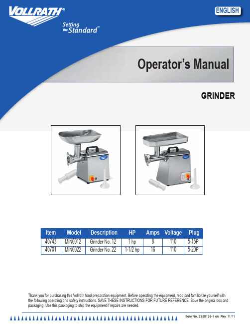
Item No. 2350138-1 en Rev 11/11EnglishOperator’s ManualGrinderThank you for purchasing this Vollrath food preparation equipment. Before operating the equipment, read and familiarize yourself with the following operating and safety instructions. SAVE THESE INSTRUCTIONS FOR FUTURE REFERENCE. Save the original box and packaging. Use this packaging to ship the equipment if repairs are needed.item Model description Amps Voltage Plug40743MIN0012Grinder No. 1281105-15P 40701MIN0022Grinder No. 221-1/2 hp 161105-20PO peratOr ’s M anual2F eatures and C ontrolsHAdBFGeCFigure 1. Features and Controls.TRAY. Funnels or flows the food product to the grinder chamber. THUMB SCREW. Holds the grinder chamber to the main body. MAIN BODY. Houses the motor, switch and other components. GRINDER CHAMBER. Grinds the food product and houses the worm gear, blade, grinder plate and coupling cover nut. COUPLING COVER NUT. Holds the grinder plate in place. CONTROL SWITCH. Switches the motor to “FORWARD”, “REVERSE” or “OFF”.RESET BUTTON. If the grinder becomes overloaded this button needsto be manually reset after allowing the unit to cool.FOOD PUSHER. Used to push the food product into the grinder chamber.o perationWArninGEntanglement hazard.Never place fingers, hands or other objects into the feed chute other than the food pusher provided with the appliance. Injury and product damage will occur.WArninGElectrical shock hazard.Keep water and other liquids from entering theinside of the equipment. Liquid inside the equipment could cause an electrical shock.s aFety p reCautionsTo ensure safe operation, read the following statements and understand their meaning. Please read carefully.WArninGWarning is used to indicate the presence of a hazard that can cause severe personal injury, death, or substantial property damage if the warning is ignored.CAUTiOnCaution is used to indicate the presence of a hazard that will or can cause minor personal injury or property damage if the caution is ignored.nOTENote is used to notify people of installation, operation, or maintenance information that is important but not hazard-related.For Your safety!These precautions should be followed at all times. Failure to follow these precautions could result in injury to yourself and others.To reduce risk of injury or damage to the equipment:Plug only into grounded electrical outlets matching the nameplate ratedvoltage.Do not operate unattended.Do not operate equipment in public areas and/or around children. Do not use an extension cord with this equipment. Do not plug thisequipment into a power strip or multi-outlet power cord.Check equipment before each use to insure the equipment is clean. Wear proper apparel. Do not wear loose fitting or hanging garments whileoperating this equipment.Use equipment in a flat, level position.Unplug equipment, turn off and let it cool before cleaning or moving. Do not spray controls or outside of equipment with liquids or cleaningagents.Do not clean the equipment with steel wool.Keep equipment and power cord away from open flames, electric burnersor excessive heat.Do not operate if equipment has been damaged or is malfunctioning inany way.F unCtion and p urposeThis unit is intended to be used to grind food products and meat for commercial foodservice operations only. It is not intended for household, industrial or laboratory use.Before using this equipment it must be cleaned and dried thoroughly. Clean all surfaces and parts before use.u npaCking the e quipment and i nitial s etupWhen no longer needed, dispose of all packaging and materials in an environmentally responsible manner.1. Remove all packing material and tape, as well as any protective plastic from the equipment.2. Clean any glue residue left over from the plastic or tape.3. Plug the equipment into a properly grounded electrical supply matching the nameplate rating. Damage to the equipment can occur if incorrect power is supplied to equipment.3EnglishO peratOr ’s M anual(D). Never use fingers, hands or other objects. Feed the food product and grind slowly at a rate that the grinder will accept. Do not force too much product into the grinder chamber. It can overload the grinder causing it to stop.8. When grinding session is over turn the control switch (F) to the “OFF” position. nOTe:if the unit becomes jammed or the discharge is erratic, turn the switch to the “OFF” position. Switch to the“reverse”position momentarily, turn the unit to the “OFF” position. Check the following:Thumb screw too tight; loosen and hand-tighten, do not over-tighten Discharge plate is blocked; remove and clear Blade edges are dull; have sharpened or replace Overloading and motor stops; switch too and reset. Blade is in backwards.C leaningTo maintain the appearance and increase the service life, clean your equipment daily.Grinder Chamber removal and disassembly1. Turn the control switch to the “OFF” position and unplug from its power source.2. Unscrew and remove the coupling cover nut (A) from the grinder chamber (B). See Figure 2.AB3. Remove the grinder plate (D) from the blade shaft (A). See Figure 3.ACBdFigure 3. grinder Plate, Cutout, locating Pin and Blade shaft 4. Carefully remove the knife blade (B) from the blade shaft (C). See Figure 4.CABFigure 4. Knife Blade and Blade shaft5. Remove the worm gear assembly (B) from the grinder chamber (C). See Figure 5.ACBdFigure 5. shaft Washer, Worm gear Assembly and grinder Chamber 6. Remove the shaft washer (A) from the worm gear shaft (B). See FigureO peratOr’s M anual 4Grinder Chamber Assembly and installation1. If necessary assemble the blade shaft (B) into the worm gear (A). SeeFigure 7.2. Slide the shaft washer (A) onto the worm gear shaft (B). See Figure 6.3. Slide the shaft washer (A) so that it is seated against the worm gearassembly (B) as shown. See Figure 5.4. Slide the worm gear assembly (B) and the shaft washer (A) into thegrinder chamber (C). Slide the worm gear shaft (D) in until it is seated fully.5. Slide the knife blade (B) so that the flat ground edges (A) face to theoutside as shown, onto the blade shaft (C). See Figure 8.CAdBFigure 8. Knife Blade and Blade shaft Figure6. Slide the knife blade (B) onto the blade shaft (C) so that it seatscompletely over the square (D). See Figure 4.7. Place the grinder plate (D) onto the blade shaft (A) so that the cutout(C) slides over the locating pin (B). See Figure 3.8. If a sausage filler is to be used, place it between the coupling cover(A) and the grinder chamber (B). See Figure 2.9. Thread the coupling cover (A) onto the grinder chamber (B) andtighten securely.6.ABFigure 6. shaft Washer and Worm gear shaft7. If desired remove the blade shaft assembly (B) from the worm gear (A). SeeFigure 7ABFigure 7. Blade shaft and Worm gearThoroughly clean and dry all parts.t roubleshootingProblem Possible Cause Course of ActionGrinder stops operating or output is erratic. Grinder is overloaded.Switch to the “Reverse”position momentarily, turn the unit to the “OFF” position. Check the following:Thumb screw too tight; loosen and hand-tighten, do not over-tighten Discharge plate is blocked; remove and clearBlade edges are dull; have sharpened or replacePress the reset button.Grinder stops operating or output is erratic. Blades are in backwards.Correct blade direction.Metal shavings or particles in food product.Blades are in backwards.Correct blade direction.Motor humms but does not ernor out of adjustment.Adjust governor per procedures posted at or contact Vollraths erviCe and r epairThere are no user serviceable parts within this appliance. To avoid serious injury or damage, never attempt to repair the equipment or replace a damaged power cord yourself. Do not send equipment directly to the Vollrath Company. Please contact the qualified professional repair service listed below.VOllrATh Technical service • 1-800-628-08325EnglishO peratOr ’s M anualV V U 6S R5U YXR E S E TB L AC KB L AC KL 1H o t W H I T EG R E E NL 2N e u t r a l E G r o u n d41G O V E R N O RM O T O R120 V o l t G r i n d e r I t e m # 4074330 m f d R u n C a p a c i t o releCtriCal draWing - g rinder ~ 40744VV U 6SR 5UYXR E S E TB L AC KB L AC K L 1H o t W H I T EG R E E NL 2N e u t r a l E G r o u n d41G O V E R N O RM O T O R200 m f d S t a r t C a p a c i t o r120 V o l t G r i n d e r I t e m # 4074430 m f d R u n C a p a c i t o rO peratOr ’s M anual6eXploded vieW draWing - g rinder ~ 407437EnglishO peratOr ’s M anualCallout Part number Description1XMIN1224FEEDER PAN 2XMIN2202MEAT PUSHER3XMIN1226BRASS BUSH FOR CHAMBER 4XMIN1204GRINDING CHAMBER HEAD 5XMIN1203COUPLING COVER NUT 6XMIN1207PLATE 1/8" 6XMIN1208PLATE 1/4" 6XMIN1209PLATE 1/2"740746GRINDER KNIFE (was XMIN1206)8XMIN1232WORM SHAFT FRONT 9N/A WORM10XMIN1231WORM SHAFT REAR8/9/10XMIN1205WORM (SPIRAL PROPELLER ASSEMBLY)11A XMIN1210GEARBOX COMPLETE (#11A,12,13,14,15,17,31,33,35,36,38,39,42,43)15XMIN1218BRASS WORM GEAR 16XMIN1222WORM DRIVE GEAR SPIRAL 18A XMIN1221MOTOR22XMIN1219PLASTIC BASE PLATE 23XMIN1212CAPACITOR, 200mfd 125V AC 24XAA0012CABLE RESTRAINT 27XMIN1213THUMBSCREW 28XMIX2004GOVERNOR PLATE 29XMIN1215GOVERNOR 30XMIN1216ON/OFF SWITCH 31XMIX3086BEARING, 6205Z 32XMIN1225RESET SWITCH 33XSLS6203BEARING, 620335XMIN2230OIL SEAL, 30 X 45 X 836N/A CIRCLIP A1537XMIN1217MEAT FUNNEL 39XMIN1230KEY, (6X6X15) 42N/A HEX BOLT 43XMIX2290FREEZE PLUG 45XMIN1220FEET48XAA0005POWERCORD, 120V, NEMA5-15P PLUG 49XMIN1229PLASTIC HANDLE 50XMIN1223GREASE TRAPPER BOLT 52XMIN1228HANDLE HEXBOLT 53XMIN1211SPACERO peratOr ’s M anual8eXploded vieW draWing - g rinder~ 407449EnglishO peratOr ’s M anualCalloutPart number Description1XMIN2223FEEDER PAN 2XMIN2202MEAT PUSHER 4XMIN2204GRINDING CHAMBER 5XMIN2203COUPLING COVER NUT 6XMIN2207PLATE 1/8" 6XMIN2208PLATE 1/4" 6XMIN2209PLATE 1/2" 7XMIN2206GRINDER KNIFE8/9/10XMIN2205WORM/ SPIRAL PROPELLER11A XMIN2210GEARBOX COMPLETE (#11A,12,13, 14,15,17,31,33,35,36,38,43)12XMIN2219FRONT HUB 15XMIN2220BRASS WORMGEAR 16XMIN2228WORM GEAR SPIRAL 18A XMIN2229MOTOR22XMIN2221PLASTIC BASE COVER23XMIN2212RUN CAPACITOR, 400mfd, 125V AC 24XAA0012CABLE RESTRAINT 27XMIN1213THUMBSCREW Not Shown XMIX4004GOVERNOR PLATE Not ShownXMIN1215GOVERNOR 30XMIN1216ON/OFF SWITCH 31XMIX3086BEARING, 6205Z 32XMIN2225RESET SWITCH 33XSLS6203BEARING, 620334N/A CIRCLIP, A1535XMIN2230GEARBOX OIL SEAL (TC30X45X8) ) 37XMIN2217MEAT FUNNEL 39XMIN1230KEY (6X6X15) 43XMIX2290FREEZE PLUG 45XMIN1220FEET48XAA0006POWERCORD, 220V, NEMA6-15P 49XMIN1229PLASTIC HANDLE 50XMIN1223GREASE TRAPPER BOLT 52XMIN1228HANDLE HEXBOLT 53XMIN1211SPACERO peratOr ’s M anual10W arranty s tatement For t he v ollrath C o . l.l.C.The Vollrath Company LLC warrants the products it manufactures and distributes against defects in materials and workmanship for a period of one year, except as specifically provided below. The warranty runs 12 months from the date of original installation. (End user receipt) 1. Refrigeration compressors – The warranty period is 5 years.2. Replacement parts – The warranty period is 90 days.3. Fry pans and coated cookware – The warranty period is 90 days4.EverTite™ Riveting System – The warranty covers loose rivets only, forever.5. Cayenne® Heat Strips – The warranty period is 1 year plus an additional 1 year period on heating element parts only.6. Ultra and Professional Induction Ranges – The warranty period is 2 years.7. Mirage and Commercial Induction ranges - The warranty period is 1 year.8. ServeWell® Induction Workstations – The warranty period is one year on the workstation table and 2 years on induction hobs.9. Slicers – The warranty period is 10 years on gears and 5 years on belts.10. Mixers – The warranty period is 2 years.11. Extended warranties are available at the time of sale.12. Vollrath – Redco products – The warranty period is 2 years.13. Optio / Arkadia product lines – The warranty period is 90 days.14. All non-stick products (i.e. fry pans and surfaces) are 90 days for the non stick surfaces.All products in the Jacob’s Pride ® collection, including the following, have a lifetime warranty:• NSF Certified One-Piece Dishers • NSF Certified Spoodle ® Utensils• NSF Certified Heavy-Duty Spoons with Ergonomic Handle• NSF Certified Heavy-Duty Basting Spoons • Heavy duty Turners with Ergonomic handle • One-Piece Tongs*• Heavy-Duty One-Piece Ladles*• Nylon Handle Whips • One-Piece Skimmers• Tribute ®, Intrigue ®, and Classic Select ® Cookware**Jacob’s Pride ® warranty does not cover Kool-Touch ®, non stick coatings and silicone handles.items sold having no warranty:• Meat Grinder Knives• Light Bulbs in Convection Ovens and Hot Food Merchandiser • Oven Door Seals • Oven Door Glass• Hot Food Merchandisers / Display Case Glass• Calibration and set up of gas equipment • Slicer / Dicer blades (table top food prep) – Redco and VollrathThis WArrAnTY is in liEU OF AnY OThEr WArrAnTiEs, EXPrEss Or iMPliED, inClUDing AnY iMPliED WArrAnTY OF MErChAnTABiliTY Or FiTnEss FOr A PArTiCUlAr PUrPOsEAs The Vollrath Company LLC’s only responsibility and the purchaser’s only remedy, for any breach of warranty, The Vollrath Company LLC will repair or, at its option, replace the defective product or part without charge, except as otherwise provided below:• For refrigeration compressors and the second year of the warranty on Cayenne® Heat Strips and mixers, The Vollrath Company LLC will provide the repaired or replacement part only; and the buyer will be responsible for all labor charges incurred in performing the repair or replacement.• To obtain warranty service, the buyer will be responsible to return to The Vollrath Company LLC any product (other than gas equipment that is permanently installed) weighing less than 110 lbs. or located outside of a 50-mile radius of a certified technician designated by The Vollrath Company LLC to perform warranty repairs. If a Vollrath Technician cannot be contacted check the website for service contact points. (Please refer to the Product Catalogue for weights and sizes of product)• No remedy will be available for products that have been damaged by accident, carelessness, improper installation, lack of proper setup or supervision when required, neglect, improper use, installation or operation contrary to installation and operating instructions or other causes not arising out of defects in materials or workmanship. At the buyer’s request, The Vollrath Company LLC will repair and or replace such products at a reasonable cost.• No remedy will be available for slicers where blade has not been sharpened (Refer to owner’s manual for sharpening instructions)• No remedy will be available for mixers damaged by changing gears while unit is running or overloading, in either case as determined by a Vollrath Certified Technician• Warranty work must be authorized in advance by The Vollrath Company LLC. See the operating and safety instructions for each product for detailed warranty claim procedures.• No remedy will be available for product returned and found to be acceptable to the product specification.• No remedy will be available under any warranty not registered as required below.liMiTATiOn OF liABiliTY:ThE VOllrATh COMPAnY llC shAll hAVE nO liABiliTY FOr inCiDEnTAl Or COnsEQUEnTiAl DAMAgEs OF AnY KinD, WhEThEr BAsED UPOn nEgligEnCE Or OThEr TOrT, BrEACh OF WArrAnTY, Or AnY OThEr ThEOrY.11EnglishO peratOr ’s M anual • All warranty claims will start with a call to Vollrath Technical Service support line.(800-628-0832).• A technical support professional will work to diagnose the issues, and provide the details for the service solution.• Name and phone number of person calling• Business name, street address, city, state and zip • Model and serial number• Date of purchase and proof of purchase (Receipt) •Name of dealer where unit was purchasedNOTE: Vollrath will not accept products sent without the proper procedure being followed.important:TO MAKE A CLAIM FOR ANY REMEDY UNDER THIS WARRANTY, YOU MUST REGISTER YOUR WARRANTY.r egister t odayONLINE: Register your warranty on-line now at NO WEB ACCESS: If you do not have access to the web, kindly register by completing the warranty registration form and faxing it to The Vollrath Co. LLC office in the country of purchase.The Vollrath Company, L.L.C. 1236 North 18th Street Technical Services: 800.628.0832 Service Fax: 920.459.5462。
NANO-1037U-1CIR 说明书 V1.1

1037系列用户手册Array你现选用的产品型号为:NANO-1037U-1CIRRev:1.1DATE :2014/07/11第1页安全使用小常识1.在使用本产品前,请您务必仔细阅读产品说明书;2.对未准备安装的板卡,应将其保存在防静电保护袋中;3.在从防静电保护袋中拿出板卡前,应先将手置于接地金属物体上一会儿(比如10秒钟),以释放身体及手中的静电;4.在拿板卡时,需佩戴静电保护手套,并且应该养成只触及其边缘部分的习惯;5.为避免人体被电击或产品被损坏,在对板卡进行拔插或重新配置时,须先关断交流电源;6.在需对板卡或整机进行搬动前,须先关断交流电源;7.对整机产品,需增加或减少板卡时,务必先关断交流电源;8.当您需连接或拔除任何设备前,须先关断交流电源;为避免频繁开关机对产品造成不必要的损伤,关机后,应至少等待30秒后再开机。
液体渗入机器内机器暴露在潮湿的环境中机器工作不正常或用户不能通过本手册的指导使其正常工作机器跌落或受创机器有明显的破损迹象目录安全指导 (2)版权声明 (2)第一章主板简介及规格说明 (3)1.1 包装盒内物品清单.......................................................3 1.2主板规格表 (3)第二章硬件设备的安装说明 (4)2.1安装前注意事项 (4)2.2内存安装说明........................................................... (4)2.3后置面板插座介绍 (4)2.4主板插座及跳线的设定说明 (5)2.5 SATA 接口说明 (7)第三章BIOS简介及设定 (9)3.1BIOS 升级更新............................................................ ..9 3.2BIOS设定 (9)3.3BIOS 语言切换 (9)第四章驱动程序的安装 (9)4.1芯片组驱动程序安装 (9)4.2板载显卡驱动程序安装 (9)4.3板载网卡驱动程序安装 (10)4.4板载声卡驱动程序安装 (10)4.5USB2.0驱动程序安装 (10)第一章主板简介及规格说明谢谢您采用了我司的NANO-1037U-1CIR系列主板,为了保证产品品质并适合市场需求,主板都通过了抗老化、低电压、各种温度、湿度环境下的反复测试均能满足行业的需求。
研江科技1037U工控机说明书

YJBOX1037UH一、简 介YJBOX1037UH 采用全铝合金结构,无风扇全封闭设计方案,整机超低功耗,外形紧凑,是一款应用于数字广告的小型全高清数字多媒体广告机。
它采用Intel NM70高速芯片组,搭配Intel 1037U 双核处理器,内建Intel®HD Graphics 显卡,支持1080P 视频播放,提供VGA 、HDMI 接口显示输出,VGA 与HDMI 同时使用时可实现独立双显示,借助结构紧凑而易于使用的网络设备,用户能够通过以太网来实现集中化控制、预定管理和多媒体内容的传输。
在接线基础设施不满足网络连通性的场所,可以选择使用 WLAN (WIFI 无线网卡)功能,为数字广告应用带来灵活性的最大化。
实 物 图● 外形紧凑、低噪音设计产品采用无风扇机身散热结构设计,机身为全铝合金外壳,外观尺寸小,可应用于各种狭小空间。
● 板载Intel 1037U 处理器板载低功耗、高性能Intel 1037U 处理器,功耗仅为 10W ,搭配 Intel NM70 高速芯片组构成嵌入式平台最佳的解决方案。
● 标配WIFI 无线网卡主机标配WIFI 无线网卡,在接线基础设施不满足网络连通性的场所,可以选择使用WLAN 。
后视图前视图二、接口指示图USB 1接口 COM6接口 Line_outMIC_IN USB 2接口 POWERUSB 5-6 天线 USB 3-4 HDMI VGA LAN Line_out MIC_IN DC12V_INCOM1COM2COM3COM4COM5三、硬件规格处理系统●CPU:板载 Intel 1037U处理器(双核1.86G),功耗仅为10W●芯片组:采用 Intel NM70 高速芯片组● BIOS:AMI 16MB Flash ROM●系统内存:1个204Pin DDRⅢSO-DIMM 插槽,支持1333/1066/800MHz的DDRⅢ内存最高可达4GB显示●显示芯片:Intel®HD Graphics显卡●显存大小:动态共享系统内存作为显存,最大可达到224MB●显示接口:VGA,HDMI● VGA:标准的DB15 接口(后面板),支持CRT 分辨率最高为2048x1536 ● HDMI:高清多媒体接口(后面板)支持分辨率最高为1920x1080● VGA+HDMI同时使用可实现独立双显示以太网●网络控制器:采用REALTEK 8111E 网络芯片●网络接口: 提供1个RJ_45接口(后面板)●速度:1000Mbps●支持网络唤醒(WOL)●支持WIFI 无线网卡及3G 模块存储●提供1 个2.5’硬盘位,可安装SATAⅡ规格硬盘●提供1 个Minisata插槽,可支持SSD硬盘AUDIO●芯片:采用ALC662 音频控制芯片,提供Line out和MIC IN●接口:提供2个Line out 插孔和2个MIC IN插孔(前/后面板)●特性:支持HD 6 声道高保真音频I/O● I/O 芯片:ITE 8782F-AX QFP-128P●串口:6 个标准的DB9 接口,支持RS232传输模式,支持+5V、+12V电压输出。
ITX-M19 VER 1.6主板说明书

- 1、下载文档前请自行甄别文档内容的完整性,平台不提供额外的编辑、内容补充、找答案等附加服务。
- 2、"仅部分预览"的文档,不可在线预览部分如存在完整性等问题,可反馈申请退款(可完整预览的文档不适用该条件!)。
- 3、如文档侵犯您的权益,请联系客服反馈,我们会尽快为您处理(人工客服工作时间:9:00-18:30)。
1037系列用户手册Array你现选用的产品型号为:NANO-1037U-1CIRRev:1.1DATE :2014/07/11第1页安全使用小常识1.在使用本产品前,请您务必仔细阅读产品说明书;2.对未准备安装的板卡,应将其保存在防静电保护袋中;3.在从防静电保护袋中拿出板卡前,应先将手置于接地金属物体上一会儿(比如10秒钟),以释放身体及手中的静电;4.在拿板卡时,需佩戴静电保护手套,并且应该养成只触及其边缘部分的习惯;5.为避免人体被电击或产品被损坏,在对板卡进行拔插或重新配置时,须先关断交流电源;6.在需对板卡或整机进行搬动前,须先关断交流电源;7.对整机产品,需增加或减少板卡时,务必先关断交流电源;8.当您需连接或拔除任何设备前,须先关断交流电源;为避免频繁开关机对产品造成不必要的损伤,关机后,应至少等待30秒后再开机。
液体渗入机器内机器暴露在潮湿的环境中机器工作不正常或用户不能通过本手册的指导使其正常工作机器跌落或受创机器有明显的破损迹象目录安全指导 (2)版权声明 (2)第一章主板简介及规格说明 (3)1.1 包装盒内物品清单.......................................................3 1.2主板规格表 (3)第二章硬件设备的安装说明 (4)2.1安装前注意事项 (4)2.2内存安装说明........................................................... (4)2.3后置面板插座介绍 (4)2.4主板插座及跳线的设定说明 (5)2.5 SATA 接口说明 (7)第三章BIOS简介及设定 (9)3.1BIOS 升级更新............................................................ ..9 3.2BIOS设定 (9)3.3BIOS 语言切换 (9)第四章驱动程序的安装 (9)4.1芯片组驱动程序安装 (9)4.2板载显卡驱动程序安装 (9)4.3板载网卡驱动程序安装 (10)4.4板载声卡驱动程序安装 (10)4.5USB2.0驱动程序安装 (10)第一章主板简介及规格说明谢谢您采用了我司的NANO-1037U-1CIR系列主板,为了保证产品品质并适合市场需求,主板都通过了抗老化、低电压、各种温度、湿度环境下的反复测试均能满足行业的需求。
是兼顾性价比、稳定、寿命长的高规格主流平台解决方案,同时为了兼顾大部份海内外市场,我们专门提供了中英文两种语言的BIOS。
本手册主要介绍了产品的规格参数及安装主板的步骤。
需要更加详细的主板BIOS设置信息可参看驱动光盘中的BIOS设置用户手册。
由于主板规格和BIOS软件将不断更新,本手册之相关内容变更恕不另行通知,一切仅供参考,请以实际为准或留意网上公布的升级版本.1.1 包装盒内物品清单v NANO-1037U-1CIR主板vSATA数据线第2页v 用户手册--选配v 驱动光盘v 质保卡v 合格证v 挡板*上述附带配件仅供参考, 实际配件请以实物为准,提示:如何识别报警声1、长鸣声为系统内存出错。
2、短“嘀”一声为开机声。
第二章硬件设备的安装说明2.1 安装前的注意事项:主板是由许多精密的集成电路及其他元件所构成,这些集成电路很容易因静电影响而损坏。
所以在安装前请先详细阅读此使用手册并做好下列准备:·安装前请勿任意撕毁主板上的序列号及代理商保修贴纸等,否则会影响到产品保修期限的认定标准。
·要安装或移除主板以及其他硬件设备之前请务必先闭电源,并且将电源线处插座中拔除。
·安装其他硬件设备至主板内的插座时,请确认接头和插座已紧密结合。
第3页·拿取主板时请尽量不要触碰金属接线部份以避免线路发生短路。
·拿取主板、中央处理器(CPU)或内存条时,最好戴上防静电手环。
若无防静电手环,请确保双手干燥,并先碰触金属物以消除静电。
·主板在末安装之前,请先置放在防静电垫或防静电袋内。
·当您要拔除主板电源插座上的插头时,请确认电源供应器是关闭的。
·在开启电源前请确定电源供应器的电压值是设定在所在窗口的电压标准值。
·在开启电源前请确定所有硬件设备的排线及电源线都已正确地连接。
·请勿让螺丝接触到主板上的线路或零件,避免造成主板损坏或故障。
·请确定没有遗留螺丝或金属制品在主板上或电脑机箱内。
·请勿将电脑主机放置在不平稳处。
·请勿将电脑主机放置在温度过高的环境中。
·在安装时若开启电源可能会造成主板、其他设备或您自己本身的伤害。
·如果您对执行安装不熟悉,或使用本产品发生任何技术性问题时,请咨询专业技术人员。
2.2 内存的安装:2.2.1 SUDIMM内存条的安装主机板支持DDRIII内存,容量可从最小的1333MB 扩展至最大8GB。
安装步骤如下:a. 将内存槽两端的白色卡榫向外扳开。
b. 将内存条有金手指的那边对准内存槽,注意内存条的凹孔要对应插槽的凸起点。
c. 将内存条插入插槽中。
若安装正确则插槽两端的白色卡榫会因为内存条置入而自动卡紧,否则不会卡紧。
2.1.2 SODIMM(笔记本)内存条的安装主机板支持DDRIII SODIMM内存,容量可从最小的1333MB扩展至最大8GB不等,具体安装步骤如下:a.将内存条的金手指以45度角度放入内存槽中b.然后稍微用力按下内存条至与内存槽卡扣平行位置,此时卡扣会自动卡紧内存条。
为了使系统稳定,请选用正牌内存。
2.3后置面板插座介绍1.电源接口DC:此插座为DC-12V电源连接端口。
2. HDMI 插座:HDMI(High-Definition Multimedia lnterface)是一种全数字化影像/声音传输介面,可以传播未经压缩的音频信号及影像信号。
此插座可兼容于HDCP规格并且支持Dolby TrueHD及DTS HD Master Audio 音频信号格式,最高可支持492KHz/24bit 8-channel LPCM音频输出。
您可以连接支持HDMI接头的显示器至此插座。
HDMI技术最高可支持至1920X1200的分辩率,实际所支持的分辩率会依您所使用的显示器而有不同。
3.显示接口:VGA此接口用来接显示器,是一种D型接口,上面共有15针空,分成三排,每排五个。
4.RJ45:接口类型为RJ45,支持RS-232标准定义:第4页第5页PIN1:RTS PIN2:DTR PIN3:SOUT PIN4:GND PIN5:GND PIN6:SIN PIN7:DSR PIN8:CTS5. USB (1-2)连接端口:此连接端口支持USB2.0/1.1规格。
您可以连接USB 设备到此连接端口。
例U 盘…等。
6. 音频输出:此插孔预设值为音频输出孔。
在使用耳机或2声道音频输出时,可以接至插孔来输出声音。
在4/5.1/7.1声道 声频输出模式中,可提供前置主声道音频输出。
2.4 插座及跳线介绍:1. VGA_H 接口:本主板提供1个1*12Pin VGA 插针接口(脚距:2.0mm ),管脚定义如下:第6页2.散热风扇电源插座SYS _FAN: 本板提供2个1*3Pin 风扇接口(脚距:2.54mm ),管脚定义如下:3. COM 接口:本板提供一个 2*5PIN 脚距=2.54MM 的COM 2接口,定义如下:4.CIR(红外接口):本板提供一个1*3PIN CIR (红外)接口,(脚距:2.54MM )管脚定义如下:5.SATA _PWR 接口 :本板提供1个1*4Pin (脚距:2.54mm ),的SATA_PWR 接口,管脚定义如下:6.清除跳线CLR_CMOS :本主板提供一个1*3PIN 的CLR_CMOS 接头,CLR_CMOS :CMOS 内容清除/保持设置(脚距:2.54 mm )CMOS 由板上钮扣电池供电。
清CMOS 会导致永久性消除以前系统配置并将其设为原始(工厂设置)系统设置。
其步骤:(1)关闭计算机,断开电源;(2)瞬间短接JCC1插针;(3)开计算机;(4)启动时按屏幕提示按键进入BIOS 设置,重新加载最优缺省值;(5)保存并退出设置。
定义如下 :SYS_FAN7.前面板接口 F_PANEL:本板提供1个2*5PinF-PANEL接口(脚距:2.54mm),电脑机箱的电源开关、复位开关硬盘指示灯及电源指示灯可以接此接脚8. F-USB接口(USB2.0连接端口扩展插座):本主板提供1个 2*5pin插针形式USB接口(脚距:2.54mm)。
定义如下:9. 前置音频接口 F_AUDIO:本主板提供一个2*5PIN F-AUDIO脚距:2.54MM 的前置音频接口,定义如下:10.麦克输出(IN_MIC):本板提供一个1*2PIN麦克输出(IN_MIC)插针,(间距:2.0MM)管脚定义如下:2.4.10BAT(电池)此电池提供电脑系统于关闭电源后仍能记忆CMOS资料(例如:日期及BIOS设定)所需的电力,当此电池的电力不足时,会造成会造成CMOS的资料错误或遗失因此当电池电力不足时必须更换。
您也11可以利用拔除电池来清除CMOS资料:1.请先关闭电脑,并拔除电源线。
2.小心地将电池从电池座中取出,等候约一分钟。
(或是使用如螺丝起子之类的金属物碰触电池座的正负极,造成其短路约五秒钟)3.再将电池装回。
4.接上电源线并重新开机。
注:·更换电池前,请务必关闭电脑的电源并拔除电源线。
·更换电池时请更换相同型号的电池,不正确的型号可能引起爆炸的危险。
·若无法自行更换电池或不正确定电池型号时,请联络购买店家或代理商。
·更换下来的旧电池须依当地法规处理。
第7页接口说明(接口描写说明:需描写接口数量+接口方式+脚距+特殊说明/注意事项(根据实际情况写);此部分标准管脚定义可由逻辑工程师提供,也可由说明书制作员提供逻辑工程师确认,其他相关描述及注意事项由逻辑工程师提供SATA接口:本主板提供1个SATA接口和,定义如下:SATA硬盘热插拔SATA硬盘热插拔需注意:(1)硬盘必须支持:SATA 2.0接口,并且采用15芯SATA硬盘电源接口。
(2)芯片组驱动程序支持SATA硬盘的热插拔。
(3)不能对操作系统所在的SATA硬盘进行带电热插拔。
请按照如下步骤进行SATA硬盘热插拔,否则,操作不当会导致硬盘损坏和数据丢失。
热插入SATA硬盘步骤:步骤1:请将SATA电源线1x4-针脚(白色)一端接到电源适配器的1x4-针脚电源线一端。
