RecurDyn Centrifuge Simulation 仿真教程
RecurDyn中文实例教程_T01_叶献孟
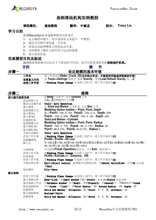
选择Object Control ,将Slide向+X方向移动300mm.完成后保存。
步骤三
创建旋转链接 创建球铰
创建平移
定义运动
创建连接
Joint->Revolute,选择Point,Direction模式,输入Point1(-70,0,170),Point2(-20,0,170) Joint->Shperical,选择Body,Body,Point模式,选择曲柄和连杆,输入Point(60,0,30);Joint->Shperical,选择连杆和滑块,输入Point(290,0,50)
选择Point,Point,Radius,输入Point1 :10,0,170;Point2 :30,0,170;Radius: 20.右 击选择Exit 选择Object Control ,将Link1向-X方向移动70mm 右击Crank,选择Propeties ,选择Graphic Property .将颜色设置为灰色,点击OK File->Save
创建圆柱体
改变圆柱体名称 编辑连杆 创建球体 联合杆和球体
选择Point,Point,Radius输入模式,输入Point1 :-60,0,30; Point2 :290,0,50;Radius :7 在Database window ,右击Cylinder ,选择Property ,在General 中,将Body1改为 Connecting_Rod 在Database window ,右击Connecting_Rod ,选择Edit, 在Solid and Marker->Ellipsoid ,输入Point:-60,0,30;Distance :13.第二球体: Point:290,0,50;Distance :13 Boolean->Unite ,先后将两个球体和圆柱体链接起来。并退出(右击,Exit)
欧倍尔增强复合材料虚拟仿真实验说明书
不饱和聚酯树脂的合成及玻璃纤维增强复合材料虚拟仿真实验说明书北京欧倍尔软件技术开发有限公司2018年6月地址:北京市海淀区清河永泰园甲1号建金商厦420-423室 邮编:100193目 录第一章 软件简介 (1)1.1 概述 .................................................................................................................................... 1 1.2 软件特色 ............................................................................................................................ 1 第二章 软件安装 ............................................................................................................................. 2 第三章 软件操作说明 (2)3.1 软件启动 ............................................................................................................................ 2 3.2功能介绍 ............................................................................................................................. 3 3.3界面介绍 .. (4)3.3.1菜单功能条 ............................................................................................................ 4 3.3.2仓库功能条 ............................................................................................................ 5 3.3.3操作指导栏 ............................................................................................................ 5 3.3.4评分界面 ................................................................................................................ 6 3.4 实验操作 . (6)3.4.1实验准备及装置搭建 ............................................................................................ 6 3.4.2不饱和聚酯树脂的合成 ........................................................................................ 9 3.4.3加固化剂配料 ...................................................................................................... 10 3.4.4玻纤增强复合材料的制备 . (11)第四章 注意事项 (13)4.1 软件运行注意事项及常见问题 (13)4.1.1 软件运行注意事项 ............................................................................................. 13 4.1.2 其中容易被杀毒软件阻止的程序 ..................................................................... 14 4.2安装过程中常见问题 . (15)4.2.1 控件注册失败 (15)第一章软件简介1.1 概述本软件是基础化学学科教育信息化建设项目,旨在为本科院校化工相关专业的学生提供一个三维的、高仿真度的、高交互操作的、全程参与式的、可提供实时信息反馈与操作指导的、虚拟的基础化学模拟操作平台,使学生通过在本平台上的操作练习,进一步熟悉专业基础知识、了解化学实验室实际实验环境、培训基本动手能力,为进行实际实验奠定良好基础。
基于RecurDyn的机电一体化仿真
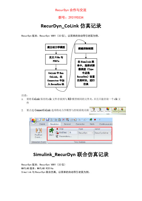
RecurDyn_CoLink仿真记录RecurDyn版本:RecurDyn V8R1(32位),以简单的自动导引老鼠为例。
注意:1.需将CoLink保存的.clk文件存放到与RD模型相同的文件夹,并且只能存放一个.clk文件2.要点选ConnectCoLink选项将动力学模型与控制系统关联Simulink_RecurDyn联合仿真记录RecurDyn版本:RecurDyn V8R1(32位)MATLAB版本:MATLAB R2014aSimulink与RecurDyn联合仿真,以简单的自动导引老鼠为例。
RecurDyn合作与交流群号:293195534采用1.0的接口在MATLAB中产生报错:采用2.0的接口未发生报错。
注意:3.需将MATLAB工作路径设置为存放RD模型与导出关联的.M文件的文件夹4.联合仿真时需将RD模型关闭,否则无法仿真5.仿真时RD模型演示一次后自动关闭步骤:1.建立多体动力学模型,保证其正常工作,保存到当前路径2.建立动力学模型输入变量PINs与输出变量POUTs3.建立RecurDyn与MATLAB关联的.M文件,export到当前路径,如图4.启动MA TLAB,将MA TLAB工作路径设置为存放RD模型与导出关联的.M文件的文件夹,即当前路径5.Run关联.M,工作区显示相关信息6.命令窗口输入rdlib或makerd,弹出包含RD的Plant Block的Simulink model,在里面搭建控制框图,保存在当前路径,注意:保存格式必须是.mdl而不是.slx,否则后期无法读取文件,最后关闭MATLAB程序即可7.如图依次进行:设置MATLAB的安装目录,一般是…bin\win32\MATLAB.exe或…bin \MA TLAB.exe 导出run Simulink Model的.M文件到当前路径,注意名字不要与关联.M文件名字一致Simulink Model选择第6步导出的.mdl文件,OK退出8.切换到模型Analysis界面,进行Dyn/Kin仿真,将看到MA TLAB启动,运行,关闭,同时模型进行动画演示9.切换到Plot模块进行绘图37RecurDyn_CoLink_Simulink联合仿真记录RecurDyn版本:RecurDyn V8R1(32位),以简单的自动导引老鼠为例。
RecurDyn跌落仿真中的应用
1. 2. 3. 4.
Page 12
创建地面
地面RecurDyn定义为刚体,创建步骤: 点击Professional选项创建Box Box的创建方式为Point,Point ,输入坐标点(-650,-1100,-500) (750,-1110,900),如图所示 双击刚创建的Box,进入Body编辑模式 在Geometry栏中的Surface选项中点击 Face Surface,选择Box的上表面鼠标点击 创建Face Surface。 “Exit”退出Body编辑模式
随着CAE技术的逐渐成熟,跌落仿真分析,现在越来越多的企业及学校利用 CAE软件对各种各样的产品进行设计创新及改良。把科学和实践相结合为国家 的明天创造价值。
本次跌落仿真选取新一代多体动力学仿真软件RecurDyn作为工具, 定义茶杯作为本次跌落的仿真对象,选择玻璃和钢两种材料分别进行 跌落仿真分析。
Page 10
修改单元属性,选择需要输出信息的节点
1. 双击生成的柔性体模型,进入柔性体编辑模式。 2. 点击软件上方的 图标,在弹出的对话框中查看单元属性。 3. 查看网格模型,点击上栏的OutPut 选项点击Add/Remove添加需要输出的 节点信息的节点“OK”(本模型选取了 3个节点作为应力采集点,如下图)
Page 16
后处理
仿真完成,点击Analysis栏中的Plot,进入后处理模块观察仿真结果。
工具选项中可 以将仿真动画 导入后处理窗 口,动画与曲 线可实时显示
多窗口显示
结果数据选择
Page 17
查看后处理结果
节点12290的速度曲线
Page 18
查看后处理结果
节点12290的节点位移曲线
Page 19
RecurDyn电钜运动分析仿真
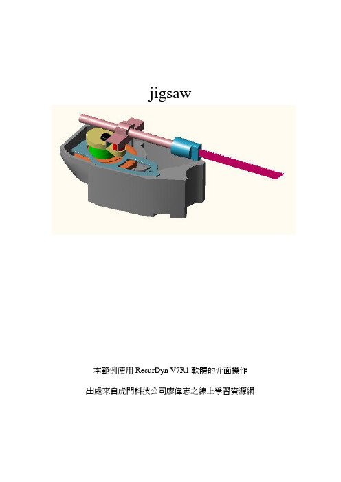
jigsaw本範例使用RecurDyn V7R1軟體的介面操作出處來自虎門科技公司廖偉志之線上學習資源網¾Part 1¾操作介面認識¾「merge」工具使用¾將多個單一零件,合併成單一零件¾旋轉 / 平移 / 固定接頭¾運動函數撰寫¾ Part 2¾複製接觸力所需接觸曲面¾進入「Body Edit Mode」編輯¾曲面接觸力定義¾Ext. Surface to Surface contact force ¾Part 3¾求解( Eigenvalue / Kinematic / Dynamic) ¾線性化分析¾動力學分析Part 11. 輸入模型名稱,中間不要有空格,第一字需要是英文字。
「中文命名不建議使用」輸入完後按OK( Parasolid , IGES , STEP , SAT , STL , etc2. 引入外部CAD檔案3.點選Icon Size ,改變Icon & Marker 大小後,按OK4. 點選上方功能表Tools → Merge Body,點選如圖的資料後按空白鍵取消打勾(有打勾,表示要合併的物體,所以要將沒有要合併之物體打勾取消)「Merge Body」可以將數個零件合併成單一零件,但使用上要注意合併後之質心位置和慣性特性是否與合併前相同,若有明顯差異則需要以人工方式填入正確的質量和慣性矩資料!!5. 接著點選B,點選要合併在該物體上3.出現該物體名稱1.2.6. 點選上方功能表Tools → Merge Body ,點選如圖的資料後按空白鍵(留下三個打勾之合併物體)7. 接著點選B ,點選要合併在該物體上3.出現該物體名稱1.2.8. 除了Ground 外,共有四個物件9. 點選視窗,View at Front10. 點選Joint → Translational 平移接頭(只有軸向一個單自由度)定義物體之間的拘束關係--「JOINT」依不同運動自由度,RECUDYN提供豐富的選擇定義彼此之間的關係,接頭也有人稱作「運動副」,但基於英文原意JOINT,簡稱「接頭」。
基于Matlab与RecurDyn的电传动履带车辆的联合仿真
修稿日期:2007-06-20作者简介:赵玉慧(1981-),女,硕士研究生.臧克茂(1932-),男,教授,研究生导师.文章编号:1009-4687(2007)03-0024-04基于M a tl ab 与Recur D yn 的电传动履带车辆的联合仿真赵玉慧, 刘春光, 臧克茂(装甲兵工程学院控制系,北京 100072)摘 要:为了建立精确的履带车辆动力学模型,实现电传动控制系统负载的动态加载,以某型履带车辆为例,分别建立了基于Matlab 的控制系统模型和基于Recur Dyn 的动力学系统模型,通过Matlab 和Recur Dyn 间的接口技术对其进行联合仿真,为履带车辆电传动系统仿真提供了新的手段,为制定比较精确的整车控制策略提供了有效的技术支持.关键词:电传动;联合仿真;Recur Dyn中图分类号:U46916+94 TP39119 文献标识码:ACo -si m ul ati on of the Electr i c Dr i ved Ar mored Vehi cle Based on Matl ab and Recur DynZHAO Yu 2hui, L I U Chun 2guang, Z ANG Ke 2mao(Depart m ent of contr olling engineering of the Acade my of A r mored Force Engineering,Beijing 100072,China )Abstract:A contr ol syste m and a dyna m ic syste m of s o me tracked vehicle are modelled based on Matlab and Recur Dyn res pectively,and the t w o models are co -si m ulated with the Recur Dyn /contr ol interface t o establish an exact dyna m ic syste m model,and l oad the contr ol syste m dyna m icly .Si m ultaneously,it p r ovides a ne w method f or the si m ulati on of the tracked vehicle electric syste m and a more effective tech 2nique support for establishing a p recise contr ol strategy .Key words:electric drive;co -si m ulati on;Recur Dyn 在现有的电传动系统仿真研究中,驱动电机负载力矩通常根据车辆行驶理论数学模型计算得到1该方法建立的车辆动力学模型精度不高,且无法实现车辆电传动控制系统负载的动态加载1多体动力学仿真软件Recur Dyn 的Track /H M 模块为解决履带车辆运动学、动力学建模提供了新的手段1本文分别采用Matlab 和Recur Dyn 建立电传动系统的控制模型和动力学模型,采用Matlab 和Recur Dyn 间的接口技术实现了负载的动态加载,从而完成了电传动车辆的联合仿真11 电驱动系统控制模型与其它电动机相比,永磁同步电动机具有可靠性好、效率和功率密度高的优点,因此在该控制系统中采用永磁同步电动机作为其驱动电机,控制方2007年第3期车辆与动力技术Vehicle &Power Technol ogy总第107期法采用最常见的矢量控制技术[1]1111 电动机数学模型分析正弦波电流控制的调速永磁同步电动机最常用的方法是dq轴数学模型1忽略电动机铁心的饱和,不计电动机中涡流和磁滞损耗且认为电动机电流为对称的三相正弦波电流1则其电磁关系可表示为[1]:u d=R i d+pψd-ωψqu q=R i q+pψq+ωψd,(1)ψd=L d i d+ψfψq =L q i q.(2)其中 Lq,L d为电机q轴、d轴电感;R为电机定子绕组电阻;iq,i d为电机q轴、d轴电流;u q, u d为电机q轴,d轴电压;ω为电机转子角速度; p为电机磁极对数1机械运动方程为:dω/d t=J(T e-T m)/p.(3)其中 J为电机转动贯量;f为电机转动摩擦系数; T m为负载转矩;T e为电机电磁力矩1112 矢量控制矢量控制实际上是对电动机定子电流矢量相位和幅值的控制1由式(1)、(2)知,电动机的力矩取决于定子电流的空间矢量is,而i s的大小和相位又取决于is 和iq,即控制i d和i q便可控制电动机的力矩1通过这两个电流的控制,使实际id 和iq跟踪指令值i3d 和i3q,从而实现电动机力矩和转速的控制1为了充分发挥电机低速时的最大力矩,当控制系统处于恒力矩调速区时采用最大力矩/电流控制,为了使电动机能恒功率运行于更高的转速,当控制系统调速范围处于恒功率调速区时采用弱磁控制1113 电传动控制系统电传动系统控制简图如图1所示:ω和θ为检测出的电动机转速和角速度空间位移1检测到的转速与指令值比较后的偏差作为速度控制器的输入1速度控制器的输出即为力矩的指令值,力矩指令值作为力矩控制器的输入,根据前述的控制策略计算定子电流分量i3d 和i3q,经过矢量逆变换后即可得到电动机三相电流的指令值,采用滞环P WM电流控制实现流跟踪,从而实现电动机的控制1图1 永磁同步电动机传动系统简图2 负载模型为了提高该控制系统动力学模型的精度,系统使用Recur Dyn软件对整车行动部分多体动力学系统进行建模1Recur Dyn软件提供了高速履带系统工具包———Track/H M,其中包括各种履带系统组件,如主动轮、诱导轮、负重轮、托带轮、高速履带等1使用这些组件可以实现对车辆行动部分的精确建模1同时,Recur Dyn软件提供了Gr ound模块,用于建立各种地面模型1211 履带车辆行动部分建模某型履带车辆模型如图2所示1图2 履带车辆模型该模型含有左右侧两条履带子系统1每条履带系统由1个主动轮、1个诱导轮、6个负重轮、3个拖带轮和82块履带板组成,主动轮前置,采用双销式履带1履带系统中的所有轮子均与车体相连1主动轮、诱导轮、拖带轮及负重轮均以一个旋转副与车体相连,可以有相对车体的运动,悬挂系统采用扭杆式独立悬挂1在该模型中整车共有1 024个自由度、47个约束1建模时选取主动轮中心为固定坐标系,履带系统则相对于车体参考系,而属于履带系统的实体则相对履带系统参考系,车体参考位置及方向在全局坐标系中定义1由于履带电传动车辆是由永磁同步电机的输出力矩通过侧传动驱动主动轮旋转,再由主动轮带动履带板卷绕运动・52・ 第3期赵玉慧等:基于Matlab与Recur Dyn的电传动履带车辆的联合仿真的,因此,只要在主动轮上加力矩或运动学驱动方式后,即可对所建模型进行仿真1212 路面模型路面谱文件的建立是采用三角形平面缝合来确定路面形状的,每个三角形单元由三个节点组成1任何形式的路面模型均可通过改变三个节点的位置来建立1地面参数在履带系统中定义,每个履带系统可以有其自己的路面和路面参数1本文采用坡度为10°的重粘土路面,路面参数如图3所示,其中剪切变形系数为:01025,路面模型见图41图3 路面参数图4 路面模型3 联合仿真模型结合当前履带车辆仿真研究的状况和军队通用规范的要求,仿真前做以下假设条件:车辆的质心和车辆的几何中心重合;负重轮与履带认为是点接触,履带接地压力被认为是沿履带中心线集中分布;不考虑履带与地面的滑转和滑移现象1利用Recur Dyn /contr ol 接口技术将整车行动部分多体系统动力学模型和基于Matlab /Si m ulink 建立的电机控制系统模型结合起来,进行机械系统和控制系统联合仿真[2],实现控制系统负载的动态加载1如图5所示,给定电机角速度指令值400rad /s ,电传动控制系统的输出转速为ω1,ω2.ω1,ω2作为履带车辆动力学系统的输入量,其输出量为负载力矩T 1,T 2,而T 1,T2则为电传动控制系统中永磁同步电动机的负载输入,由此形成一个闭环控制系统1图5 电驱动控制系统模型与履带车辆模型的联合仿真 在建立联合仿真模型之前,首先要运行履带车辆的Recur Dyn 动力学模型,以确保该模型正确1联合仿真的具体步骤如下:①在Recur Dyn /contr ol 中定义履带车辆动力学模型的输入量ω1,ω2和输出量T 1,T 2,以及连接Recur Dyn 和Matlab 的tank 1m 文件1其中:ω1=P I N (ω1),ω2=P I N (ω2),T 1=TZ (Sprocketl .M ar Ker 1,M other 2body ..M ar Ker 18),T 2=TZ (Sprocketl .M ar Ker 2,M other 2・62・车辆与动力技术2007年 body ..M ar Ker 18);②关闭RecurDyn 软件,打开Matlab /Si m u 2link ,连接已经建立的电传动控制系统模型及履带车辆动力学系统模型;③设置联合仿真参数,运行Matlab /Si m ulink,则系统自动打开Recur Dyn 软件,并调用Recur Dyn 求解器进行整个机械系统的联合仿真计算14 仿真举例及结论①根据履带车辆直线行驶动力学理论,利用牛顿第二定律微分方程分析车辆运动状态与外力关系1不计空气动力阻力,建立行驶方程式[3]:P -fG cosα-G sin α=Gx ¨/g .(4)其中 P 为牵引力;f 为摩擦系数;G 为车重;α为行驶道路的坡角1电动机负载力矩为:T m =G (f co s α+sin α)・r z /2i η.(5)其中 r z 为主动轮半径;i 为总传动比;η为电动机效率1由式(5)计算得某型履带车辆在良好水泥路面上行驶的负载力矩为103N ・m ,在10°坡面上匀速行使时负载力矩为225N ・m 1基于Recur Dyn 的动力学仿真结果如图6所示1车辆起步时,负载力矩大约为100N ・m;车辆稳定行驶时负载力矩约为97N ・m ;t =14s 时车辆爬坡,负载力矩增大,其峰值约为760N ・m ;t =17s 后,车辆完全行使于坡面,负载力矩趋于稳定,其值约为210N ・m 1由此可知,采用Recur 2Dyn 动力学分析软件仿真结果与根据车辆行驶动力学模型理论计算得到的结果一致1图6 电动机负载力矩波形图②基于Matalb 的驱动系统仿真结果如图7所示10<t <3s 时,永磁同步电机恒力矩运行,力矩值约为490N ・m ,电机转速增大;0<t <14s 时,电机弱磁运行于“恒功率区”;t =14s 电机转速达到390rad /s ,电机力矩约为95N ・m ,此时车辆开始爬坡,转速下降、力矩增大;t =17s 后,电动机转速约为320rad /s ,车辆匀速行使于坡面上,力矩值约为210N ・m 1定子电流分量i d 和i q 运行轨迹如图8所示,符合最大力矩/电流运行和弱磁运行规律1图7 电机转速及力矩波形图图8 i d 、i q 波形图综上所述,本文分别建立了基于Matlab 的履带车辆控制系统模型和基于Recur Dyn 的履带车辆动力学系统模型,采用联合仿真的方法,实现了系统负载的动态加载,大大提高了求解精确度,为履带车辆电传动系统仿真提供了新的手段,为虚拟样机设计和制定精确的整车控制策略提供有效的技术支持1参考文献:[1] 臧克茂,马晓军.装甲车辆电力传动系统及其设计[M ].北京:国防工业出版社,2004.[2] 孙逢春,陈树勇.电传动履带车辆驱动系统建模与仿真研究[M ].北京:北京理工大学出版社,2006.[3] 王德胜,杨建华.装甲车辆行驶原理[M ].北京:装甲兵工程学院,1989.・72・ 第3期赵玉慧等:基于Matlab 与Recur Dyn 的电传动履带车辆的联合仿真。
基于RecurDyn的滚珠直线导轨副动力学仿真研究
S t ud y o f t h e Li n e a r Bal l Gu i d e Dy na mi c S i m ul a t i o n Ba s e d o n Re c u r Dy n
MA Xi n g — g u o , B AI C h u n — p e n g, XU J i a — n i n g , GUO K a i , YO U Xi a o — me i
Ke y wo r d s:Re c u r Dy n; l i n e r a b a l l g u i d e; mi l l i n g f o r c e c a l c u l a t i o n; mu t i — b o dy d y n a i c m s i mu l a t i o n
( S c h o o o f M e c h a n i c a l E n g i n e e r i n g , S h e n y a n g L i g o n g U n i v e r s i t y , S h e n y a n g 1 1 0 1 5 9 , C h i n a )
recurdyn履带仿真Track_LM
S h a r e by fi e r ce t i ge r(h u yo n g.y e@gm ai l.co m)20070709; Shared for SimWeRecurDyn™/Track_LMToolkit TutorialS h a r e by fi e r ce t i ge r(h u yo n g.y e@gm ai l.co m)20070709Copyright © 2007 FunctionBay, Inc. All rights reservedUser and training documentation from FunctionBay, Inc. is subjected to the copyright laws of the Republic of Korea and other countries and is provided under a license agreement that restricts copying, disclosure, and use of such documentation. FunctionBay, Inc. hereby grants to the licensed user the right to make copies in printed from of this documentation if provided on software media, but only for internal/personal use and in accordance with the license agreement under which the applicable software is licensed. Any copy made shall include the FunctionBay, Inc. copyright notice and any other proprietary notice provided byFunctionBay, Inc. This documentation may not be disclosed, transferred, modified, or reduced to any form, including electronic media, or transmitted or made publicly available by any means without the prior written consent of FunctionBay, Inc. and no authorization is granted to make copies for such purpose. Information described herein is furnished for general information only, is subjected to change without notice, and should not be construed as a warranty or commitment by FunctionBay, Inc. FunctionBay, Inc. assumes no responsibility or liability for any errors or inaccuracies that may appear in this document. The software described in this document is provided under written license agreement, contains valuabletrade secrets and proprietary information, and is protected by the copyright laws of the Republic of Korea and other countries. U NAUTHORIZED USE OF SOFTWARE OR ITS DOCUMENTATION CAN RESULT IN CIVIL DAMAGES AND CRIMINAL PROSECUTION .Registered Trademarks of FunctionBay, Inc. or Subsidiary RecurDyn ™ is a registered trademark of FunctionBay, Inc.RecurDyn ™/Professional , RecurDyn ™/Solver , RecurDyn ™/Solid ,RecurDyn ™/FFlex , RecurDyn ™/RFlex , RecurDyn ™/Linear , RecurDyn ™/Control , RecurDyn ™/Driver , RecurDyn ™/Tire , RecurDyn ™/TRACK_HM , RecurDyn ™/TRACK_LM ,RecurDyn ™/Chain , RecurDyn ™/MTT2D , RecurDyn ™/MTT3D , RecurDyn ™/Belt, RecurDyn ™/HAT , RecurDyn ™/Gear , RecurDyn ™/Bearing , RecurDyn ™/Crank , RecurDyn ™/Piston , RecurDyn ™/MMS , RecurDyn ™/EHD , RecurDyn ™/Hydraulic,RecurDyn ™/CoLink , RecurDyn ™/AutoDesign, RecurDyn ™/Mesh Interfaceare trademarks of FunctionBay, Inc.Third-Party TrademarksWindows and Windows NT are registered trademarks of Microsoft Corporation.Sh a r e b y f i e r c e t i ge r ( h u y o n g .y e @g m a i l .c o m ) 20070709ProENGINEER and ProMECHANICA are registered trademarks of PTC Corp. Unigraphics and I-DEAS are registered trademark of UGS Corp. SolidWorks is a registered trademark of SolidWorks Corp. AutoCAD is a registered trademark of Autodesk, Inc.CADAM and CATIA are registered trademark of Dassault Systems. FLEX lm is a registered trademark of GLOBEtrotter Software, Inc. All other brand or product names are trademarks or registered trademarks of their respective holders.Edition NoteThese documents describe the release information of RecurDyn™ V. 6.S h a r e by fi e r ce t i ge r(h u yo n g.y e@gm ai l.co m)20070709Low-mobility Tracked Vehicle1S ha re b yf i e r c e t ig er ( h u yong.y e @gm a il .c o m ) 20070709S h a r e by fi e r ce t i ge r(h u yo n g.y e@gm ai l.co m)200707092T able of ContentsGetting Started (5)Objective (5)Audience ...................................................................................................6 Prerequisites..............................................................................................6 Procedures (6)Setting Up the Simulation Environment (7)Task Objective (7)Starting RecurDyn.....................................................................................8 Importing the Chassis Geometry...............................................................8 Merging the Bodies....................................................................................9 Defining the Track Components.......................................................11 Task Objective.. (11)Defining the Right Track Assembly..........................................................12 Creating a Track Shoe.............................................................................12 Creating a Sprocket.................................................................................14 Creating a Set of Road Wheels...............................................................15 Creating an Idler......................................................................................16 Creating a Carrier Roller..........................................................................16 Finishing the Track Subsystem.. (19)Task Objective (19)Assembling the Track..............................................................................20 Creating a Track Frame...........................................................................21 Editing the Track Frame Body.................................................................21 Creating the Carrier Holder .....................................................................21 Creating a Tensioner Body......................................................................22 Adjusting the Sprocket Position...............................................................23 Creating Joints.........................................................................................23 Adding a Motion Input..............................................................................24 Validate the Track Subsystem Definition. (25)Developing and Running the Full-vehicle Model (27)Task Objective.........................................................................................27 Adjusting the Subsystem Properties........................................................28 Positioning and Testing the Right Track Assembly..................................28 Creating the Left Track Subsystem (29)3S ha r eb y f i e rc e t i g e r ( h u y o n g .y e @g m ai l .c om )20070709Defining a Terrain (30)Track Subsystem Tuning (Optional) (33)Task Objective (33)Adjusting the Track Assembly Parameters (34)Adjusting the Track Component Parameters (35)Setting Up a Mechanical Track Tensioner (35)Adding the Blade Linkage (Optional) (37)Task Objective (37)Saving a New RecurDyn model (37)Importing and Aligning the Blade Assembly Geometry (38)Adding Hydraulic Cylinders (39)Positioning the Hydraulic Cylinders (39)Adjusting Size, Colors, Motion of the Hydraulic Cylinders (42)Define Constraints for the Blade Assembly (42)4 S h ar e by fi e r ce t i ge r(h u yo n g.y e@gm ai l.co m)20070709C h a p t e r1Getting StartedObjectiveThis tutorial introduces you with the Low-Mobility (LM) Track Transport Toolkit and how tosimulate the behavior of tracked vehicles on rigid, soil, and snow terrains. You will learn how to define undercarriage components and track shoes. You will also learn how to efficiently define the assembled track that will wrap around the undercarriage components. The tutorial is made up several main chapters, followed by two optional exercises. You can choose to work through any of the optional exercises after creating the model as instructed in main chapters. The process that you will follow in the tutorial and the process automation tools that you will use to define the LM Track are similar to the processes and tools used to define belt/pulley and chain/sprocket subsystems. Therefore, the concepts that you learn while performing this tutorial will help you learn how to use the belt and chain toolkits more quickly. In addition, if you have already worked through a belt or chain tutorial, you will find this tutorial easier to work through than someone who has no experience with the belt or chain tutorials. The terms low-mobility and high-mobility refer to two different styles of tracked vehicles. The low mobility toolkit is focused on: Tracked construction equipment with discrete steel shoes Track shoes that are defined as an extruded profileExternal guides that keep the track shoes from falling off of the rollers Single sprocket that contacts the shoes at their centers The high-mobility toolkit is focused on: Tracked military vehiclesTrack shoes that are defined as blocks with attached cleatsCenter guides on the track shoes that pass through grooves in the roadwheels and the idler tokeep the track shoes from falling off of the rollers Dual sprocket that contacts the shoes at the pins that protrudes from the sides of the track shoe5S h a r e b y f i e r c e t i ger ( h u y o n g .y e @g m a i l .c o m ) 20070709L M T R A C K E D V E H I C L E G E T T I N G S T A R T E DThe names low-mobility and high-mobility refer to the vehicle’s speed of operation. Typically,construction equipment operates at a slower (or low) speed while the military equipment operates at a fast (or high) speed, especially during transport.AudienceThis tutorial is intended for experienced users of RecurDyn.PrerequisitesUsers should first work through the 3D Crank-Slider Tutorial and the Engine with Propeller Tutorial.ProceduresThe tutorial is comprised of the following procedures. The estimated time to complete each procedure is shown in the table.ProceduresTime (minutes)Simulation environment setup 15 Track component definition 35Track subsystem completion 15 Full-vehicle model development 15 Subsystem tuning (optional) 20 Addition of blade linkage (optional) 30Total: 130Estimated Time to CompleteThis tutorial takes approximately 2 hours and 10 minutes to complete, including the optional exercises.6S ha re b yf i er c et i g e r( h u yo ng .y e@gm a i l .c o m ) 20070709Setting Up the Simulation EnvironmentIn this chapter, you will start RecurDyn and set up its environment, including importing thecompleted bulldozer chassis with cab. You will also merge the imported geometry into one body and set its center of mass.T ask ObjectiveLearn to set up the RecurDyn environment and import data.Estimated Time to Complete This chapter takes approximately 15 minutes to complete. 7Sh a r e b y f i e r c e t i g e r ( h u y o n g .y e @g m a il .c o m ) 20070709Starting RecurDynTo start RecurDyn and create a new model:1. On your Desktop, double-click the RecurDyn tool. RecurDyn starts and the New Model dialog box appears.2. Ensure the units are the same as those shown in the New Model window to t right. If not, click he MMKS .3. Change the model name toLM_Track_Tutorial as shown in the window, and then click OK . 4. Set the grid spacing to 10 mm.Importing the Chassis Geometry You will begin to model the tracked vehicle by importing an already completed bulldozer chassis. To import the chassis geometry: 1. From the File menu, choose Import . 2. In the Open dialog box, set filetype to ParaSolid File , and from the Track LM Files folder, select the file Chassis.x_t as shown in the dialog box on the right (ask your instructor for the location of the directory if you cannot find it). 3. Click Open .8Sh a r e b y f i e r c e t i g e r ( h u y o n g .y e @gm a il .c o m ) 20070709The bulldozer chassis appears as shown below after rotating it and setting the render mode to ing t Shade.Merg he Bodiesies. You are going to merge them into one body to make it easer to you are going to change the center of mass to reflect the new bodies:Merge Body . ox. ing the name into the Target Body text box or by clicking the B dy4. Property dialog box for the merged body, ImportBody1 and do the following: Tip: In the Database window, right-click ImportBody1 and click Property .The chassis is made up of five bod work with the chassis. In addition, merged body.To merge the 1. From the Tools menu, choose 2. Select all the bodies in the Merge Body dialog b 3.Enter ImportBody1 as the target body, either by typ (Body) button and clicking the cab geometry . The target bo is the body into which all the bodies will be merged. Click OK . 5.Display theClick the General tab, if necessary, and change the name of ImportBody1 to Chassis . ody tab and set Material Input Type to User Input . change the Origin to -1400., 500., 0. perties dialog box.6. Sav eClick the B Click Apply .Click CM and Click OK to close the CM dialog box.Click OK again to close the Chassis Pro e th RecurDyn model as LM_Track_Tutorial.rdyn. 9Sh a r e b y f i e r c e t i g e r ( h u y o n g .y e @g m a i l .c o m ) 20070709S h a r e by fi e r ce t i ge r(h u yo n g.y e@gm ai l.co m)2007070910C h a p t e r3Defining the T rack ComponentsIn this chapter, you will define the objects that make up the track using the TrackLMSub1 tools. Inthe next chapter, you will assemble the objects together. The objects that you will create are shown below.T ask ObjectiveLearn to create the objects that define a track and understand the process of creating a track using the Track LM tools.Estimated Time to CompleteThis chapter takes approximately 35 minutes to complete.11S h ar e by fi e r ce t i ge r(h u yo n g.y e@gm ai l.co m)200707Defining the Right T rack AssemblyYou will create a low-mobility track subsystem which then provides you with access to standard entities in the LM Track Transport Toolkit, such as:SprocketsRollers used to define roadwheels, idlers, and carrier rollers Track links, lateral guards for the track, and a terrain builderTo define a new low-mobility track subsystem:In the Toolkit bar , click Subsystem , and click the Track (LM) tool.After RecurDyn creates the subsystem, it is in Subsystem Edit mode. The name in the upper left of the graphics window is TrackLM1@LM_Track_Tutorial and the top nodein the Database window is TrackLM1.Creating a Track ShoeYou will create a track shoe and define the grouser profile by importing a set of xy data points. You could create the set of points by exporting a profile from your CAD software or by calculating the points in Excel. The points are simply exported as two columns that are separated by a delimiter, such as a comma or a space. You should change the extension of the file name to .mat. To create a track shoe:1. In the Toolkit bar , click Track(LM).2. Click the Track Link tool and click the location –1400, -900. 3. In the TrackLink dialog box, click theGeometry Data tab and fill in the text boxes as shown in thedialog box on the right. You will adjust the: Pin Radius: 24Track Link Left Length: 119.5 Track Link Right Length: 119.5 Left Pin Position: -88.5, 39 Right Pin Position: 88.5, 39Grouser Width: 4604. To view a graphical description of the geometry data, click Dimension Information .5.Keep the TrackLink dialog box open.12S h a r e b yf i e r c e t ig e r (h u y o n g .y e @g m ai l .c o m ) 20070709To import a new track link grouser profile:1. In the TrackLink dialog box,2. Select the Grouser1 file (.mat he grouser coordinates ht.3. Click Draw to display the grouser profile as As you review the grouser profile, you will see4. In the TrackLink dialog box, set the Start5.You also want to set up the contact nds, In the spreadsheet on the right of the ,To set up the contact mesh, in the Shoe 6. Click OK to exit the TrackLink dialog box. 7. Display the TrackLink1 Property dialog box 8. Click OK .click the Grouser Profile tab,and then click Import . file extension may or may not be visible) from the Track LM Files directory and click Open .T appear as shown at the rig shown. that nodes (points) 7 through 19 cover the section of the grouser that will contact the terrain. You want those nodes to be included in the contact calculations for hard terrains. Node to 7 and the End Node to 19 in the Grouser Mesh section. calculations for soft terrains (soils, sa snow, and so on): TrackLink dialog box, check the boxes under the Shoe column for points 8, 1012, 14, 16, and 18.Point section, click Define . and set its color to light grey (Graphic Propertytab). 13S h a r e b y f i e r c e t i g e r ( h u y o n g.y e @gm a il .c o m ) 20070709Creating a SprocketTo create a sprocket:1. In the Toolkit bar , click Track(LM).2. To locate the sprocket center, click the Sprocket tool, and click the location –2900, -0, -0. 3. In the Sprocket dialog box, click the GeometryData tab. 4. Click Dimension Information to see the meaning of the various entries. 5. Fill in the text boxes as shown in the dialog box on the right. You will adjust the:Number of Teeth: 26,Dedendum Circle Radius (Rd): 339, Base Circle Radius (Rb): 344, Pitch Circle Radius (Rp): 365Addendum Circle Radius (Ra): 375 Pin Circle Radius: 24Loop Radius: 365 (typically the same asthe pitch circle radius).6. Keep the dialog box open.To import a new sprocket tooth profile: 1. In the Sprocket dialog box, click the Tooth Profile tab, and then click Import. 2. Select thesprocket1 file (.mat file extension may or may not be visible) from the Track LM Files directory.3. Click Open .4. Click OK .5. Display the Sprocket Property dialog box and set the color of the sprocket tooth profile to yellow (Graphic Property tab).6. Click OK .14S ha r eb yf i e r c e t ig er ( h uy ong.y e @gm a il .c o m ) 20070709Creating a Set of Road WheelsIn this section, you will create six road wheels, as shown in the figure on the right. You will set their properties and change their names.To create a set of road wheels:1. In the Toolkit bar , click Track(LM), and click the Single Flangetool.2. Create six roadwheels with centers at the locations specified in the table below. You can create each roadwheel individually and modify its properties individually, or you can create one roadwheel, modify its properties, make a copy, move it to the correct position and repeat for the six roadwheels. If copying, remember to turn off the paste offset (seeSettings ´Program Settings ). In the next step, you will rename the roadwheel names as listed in the table.Set the single flange:To point (X,Y):With a distance (radius):X offset (if copying):Change name to RoadWheel_ #:SingleFlange1 –2460, -250 70 6 SingleFlange2 –2220, -250 70240 5 SingleFlange3 –1930, -250 70290 4 SingleFlange4 –1640, -250 70 290 3 SingleFlange5 –1350, -250 70 290 2 SingleFlange6 –1110, -250 70 24013.Display the Properties dialog box for eachroadwheel:Click the Characteristics tab and set theparameters to be the same as in the figure and listed below:Hub Radius (Rh): 40 Flange Radius (Rf): 80 Change their color to green .Rename them from SingleFlange1 through SingleFlange6 to RoadWheel_6 through RoadWheel_1, renaming them in descending order, as shown in the table above.15S h a r e b y f i e r c e t i g e r ( h u y o n g .y e @gm a il .co m ) 20070709T R A C K E D V E H I C L ECreating an IdlerTo create an idler:1. In the Toolkit bar , click Track(LM), and click the Center Flangetool. 2. Create a flange with a center at –700, 0., 0. and a radius (distance) of 320 (enter it in the Command Input text box or drag the mouse horizontal or vertical until the readout is 320). 3. Display the Center Flange Property dialog box to set the color of the idler to yellow (Graphic Property tab). 4. Click the Characteristics tab and set InnerFlange Radius (Rf) to 350. 5. Click the General tab, and set the name to Idler . 6. Click OK .Creating a Carrier RollerTo create a carrier roller:1. In the Toolkit bar , click Track(LM), and click the Center Flangetool. 2.Create a flange with a center at –1780, 360, 0 and a radius (distance) of 45 (enter it in the Command Input text box). 3. Display the CenterFlange1 Properties dialog box t set the roller color to o perty green (Graphic Pro tab). 4. Click the Characteristics tab and set InnerFlange Radius (Rf) to 60. 5. Click the General tab, and change the name to Carrier . 6. Click OK .S ha r eb y f i e rc e t i g e r ( h u y o n g.y e @gm a il .c o m ) 20070709Your track subsystem should look like the figure below (rotated, and with the render mode set toShade):You are now ready to assemble the track.S ha re b yf i e r c e t ig er ( h u yong.y e @gm a il .c o m ) 20070709y f i e r ce t i ge r(h u yo n g.y e@gm ai l.co m)20070709S h ar e bC h a p t e r4Finishing the T rack SubsystemIn this chapter, you will complete the modeling of the subsystem by creating the track, creating the track frame geometry and attaching the track components to the track frame. You will add a motionto the sprocket and be prepared to simulate the behavior of the track subsystemT ask ObjectiveLearn to assemble a track, create a track frame, and attach the track components to the track frame.Time EstimateThis chapter takes approximately 30 minutes to completeS h a r e by fi e r ce t i ge r(h u yo n g.y e@gm ai l.co m)20070709Assembling the T rackTo assemble the track:1.In the Toolkit bar, click Track (LM), and click the TrackAssembly tool.2.Starting with the sprocket, select each item in the track in acounterclockwise order until you have completed the loop as shownin the figure on the right.When you are done, a dialog box appears as shown on the right.3.Click OK and RecurDyn adds the components to the database.S h a r e by fi e r ce t i ge r(h u yo n g.y e@gm ai l.co m)20070709Creating a Track FrameTo create a track frame body:1. In the Toolkit bar , click Body , and click the Linktool. 2. Click the following two points to create the link:• -2325, -80, 0 •–1260, -80, 0Editing the T rack Frame BodyTo edit the track frame body:1. Enter Body Edit mode for the link body you just created by either:Double-clicking on the geometry of the body that you just created.In the Database window, right-clicking Body1, and selecting Edit . 2. Display the Properties dialog box for the link geometry and do the following: Change the First and Second Radius values to 200 and the Depth to 20. Click OK . Creating the Carrier Holder To create the carrier holder: 1. In the Toolkit bar , click Solid and Marker , and click the Link tool. 2.Click the following two points to create the link:•-1780, 0• -1780, 3503. Display the Properties dialog box for the second link geometry and do the following: Change the First and Second Radius values to 50 and the Depth to 20. Click OK .4. Click the Exitarrow to exit Body Edit mode and return to the subsystem. 5. Display the Properties dialog box for this body and:S har e b y f i e r c e t i g e r ( h u y o n g.y e @g m a i l .c o m ) 20070709Set the name to Track_Frame .In the Graphic Property tab, change the color to orange. Click OK .Creating a T ensioner BodyTo create a tensioner body:1. In the Toolkit bar , click Body , and click the Boxtool. 2. Click on the following two points to create the box:-1300, 100, 0-700, -100, 03. Double-click the tensioner to enter Body Edit mode.4. Display the Properties dialog box for the tensioner and do the following: In the Box tab, change Depth to 40.In the Origin & Orientation tab, change Origin to (-1000, 0, -20). Click OK .5. Click the Exitarrow to return to the subsystem level. 6. Display the Properties dialog box for the tensioner, and do the following:Click the General tab, if necessary, and set the name to Tensioner . Click the Graphic Property tab, and change the color to Cyan . Click OK.The track assembly now appears as shown in the figure onthe right.Sh a r e b yf i e r c e t ig e r ( hu yong.y e @g m a i l .c o m ) 20070709Adjusting the Sprocket PositionNow, you will check the alignment between the sprocket teeth and the pins of the track shoes, and adjust the alignment, as necessary.To adjust the sprocket position:1. Use the Icon on/off dialog box to turn off the General Markers. 2. Set the view to the side view of the track assembly (xy plane). 3. Zoom in on the sprocket.4. Check the alignment between the sprocket teeth and the pins of the track shoes. If needed, use the Object Control dialog box to rotate the sprocket about the center until it misses thepins on the track. Use the Rotate tab and click the M button in thelower right corner of the dialog box to select the CM marker of the sprocket. Set Degree to 1 and use the Z rotation arrows to rotate the sprocket so there is no interference w the pins.ith Creating JointsIn this section, you will create a series of revolute and fixed joints to properly attach the sprocket, roadwheels, idler, and carrier to the track frame to the Mother Body (local ground in subsystem). To create joints:• Using the tools in the Joint tab of the Toolkit bar , create the following joints as specified in the table below. Use the Body, Body, Point option for joints located away from the body geometry.Create the joint of type:That connects:To:At the location:Revolute Sprocket Mother Body -2900, 0, 0 RevoluteIdlerTensioner-700, 0, 0 Revolute RoadWheel_6 Track_Frame -2460, -250, 0 Revolute RoadWheel_5 Track_Frame -2220, -250, 0 Revolute RoadWheel_4 Track_Frame -1930, -250, 0 Revolute RoadWheel_3 Track_Frame-1640, -250, 0S h a r e by f i e rc et i g e r ( huy o ng.y e @gm a il .c o m ) 20070709Create the joint of type:That connects:To:At the location:Revolute RoadWheel_2 Track_Frame -1350, -250, 0 Revolute RoadWheel_1 Track_Frame -1110, -250, 0 Revolute CenterFlange1 (Carrier)Track_Frame-1780, 360, 0 Fixed Tensioner Track_Frame -1200, 0, 0 FixedTrack_FrameMother Body-1780, 0, 0Adding a Motion InputIn this section, you are going to add a motion input to the revolute joint of the sprocket that smoothlybrings the sprocket velocity up to one revolution per second (360 degrees per second). The velocity will begin to ramp up at 0.1 seconds and will be fully developed at 1.0 second. To add a motion input:1. Right-click the revolute joint at the center of the sprocket (RevJoint1), and click Properties .2. Click the check box next to the Motionbutton. 3. Click Motion . 4. Set the unlabeled pull-down menu to Velocity . 5. Click EL to view the Expression List. 6.Click Createto create an expression. 7. Change the expression name to Exp_Sprocket_Vel ,and define the expression as: STEP(TIME, 0.1, 0, 1, -360D)8. Click OK four times to exit all the way out of the Joint Properties dialog box.S h ar e b y f i e r c e t i g e r ( h u y o n g .y e @g m a i l .c o m ) 20070709。
RecurDyn培训1-2 基本操作
View菜单
• 工具条设置; • 视图控制,放大缩 小,平移/旋转; • 工作平面,格栅控 制; • 标记大小控制;
INTRODUCTION TO RecurDyn V7 R1
大部分功能可以通过工具条上的快捷按NTRODUCTION TO RecurDyn V7 R1
提取时刻结果
• File>Extract:获取任意时刻模型的状态,生成 新模型,可以进行修改,设置;
INTRODUCTION TO RecurDyn V7 R1
初始位置,计算时间为5秒
将动画停止在2秒,提取此 时结果,另存为新的模型
在新模型基础上进行修改, 重新进行计算
INTRODUCTION TO RecurDyn V7 R1
Tools菜单
• 连续操作 • 轨迹曲线
其他
Auto operation:连续操作,快捷键A,可以用 select按钮 或者快捷键E来暂时打断正在连 续的操作 • 轨迹线 •
INTRODUCTION TO RecurDyn V7 R1
INTRODUCTION TO RecurDyn V7 R1
自动捕捉功能
• 从工作区捕捉
– – – – – 几何体的顶点; 圆弧/圆的中心; 格栅点; 参数点; 有局部坐标系的点;
INTRODUCTION TO RecurDyn V7 R1
• 从database区捕捉
– 当遇到Pt, B, Cv ,和 M Cv, 按钮的时候;
’ Button ③ Click the ‘OK OK’
启动设置
• 定义:
– 模型名称; – 单位系统; – 重力方向;
Ansys多体动力学仿真软件:RecurDYN介绍
Ansys多体动力学仿真软件:RecurDYN介绍Ansys 多体动力学仿真软件:RecurDYN 介绍传统的动力学分析软件对于机构中普遍存在的接触碰撞问题解决的远远不够完善,其中包括过多的简化、求解效率低下、求解稳定性差等问题,难以满足工程应用的需要。
基于此,FunctionBay Inc.充分利用最新的多体动力学理论,基于相对坐标系建模和递归求解,开发出RecurDyn 软件,具有令人震撼的求解速度与稳定性,成功地解决机构接触碰撞中的上述问题,极大地拓展了多体动力学软件的应用范围。
RecurDyn 不但可以解决传统的运动学与动力学问题,同时是解决工程中机构接触碰撞问题的专家。
特色功能强健的隐式积分器和混合积分器 ?相对坐标和递归算法,求解快速稳定 ?多种接触方式,柔性体的接触碰撞 ?柔性体分析,包括大变形、非线性 ?多级子系统 ?图层管理 ? 完全windows 风格客户价值相对坐标系的运动方程,完全递归算法及强健的求解器,使RecurDYN 具有飞驰般的求解速度 ?完全的基于WINDOWS 开发的软件,操作界面友好,易学易用 ?装配自动化,大大减少人工工作量,提高了效率 ?求解稳定可靠,结果令人信服 ?可在最短的时间内修正设计方案,极大的缩短产品的设计周期 ?专用工具包,针对特定应用,为用户量身定制? Solid,前后处理模块广州有道科技培训中心 h t t p ://w w w .020f e a .c o m2D、3D 模型建立;可读取各种CAD 格式的模型文件;可调式的彩色显示功能显示系统/子系统结构,具有子系统模块化功能;提供图层结构管理;模型参数化;灵敏度分析,实验设计分析(DOE);客户化界面;图表;动画;曲线编辑器;数据过滤器;傅立叶变换,多视窗分割显示;可输入外部数据文件。
Solver,求解器完全递归式方程结构;数值运算器DDASSL/IMGALPHA;数值阻尼可适应性自动化,去除数值上的杂讯;可进行批处理运算;可调整CPU 的优先使用权,加速分析执行;内建轮胎/路面力(TIRE)模块;非线性梁、板单元;提供完整的2D/3D(曲面与曲面)接触分析。
recurdyn多体动力学仿真
实验报告实验名称: 基于RecurDyn 的铰接式履带坦克转弯性能分析学院机械工程学院专业班级机自101姓名学号2012年 4月11日摘要:基于多体动力学仿真软件RecurDyn,建立了某型履带车辆行动部分虚拟样机模型.对履带车辆在硬质水泥路面上,由静止加速到目标车速并匀速行驶的过程进行了仿真分析.提取车辆匀速行驶阶段侧减速器被动轴上测点的转矩响应时间历程并与相同路面、速度工况下的车辆实车试验相应测点的动态转矩测试数据进行比对验证了模型的准确性。
为下一步实现车辆动力-传动-行动装置联合仿真提供基础。
关键词: 履带车辆; RecurDyn;前言:履带车辆在现代战争中发挥着举足轻重的作用,但因其机械系统复杂,使用环境多变如果基于传统的经验结合实验的方法对其性能进行研。
通常周期比较长,耗费大。
随着虚拟样机技术的发展及多体动力学分析软件的出现,对履带车辆动力学性能的研究,可以通过建立准确的虚拟样机模型进行多种工况下的虚拟测试来实现对降低试验成本,缩短研制周期具有重要意义.1、履带车辆行动部分虚拟样机建模虚拟样机分析软件RecurDyn,以多体系统动力学理论为基础,采用相对坐标系运动方程理论与完全递归算法减少了绝对坐标体系中约束方程的数量,适于求解大规模复杂的多体系统动力学问题.其高速履带系统工具包Track /LM,包括了主动轮、诱导轮、负重轮、托带轮、高速履带等各履带行驶系统组件,可以方便快速地实现对车辆行动部分的精确建模。
同时利用其提供的Ground模块可建立各种道路模型。
1. 1 行动部分零部件几何建模及组装履带车辆行动部分虚拟样机模型由车体、主动轮、诱导轮、负重轮、托带轮、履带等零部件组成.基于RecurDyn 提供的CAD 实体建模界面,可方便地建立车体几何模型; 履带车辆含有两条履带子系统,每条履带系统包括1 个主动轮、1 个诱导轮、7 个负重轮、3个拖带轮和35 块履带板,履带板采用双销式链接; 车辆主动轮采用前置方式,主动轮齿数为21。
recurdyn链轮分析步骤
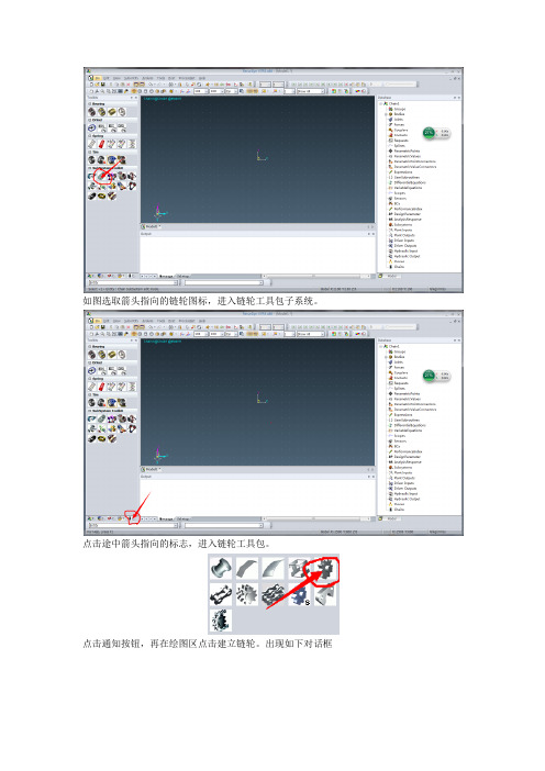
如图选取箭头指向的链轮图标,进入链轮工具包子系统。
点击途中箭头指向的标志,进入链轮工具包。
点击通知按钮,再在绘图区点击建立链轮。
出现如下对话框点击如图所示的下拉菜单,因为我们选在的是ISO606的链条,所以这里我们可以选择ISO606 library。
在途中圈选的地方输入链节、滚子直径及齿数参数,点击Update from ISO 606 Lib按钮就可自动生成其他参数。
参数自动生成后,链轮基本建立完成,但是要注意上图中圈选出来的参数。
要根据所选链板之间的距离设定。
不然在后期会出现干涉,导致无法仿真。
右击各项目会出现下拉菜单,出现属性选项,可以调整其坐标来设定中心距等参数。
点击途中按钮,在绘图区单击建立单链节,出现如下对话框:点击下拉菜单,根据需求选择相应的链节。
单击途中链轮装配按钮,然后依次选取两个链轮,就可以自动完成链轮的装配。
图中箭头指向是比较重要的参数。
链节数量的调整有利于后期啮合的调整。
点击ok,出现如下结果:点击图中按钮,出现如下对话框:选择旋转中心轴,设定旋转角度。
对已经建立的链轮进行旋转,使得其与链节在初始位置时相互啮合。
这一步非常重要,同时也很需要耐心。
点击此按钮,然后添加相关约束及载荷。
如图,点击转动付,然后点击链轮中心轴添加转动副。
点击force模块中的转矩按钮在点击中心轴添加转矩。
在database中右击属性添加相应的驱动及其他载荷的方程。
一切完成之后就可以点击下图中的按钮进行仿真。
分析完成之后,可以右击下图中圈选的部分,弹出图中对话框如上对话框中可以选择仿真结果的输出项。
单击上图中的按钮可以绘制仿真结果的界面。
如下图所示:右侧可以选择你需要输出的结果,还可以显示表格,如图中下方所示,方便读取相关数据。
到此recurdyn动力学仿真分析完成。
从以上的分析过程我们就可以得到在链轮转动过程中,其每个链齿所受力的分布情况,接下来我们借助ANSYS WORKBENCH对其静强度进行分析。
RecurDyn轴承仿真解决方案——新一代虚拟样机系统软件RecurDyn在轴承仿真中的应用
轴承仿真的难点:
理想结果
现实难点
可靠!
不可靠…
由于轴承滚子、滚道与保持架之间有 着非常复杂的动力学关系,所以轴承 仿真的难点主要在动力学问题方面
ENGINEERING COMPUTER SERVICES
上海 北京 深圳 台北 台中 高雄 新加坡
二、RecurDyn与轴承仿真
RecurDyn简介:
❖ FunctionBay Inc. 研发和行销的唯一产品 —— RecurDyn
常见故障 本质原因 诱发原因
塑性变形 过热 磨损
疲劳破坏 松动
过载荷 润滑失效 材料疲劳 装配公差
刚/强度差 滑油泄漏 异物污染
腐蚀 交变载荷
问题所在
结构与材 料问题
密封问题
制造/使用
ENGINEERING COMPUTER SERVICES
上海 北京 深圳 台北 台中 高雄 新加坡
一、仿真技术与轴承 仿真技术如何解决轴承问题:
ENGINEERING COMPUTER SERVICES
上海 北京 深圳 台北 台中 高雄 新加坡
二、RecurDyn与轴承仿真 仿真技术的发展:
ENGINEERING COMPUTER SERVICES
上海 北京 深圳 台北 台中 高雄 新加坡
二、RecurDyn与轴承仿真 传统轴承仿真软件方案及流程:
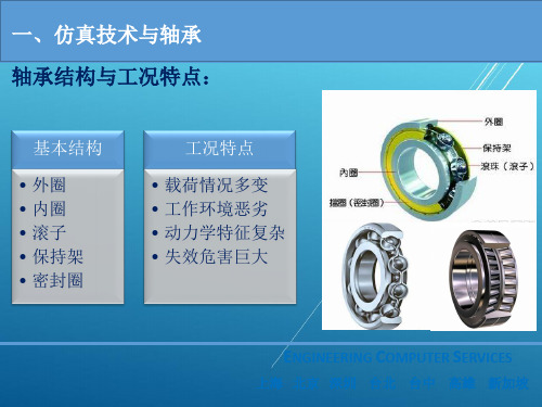
一、仿真技术与轴承 轴承结构与工况特点:
基本结构
• 外圈 • 内圈 • 滚子 • 保持架 • 密封圈
工况特点
• 载荷情况多变 • 工作环境恶劣 • 动力学特征复杂 • 失效危害巨大
ENGINEERING COMPUTER SERVICES
上海 北京 深圳 台北 台中 高雄 新加坡
基于Recurdyn的回转起重机仿真研究

基于Recurdyn的回转起重机仿真研究作者:洪斯玮陈亮朱钰来源:《科技资讯》2016年第21期摘要:回转起重机在工作的过程中,由于离心力和惯性力的作用,会导致吊物摆动。
吊物的摆动会对起重机产生冲击载荷,影响起重机的工作效率和安全性能。
该文采用Recurdyn 及Recurdyn/Belt模块建立集刚柔于一体的回转起重机动力学仿真模型。
通过对模型的仿真研究得出回转起重机的回转机构运动对吊物的摆动影响最大。
关键词:回转起重机 Recurdyn 刚柔耦合中图分类号:TP391 文献标识码:A 文章编号:1672-3791(2016)07(c)-0044-03Abstract: In the process of working, the revolving crane can lead to swing of suspended matter due to the action of centrifugal force and inertia force. The swinging of the suspended matter will have impact load on the crane, which will affect the working efficiency and safety performance of the crane. This paper adopts rotary crane dynamics simulation model of Recurdyn andRecurdyn/Belt to build the rigid flexible set in one of the. Through the simulation of the model, it is concluded that the swing mechanism of the rotary crane is the biggest influence on the swing of the swing.Key Words: Revolving crane; Recurdyn; Rigid flexible coupling回转式起重机如汽车起重机,港口的门座式起重机等在作业的过程中吊物会绕吊臂顶点摆动,吊物的摆动会影响起重机的工作效率及安全性能。
多体动力学仿真 LM
一、前言RecurDyn 软件是韩国FunctionBay公司的旗舰产品,是新一代的多体动力学仿真分析软件,它采用全新的运动方程理论和完全递归算法,计算极其快速稳定,非常适合于求解大规模的多体系统动力学问题,尤其是接触问题和柔性多体动力学问题。
RecurDyn 为用户提供许多方便使用的功能(如亲切的用户界面、丰富的函数库、子系统建模、图形分层等),建模快捷、方便、直观、准确。
RecurDyn软件与各类CAD/CAE软件及液压控制软件等均有非常良好的接口关系,且其高效的求解效率使得多软件联合仿真解决大规模问题和实时仿真成为可能。
由于软件在理论上的先进性、良好的建模界面及接口关系,在国内外获得充分肯定与认同,目前已广泛应用于航空航天、军事车辆、军事装备、工程机械、电器设备、娱乐设备、汽车卡车、铁道、船舶机械及其他通用机械等领域。
利用RecurDyn软件,建立起液压发掘机械“Zaxis200”的动力学模型。
模型包含两条履带系统和底盘系统,并考虑了车架及履带系统中轮架的柔性变形。
仿真分析了加速行进过坎的振动情况,通过与实际测量数据进行比较,模型的准确性得到有效验证。
二、建模通常,液压发掘机械的履带系统并不象汽车一样有弹簧、阻尼一类的悬挂系统。
变形主要集中在车架和履带系统中承重轮架上,因此准确的动力学仿真分析是有必要考虑它们的弹性变形的。
RecurDyn动力学软件可以方便地与MSC/NASTRAN、ANSYS、I-DEAS等有限元分析软件接口,将有限元模型传递到RecurDyn软件中来,从而建立起含柔性零部件的刚柔耦合机械系统。
本例中柔性体从MSC/NASTRAN中生成(见图1)。
履带系统如履带片、承重轮、主动轮等为刚体(见图2),均由软件模板生成,建模非常快速有效。
其他部分如配重、发动机体、驾驶舱等用等效的质量、惯量替代,与车架的链接采用相应的弹簧阻尼器以模拟橡胶特性。
图1 车架与轮架的FEM模型图2 履带系统图3 整机模型三、行进过程的动力学仿真分析耐久性测试是每个车型必须考核的标准项目,它的目的是考察每一零部件在振动和冲击作用下是否存在寿命缺陷。
Recurdyn与Matlab连结control倒单摆控制分析仿真教程
Recurdyn/control例題:倒單擺控制分析-使用matlab/simulink(part-1)1.選取inverse_pendulum_i.rdyn項目,按開啟按鈕2.選取Axial項目,產生Axial Force(軸向力)在路面(Base)和台車(Car)之間3.選取Body,Body,Point,Point項目,Body選地面、Body選車子、Point :2000,-100,0、Point : -500,-100,0(注意:軸向力方向(向右為正),因為建立軸向力時,方向是由左到右)4.選取Plant Input項目,按一下Add按鈕5.axial_force是系統的輸入廠(由控制迴路所決定),按一下確定按鈕6.選取Plant Output項目,按一下Add按鈕7.按兩下Add按鈕8.選取項目9. base.Marker1和bird.Marker1項目10.選取文字方塊,az(2,1):單擺的角度值,是系統的輸出廠(由RecurDyn計算),name:angle,按一下OK按鈕11.Plant Output List對話方塊開啟了,按一下確定按鈕12.選取axial1項目13.按一下EL按鈕14. 開啟Expression List對話方塊,按一下Create按鈕15. 開啟Expression對話方塊,按一下Add按鈕16. 軸向力內存函數是:pin(1);pin就是:Plant of Input,(1):就是axial_force。
選取文字方塊:pin(1)。
按一下OK按鈕17. 按一下確定按鈕18. 按一下確定按鈕19. 選取Cosim項目20. 選取Simulink項目,由Simulink啟動RecurDyn21. 輸出matlab*.m檔案,選取m-file to create plant block文字方塊,按delete鍵,輸入inverse_pendulum,按一下Export按鈕22. 按一下儲存(s)按鈕23. 按一下套用(A)按鈕,再按一下取消按鈕24. 記得存檔,關閉RecurDyn軟體------------------------------------------------------------------------------------------------------- Recurdyn/control例題:倒單擺控制分析-使用matlab/simulink(part-2)1.載入:inverse_pendulum.m2.鍵入:rdlib,rdlib是recurdyn plant控制,按enter鍵3.recurdyn_plant_7_視窗開啟4.鍵入:simulink,啟動simulink,按enter鍵5.simulink library browser視窗開啟,按一下simulink library browser按鈕6.按一下create a new model按鈕7.untitled視窗開啟8.拉進recurdyn plant,選取選項,建立pid迴路去控制軸向力大小,讓單擺可以動平衡9.選取Gain圖案進來,按ctrl+c鍵10.選取選項continuous\derivative、integrator圖案進來11.選取項目math operations\add圖案進來12.選取項目commonly used blocks\scope圖案進來,按ctrl+v鍵13.按add圖案快按兩下,function block parameters:add視窗開啟了,將++改成---,按一下OK按鈕14.連好線15.按Gain圖案快按兩下,function block parameters:gain視窗開啟,將1改成200,按一下OK按鈕16.按Gain1圖案快按兩下,function block parameters:gain視窗開啟,將1改成1,按一下OK按鈕17.按Gain2圖案快按兩下,function block parameters:gain視窗開啟,將1改成5,按一下OK按鈕18.按一下save(ctrl+s)按鈕19.輸入inverse_pendulum檔名,按Enter按鈕20.快按recurdyn plant block兩下,inverse_pendulum/recurdyn plant block視窗開啟,recurdyn plant圖案(紅色)是recurdyn與simulink之間的控制核心,快按兩下21. [ ]static analysis(事先進行靜力分析,之後再進行動力分析)[X ]recurdyn_show(計算過程可以啟動recurdyn畫面)[X ]recurdyn_animation(計算過程可以顯示動畫)之後按一下cancel按鈕,按一下關閉按鈕22.模擬時間5,按一下Start simulation按鈕23. RecurDyn 6.4視窗開啟,RecurDyn會自動載入模型,且可以看到計算過程中的動畫(很快就結束所以省略)24.快按scope圖案兩下,scope視窗開啟(scope是角度位移變化、scope1是軸向力輸出變化),Finish。
基于RecurDyn的多体动力学仿真
基于RecurDyn的多体动力学仿真基于RecurDyn的多体动力学仿真大规模复杂的多体系统动力学问题,尤其是复杂的多接触问题是动力学分析的难点,本文对链式输送机构应用RecurDyn软件,在导入原有实体模型的基础上,快速构建仿真模型,结果另人满意。
产品开发工程师经常会遇到各种运动机构的动力学分析问题,有些情况过于复杂和特殊,特别是一些链式输送机构的动力学仿真问题,整个系统在高速的运动中涉及到的许多接触碰撞等受力情况会给系统的动力学求解带来极大的困难。
RecurDyn 是新一代的动力学分析软件,采用全新的运动方程理论和完全递归算法,非常适合于求解大规模复杂的多体系统动力学问题,尤其是复杂的多接触问题。
本文对某一形式的链式输送机构借助RecurDyn软件进行了动力学仿真。
一、系统建模该链式输送机构用于高速间歇状态下传输筒型物体,由于系统的运动主要是在一个平面的运动,因此输送带采用具有旋转约束的链节相互联接而成,链节之间加入扭转弹簧以反映平面内的扭转刚度。
每个链节依靠四个抱紧臂弹性固定着传输体,这四个抱紧臂通常可简化成弹性的悬臂曲梁,本例中简化成四个刚性铰接的小爪,并加上涡卷弹簧力,也可以很好地反映出实际情况。
机构的运动是通过输链器装置完成的,主要是通过上方拨动齿的往复运动和下方防止链条反向倒退的阻动齿来共同驱动的。
由于上方拨动齿的位置尚需精确的定位,故将上方拨动齿的运动简化为水平方向的牵引运动。
仿真模型的建立是在导入原有三维精确实体模型的基础上,用RecurDyn提供的多级子系统建模和空间多接触面定义快速构建出的,如图1、图2所示,并在此基础上添加力、碰撞、运动副等约束条件。
由于该机构是高速间歇运动,因此采用一系列分段的时间与运动位移坐标来输入运动参数。
图1 经简化的一对空链节模型二、仿真分析1.运动状态与干涉校验首先必须考虑到链条柔度对运动的干涉影响,即考虑到在设计的平面柔度和扭转柔度范围内,长链条和最后只剩单个链节情况下,链节进入输链器装置内的运动状态,避免被卡住或干涉撞击引起抱紧臂变形。
原理图仿真步骤
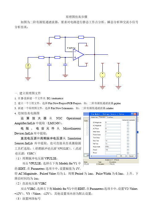
原理图仿真步骤如图为二阶有源低通滤波器,要求对电路进行静态工作点分析、瞬态分析和交流小信号分析仿真:一. 建立原理图文件1. 在D 盘新建一个文件夹 D2:/studenttest2. 建立一个工程文件,选择File/New/Project/PCB Project ,如:二阶有源低通滤波器.prjdoc3. 新建一个原理图文件,选择File/New/Schematic ,如:二阶有源低通滤波器.schdoc4. 绘制仿真电路图运算放大器从NSC OperationalAmplifier.IntLib 中提取(LM324N ); 电阻、电容元件从Miscellaneous Devices.IntLib 库中提取;直流电压源和周期脉冲电压源从SimulationSources.IntLib 库中提取,也可直接从仿真激励源工具栏选取;(周期脉冲电压源VPULSE )、(直流电压源:VSRC )(1)周期脉冲电压源VPULSE :双击VPULSE ,选择右下角Models for V1中的EDIT ,在Parameters 选项卡中,设置幅值为1V ,即AC Magnitude 、Pulsed Value 均为1,周期Period 为1ms ,Pulse Width 为0.5ms ,上升、下降沿时间均为1us ;(2)直流电压源VSRC双击VSRC ,选择右下角Models for V1中的EDIT ,在Parameters 选项卡中,设置V2(Value :+12V )、V3(Value :-12V ),其他设置项内容为默认设置;(3)放置网络标号在输入、输出端分别放置网络标号IN和OUT,用来测试这两个点的仿真数据,原理图绘制结束保存文件。
注意网络标号一定要放在元件的管脚外端点或导线上,否则在【分析设定】对话框的【可用信号】列表框内将不显示。
二. 进行静态工作点分析仿真参数设置单击仿真工具栏按钮,打开静态工作点分析仿真参数设置对话框。
- 1、下载文档前请自行甄别文档内容的完整性,平台不提供额外的编辑、内容补充、找答案等附加服务。
- 2、"仅部分预览"的文档,不可在线预览部分如存在完整性等问题,可反馈申请退款(可完整预览的文档不适用该条件!)。
- 3、如文档侵犯您的权益,请联系客服反馈,我们会尽快为您处理(人工客服工作时间:9:00-18:30)。
RecurDyn運動 RecurDyn運動 模擬分析
題目
2
選擇IPS制 重力設為0 選擇IPS制,重力設為0
3
點選Body→ 點選Body→Link
4
繪製桿件, 繪製桿件,設定桿件數值
5
繪製圓球點選Body→ 繪製圓球點選Bo檢視輸出分析數值
19
10G=3862.2inch/sec^2 找出時間為53.4 找出時間為53.4
20
6
設定球體半徑為桿件端半徑兩倍
7
定圓球中心於(360.0.0) 定圓球中心於(360.0.0)
8
點選Joint→ 點選Joint→Revolute
9
轉軸定在原點,勾選Include 轉軸定在原點,勾選Include Motion
10
設定位移函數
11
點選Joint→ 點選Joint→Fixed
12
將圓球與桿子固定
13
設定數值:End 設定數值:End time 60 ,Step 5000
14
模擬運動狀態
15
點選Post→ 點選Post→Plot
16
檢視圖表:點選Bodies→Body2→ 檢視圖表:點選Bodies→Body2→Acc_TM
17
點選File→Export→ 點選File→Export→Export Curve data
