TCS230颜色传感器的中英文翻译
TCS230的功能

颜色识别是模式识别领域的一个重要研究方向,利用颜色识别技术能使传统依靠人眼进行颜色判别的方法发生根本变革。
这种新型技术采用颜色传感器获取外界的颜色信息,进而通过基于计算机的信号处理技术实现颜色的精确识别。
颜色识别技术经历了传统模拟识别方法和现代数字化识别两个阶段。
传统的颜色识别方法采用模拟颜色探测器件来进行外界颜色获取,这种探测器件通常是在独立的光电二极管上覆盖经过修正的红、绿、蓝滤光片,经过光电转换产生对应的模拟信号;如果用微控制器对这些模拟信号进行处理,就必须采用额外的AD转换电路才能实现和微控制器的接口,而AD转换电路的引入增加了信号的处理时间,对整个系统的速度有很大的影响;此外,由于一般的AD转换存在量化误差,系统的精度受到很大的限制,这些使得传统的颜色识别方法逐渐被现在的数字式化的颜色识别技术所替代。
随着半导体技术的发展,数字式的颜色传感器逐步取代了传统的光电二极管传感器,这种技术把颜色传感器所需的光学、机械、电子等信号处理集成在很小的芯片上极大地缩小了颜色传感器的体积。
由于这种传感器输出的是数字量,因此可以通过数字处理技术来提高探测速度并保持检测器输出信号的精度。
例如采用改进的动态检测方法来提高颜色探测的速度,采用数字电路来处理颜色数据等。
虽然数字传感器已经取得了一些成功,但其应用于市场的技术还不够成熟,随着美国TAOS(Texas Advanced Optoelectronic Solutions)公司最新推出的颜色传感器TCS230的面世,数字传感器才真正被工程师们采用。
这种颜色传感器具有分辨率高、可编程的颜色选择、数字输出等特点。
本文采用TCS230来作为系统的探测部分,基于该器件设计的颜色识别系统可以应用于军事领域,也可以应用于电致变色材料的变色研究以便获得材料的变色参数。
1 TCS230简介1.1 主要特性TCS230是美国TAOS公司推出的可编程光到频率的转换器。
它把可配置的硅光电二极管与电流频率转换器集成在一个单一的CMOS(Comple-mentary Metal Oxide Semiconductor)电路上,同时在单一芯片上还集成了红、绿、蓝(RGB)3种滤光器,是业界第一个有数字兼容接口的RGB颜色传感器。
tcs230颜色传感器文档

TCS230D SOP8 颜色传感器1概述TCS230是TAOS公司最新推出的业界首款带数字兼容接口的RGB彩色光/频率转换器,它内部集成了可配置的硅光电二极管阵列和一个电流/频率转换器,其结构框图如图1所示。
TCS230输出为占空比50%的方波,且输出频率与光强度成线性关系。
该转换器对光响应范围为250 000~1,典型输出频率范围为2Hz~500kHz,用户可通过两个可编程引脚来选择100%、20%或2%的输出比例因子。
TCS230的输入输出引脚可直接与微处理器或其他逻辑电路连接。
通过输出使能端OE将输出置于高阻状态可使多个器件共享一条微处理器输入线。
TCS230可编程彩色光/频率转换器将红、绿和蓝滤波器集成在单芯片上,因此无需ADC就可实现每彩色信道10位以上的分辨率。
芯片内含一个交叉连接的8×8光电二极管阵列,其中每16个二极管提供一种色彩类型,共有红、蓝、绿和清除全部光信息四种类型,可最大限度地降低入射光幅射的不均匀性。
所有同颜色的16个光电二极管都是并联连接,工作时通过可编程的引脚来动态选择色彩,以此来增加精确度和简化光学电路。
该芯片采用8引脚SOIC表面贴封装,适用于色度计的测量应用。
TCS230的主要特点如下:●可完成高分辨率的光照度/频率转换;●色彩和满度输出频率可编程调整;●可直接与微处理器通讯;●单电源工作,工作电压范围:2.7V~5.5V;●具备掉电恢复功能;●50kHz时非线性误差的典型值为0.2%;●稳定的200ppm/℃的温度系数。
2TCS230的引脚功能TCS230的引脚排列如图2所示,各管脚的功能描述见表1所列。
表1TCS230管脚功能引脚号符号类型功能说明1S0I输出频率分频系数选择输入端2S1I3OE I输入频率使能端。
低电平有效4GND电源地5VDD电源电压6OUT O输出频率(fo)7S2I光电二极管类型选择输入端8S3I3TCS230的主要参数3.1电学特性参数TCS230在TA=25℃ VDD=5V条件下的电学特性如表2所列。
Arduino 颜色传感器

白平衡就是告诉系统什么是白色。从理论上讲,白色是由等量的红色、绿色和蓝色混合而成的;但实际上,白色中的三原色并不完全相等,并且对于TCS230的光传感器来说,它对这三种基本色的敏感性是不相同的,导致TCS230的RGB输出并不相等,因此在测试前必须进行白平衡调整,使得TCS230对所检测的“白色”中的三原色是相等的。进行白平衡调整是为后续的颜色识别作准备。在本装置中,白平衡调整的具体步骤和方法如下:将空的试管放置在传感器的上方,试管的上方放置一个白色的光源,使入射光能够穿过试管照射到TCS230上;根据前面所介绍的方法,依次选通红色、绿色和蓝色滤波器,分别测得红色、绿色和蓝色的值,然后就可计算出需要的三个调整参数。
g_SF[1] = 255.0/ g_array[1] ; //G Scale factor
g_SF[2] = 255.0/ g_array[2] ; //B Scale factor
Serial.println(g_SF[0]);
Serial.println(g_SF[1]);
Serial.println(g_SF[2]);
{
if(Level01 != 0)
Level01 = HIGH;
if(Level02 != 0)
Level02 = HIGH;
digitalWrite(S2, Level01);
digitalWrite(S3, Level02);
}
void TSC_Count()
{
g_count ++ ;
}
void TSC_Callback()
#define S0 6 // Please notice the Pin's define
基于TCS230颜色传感器的颜色识别器设计

颜色别传感器又称作色彩传感器色。目前通用的颜色测量方法是采用通过测量待测颜色的三个基本颜色的频率输入到单片机等处理器中进行数据处理,得到三基色的值,通过仿真软件或RGB颜色对应表将三基色按所测数据合,从而成得到样品的颜色。
目前市面上常见的色颜色传感器大致有两种类型:一种是RGB(红、绿、蓝)三基色型颜色传感器,通过检测带测光的红、绿、蓝三基色刺激值来识别颜色; 另一种为色差传感器,主要通过测量待测物体颜色与基准颜色之间的色差来识别颜色。下边简要介绍三种常见的颜色传感器的设计方案:
1.2
颜色识别技术是新兴检测技术,在彩色打印、商标识别和材料分拣等方面已在我国拥有广泛应用。虽然我国在机器人视觉系统领域已取得举世瞩目的成就,但是在高分辨的颜色识别方面仍然缺乏自主研发能力。高精度的颜色识别技术仍然由少数发达国家掌控,我国高分辨率颜色传感器的研究工作任重而道远。
颜色识别系统提出的时间较晚,出现在自动控制系统之后。其作为一种新兴的检测技术也是控制理论的简单应用,经过几十年的发展,在工业控制中逐渐开始大范围的应用。颜色传感器在实时检测系统以及自动控制方面有着重要的意义,伴随着单片机等处理器技术的发展,颜色识别系统的效率也大大的增加。颜色识别在现代生产中的应用愈加广泛,特别是在遥感技术、工业过程控制、材料分拣、图像处理、机器人视觉系统等方面的起着重要的作用,颜色传感器的快速发展为上述生产应用自动化的实现提供了可能。随着颜色传感器的广泛应用,颜色识别技术已成为工业自动化必不可少的部分,发展前景十分广阔。
RGB颜色模型如下图2.1所示。由三基色原理可知自然界中所有色光都可由R、G、B三种基本颜色按照不同的比例叠加合成,当三基色分量都为0时,叠加出的光为黑色,对应于立方体坐标中的(0,0,0)点;当三基色分量都为255时,叠加出的光为白色光,对应于立体坐标中得(255,255,255)。以由黑到白为对角线的正方体的其他六个顶点分别为红(255,0,0),黄(255,255,0),绿(0,255,0),青(0,255,255),蓝(0,0,255)和品红(255,0,255)。每个颜色都有其独自RGB值。
传感器中英文介绍

传感器中英文介绍Company Document number:WTUT-WT88Y-W8BBGB-BWYTT-19998. sensorssensors(English name: transducer/sensor) is a kind of detection device, can feel the measured information, and will feel information transformation according to certain rule become electrical signal output, or other form of information needed to satisfy the information transmission, processing, storage, display, record and control requirements.Sensor's features include: miniaturization, digital, intelligent, multi-functional, systematic and network. It is the first step of automatic detection and automatic control. The existence and development of the sensor, let objects have sensory, such as touch, taste and smell let objects become live up slowly. Usually according to its basic cognitive functions are divided into temperature sensor, light sensor, gas sensor, force sensor, magnetic sensor, moisture sensor, acoustic sensor, radiation sensitive element, color sensor and sensor etc. 10 major categories.temperature transducerTemperature sensors (temperature transducer) refers to can feel temperature translates into usable output signal of the sensor. The temperature sensor is the core part of the temperature measuring instrument, wide variety. According to measuring methods could be divided into two types: contact and non-contact, according to the sensor material and electronic component features divided into two categories, thermal resistance and thermocouple.1 principle of thermocoupleThermocouple is composed of two different materials of metal wire, the welded together at the end. To measure the heating part of the environment temperature, can accurately know the temperature of the hot spots. Because it must have two different material of the conductor, so called the thermocouple. Different material to make the thermocouple used in different temperature range, their sensitivity is also each are not identical. The sensitivity of thermocouple refers to add 1 ℃ hot spot temperature changes, the output variation of potential difference. For most of the metal material support thermocouple, this value about between 5 ~ 40 microvolt / ℃.As a result of the thermocouple temperature sensor sensitivity has nothing to do with the thickness of material, use very fine material also can make the temperature sensor. Also due to the production of thermocouple metal materials have good ductility, the slight temperature measuring element has high response speed, can measure the process of rapid change.Its advantages are:(1)high precision measurement. Because of thermocouple direct contact with the object being measured, not affected by intermediate medium.(2)the measurement range. Commonly used thermocouple from 1600 ℃ to50 ℃ ~ + sustainable measurement, some special thermocouple minimum measurable to - 269 ℃ ., gold iron nickel chrome), the highest measurable to + 2800 ℃ (such as tungsten rhenium).(3) simple structure, easy to use. Thermocouple is usually composed of two different kinds of metal wire, but is not limited by the size and the beginning of, outside has protective casing, so very convenient to use. The thermocouple type and structure of the form.2. The thermocouple type and structure formation(1)the types of thermocoupleThe commonly used thermocouple could be divided into two types: standard thermocouple and non-standard thermocouple. Standard thermocouple refers to the national standard specifies its thermoelectric potential and the relationship between temperature, permissible error, and a unified standard score table of thermocouple, it has with matching display instrument to choose from. Rather than a standard thermocouple or on the order of magnitude less than the range to use standardized thermocouple, in general, there is no uniform standard, it is mainly used for measurement of some special occasions.Standardized thermocouple is our country from January 1, 1988, thermocouple and thermal resistance of all production according to IEC international standard, and specify the S, B, E, K, R, J, T seven standardization thermocouple type thermocouple for our country unified design.(2)to ensure that the thermocouple is reliable, steady work, the structure of thermocouple requirements are as follows:①of the two thermocouple thermal electrode welding must be strong;②two hot electrode should be well insulated between each other, in case of short circuit;③compensation wires connected to the free cod of a thermocouple to convenient and reliable;④protect casing thermal electrodes should be able to make sufficient isolation and harmful medium.3.The thermocouple cold end temperature compensationDue to the thermocouple materials are generally more expensive (especially when using precious metals), and the temperature measurement points are generally more far, the distance to the instrument in order to save materials, reduce cost, usually adopt the compensating conductor) (the free end of the cold junction of the thermocouple to the steady control of indoor temperature, connected to the meter terminals. It must be pointed out that the role of the thermocouple compensation wire extension hot electrode, so that only moved to the control room of the cold junction of the thermocouple instrument on the terminal, it itself does not eliminate the cold end temperature change on the influence of temperature, cannot have the compensation effect. So, still need to take some of the other correction method to compensate of the cold end temperature especially when t0 indicates influence on measuring temperature 0 ℃.Must pay attention to when using thermocouple compensating conductor model match, cannot be wrong polarity, compensation conductor should be connected to the thermocouple temperature should not exceed 100 ℃.传感器传感器(名称:transducer/sensor)是一种检测装置,能感受到被测量的信息,并能将感受到的信息,按一定规律变换成为电信号或其他所需形式的信息输出,以满足信息的传输、处理、存储、显示、记录和控制等要求。
TCS230颜色识别—原理—程序

/********************************************/
void main(void)
{
port_init();
int2_init();
timer1_init();
Init_12864();
LcmClearTXT(); //文本区清RAM函数
Display_x_y_data(0,0,"颜色识别:");
Display_x_y_data(1,0,"红色成分:");
Display_x_y_data(2,0,"蓝色成分:");
Display_x_y_data(3,0,"绿色成分:");
S2=0;//先检测红色(S2,S3=0,0)
S3=0;
SEI();
void timer1_init()
{
TCCR1B = 0X02;//设置分频数为8
TCNT1H = 0x63;//设置计数初值,定时20ms
TCNT1L = 0xC0;
}
/*******************************************
*函数名称: port_init()
*函数功能:端口初始化Fra bibliotekEIMSK |= BIT(2); //打开外部中断
TIMSK |= BIT(2);//打开溢出中断
while(1);
}
/*******************************************
*函数名称: interrupt_int2()
*函数功能:
*入口参数:无
*出口参数:无
汽车传感器中英文

汽车传感器中英文曲轴转速传感器 crankshaft sensor凸轮轴位置传感器 camshaft sensor节气门位置传感器 throttle position sensor爆震传感器 knock sensor (or detonation sensor)进气温度传感器 intake air temperature sensor进气歧管绝对压力传感器manifold absolute pressure sensor (manifold vacuum sensor) 空气流量计 air flow sensor质量型空气流量传感器 air mass sensor加速踏板位置传感器 accelerator pedal position sensor轮速传感器 wheel speed sensor车速传感器 vehicle speed sensor空气传感器 air sensor环境温度传感器 ambient sensor大气压力传感器 barometric pressure sensor双金属式温度传感器 bimetallic sensor增压器传感器 boost sensor冷却水温传感器 coolant temperature sensor曲轴传感器 crank sensor碰撞传感器 crash sensor (or impact sensor)汽缸传感器 cylinder sensor排气再循环功能传感器 erg function sensor发动机转速传感器 engine speed sensor发动机温度传感器 engine temperature sensor离地间隙传感器 ground clearance sensor霍尔效应传感器 hall-effect sensor霍尔传感器 hall sensor加热式氧传感器 heated exhaust gas oxygen sensor热氧传感器 heated oxygen sensor侧向加速度感测器 lateral acceleration sensor车内传感器 in-car sensor歧管空气温度感测器 manifold air temperature sensor进气温度传感器 manifold charge temperature sensor进气歧管温度传感器 manifold surface temperature sensor 机油油位传感器 oil level sensor机油压力传感器 oil pressure sensor大气压力传感器 atmospheric pressure sensor压差传感器 pressure differential sensor基准传感器 reference mark sensor转向压力传感器 steering pressure sensor开关传感器 switching sensor叶轮空气温度传感器 vane air temperature sensor可变磁阻传感器 variable reluctance sensor车轮滑动传感器 wheel slip sensor横摆传感器 yaw sensor热膜传感器 hot-film sensor燃油压力传感器 fuel pressure sensor (regulator)上止点传感器 TDC sensor轮胎气压传感器 tire pressure sensor防抱死制动传感器 anti-lock brake sensor差速防滑传感器 differential antiskid sensor背压[排气压力]传感器back pressure transducer堵塞报警传感器 clog warning sensor燃料成分传感器 fuel composition sensor(燃油系)燃油不足[低限]传感器 fuel low—level sensor玻璃破裂传感器 glass breakage sensor(悬架)调平[高度]传感器 leveling sensor液面[位]传感器 level sensor灯光故障传感器 light failure sensor负[载]荷传感器 load sensor主氧传感器 main oxygen sensor相位传感器 phase sensor光电传感器 photo(electric)sensor催化转化器前氧传感器 pre-catalyst lambda probe(刮水器)雨滴传感器 raindrop sensor(悬架)行驶高度传感器ride-height sensor车内温度传感器 room temperature sensor安全传感器 safety sensor副氧传感器(装在催化转化器出口后面) sub-oxygen sensor 悬架位移传感器 suspension sensor油箱(贮液罐]液面[位]传感器 tank-level sensor转[扭]矩传感器 torque sensor燃油水分传感器 water in-fuel detector[sensor]磨损传感器 wear sensor空气滤清器堵塞报警传感器 air filter clog warning sensor 车距传感器 distance sensor停车传感器 park sensor变速范围传感器 transmission range sensor。
TCS230颜色识别产品使用手册
#include <reg52.h>
#define uchar unsigned char
#define uint unsigned int
uchar duan[10]={0xc0,0Xf9,0xa4,0xb0,0x99,0x92,0x82,0xf8,0x80,0x90};//所需的段的位码
uchar wei[5]={0Xf7,0XEf,0XDf,0XBf,0X7f}; //位的控制端
uint z,x,c,v,b,n,date;//定义数据类型
uint dispcount=0;//中断计数
uint lck=0;//定时器计数
uint disp=0;//频率值
/******************************************************************
void main(void)
{
IT0=1; //INT0下降沿中断
EX0=1; //允许INT1中断
initTimer(); //装入初值
TR0=1;
ET0=1;
EA=1;
while(1)
{
date=disp;
xianshi();
}
}
/*************************************************************************
数码管动态扫描
*********************************************************************/
(完整word版)颜色传感器TCS230中文资料(word文档良心出品)

颜色传感器TCS230及颜色识别电路随着现代工业生产向高速化、自动化方向的发展,生产过程中长期以来由人眼起主导作用的颜色识别工作将越来越多地被相应的颜色传感器所替代。
例如:图书馆使用颜色区分对文献进行分类,能够极大地提高排架管理和统计等工作;在包装行业,产生包装利用不同的颜色和装潢来表示其不同的性质或用途。
目前的颜色传感器通常是在独立的光电二极管上覆盖经过修正的红、绿、蓝滤波片,然后对输出信号进行相应的处理,才能将颜色信号识别出来;有的将两者集合起来,但是输出模拟信号,需要一个A/D电路进行采集,对该信号进一步处理,才能进行识别,增加了电路的复杂性,并且存在较大的识别误差,影响了识别的效果。
TAOS(Texas Advanced Optoelectronic Solutions)公司最新推出的颜色传感器TCS230,不仅能够实现颜色的识别与检测,与以前的颜色传感器相比,还具有许多优良的新特性。
1 .TCS230芯片的结构框图与特点:TCS230是TAOS公司推出的可编程彩色光到频率的转换器,它把可配置的硅光电二极管与电流频率转换器集成在一个单一的CMOS电路上,同时在单一芯片上集成了红绿蓝(RGB)三种滤光器,是业界第一个有数字兼容接口的RGB彩色传感器,TCS230的输出信号是数字量,可以驱动标准的TTL或CMOS逻辑输入,因此可直接与微处理器或其他逻辑电路相连接,由于输出的是数字量,并且能够实现每个彩色信道10位以上的转换精度,因而不再需要A/D转换电路,使电路变得更简单,图1是TCS230的引脚和功能框图。
图1中,TCS230采用8引脚的SOIC表面贴装式封装,在单一芯片上集成有64个光电二极管,这些二极管分为四种类型,其16个光电二极管带有红色滤波器;16个光电二极管带有绿色滤波器;16个光电二极管带有蓝色滤波器,其余16个不带有任何滤波器,可以透过全部的光信息,这些光电二极管在芯片内是交叉排列的,能够最大限度地减少入射光辐射的不均匀性,从而增加颜色识别的精确度;另一方面,相同颜色的16个光电二极管是并联连接的,均匀分布在二极管阵列中,可以消除颜色的位置误差。
光电传感器(中英文对照版)
Photoelectric sensorKey word: photoelectric effect photoelectric element photoelectric sensor classification sensor application characteristics .Abstract: in the rapid development of science and technology in the modern society, mankind has into the rapidly changing information era, people in daily life, the production process, rely mainly on the detection of information technology by acquiring, screening and transmission, to achieve the brake control, automatic adjustment, at present our country has put detection techniques listed in one of the priority to the development of science and technology. Because of microelectronics technology, photoelectric semiconductor technology, optical fiber technology and grating technical development makes the application of the photoelectric sensor is growing. The sensor has simple structure, non-contact, high reliability, high precision, measurable parameters and quick response and more simple structure, form etc, and flexible in automatic detection technology, it has been widely applied in photoelectric effect as the theoretical basis, the device by photoelectric material composition.Text:First, theoretical foundation - photoelectric effectPhotoelectric effect generally have the photoelectric effect, optical effect, light born volts effect.The light shines in photoelectric material, according to the electronic absorption material surface energy, if absorbed energy large enoughelectronic electronic will overcome bound from material surface and enter the outside space, which changes photoelectron materials, this kind ofphenomenon become the conductivity of the photoelectric effectAccording to Einstein's photoelectron effect, photon is moving particles, each photon energy for hv (v for light frequency, h for Planck's constant, h = 6.63 * 10-34 J/HZ), thus different frequency of photons have different energy, light, the higher the frequency, the photon energy is bigger. Assuming all the energy photons to photons, electronic energy will increase, increased energy part of the fetter, positive ions used to overcome another part of converted into electronic energy. According to the law of conservation of energy:Type, m for electronic quality, v for electronic escaping the velocity, A microelectronics the work done.From the type that will make the optoelectronic cathode surface escape thenecessary conditions are h > A. Due to the different materials have different escaping, so reactive to each kind of cathode materials, incident light has a certain frequency is restricted, when the frequency of incident light under this frequency limit, no matter how the light intensity, won't produce photoelectron launch, this frequency limit called "red limit". The corresponding wavelength forA-h m 212νν=type, c for the speed of light, A reactive for escaping.When is the sun, its electronic energy, absorb the resistivity reduce conductive phenomenon called optical effects. It belongs to the photoelectric effect within. When light is, if in semiconductor electronic energy big with semiconductor of forbidden band width, the electronic energy from the valence band jump into the conduction band, form, and at the same time, the valence band electronic left the corresponding cavities. Electronics, cavitation remained in semiconductor, and participate in electric conductive outside formed under the current role.In addition to metal outer, most insulators and semiconductor have photoelectric effect, particularly remarkable, semiconductor optical effect according to the optoelectronics manufacturing incident light inherent frequency, when light resistance in light, its conductivity increases, resistance drops. The light intensity is strong, its value, if the smaller, its resistance to stop light back to the original value.Semiconductor produced by light illuminate the phenomenon is called light emf, born volts effect on the effect of photoelectric devices have made si-based ones, photoelectric diode, control thyristor and optical couplers, etc. Second, optoelectronic components and characteristicsAccording to the outside optoelectronics manufacturing optoelectronic devices have photoelectron, inflatable phototubes and photoelectric times once tube. 1. Phototubes phototubes are various and typical products are vacuumphototubes and inflatable phototubes, light its appearance and structure as shown in figure 1 shows, made of cylindrical metal half cathodic K and is located in the wires cathodic axis of anode in A package of smoke into the vacuum, when incident light within glass shell in the cathode, illuminate A single photon took all of its energy transfer to the cathode materials A free electrons, so as to make the freedom electronic energy increase h. When electrons gain energy more than escape of cathode materials, it reactive A metal surface constraints can overcome escape, form electron emission. This kind of electronic called optoelectronics, optoelectronic escaping the metal surface for after initial kinetic energyPhototubes normal work, anode potential than the cathode, shown in figure 2. In one shot more than "red light frequency is premise, escape from the optoelectronic cathode surface by positive potential attracted the anode in photoelectric tube forming space, called the current stream. Then if light intensity increases, the number of photons bombarded the cathode multiplied, unit of time to launch photoelectron number are also increasing, photo-current greatens. In figure 2 shows circuit, current and resistance is the voltage drop across the only a function of light intensity relations, so as to achieve a photoelectric conversion. When the LTT optoelectronic cathode K, electronic escape from the cathode surface, and was the photoelectric anode is an electric current, power plants absorb deoxidization device in the load resistance - I, the voltagePhototubes photoelectric characteristics fig.03 shows, from the graph in flux knowable, not too big, photoelectric basic characteristics is a straight line.2. Photoelectric times had the sensitivity of vacuum tube due to low, so with people developed has magnified the photomultiplier tubes photo-current ability. Figure 4 is photomultiplier tube structure schematic drawing.图4光电倍增结构示意图From the graph can see photomultiplier tubes also have A cathode K and an anode A, and phototubes different is in its between anode and cathode set up several secondary emission electrodes, D1, D2 and D3... They called the first multiply electrode, the second multiply electrode,... Usually, double electrode for 10 ~ 15 levels. Photomultiplier tubes work between adjacent electrode, keeping a certain minimum, including the cathode potential potentials, each multiply electrode potential filtering increases, the anode potential supreme. When the incident light irradiation, cathodic K escape from the optoelectronic cathode multiplied by first accelerated, by high speed electrode D1 bombarded caused secondary electron emission, D1, an incident can generate multiplesecondary electron photonics, D1 emit of secondary electron was D1, D2 asked electric field acceleration, converged on D2 and again produce secondary electron emission... So gradually produce secondary electron emission, make electronic increased rapidly, these electronic finally arrived at the anode, form a larger anode current. If a n level, multiply electrodes at all levels for sigma, the multiplication of rate is the multiplication of photomultiplier tubes can be considered sigma n rate, therefore, photomultiplier tube has high sensitivity. In the output current is less than 1mA circumstances, it in a very wide photoelectric properties within the scope of the linear relationship with good. Photomultiplier tubes this characteristic, make it more for light measurement.3 and photoconductive resistance photoconductive resistance within the working principle is based on the photoelectric effect. In semiconductor photosensitive material ends of mount electrode lead, it contains transparent window sealed in the tube and shell element photoconductive resistance. Photoconductive resistance properties and parameters are:1) dark resistance photoconductive resistance at room temperature, total dark conditions stable resistance called dark resistance, at the current flow resistance is called dark current.2) light resistance photoconductive resistance at room temperature and certain lighting conditions stable resistance measured, right now is called light resistance of current flow resistance is called light current.4, volt-ampere characteristics of both ends photoconductive resistance added voltage and current flows through photoconductive resistance of the relationship between called volt-ampere characteristics shown, as shown in figure 5. From the graph, the approximate linear volt-ampere characteristics that use should be limited, but when the voltage ends photoconductive resistance, lest than shown dotted lines of power consumption area5, photoelectric characteristics photoconductive resistance between the poles, light when voltage fixed the relationship between with bright current photoelectric characteristics. Called Photoconductive resistance photoelectric characteristics is nonlinear, this is one of the major drawback of photoconductive resistance.6, spectral characteristics is not the same incident wavelength, the sensitivity of photoconductive resistance is different also. Incidence wavelength and photodetector the relationship between relative sensitivity called spectral characteristics. When used according to the wavelength range by metering, choose different material photoconductive resistance.7, response time by photoconductive resistance after photo-current need light,over a period of time (time) rise to reach its steady value. Similarly, in stop light photo-current also need, over a period of time (down time) to restore the its dark current, this is photoconductive resistance delay characteristics. Photoconductive resistance rise response time and falling response time about 10-1 ~ 10-3s, namely the frequency response is 10Hz ~ 1000Hz, visible photoconductive resistance cannot be used in demand quick response occasion, this is one of the main photoconductive resistance shortcomings.8 and temperature characteristic photoconductive resistance by temperature affects greatly, temperature rise, dark current increase, reduced sensitivity, which is another photoconductive resistance shortcomings.9, frequency characteristic frequency characteristics refers to an external voltage and incident light, strong must be photo-current I and incident light modulation frequency, the relationship between the f, photoelectric diode is the frequency characteristic of the photoelectric triode frequency characteristics, this is because of the photoelectric triode shot "yankees there capacitance and carrier base-combed need time's sake. By using the principle of the photoelectric efficiency of optoelectronics manufacturing frequency characteristics of the worst, this is due to capture charge carriers and release charge need a certain time's sake.Three, photoelectric sensorsPhotoelectric sensor is through the light intensity changes into electrical signal changes to achieve control, its basic structure, it first figure 6 by measuring thechange of change of converting the light signal, and then using photoelectric element further will light signals into electrical signal by photoelectric sensor general. Illuminant, optical path and optoelectronics. Three components of photoelectric detection method has high precision, fast response, non-contact wait for an advantage, but measurable parameters of simple structure, sensors, form flexible, therefore, photoelectric sensor in the test and control is widely used.By photoelectric sensor generally is composed of three parts, they are divided into: transmitter and receiver and detection circuit shown, as shown in figure 7, transmitter aimed at the target launch beam, the launch of the beam from semiconductor illuminant, general light emitting diode (LED), laser diode and infrared emission diode. Beam uninterrupted launch, or change the pulse width. Receivers have photoelectric diode, photoelectric triode, composed si-based ones. In front of the receiver, equipped with optical components such as lens and aperture, etc. In its back is detection circuit, it can filter out effective signal and the application of the signal. In addition, the structural components in photoelectric switch and launch plate and optical fiber, triangle reflex plate is solid structure launch device. It consists of small triangle cone of reflective materials, can make a beam accurately reflected back from plate, with practical significance. It can be in with the scope of optical axis 0 to 25, make beams change launch Angle from a root almost after launch line, passes reflection or from the rotating polygon.some basic returns.图7Photoelectric sensor is a kind of depend on is analyte and optoelectronics and light source, to achieve the relationship between the measured purpose, so the light source photoelectric sensor plays a very important role, photoelectric sensor power if a constant source, power is very important for design, the stability of the stability of power directly affect the accuracy of measurement, commonly used illuminant have the following kinds:1, leds is a change electric energy into light energy semiconductor devices. It has small volume, low power consumption, long life, fast response, the advantages of high mechanical strength, and can match and integrated circuits.Therefore, widely used in computer, instruments and automatic control equipment.2, silk light bulb that is one of the most commonly used illuminant, it has rich infrared light. If chosen optoelectronics, constitutes of infrared sensor sensitive colour filter can be added to the visible tungsten lamps, but only filter with its infrared does illuminant, such, which can effectively prevent other light interference.3, compared with ordinary light laser laser with energy concentration, directional good, frequency pure, coherence as well as good, is very ideal light sources.The light source, optical path and photoelectric device composition photoelectric sensor used in photoelectric detection, still must be equipped with appropriate measurement circuit. The photoelectric effect to the measurement circuit of photoelectric element of widerange caused changes needed to convert the voltage or current. Different photoelectric element, the measurement circuit required is not identical also. Several semiconductor introduces below optoelectronic devices commonly used measurement circuit. Semiconductor photoconductive resistance can through large current, be in so usually, need not equipped with amplifier. In the output power of demand is bigger, can use figure 8 shows circuit.Figure 9 (a) with temperature compensation given the photosensitive diode bridge type measuring circuit. When the incident light intensity slow change,the reverse resistance photosensitive diode is the slow change, the change of the temperature will cause the bridge output voltage, must compensate. Drift Picture a photosensitive diode as the test components, another into Windows, in neighboring bridge, the change of the temperature in the arms of the influence of two photosensitive diode, therefore, can eliminate the same output with temperature bridge road drift.Light activated triode incident light in work under low illumination, or hope to get bigger output power, also can match with amplifying circuit, as shown in figure 9 shows.Because even in the glare photosensitive batteries, maximum output voltage also only 0.6 V, still cannot make the next level 1 transistor have larger current output, so must add positive bias, as shown in figure 9 (a) below. In order to reduce the transistor circuit impedance variations, base si-based ones to reduce as much as possible without light, when the reverse bias inherit in parallel a resistor si-based ones at both ends. Or like figure 9 (b) as shown bythe positive ge diode produces pressure drop and test the voltage produced when exposed to light, make silicon tube e stack, b the voltage between actuators than 0.7 V, and conduction work. This kind of circumstance also can use silicon light batteries, as shown in figure 10 (c) below.Semiconductor photoelectric element of photoelectric circuit can also use integrated operational amplifier. Silicon photosensitive diode can be obtained by integrating op-amp larger output amplitude, as shown in figure 11 (a) below. When light is produced, the optical output voltage in order to guarantee photosensitive diode is reverse biased, in its positive to add a load voltage. Figure 11. (b) give the photocell transform circuit, because the photoelectricsi-based ones short-circuit current and illumination of a linear relationship between, so will it up in the op-amp is, inverse-phase input, using these two potential difference between the characteristics of close to zero, can get bettereffect. In the picture shows conditions, the output voltageThe photoelectric element by flux the role of different made from the principle of optical measurement and control system is varied, press the photoelectric element (optical measurement and control system) output nature, namely, can be divided into second analog photoelectric sensor and pulse (switch) photoelectric sensor. Analog photoelectric sensors will be converted into continuous variation of the measure, it is measured optical with a single value relations between analog photoelectric sensor. According to be measured (objects) method detection of target can be divided into transmission (absorption) type, diffuse type, shading type (beam resistance gears) three categories. So-called transmission style means the object to be tested in optical path in constant light source, the light energy through things, part of being measured by absorption, transmitted light onto photoelectric element, such as measured liquid, gas transparency and photoelectric BiSeJi etc; speed.gratifying The so-called diffuse style means the constant light by the light onto the analyte from the object to be tested, and projected onto surfaces reflect on after optoelectronic devices, such as photoelectric colorimetricthermometer and light gauge etc; The so-called shading style means the when illuminant issued by the flux of light analyte covered by a part Jing optoelectronics, make projection on the flux change, change the object to be tested and extent of the position with the light path, such as vibration measurement, the size measurement; And in pulse photoelectric sensor in the sensors, photoelectric element acceptable optical signal is intermittent change, therefore photoelectric element in switch work of the state, the current output it is usually only two steady state of the signal, the pulse form used for photoelectric counting and photoelectric speed measurement and so on.And infrared photoelectric sensor classification and working way generally have the following kinds:1, groove photoelectric sensor put a light emitter and a receiver in a slotface-to-face outfit are on opposite sides of the photoelectric groove. Lighter emits infrared light or visible light, and in unimpeded cases light receptors can receive light. But when tested objects from slot zhongtong obsolete, light occluded, photoelectric switches and action. Output a switch control signal, cut off or connect load current, thus completing a control movement. Groove switch is the overall of detection distance because general structure limits only a few centimeters.2, DuiShe type optoelectronic sensor if you put lighter and receive light is separated, can make the detection distance increase. By a lighter and an inbox light sensor into a photoelectric switch is called DuiShe separatephotoelectric switches, referred to DuiShe photoelectric switch. Its detection distance can reach a few meters and even a dozen meters. When usinglight-emitting device and receive light device are installed in test object through the path of the sides, test object by blocking light path, accept light implement action output a switch control signals.3, reflex plate.it photoelectric switch light-emitting device type and receive light device into the same device inside, in its front pack a reflex plate.the using the reflection principle of complete photoelectric control function is called reflex plate.it reflex (or reflector reflex) photoelectric switch. Under normal circumstances, lighter the light reflected by reflex plate.it is received by accept light; Once the light path be test object to block, accept light, the light is not receive photoelectric switch is action, output a switch control signals.4, diffusion reflective photoelectric switches its detection head with a lighter and also an inbox light ware, but no reflex plate.it ahead. Normally lighter for the light collect light is not found. When test object by blocking the light, and the light reflected light, receive part implement received light signals, output a switch signals.Four, I'm the idea of photoelectric sensorWith the development of science and technology people on measuring accuracy had the higher request, this has prompted the pace with The Times photoelectric sensor have updated, improve the main means photoelectric sensor performance is the application of new materials, new technologymanufacturing performance is more superior photoelectric element. For example, today the prototype of the photoelectric sensor is a small metal cylindrical equipment, with a calibration lens, transmitter into receiver focused light, the receiver out of cable to the device got a vacuum tube amplifiers in metal cylinder on the incandescent light bulb inside a small as the light source a strong incandescent lamp sensor. Due to the sensor various defects existing in the fields, gradually faded. To appear, because of it of fiber of excellent performance, then appeared with sensors supporting the use of optical passive components, another fiber without any interference of electromagnetic signal, and can make the sensor of the electronic components and other electrical disturbance in isolation. Have a piece of plastic optical fiber core or glass light core, light outside a metallic core skins and bread this layer metal cortical density lower than light core, so low, the beam refraction in the two materials according to the border (incident Angle within a certain range, reflected), is all. Based on optical principle, all beams can be made by optical fiber to transmission. Two incident beam Angle in an Angle (along the fiber length direction within) by multiple reflections from the other end after injection, another incident angles than accept the incident light in metal skin, loss. This accept Angle within the biggest incident Angle than two times, this is because fiber slightly larger from air into density larger fiber materials hitting may have a slight refraction. In light of the optical fiber transmission from inside the influence of fiber bending (whether more than bending radius minimal bendingradius). Most optical fiber is flexible, easy to install in the narrow space. Photoelectric sensor is a kind of non-contact measurement small electronic measurement equipment, rely on detect its receives the light intensity change, to achieve measurement purposes, and it's also a vulnerable to external disturbance and lose the measurement accuracy of the device. When be being designed so besides the choice optoelectronic components, still must set GSCC signal and temperature compensating measures used to weaken or eliminate the impact of these factors.Photoelectric sensor must pass a light modulation, like radio waves of light modulation of sends and receives, the radio to a station, can ignore other radio signal sensors without modulation long-focal-length only through the use of mechanical shielded, scenes that receiver transmitter only can receive the emission of light, can make its energy becomes very high. In contrast, through modulation transceivers can ignore ambient light, only to own light or with the same modulation frequencies of light without modulation response. The sensor used to test the infrared rays or around the radiation, if just baked red bottle, in this application situation if use other sensor, may be incorrect actions. Photoelectric sensor due to non-contact, high reliability, etc, and to change in measurement, damage the object to be testedSo since its invention in fields since play a significant role, at present it has been widely used in measuring mechanical quantity, thermal quantity, weight, intelligent vehicle system into etc. Now it in power system automatically griddevice plays a very important role, because generator input power grid operation often USES accurate with law, must meet: three-phase line sequence is consistent, frequency, phase agree unanimously, voltage amplitude equal, one of the conditions in system design has been satisfied, after three conditions must also meet to grid, of course, artificially grid is more difficult, photoelectric grid is easier.The development of times, science and technology in the update, photoelectric sensor types are increasing and application domain more and more widely, such as a recent kind of infrared already in intelligent vehicle electrical sensors in to the application, one of which had based on infrared sensor is the core of intelligent vehicle, reflective type infrared sensor using reflex infrared sensor design path detection module and speed monitoring module; Another method based on infrared sensor using the car tracing is to collect infrared sensor data.Photoelectric sensor has cannot be replaced by other sensors superiority, so it development foreground is very good, the application will also become more widespread.光电传感器关键字:光电效应光电元件光电特性传感器分类传感器应用摘要:在科学技术高速发展的现代社会中,人类已经入瞬息万变的信息时代,人们在日常生活,生产过程中,主要依靠检测技术对信息经获取、筛选和传输,来实现制动控制,自动调节,目前我国已将检测技术列入优先发展的科学技术之一。
高分辨率颜色传感器TCS230的原理和应用

10 11 12 13 14 15 16 17 18 19 20
P30 P31 P32 P33 P34 P35 P36 P37 X2 X1 GND
EA/VPP 30 ALE/P 29 PSEN
P27
28 27
P26 P25
26 25
P24 24
P23 P22
23 22
P21 P20
21
VCC
89C51
图3 TCS230颜色识别接口电路
使能输出引脚以及通信参数的设置 初始化完成后 检 测是否需要进行白平衡调整 如有 调用白平衡子程 序 否则 转到下一步 检测是否需要进行颜色识别 如没有 返回 如需要颜色识别 调用颜色识别子程序 直到颜色识别完毕
4 应用中需要注意的问题
颜色识别时要避免外界光线的干扰 否则会影响 颜色识别的结果 最好把传感器 光源等放置在一个密 闭 无反射的箱子中进行测试
图 1 中 TCS230 采用 8 引脚的 SOIC 表面贴装式封装 在单一芯片上集成有 6 4 个光电二极管 这些二极管共
分为四种类型 其中 1 6 个光电二极管带有红色滤波器 16 个光电二极管带有绿色滤波器 1 6 个光电二极管带有 蓝色滤波器 其余 1 6 个不带有任何滤波器 可以透过 全部的光信息 这些光电二极管在芯片内是交叉排列 的 能够最大限度地减少入射光幅射的不均匀性 从而 增加颜色识别的精确度 另一方面 相同颜色的 1 6 个 光电二极管是并联连接的 均匀分布在二极管阵列中 可以消除颜色的位置误差 工作时 通过两个可编程的 引脚来动态选择所需要的滤波器 该传感器的典型输出 频率范围从 2Hz ̄500kHz 用户还可以通过两个可编程引 脚来选择 1 0 0 % 2 0 % 或 2 % 的输出比例因子 或电源关 断模式 输出比例因子使传感器的输出能够适应不同的 测量范围 提高了它的适应能力 例如 当使用低速的 频率计数器时 就可以选择小的定标值 使 T C S 2 3 0 的 输出频率和计数器相匹配
颜色传感器使用手册

S0、S1用于选择输出比例因子或电源关断模式;S2、S3用于选择滤波器的类型;OE反是频率输出使能引脚,可以控制输出的状态,当有多个芯片引脚共用微处理器的输出引脚时,也可以作为片选信号,OUT是频率输出引脚,GND是芯片的接地引脚,VCC为芯片提供工作电压,表1是S0、S1及S2、S3的可用组合。
作者:zhangxinchunleo
网站:
淘宝店:汇诚科技
【声明】此程序仅用于学习与参考,引用请注明版权和作者信息!
*********************************************************************/
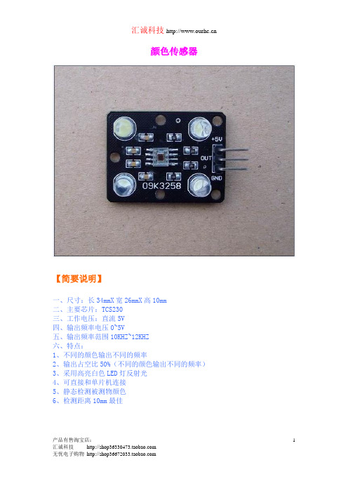
当TCS230识别颜色时,就用这3个参数对所测颜色的R、G和B进行调整。这里有两种方法来计算调整参数:1、依次选通三颜色的滤波器,然后对TCS230的输出脉冲依次进行计数。当计数到255时停止计数,分别计算每个通道所用的时间,这些时间对应于实际测试时TCS230每种滤波器所采用的时间基准,在这段时间内所测得的脉冲数就是所对应的R、G和B的值。2、设置定时器为一固定时间(例如10ms),然后选通三种颜色的滤波器,计算这段时间内TCS230的输出脉冲数,计算出一个比例因子,通过这个比例因子可以把这些脉冲数变为255。在实际测试时,室外同样的时间进行计数,把测得的脉冲数再乘以求得的比例因子,然后就可以得到所对应的R寸:长34mmX宽26mmX高10mm
二、主要芯片:TCS230
三、工作电压:直流5V
四、输出频率电压0~5V
五、特点:
1、所有的引脚全部引出
2、输出占空比50%
3、采用高亮白色LED灯反射光
4、可直接和单片机连接
GYJ-0102 TCS230颜色识别传感器 颜色比较 色差判定 提供例程 带透镜防干扰

【简要说明】序号Type ♦产品型号GYJ-01021.Appearance♦产品外形图参考图在下面2.Outline ♦外形尺寸长x宽x高34mmX 26mmX 10mm3.Important chips♦重要芯片TCS23004.power voltage ♦供电电压供电DC5V 信号DC5V5.Features♦主要特征所有的引脚全部引出采用高亮白色LED灯补光可直接和单片机连接2.54mm 管脚距排针静态检测被测物颜色检测距离5厘米以内抗干扰能力强提供原理图、尺寸图、例程6.Rating ♦参数7.Ambient Temperature ♦环境温度-30℃ to +70℃8.Ambient humidity♦环境湿度20% to 80%RH【标注图片】【工作电压和电流】(直流5V0.04A)【输出波形】【原理图】/** TCS3200模块* 用途:TCS3200颜色测试,读取RGB值,LCD1602显示R,G,B值//接线说明://模块S2-----单片机P1.1//模块S3-----单片机P1.0//模块OUT----单片机P3.5(计数器1输入)//模块VCC----单片机VCC//模块GND----单片机GND#include<REG52.H>#include<math.h> //Keil library#include<stdio.h> //Keil library#include<INTRINS.H>#define uchar unsigned char#define uint unsigned int#define DataPort P2 //LCD1602 数据端口sbit LCM_RS=P0^2; //LCD1602 控制端口sbit LCM_RW=P0^1; //LCD1602 控制端口sbit LCM_EN=P0^0; //LCD1602 控制端口/**引脚定义**/sbit s2=P1^1; //TCS3200 S2sbit s3=P1^0; //TCS3200 S3//TCS3200 S0 模块内部默认上拉//TCS3200 S1 模块内部默认上拉//TCS3200 OE 模块内部接地sbit test_pin=P1^2; //用示波器看这个引脚,可知道定时器中断频率//变量、常量定义uchar ge,shi,bai ;uchar rp=3,gp=3,bp=6; //定义比例因子,具体环境可以修改uchar count; //颜色标志位(0:红1:绿2:蓝)//显示数组uchar disp_R[3]; //红uchar disp_G[3]; //绿uchar disp_B[3]; //蓝//********定义函数***************************** void delay(unsigned int k);void InitLcd();void WriteDataLCM(uchar dataW);void WriteCommandLCM(uchar CMD,uchar Attribc); void DisplayOneChar(uchar X,uchar Y,uchar DData);//*********LCD1602初始化********************** void InitLcd(){WriteCommandLCM(0x38,1);WriteCommandLCM(0x08,1);WriteCommandLCM(0x01,1);WriteCommandLCM(0x06,1);WriteCommandLCM(0x0c,1);}//**********检测忙信号************************ void WaitForEnable(void){DataPort=0xff;LCM_RS=0;LCM_RW=1;_nop_();LCM_EN=1;_nop_();_nop_();while(DataPort&0x80);LCM_EN=0;}//**********写命令至LCD*********************** void WriteCommandLCM(uchar CMD,uchar Attribc){if(Attribc)WaitForEnable();LCM_RS=0;LCM_RW=0;_nop_();DataPort=CMD;_nop_();LCM_EN=1;_nop_();_nop_();LCM_EN=0;}//**********写数据至LCD************************ void WriteDataLCM(uchar dataW){WaitForEnable();LCM_RS=1;LCM_RW=0;_nop_();DataPort=dataW;_nop_();LCM_EN=1;_nop_();_nop_();LCM_EN=0;}//*********写一个字符数据到指定的目标***********void DisplayOneChar(uchar X,uchar Y,uchar DData) {Y&=1;X&=15;if(Y)X|=0x40;X|=0x80;WriteCommandLCM(X,0);WriteDataLCM(DData);}//**********延时函数***************void delay(unsigned int k){unsigned int i,j;for(i=0;i<k;i++){for(j=0;j<121;j++){;}}}/******************************************* * 函数名称: t0_init()* 函数功能: 定时器0初始化* 入口参数: 无* 出口参数: 无/********************************************/ void t0_init(){TMOD=0x51; //T1计数T0定时工作方式1TH1=0x00; //计数初值TL1=0x00;TH0=0xE0;TL0=0x00; //11。
基才颜色传感器TCS230的氯离子和PH检测仪设计

Z HANG B o,L U Ya o — c h e n g ,C HE N Xi a o ・ y a n, YO U L i — h u a
( S c h o o l o f Me c h a n i c a l E n g i n e e r i n g , J i a n g n n a U n i v e r s i t y ,Wu x i 2 1 4 1 2 2 , C h i n a )
TCS 颜色传感器中文资料
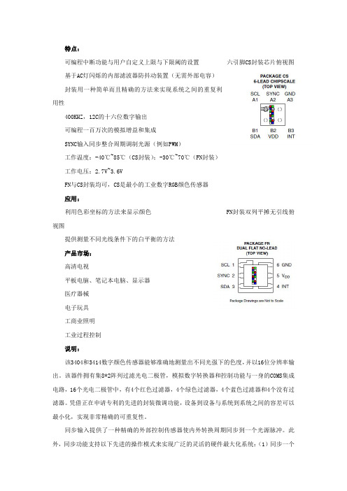
特点:可编程中断功能与用户自定义上限与下限阈的设置六引脚CS封装芯片俯视图基于AC灯闪烁的内部滤波器防抖动装置(无需外部电容)封装用一种简单而且精确的方法来实现系统之间的重复利用性400KHZ,12C的十六位数字输出可编程一百万次的模拟增益和集成SYNC输入同步整合周期调制光源(例如PWM)工作温度:-40℃~85℃(CS封装);-30℃~70℃(FN封装)工作电压:2.7V~3.6VFN与CS封装均可,CS是最小的工业数字RGB颜色传感器应用:利用色彩坐标的方法来显示颜色FN封装双列平摊无引线俯视图提供测量不同光线条件下的白平衡的方法产品市场:高清电视平板电脑、笔记本电脑、显示器医疗器械电子玩具工商业照明工业过程控制说明:该3404和3414数字颜色传感器能够准确地测量出不同光强下的色度,并以16位分辨率输出。
该器件拥有集8*2阵列过滤光电二极管,模拟数字转换器和控制功能与一身的COMS集成电路,16个光电二极管中,有4个红色过滤器,4个绿色过滤器,4个蓝色过滤器和4个没有过滤器。
凭借正在申请专利的先进的封装微调功能,设备到设备与系统到系统之间的容差可以最小化,实现非常精确的可重复性。
同步输入提供了一种精确的外部控制传感器使内外转换周期同步到一个光源脉冲。
此外,同步功能支持以下先进的操作模式来实现广泛的灵活的硬件最大化系统:(1)同步一个内部时间周期和(2)积累指定号码的脉冲。
该装置还支持自由运行和串行总线控制的一体化模式如果传感器在不需要光源的情况下能够精确地耦合。
四个平行的A/D转换器将光电二极管的电流用SMBus(TCS3404)或者I2C(TCS3414)转换为数字输出,送入微处理器。
RGB可以在一个读周期中读出以尽量减少在通信接口中定义的读取命令协议的数量。
这个装置的从机地址是39h(0111001b)。
一个SMB报警式中断(TCS3404)和一个传统的水平式中断(TCS3414)可以为四种高低阈设置渠道中的任意一种做动态配置,中断将保持到固件清除。
汽车传感器全集 中英文

1.转速传感器,用于检测和判定一(四)缸上止点。
2.凸轮轴位置传感器,用于区分一(四)缸压缩上止点。
3.位置传感器,用于检测发动机的位置(也是用于提供发动机负荷信号)。
4.,用于检测发动机是否发生爆震。
5.水温传感器,用于检测温度(提供发动机温度信号)。
6.进气温度传感器,用于检测进气温度。
7.绝对压力传感器,用于检测进气管内的进气压力。
8.,用于检测进气空气的质量。
9.加速踏板位置传感器,用于检测加速踏板位置。
10.轮速传感器,用于检测轮速。
11.车速传感器,用于检测车速。
此外还有、雨量传感器、传感器、车身高度传感器、燃油液位传感器、燃油温度传感器、、喷油器升程传感器等等。
国五基础传感器(基本必备的)曲轴传感器正时点(坏掉打火不着车各缸高压线无火/和点火线圈损坏一个状况)氧前传感器尾气踩点(配合节气门进气压力损坏油耗增高)氧后传感器三元监控(损坏三元状况不知道)节气门传感器油门监控(损坏油门迟钝油耗狂增远高于氧传感器损坏)进气压力传感器进气监控(损坏毛病不少怠速不稳热车时间不稳加油顿挫油耗高)水温传感器温度监控(损坏水温表不准过热保护没有或误报强制灭车电子调节器失效油耗不稳)?缩写、英文全称、中文A/C Air Conditioning 空调A /T Automatic Transaxle (Transmission) 自动变速器ACC Air Condition Clutch 空调离合器ACT Air Charge Temperature 进气温度AFC Air Flow control 空气流量控制AFS Air Flow Sensor 空气流量传感器AI Air Injection 二次空气喷射ACL AirCleaner 空气滤清器AIV Air Injection Valve 空气喷射阀ALCl Assembly Line Communication Link 总装线测试插座ALDl Assembly lne Diagnostic Link 总装线诊断插座ALT Alternator 交流发电机APS Absolute Pressure Sensor 绝对压力传感器ATS Air Temperature Sensor 空气温度传感器AP Accelerator Pedal 加速踏板ABS Anti-lock Brake System 防抱死刹车系统ATF Automatic Transmission Fluid 自动变速箱油液A/F Air Fuel Ratio 空气燃料混合比AMP Ampere(S) 安培( 电流强度)APPROX Approximately 大约,近似ATDC After Top Dead Center 上止点后AUTO Automatic 自动ATT Attachment 附件ALR Automatic Lock Return 自动馈回缩器B+ Battery Positive Voltage 蓄电池正极BARO Barometric Pressure 大气压力BARO Sensor Barometric Pressure Sensor 大气压力传感器BP Barometric Pressure Sensor 大气压力传感器BAT Battery 电瓶BTDC Before Top Dead Center 上死点前BDC Bottom Dead Center 下死点CMP Camshaft Position 凸轮轴位置CARB Carburetor 化油器CCC Converter Clutch Control 转换离合器控制CDI Capacitive Discharge Ignition 电容放电式点火CMFI Central Multiport Fuel lnjectoion 中央多点燃油喷射CES Clutch Engage Switch 离合器接合开关CFI Central Fuel lnjection 中央燃油喷射CFI Continous Fuel Injection 连续燃油喷射CID Cylinder Identification Sensor 汽缸传感器CIS Continous Fuel lnjection 连续燃油喷射CKP Crank shaft Position 曲轴位置CKP Sensor Crank shaft Position Sensor 曲轴位置传感器CL Closed Loop 闭环控制CP Crank shaft Position 曲轴位置CPP Clutch Pedal Position 离合器踏板位置CPS Camshaft Position Sensor 凸轮轴位置传感器CPS Crank shaft Position Sensor 曲轴位置传感器CTP Closed Throttle Position ,节气门关闭位置CTS Engine Coolant Temperature Sensor 发动机水温传感器CYP Cylinder Position 汽缸位置CAT Catalytic Converter 触酶转换器CO Carbon Monoxide 一氧化碳CYL Cylinder 汽缸CPC Clutch Pressure Control 离合器压力控制CARB Carburetor 汽化器,化油器CPU Central Processing Unit 中央处理器CHG Charge 充电D — Jetronic Multiport Fuel Injection D 型多点燃油喷射DLC Data Link Connector 数据传递插接器DFI Direct Fuel Injection 直接燃油喷射DI Direct lnjecton 直接喷射DI Distributor lgnition 分电器点火DID Direct lnjection — Diesel 柴油直接喷射DTM Diagnostic Test Mode 诊断测试模式DTC Diagnostic Trouble Code 诊断故障码DLI Distributorless Ignitioo 无分电器点火DS Detonation Sensor 爆震传感器DIFF Differential 差速器DOHC DoubleOverhe~IdCamshaft 顶置双凸轮轴DPI Dual Point lnjection 两点喷射DRL Daytime Running Light 白天行驶灯E2PROM Electrically Erasable Programmable Read Only Memory 可以擦写的只读存储器EATX Electronic Automatic Transmission/Transaxle 电控自动变速器EC Engine Control 发动机控制ECA Electronic Control Assembly 电子控制总成ECM Engine Control Module 发动机控制模块ECT Engine Coolant Temperature 发动机冷却水温EDIS Electronic Distributorless lgnition System 电子无分电器点火系统EEC Electronic Engine Control 电子发动机控制EEPROM Electrially Erasable Programmable Read Only Memory 可电擦写的只读存储器EFI Electronic Fuel lnjection 电控燃油喷射EGOS Exhaust Gas Oxygen Sensor 氧传感器EGR Exhaust Gas Recirculation 废气再循环EGRV ExhaustGasRecirculationvalve 废气再循环阀AEC 汽车排放控制英文全称:automobile emission controlAFV 代用燃料汽车英文全称:Alternative Fuel VehicleCHMSL (汽车)高位制动灯英文全称:Center High Mounted Stop Lamp 词条简介:汽车上第三高位制动灯具,通常由LED组成,红色GMLAN 通用汽车局域网英文全称:General Motors local area network 词条简介:汽车电子内部用网HID 汽车高压气体放电灯英文全称:High Intensity Discharge Lamp 词条简介:汽车高压气体放电灯是一种利用处于高压状态的气体放光的电灯。
颜色识别程序
1./*==========TCS230颜色识别传感器管脚说明===========================================2.引脚号符号功能说明3. 1 S0 输出频率分频系数选择输入端4. 2 S1 输出频率分频系数选择输入端5. 3 OE 输入频率使能端。
低电平有效6. 4 GND 电源地7. 5 VDD 电源电压8. 6 OUT 输出频率(fo)9. 7 S2 光电二极管类型选择输入端10. 8 S3 光电二极管类型选择输入端11.12.===============================程序接口========================================*/13./*----S0,S1输出频率分频比例选择----*/14./* S0 S1 输出频率分频比例 */15./* L L 掉电 0 */16./* L H 2% 1 */17./* H L 20% 2 */18./* H H 100% 3 *///硬件接口已经下拉19.20.21.//使能E低电平有效22.23./*------S2,S3光电二极管类型选择-----*/24./* S2 S3 光电二极管类型 */25./* L L 红色 0 */26./* L H 蓝色 1 */27./* H L 清除(无滤波器) 2 */28./* H H 绿色 3 */29./* PB6 PB7 */30./*==============================================================================*/31.32.#define uchar unsigned char33.#define uint unsigned int34.#include<util/delay.h>35.#define S2_S3_R {DDRB|=(1<<6);DDRB|=(1<<7); PORTB &=~(1<<6);PORTB &=~(1<<7);} //红色 red36.#define S2_S3_B {DDRB|=(1<<6);DDRB|=(1<<7); PORTB &=~(1<<6);PORTB |= (1<<7);} //蓝色 blue37.#define S2_S3_0 {DDRB|=(1<<6);DDRB|=(1<<7); PORTB |= (1<<6);PORTB &=~(1<<7);} //清除38.#define S2_S3_G {DDRB|=(1<<6);DDRB|=(1<<7); PORTB |= (1<<6);PORTB |= (1<<7);} //绿色 green39.40./*-----1602显示用到的字符串--------*/41.unsigned char data_[]="0123456789";42.uchar black[] ="黑色 ";43.uchar white[] ="白色 ";44.uchar red[] ="红色 ";45.uchar green[] ="绿色 ";46.uchar blue[] ="蓝色 ";47.48.49.uchar TCS230_count=0; //外部中断计数50.volatile uchar TCS230_flag=0; //RGB中断计数51.uchar count_rgb; //通道选择计数52.53.54.55./*---GB数值存储--*/56.uchar R_count=0;57.uchar G_count=0;58.uchar B_count=0;59.60./*****************************************************61. * 函数名:Init_TCS230(uchar way)62. * 功能:TCS230通道选择63. * 说明:0--R,3--G,1--B64. * 子函数:无65. * 变量:无66.******************************************************/67.void Init_TCS230(uchar way)68.{69./*switch(fre) //硬件接口已经下拉70. {71. case 0: {S0_S1_0; break;}72. case 1: {S0_S1_2; break;}73. case 2: {S0_S1_20; break;}74. case 3: {S0_S1_100; break;}75. }*/76.77.switch(way)78. {79.case 0: {S2_S3_R; break;} //红色通道80.case 1: {S2_S3_B; break;} //蓝色通道81.case 2: {S2_S3_0; break;} //清除通道82.case 3: {S2_S3_G; break;} //绿色通道83. }84.85. TCCR2 = 0x0F;//启动定时器86. GIFR |= (1<<INTF2);//清中断标志87. GICR |= 0x20; //开颜色中断88.}89.90.91.92./*****************************************************93. * 函数名:display(uchar i1,uchar i2,uchar i3,uchar a)94. * 功能:颜色RGB读取,1602显示95. * 说明:96. * 子函数:Displaychar_160297. * 变量:无98.******************************************************/99.void display(uchar i1,uchar i2,uchar i3,uchar a)100.{101. distwochar_12864(i1,0,data_[a/100],data_[a/10%10]);102. distwochar_12864(1,0,data_[a%10],' ');103.}104.105.//1602显示106./*107.{108. Displaychar(i1,0,data_[a/100]); //显示百位109. Displaychar(i2,0,data_[a/10%10]); //显示十位110. Displaychar(i3,0,data_[a%10]); //显示个位111.}*/112.113.114.115./********************************************************************* 116. * 函数名:find_colour(uchar r,uchar g,uchar b)117. * 功能:颜色识别显示118. * 说明:通过读取R\G\B判断是什么颜色119. * 子函数:Displaystr_1602120. * 变量:无121.*********************************************************************/ 122.void find_colour(uchar r,uchar g,uchar b)123.{124.if( ((r>3)&&(r<10)) && ((g>3)&&(g<20)) && ((b>5)&&(b<13)) )125. {126. dispstr_12864(0,1,black);127. }128.129.if( ((r>9)&&(r<20)) && ((g>22)&&(g<42)) && ((b>34)&&(b<65)) ) 130. {131. dispstr_12864(0,1,blue);132. }133.134.if( ((r>11)&&(r<23)) && ((g>26)&&(g<49)) && ((b>24)&&(b<46)) ) 135. {136. dispstr_12864(0,1,green);137. }138.139.if( ((r>20)&&(r<40)) && ((g>5)&&(g<13)) && ((b>5)&&(b<13)) ) 140. {141. dispstr_12864(0,1,red);142. }143.144.if( ((r>33)&&(r<63)) && ((g>42)&&(g<90)) && ((b>56)&&(b<103)) ) 145. {146. dispstr_12864(0,1,white);147. }148.149.if( ((r>8)&&(r<15)) && ((g>13)&&(g<24)) && ((b>11)&&(b<20)) ) 150. {151. dispstr_12864(0,1,"深绿色");152. }153.154.if( ((r>8)&&(r<14)) && ((g>11)&&(g<22)) && ((b>26)&&(b<49)) ) 155. {156. dispstr_12864(0,1,"深蓝色");157. }158.159.if( ((r>18)&&(r<34)) && ((g>18)&&(g<33)) && ((b>12)&&(b<23)) ) 160. {161. dispstr_12864(0,1,"橙色 ");162. }163.}164.165.166./************************************************************** 167. * 函数名:TCS230_task(void)V168. * 功能:TCS230颜色处理169. * 说明:分别读取不同颜色的RGB值,判断显示颜色及其RGB数值170. * 子函数:find_colour,Init_TCS230171. * 变量:无172.**************************************************************/173.void TCS230_task(void)174.{175.176.for(count_rgb=0;count_rgb<3;) //读三个通道的值但因为不是连续的读177. {178. Init_TCS230(0);//选择R通道179.while(TCS230_flag==0) //等待读数180. {181.//1602显示函数182.//display(0,1,2,R_count);183.//display(5,6,7,G_count);184.//display(10,11,12,B_count);185. distwochar_12864(0,0,data_[R_count/100],data_[R_count/10%10]);186. distwochar_12864(1,0,data_[R_count%10],' ');187.188. distwochar_12864(2,0,data_[G_count/100],data_[G_count/10%10]);189. distwochar_12864(3,0,data_[G_count%10],' ');190.191. distwochar_12864(4,0,data_[B_count/100],data_[B_count/10%10]);192. distwochar_12864(5,0,data_[B_count%10],' ');193.194.195. find_colour(R_count,G_count,B_count); //对颜色进行判断并显示196.197. }198.199.if(TCS230_flag==1) //读取R通道数据200. {201. R_count=TCS230_count; //读取R值202. distwochar_12864(0,0,data_[R_count/100],data_[R_count/10%10]);/ /更新显示R值203. distwochar_12864(1,0,data_[R_count%10],' ');204. find_colour(R_count,G_count,B_count);//颜色判断205. TCS230_flag=1;206. TCS230_count=0; //清零207. TCNT2 = 0x00;//重新给T2初始值208. Init_TCS230(3);//G通道选择209. count_rgb++; //通道计数++210. }211.212.while(TCS230_flag==1) //等待读取G值213. {214.//display(0,1,2,R_count);215.//display(5,6,7,G_count);216.//display(10,11,12,B_count);217. distwochar_12864(0,0,data_[R_count/100],data_[R_count/10%10]);218. distwochar_12864(1,0,data_[R_count%10],' ');219.220. distwochar_12864(2,0,data_[G_count/100],data_[G_count/10%10]);221. distwochar_12864(3,0,data_[G_count%10],' ');222.223. distwochar_12864(4,0,data_[B_count/100],data_[B_count/10%10]);224. distwochar_12864(5,0,data_[B_count%10],' ');225.226. find_colour(R_count,G_count,B_count);//颜色识别显示227. }228.229.230.if(TCS230_flag==2)231. {232. G_count=TCS230_count; //读取G值233.234. distwochar_12864(2,0,data_[G_count/100],data_[G_count/10%10]);235. distwochar_12864(3,0,data_[G_count%10],' ');236.237. find_colour(R_count,G_count,B_count);238. TCS230_flag=2;239. TCS230_count=0; //清零240. TCNT2 = 0x00; //T2初始值241. Init_TCS230(1); //B通道选择242. count_rgb++;243. }244.245.while(TCS230_flag==2)246. {247.248. distwochar_12864(0,0,data_[R_count/100],data_[R_count/10%10]);249. distwochar_12864(1,0,data_[R_count%10],' ');250.251. distwochar_12864(2,0,data_[G_count/100],data_[G_count/10%10]);252. distwochar_12864(3,0,data_[G_count%10],' ');253.254. distwochar_12864(4,0,data_[B_count/100],data_[B_count/10%10]);255. distwochar_12864(5,0,data_[B_count%10],' ');256.257. find_colour(R_count,G_count,B_count);//颜色识别显示258. _delay_ms(1);259. }260.261.if(TCS230_flag==3)262. {263. B_count=TCS230_count; //读取B值264.265. distwochar_12864(4,0,data_[B_count/100],data_[B_count/10%10]);266. distwochar_12864(5,0,data_[B_count%10],' ');267.268. find_colour(R_count,G_count,B_count);269. TCS230_flag=0;270. TCS230_count=0;271. count_rgb++;272. }273. }274.275. find_colour(R_count,G_count,B_count); //颜色识别显示276.}。
- 1、下载文档前请自行甄别文档内容的完整性,平台不提供额外的编辑、内容补充、找答案等附加服务。
- 2、"仅部分预览"的文档,不可在线预览部分如存在完整性等问题,可反馈申请退款(可完整预览的文档不适用该条件!)。
- 3、如文档侵犯您的权益,请联系客服反馈,我们会尽快为您处理(人工客服工作时间:9:00-18:30)。
基于TAOS公司的TCS230的颜色感应TAOS公司的TCS230是一个小的、高度集成、8引脚、SOIC封装的色彩传感装置。
它以模拟频率的方式输出短波(蓝色)、中波(绿色)、长波(红色)、宽带(白)光功率的事件数量。
它可用于各种色彩感应应用领域。
该设备的详细资料中可以找到它的数据表。
我们将使用一个光学刺激方案的ColorChecker图表工作,通过检测的色彩数值例子。
下图,在图1所示,是由GretagMacbeth生产和分配。
图表长约13英寸,9英寸(330毫米×230毫米),它包含了64阵列安排24色斑。
到5背面图2显示了在图表的每一行四个补丁的光谱反射-即入射光被反射的那部分(相对于一个理想的漫反射)作为波长从350功能,纳米到750纳米。
图1 ColorChecker色补丁包含18个和6步灰色系列图2 ColorChecker谱,第一行图3 ColorChecker谱,第二排图4 ColorChecker光谱,第三行图5 ColorChecker谱,底排(中性系列)图6锥锥光感受器敏感性所示。
短波敏感的感光细胞远远低于其他两种类型的敏感。
中波和长波的感光细胞的反应有很大的重叠。
视觉是不敏感,准确的刺激波长:什么是光功率下atters每个响应曲线综合。
1. 色觉简介所谓感光细胞在视网膜视锥细胞是人类色彩视觉负责。
内有电磁频谱三种类型的视锥细胞,敏感的长波,中波,短波辐射及约400纳米之间和700纳米。
由于锥敏感性在频谱的部分出现红色,绿色和蓝色的很粗糙,色彩科学家记为ρ,γ,以及希腊字母为R,G细胞的类型,和b (为了表示对传感器的R,G,和B将错误建议更密切的对应关系。
)的圆锥体的谱反应的估计是在上面绘制图6。
在物理世界的光,其特征是光谱功率分布(结构化产品说明)。
彩色对象,其特征是反射光谱曲线,如在的ColorChecker的。
然而,视觉不敏感,对刺激精确波长:根据现代色彩科学理论,最重要的事情是在每个响应曲线光功率积分。
这恰有三种视锥细胞类型导致trichromaticity财产:三个组成部分是必要的和足够的特征颜色。
有些人可能会用“感觉到的颜色的眼睛,“但我了CON - Sider 的限定词是多余的,充其量,误导在最坏的情况:色彩是由视觉定义,所以没有必要使用合格的短语“因为感觉到的眼睛,“或使用的形容词时可见指颜色。
2. 色彩检查如何光谱与颜色相关的知识装备,绘制色度坐标,对照明色彩的依赖,我们可以返回的ColorChecker。
GretagMac- Beth没公布或保证的ColorChecker补丁的光谱成分。
然而,标称Cie的[的X,Y和Z]值被公布。
在底行的ColorChecker 补丁包含中性色,在图5中的神话传说中的数字符号反映十分之一的亮度(长*)值的这些补丁。
光谱绘制2和第3页上表示物理波长由波长的反射率的补丁。
这些光谱反射已测色仪测量tances称为分光光度计。
如果你有机会访问光源具有完全的权力分配,甚至在整个可见光谱,反射率曲线则绘制在这里可以简单地扩展到repre,发送应用程序中的反射率。
实践没有光源的光谱分布十分均匀,因此补偿neces-萨利:你必须计算与图表的光谱反射的光源的波长社民党按波长的产品。
我们将首先从图表计算在CIE[的X,Y和Z]值。
(这些值应同意Gretag提供的数字。
)然后我们将计算[的R,G,B]的,将由一TCS230检测值。
为了计算Cie公司[的X,Y和Z],我们把31 ×3矩阵代表职能的配色在CIE标准观察者(CMFs),并执行一个有31个光谱响应矩阵产品价值为照明纠正。
这将产生的[x,Y,Z轴]三刺激值。
当色度坐标,通过投影[的x,y]是来自[的X,Y和Z]变换计算公式1,然后绘制,结果如图9色度图。
马蹄状的人物,在底部封闭,包含所有的颜色:每个非负的光谱分布产生[的x,y]对本地区范围内的阴谋。
拥有轻成荫的三角显示包含所有的地区,可以通过一个附加的RGB 使用的sRGB系统(建议709)原色产生颜色。
这个地区typifies视频和桌面计算(的sRGB)。
这些点绘制在图9是本的ColorChecker的颜色。
白色和灰色值都聚集在附近的图表的中心。
图9 ColorChecker补丁坐标上绘制在CIE是[的x,y]色度图。
马蹄形包围了所有的颜色;包围的三角形代表可以在视频(建议709)和桌面计算(的sRGB)的颜色。
3. TCS230图10显示了TCS230的四个通道的反应。
黑色曲线显示了未经过滤的传感器元件的响应。
红色,绿色和蓝色的曲线显示了长波敏感,中波敏感,短波敏感元素分别响应。
正如我在第5页提到,色觉Cie的模型,包含集成光栅一个在X(λ)和Y (λ)和z(λ)配色函数行动(图7制成图表)社民党,生产X,Y和Z值。
要使用TCS230彩色估计我们执行了一个类似的计算,但使用而不是在CIE CMFsTCS230灵敏度函数:我们整合下TCS230的灵敏度曲线社民党,生产的R,G 和B值。
该设备的R,G和B值将取决于几个因素:光源,样品的光谱反射光谱的内容,任何干预光学元件的光谱衰减(如镜头),最后的光谱响应职能TCS230。
各种光谱现象为蓝本,通过计算波长的波长的产品。
图10 TCS230光谱灵敏度绘制在这里。
红色,绿色和蓝色通道都绘制在相应的颜色;灰线反映了清除(未过滤)通道的灵敏度。
由于这些反应是从CIE标准观察者的不同,所报告的值TCS230没有色度。
然而,适当的信号处理产生足够的颜色信息,对于许多工业应用准确。
由于事实TCS230是敏感的红外光(波长有700纳米以上),而事实上,大多数光源产生的红外线地区电力,典型应用包括一个红外截止在TCS230前过滤器。
背面图11显示了一个典型的红外滤光片的反应。
继续我们的的ColorChecker造型,与我们照亮了CIE D65光源的的ColorChecker,整合下的TCS230反射光谱敏感曲线产生,并最终转化为Cie的[的x,y]坐标。
相对亮度值,通过这个过程获得相当准确的,然而,染色体maticity 坐标不是很准确。
图12的裸图的R,G和B值在CIE色度。
结果从不同的ColorChecker坐标图9绘制。
对于分歧的原因是TCS230的灵敏度函数系统蒸发散不同于匹配功能,是适当的sRGB色彩了相当大。
即使TCS230敏感性均符合的sRGB,在该光源的光谱功率分布和干预光学康波- nents会导致一些分歧谱的影响效果接近达成协议。
要形成一个色彩更准确地估计需要处理的原始TCS230的R,G,B值并通过线性3 ×3矩阵的系数cients是相对于该光源,光学元件的干预光谱响应谱优化,和响应曲线的TCS230。
数据处理操作可以被表示为矩阵形式如下:x=M•t 公式2 符号T表示一个三个元素的载体的设备价值从色块抓获。
M代表3 ×3色校正矩阵,我们将适用于这些价值观通过矩阵乘法,由•符号表示。
符号X表示估计[的X,Y和Z]值结果向量。
我们可以利用矩阵符号来象征加工三个色块安排一次设置成一个3×3矩阵吨连续的T行连续列值的设备三套,包含红色,绿色和蓝色数据分别。
经M矩阵乘法,所产生的矩阵X的列包含XYZ值的连续采样; X的行包含X,Y和Z 值分别tively。
一个方程表达了三个补丁一次映射:X=M•T 公式3 给定一个矩阵T的列包含三种器件样品集,并包含一个矩阵X某某三元三组对应的理想,有一种独特的矩阵M,从T到X的映射是通过计算逆矩阵的T,然后用X矩阵计算产品(由预乘):M=X • 公式4由此产生的 3 ×3色校正矩阵M的每一个选择三个值集的设备的Tris- timulus值对应设置准确的地图。
这是没有必要在反矩阵传感时间!矩阵M可以事先计算,依据的预期将提交拟申请在传感器的样品。
要处理三对检测样品元件值,所有这些都是必要的,是对矩阵乘积的计算公式3。
一个色彩校正矩阵,产生在超过三个样本良好的效果,可以通过数值计算优化过程。
当这样做,没有特别的样品可能正好映射到理想三原色集,但一个线性矩阵可以构造,尽量减少跨样本范围(其中的错误是在最小二乘意义上衡量)的错误。
色彩校正行动仍在完成公式2完全一样。
Sensing color with the TAOS TCS230The TAOS TCS230 is a small, highly integrated color sensing device packaged in a clear plastic 8-pin SOIC. It reports, as analog frequency, the amount of shortwave (blue), mediumwave (green), longwave (red), and wideband (white) optical power incident onto the device. It can be used in a variety of color sensing applications. Details of the device can be found in its datasheet.We will use the ColorChecker chart as an optical stimulus to work through a numerical example of color sensing. The chart, depicted in Figure 1, is manufactured and distributed by GretagMacbeth. The chart measures approximately 13 inches by 9 inches (330 mm by 230 mm); it contains 24 colored patches arranged in a 6 by 4 array. Figures 2 through 5 overleaf show the spectral reflectance of the patches in each of the four rows of the chart – that is, the fraction of incident light that is reflected (with respect to an ideal diffuse reflector), as a function of wavelength from 350 nm to 750 nm.Figure 1 The ColorChecker contains 18 colored patches and a 6-step gray series.Figure 2 ColorChecker spectra, top row.Figure 3 ColorChecker spectra, second row.Figure 4 ColorChecker spectra, third row. Figure 5 ColorChecker spectra, bottom row (neutral series)Figure 6 Cone sensitivities of cone photoreceptors are shown. The shortwave-sensitive photoreceptors are much less sensitive than the other two types. The responses of the mediumwave and longwave photoreceptors have a great deal of overlap. Vision is not sensitive to the precise wavelength of the stimulus: What atters is optical power integrated under each response curve.1. Introduction to color visionPhotoreceptor cells called cones in the retina are responsible for human color vision. There are three types of cone cells, sensitive to longwave, mediumwave, and shortwave radiation within the electro-magnetic spectrum between about 400 nm and 700 nm. Because the cone sensitivities are very roughly in the parts of the spectrum that appear red, gre en, and blue, color scientists denote the cell types as ρ,γ, and , the Greek letters for r, g, and b. (To denote the sensors R, G, and B would wrongly suggest a closer correspondence.) Estimates of the spectral response of the cone types are graphed in Figure 6 above.Light in the physical world can be characterized by spectral power distributions (SPDs). Colored objects can be characterized by spectral reflectance curves, such as those of the ColorChecker. However, vision is insensitive to the exact wavelength of a stimulus: According to the modern theory of color science, all that matters is the integral of optical power underneath each response curve. That there are exactly three types of cone cells leads to the property of trichromaticity: Three components are necessary and sufficient to characterize color. Some people might use the phrase “color as sensed by the eye,” but I con-sider that qualifier to be redundant at best, and misleading at worst: Color is defined by vision, so there is no need to use the qualifying phrase “as sensed by the eye,”or to use the adjective visible whenreferring to color.2. The Color CheckerEquipped with knowledge of how spectra are related to colors, the plotting of chromaticity coordinates, and the dependence of colors upon illumination, we can return to the ColorChecker. GretagMac-beth doesn’t publish or guarantee the spectral composition of the patches of the ColorChecker. However, nominal CIE [X, Y, Z] values are published. The patches in the bottom row of the ColorChecker contain neutral colors; the numeric notations in the legends of Figure 5 reflect one tenth of the lightness (L*) values of those patches.The spectra graphed on pages 2 and 3 represent the physical wave-length-by-wavelength reflectance of the patches. These spectral reflec-tances have been measured by color measurement instrument called a spectrophotometer. If you had access to a light source having perfectly even distribution of power across the visible spectrum, then the reflectance curves graphed here could simply be scaled to repre-sent the reflectance in your application. Practical light sources do not have perfectly even spectral distributions, so compensation is neces-sary: You must compute the wavelength-by-wavelength product of the illuminant’s SPD with the spectral reflectance of the chart.We will first calculate the CIE [X, Y, Z] values from the chart. (These values should agree with the figures provided by Gretag.) Then we will calculate the [R, G, B] values that will be detected by a TCS230.To calculate CIE [X, Y, Z], we take the 31×3 matrix representing the color matching functions (CMFs) of the CIE Standard Observer, and perform a matrix product with 31 spectral response values as corrected for illumination. This produces the [X, Y, Z] tristimulus values. When chromaticity coordinates [x, y] are computed from [X, Y, Z] through the projective transform in Equation 1, then plotted, the chromaticity diagram in Figure 9 results. The horseshoe-shaped figure, closed at the bottom, contains all colors: Every non-negative spectral distribution produces an [x, y] pair that plots within this region. The lightly-shaded triangle shows the region containing all colors that can be produced by an additive RGB system using sRGB (Rec. 709) primary colors. This region typifies video and desktop computing (sRGB). The points plotted in Figure 9 are the colors of the ColorChecker. White and gray values are clustered near the center of the chart.Figure 9 Coordinates of ColorChecker patches are graphed on the CIE [x, y] chromaticity diagram. The horseshoe encloses all colors; the triangle encloses the colors that can be represented in video (Rec. 709) and in desktop computing (sRGB).3. The TCS230Figure 10 shows the responses of the four channels of the TCS230. The black curve shows the response of the unfiltered sensor elements. The red, green, and blue curves show the responses of the longwave-sensitive, mediumwave-sensitive, and shortwave-sensitive elements respectively.As I mentioned on page 5, the CIE model of color vision involves inte-grating an SPD under the X(λ), Y(λ), and Z(λ) color matching func-tions (graphed in Figure 7), producing X, Y, and Z values. To use the TCS230 to estimate color we perform an analogous calculation, but using the TCS230 sensitivity functions instead of the CIE CMFs: We integrate the SPD under the TCS230’s sensitivity curves, and produce R, G, and B values. The device R, G, and B values will depend upon several factors: the spectral content of the illuminant, the spectral reflectance of the sample, the spectral attenuation of any intervening optical components (such as the lens), and finally, the spectral response functions of the TCS230. The various spectral phenomena are modelled by computing wavelength-by-wavelength products.Figure 10 TCS230 spectral sensitivities are graphed here. The red, green, and blue channels are graphed in the corresponding colors; the gray line reflects the sensitivity of the clear (unfiltered) channel. Because these responses are different from the CIE standard observer, the values reported by the TCS230 are not colorimetric. However, suitable signal processing yields color information that is sufficiently accurate for many industrial applications.Owing to the fact that the TCS230 is sensitive to infrared light (having wavelengths above 700 nm), and the fact that most light sources produce power in the infrared region, typical applications include an IR cut filter in front of the TCS230. Figure 11 overleaf shows the response of a typical IR cut filter.To form a more accurate estimate of color requires processing the raw TCS230 R, G, and B values through a linear 3×3 matrix whose coeffi-cients are optimized with respect to the spectrum of the illuminant, the spectral response of intervening optical components, and the response curves of the TCS230. The data processing operation can be represented in matrix form as follows:x=M•t Eq 2 The symbol t represents a three-element vector containing the device values captured from a color patch. M represents the 3×3 color correction matrix that we will apply to these values through matrix multiplication, denoted by the • symbol. The symbol x represents the resulting vector of estimated [X, Y, Z] values.We can use matrix notation to symbolize processing a set of three color patches at once, by arranging the three sets of device values into successive columns of a 3×3 matrix T. Successive rows of T contain red, green, and blue data respectively. Upon matrix multiplication by M, the columns of the resulting matrix X contain XYZvalues of the successive samples; the rows of X contain X, Y, and Z values respec-tively. One equation expresses the mapping of three patches at once: X=M•T Eq 3 Given a matrix T whose columns contain three sets of device samples, and a matrix X containing the corresponding set of three ideal XYZ triples, there is a unique matrix M that maps from T to X. It is found by computing the matrix inverse of T, then computing the matrix product (by premultiplication) with X:M=X • Eq 4The resulting 3×3 color correction matrix M exactly maps the each of the chosen three sets of device values to the corresponding set of tris-timulus values. It is not necessary to invert matrices at the time of sensing! The matrix M can be computed in advance, based upon the samples that are expected to be presented to the sensor in the intended application. To process three device values upon sensing a sample, all that is necessary is computation of the matrix product of Equation 3.A color correction matrix that produces good results across more than three samples can be computed through a numerical optimization procedure. When this is done, no particular sample is likely to map exactly to its ideal tristimulus set, but a linear matrix can be constructed that minimizes the error across a range of samples (where the error is measured in a least-squares sense). The color correction operation is still accomplished exactly as in Equation 2.。