传感器技术论文中英文对照资料外文翻译文献
红外传感器论文中英文资料对照外文翻译
中英文资料对照外文翻译外文资料Moving Object Counting with an Infrared Sensor NetworkBy KI, Chi KeungAbstractWireless Sensor Network (WSN) has become a hot research topic recently. Great benefit can be gained through the deployment of the WSN over a wide range of applications, covering the domains of commercial, military as well as residential. In this project, we design a counting system which tracks people who pass through a detecting zone as well as the corresponding moving directions. Such a system can be deployed in traffic control, resource management, and human flow control. Our design is based on our self-made cost-effective Infrared Sensing Module board which co-operates with a WSN. The design of our system includes Infrared Sensing Module design, sensor clustering, node communication, system architecture and deployment. We conduct a series of experiments to evaluate the system performance which demonstrates the efficiency of our Moving Object Counting system.Keywords:Infrared radiation,Wireless Sensor Node1.1 Introduction to InfraredInfrared radiation is a part of the electromagnetic radiation with a wavelength lying between visible light and radio waves. Infrared have be widely used nowadays including data communications, night vision, object tracking and so on. People commonly use infrared in data communication, since it is easily generated and only suffers little from electromagnetic interference. Take the TV remote control as an example, which can be found in everyone's home. The infrared remote control systems use infrared light-emitting diodes (LEDs) to send out an IR (infrared) signal when the button is pushed. A different pattern of pulses indicates the corresponding button being pushed. To allow the control of multiple appliances such as a TV, VCR, and cable box, without interference, systems generally have a preamble and an address to synchronize the receiver and identify the source and location of the infrared signal. To encode the data, systems generally vary the width of the pulses (pulse-width modulation) or the width of the spaces between the pulses (pulse space modulation). Another popular system, bi-phase encoding, uses signal transitions to convey information. Each pulse is actually a burst of IR at the carrier frequency. A 'high' means a burst of IR energy at the carrier frequency and a 'low' represents an absence of IR energy. There is no encoding standard. However, while a great many home entertainment devices use their own proprietary encoding schemes, somequasi-standards do exist. These include RC-5, RC-6, and REC-80. In addition, many manufacturers, such as NEC, have also established their own standards.Wireless Sensor Network (WSN) has become a hot research topic recently. Great benefit can be gained through the deployment of the WSN over a wide range of applications, covering the domains of commercial, military as well as residential. In this project, we design a counting system which tracks people who pass through a detecting zone as well as the corresponding moving directions. Such a system can be deployed in traffic control, resource management, and human flow control. Our design is based on our self-made cost-effective Infrared Sensing Module board which co-operates with a WSN. The design of our system includes Infrared Sensing Module design, sensor clustering, node communication, system architecture and deployment. We conduct a series of experiments to evaluate the system performance which demonstrates the efficiency of our Moving Object Counting system.1.2 Wireless sensor networkWireless sensor network (WSN) is a wireless network which consists of a vast number of autonomous sensor nodes using sensors to monitor physical or environmental conditions, such as temperature, acoustics, vibration, pressure, motion or pollutants, at different locations. Each node in a sensor network is typically equipped with a wireless communications device, a small microcontroller, one or more sensors, and an energy source, usually a battery. The size of a single sensor node can be as large as a shoebox and can be as small as the size of a grain of dust, depending on different applications. The cost of sensor nodes is similarly variable, ranging from hundreds of dollars to a few cents, depending on the size of the sensor network and the complexity requirement of the individual sensor nodes. The size and cost are constrained by sensor nodes, therefore, have result in corresponding limitations on available inputs such as energy, memory, computational speed and bandwidth. The development of wireless sensor networks (WSN) was originally motivated by military applications such as battlefield surveillance. Due to the advancement in micro-electronic mechanical system technology (MEMS), embedded microprocessors, and wireless networking, the WSN can be benefited in many civilian application areas, including habitat monitoring, healthcare applications, and home automation.1.3 Types of Wireless Sensor NetworksWireless sensor network nodes are typically less complex than general-purpose operating systems both because of the special requirements of sensor network applications and the resource constraints in sensor network hardware platforms. The operating system does not need to include support for user interfaces. Furthermore, the resource constraints in terms of memory and memory mapping hardware support make mechanisms such as virtual memory either unnecessary or impossible to implement. TinyOS [TinyOS] is possibly the first operating system specifically designed for wireless sensor networks. Unlike most other operating systems, TinyOS is based on an event-driven programming model instead of multithreading. TinyOS programs are composed into event handlers and tasks with run to completion-semantics. When an external event occurs, such as an incomingdata packet or a sensor reading, TinyOS calls the appropriate event handler to handle the event. The TinyOS system and programs are both written in a special programming language called nesC [nesC] which is an extension to the C programming language. NesC is designed to detect race conditions between tasks and event handlers. There are also operating systems that allow programming in C. Examples of such operating systems include Contiki [Contiki], and MANTIS. Contiki is designed to support loading modules over the network and supports run-time loading of standard ELF files. The Contiki kernel is event-driven, like TinyOS, but the system supports multithreading on a per-application basis. Unlike the event-driven Contiki kernel, the MANTIS kernel is based on preemptive multithreading. With preemptive multithreading, applications do not need to explicitly yield the microprocessor to other processes.1.4 Introduction to Wireless Sensor NodeA sensor node, also known as a mote, is a node in a wireless sensor network that is capable of performing processing, gathering sensory information and communicating with other connected nodes in the network. Sensor node should be in small size, consuming extremely low energy, autonomous and operate unattended, and adaptive to the environment. As wireless sensor nodes are micro-electronic sensor device, they can only be equipped with a limited power source. The main components of a sensor node include sensors, microcontroller, transceiver, and power source. Sensors are hardware devices that can produce measurable response to a change in a physical condition such as light density and sound density. The continuous analog signal collected by the sensors is digitized by Analog-to-Digital converter. The digitized signal is then passed to controllers for further processing. Most of the theoretical work on WSNs considers Passive and Omni directional sensors. Passive and Omni directional sensors sense the data without actually manipulating the environmen t with active probing, while no notion of “direction” involved in these measurements. Commonly people deploy sensor for detecting heat (e.g. thermal sensor), light (e.g. infrared sensor), ultra sound (e.g. ultrasonic sensor), or electromagnetism (e.g. magnetic sensor). In practice, a sensor node can equip with more than one sensor. Microcontroller performs tasks, processes data and controls the operations of other components in the sensor node. The sensor node is responsible for the signal processing upon the detection of the physical events as needed or on demand. It handles the interruption from the transceiver. In addition, it deals with the internal behavior, such as application-specific computation.The function of both transmitter and receiver are combined into a single device know as transceivers that are used in sensor nodes. Transceivers allow a sensor node to exchange information between the neighboring sensors and the sink node (a central receiver). The operational states of a transceiver are Transmit, Receive, Idle and Sleep. Power is stored either in the batteries or the capacitors. Batteries are the main source of power supply for the sensor nodes. Two types of batteries used are chargeable and non-rechargeable. They are also classified according to electrochemical material used for electrode such as NiCd(nickel-cadmium), NiZn(nickel-zinc), Nimh(nickel metal hydride), and Lithium-Ion. Current sensors are developed which are able to renewtheir energy from solar to vibration energy. Two major power saving policies used are Dynamic Power Management (DPM) and Dynamic V oltage Scaling (DVS). DPM takes care of shutting down parts of sensor node which are not currently used or active. DVS scheme varies the power levels depending on the non-deterministic workload. By varying the voltage along with the frequency, it is possible to obtain quadratic reduction in power consumption.1.5 ChallengesThe major challenges in the design and implementation of the wireless sensor network are mainly the energy limitation, hardware limitation and the area of coverage. Energy is the scarcest resource of WSN nodes, and it determines the lifetime of WSNs. WSNs are meant to be deployed in large numbers in various environments, including remote and hostile regions, with ad-hoc communications as key. For this reason, algorithms and protocols need to be lifetime maximization, robustness and fault tolerance and self-configuration. The challenge in hardware is to produce low cost and tiny sensor nodes. With respect to these objectives, current sensor nodes usually have limited computational capability and memory space. Consequently, the application software and algorithms in WSN should be well-optimized and condensed. In order to maximize the coverage area with a high stability and robustness of each signal node, multi-hop communication with low power consumption is preferred. Furthermore, to deal with the large network size, the designed protocol for a large scale WSN must be distributed.1.6 Research IssuesResearchers are interested in various areas of wireless sensor network, which include the design, implementation, and operation. These include hardware, software and middleware, which means primitives between the software and the hardware. As the WSNs are generally deployed in the resources-constrained environments with battery operated node, the researchers are mainly focus on the issues of energy optimization, coverage areas improvement, errors reduction, sensor network application, data security, sensor node mobility, and data packet routing algorithm among the sensors. In literature, a large group of researchers devoted a great amount of effort in the WSN. They focused in various areas, including physical property, sensor training, security through intelligent node cooperation, medium access, sensor coverage with random and deterministic placement, object locating and tracking, sensor location determination, addressing, energy efficient broadcasting and active scheduling, energy conserved routing, connectivity, data dissemination and gathering, sensor centric quality of routing, topology control and maintenance, etc.中文译文移动目标点数与红外传感器网络作者KI, Chi Keung摘要无线传感器网络(WSN)已成为最近的一个研究热点。
传感器技术论文中英文对照资料外文翻译文献
传感器技术论文中英文对照资料外文翻译文献Development of New Sensor TechnologiesSensors are devices that can convert physical。
chemical。
logical quantities。
etc。
into electrical signals。
The output signals can take different forms。
such as voltage。
current。
frequency。
pulse。
etc。
and can meet the requirements of n n。
processing。
recording。
display。
and control。
They are indispensable components in automatic n systems and automatic control systems。
If computers are compared to brains。
then sensors are like the five senses。
Sensors can correctly sense the measured quantity and convert it into a corresponding output。
playing a decisive role in the quality of the system。
The higher the degree of n。
the higher the requirements for sensors。
In today's n age。
the n industry includes three parts: sensing technology。
n technology。
and computer technology。
湿度传感器系统中英文对照外文翻译文献
中英文资料外文翻译文献英文:The right design for a relative humidity sensor systemOptimizing the response characteristics and accuracy of a humidity sensor system1 OverviewTo make the right choice when selecting a relative humidity sensor for an application, it is important to know and to be able to judge the deciding factors. In addition to long-term stability, which is a measure on how much a sensor changes its properties over time, these factors also include the measurement accuracy and the response characteristics of the sensor. Capacitive humidity sensors are based on the principle that a humidity-sensitive polymer absorbs or releases moisture as a function of the relative ambient humidity. Because this method is only a spot measurement at the sensor location, and usually the humidity of the surroundings is the desired quantity, the sensor must be brought into moisture equilibrium with the surroundings to obtain a precise measurement value. This process is realized by various transport phenomena (cf. the section titled "The housing effect on the response time"), which exhibit a time constant. Accuracy and response time are thus closely dependent on each other, and the design of a humidity measurement system becomes a challenge.2Measurement accuracyThe term measurement accuracy of a humidity sensor is understood primarily to refer to the deviation of the value measured by the sensor from the actual humidity. To determine the measurement accuracy, references, such as chilled mirror hygrometers, whose own tolerance must be taken into account, are used. In addition to this trivial component, humidity sensors require a given time for reaching stable humidity and temperature equilibrium (the humidity is a function of temperature and decreases with increasing temperature; a difference between sensor and ambient temperature leads to measurement errors). This response time thus has a significant effect on the value measured by the sensor and thus on the determinedaccuracy.This time-dependent characteristic is explained in more detail in the following.3Response characteristics and response timeThe response characteristics are defined by various parameters. These are:●The actual response characteristics of the humidity sensor at constant temperature.(1) How quickly the sensitive polymer absorbs or releases moisture until equilibrium is reached (intrinsic response time)(2) How fast the entire system reaches humidity equilibrium (housing effect)●The thermal response characteristics of the humidity sensor at a non-constant temperature(3) The thermal mass of the sensor(4) The system's thermal mass, which is thermally coupled to the sensor (e.g. printed circuit board)(5) Heat sources in the direct surroundings of the sensor (electronic components)(1) and (3) are determined entirely by the sensor itself, (1) primarily by the characteristics of the sensitive polymer.(2) and (4) are primarily determined by the construction of the entire system (shape and size of housing andreadout circuitry).(5) is determined by heat-emitting electronic components.These points will be discussed in more detail in the following.The intrinsic response time (1)Qualitatively, the response characteristics of capacitive humidity sensors look like the following (Fig. 1).Fig. 1: Typical and idealized response characteristics of capacitive humidity sensors (schematic)Because these response characteristics are especially pronounced at high humidity values, an isothermal humidity jump from 40% to 100% was selected here for illustration. The desired ideal behavior of the sensor is indicated in blue. In practice, however, the sensor behaves according to the red line, approximately according to:RH-t=(E-S)*(1-e)+S(t)Here, the time span 1 is usually very short (typ. 1 – 30 min.), in contrast, the time span 2 is very long (typ. Many hours to days). Here the connection of measurement accuracy and response characteristics becomes clear (t until RH=100% is reached). The value at t4 (Fig. 1) is considered to be an exact measured value. However, this assumes that both the humidity and also the temperature remain stable during this entire time, and that the testing waits until this very long measurement time is completed. These conditions are both very hard to achieve and unusual in practice. For the calibration, there are the following two approaches, which both find use in practice (cf. Fig. 2):1.The measured value at t2 (Fig. 1) is used as a calibration reference.Advantage:●The required measurement time for reaching the end value (in the example 100%) isclearly shortened,corresponds to practice, and achieves an apparent short responsetime of the sensor (cf. Fig. 2).Disadvantage:●If the conditions are similar for a long time (e.g., wet periods in outdoor operation),the sensors exceed the correct end value (in the example 100%) undesirably by upto 10% (cf. Fig. 2).2. The measured value at t4 (Fig. 1) is used as a calibration reference.Advantage:●Even for similar conditions over a long time (e.g., wet periods in outdoor operation),an exact measurement result is obtained (cf. Fig. 2).Disadvantage:●For a humidity jump like in Fig. 1, the sensors very quickly deliver the measuredvalue at t2, but reaching a stable end value (about 3-6% higher) takes a long time(apparent longer response time)(cf. Fig. 2).In order to take into account both approaches optimally, the measured values at t3 (cf. Fig. 1) are used as the calibration reference by Sensirion AG.Fig. 2: Response characteristics of different humidity measurement systemsThe housing effect on the response time (2)Here, two types of transport phenomena play a deciding role:●Convection: For this very fast process, the air, whose humidity is to be determined,is transported to the sensor by means of ventilation.●Diffusion: This very slow process is determined by the thermal, molecularself-motion of the water molecules. It occurs even in "stationary" air (e.g., within ahousing), but leads to a long response time.In order to achieve favorable response characteristics in the humidity measurement system, the very fast convection process must be supported by large housing openings and the slow diffusion process must be supported by a small housing around the sensor (small "deadvolume") with "stationary" air reduced to a minimum. The following applies:Thermal effects (3), (4), and (5)Because the total thermal mass of the humidity measurement system (sensor + housing)has a significant effect on its response time, the total thermal mass must be kept as low aspossible. The greater the total thermal mass, the more inert the measurement system becomesthermally and its response time, which is temperature-dependent, increases. In order toprevent measurement errors, the sensor should not be mounted in the vicinity of heatgenerating components.4Summary –what should be taken into account when designing a humidity measurement systemIn order to achieve error-free operation of a humidity-measurement system with response times as short as possible, the following points should be taken into account especially for the selection of the sensor and for the design of the system.●The selection of the humidity sensor element. It should●be as small as possible,●have a thermal mass that is as low as possible,●work with a polymer, which exhibits minimal fluctuations in measured values duringthe time span 2(cf. Fig. 1); testing gives simple information on this condition,●provide calibration, which corresponds to the requirements (see above), e. g.,SHT11/SHT15 from Sensirion.●The housing design (cf. Formula 1). It should●have air openings that are as large as possible in the vicinity of the sensor or thesensor should be operated outside of the housing à good convection!●enclose a "dead volume" that is as small as possible around the sensor àlittlediffusion!●The sensor should be decoupled thermally as much as possible from other components,so that the response characteristics of the sensor are not negatively affected by the thermal inertia of the entire system.(e.g., its own printed circuit board for the humidity sensor, structurally partitioning the housing to create a small volume for the humidity sensor, see Fig. 3)Fig. 3: Mounting example for Sensirion sensors SHT11 and SHT15 with slits for thermal decoupling●The sensor should not be mounted in the vicinity of heat sources. If it was, measuredtemperature would increase and measured humidity decrease.5Design proposalThe challenge is to realize a system that operates cleanly by optimally taking into account all of the points in section 4. The already calibrated SMD humidity sensors SHT11 and SHT15 from Sensirion are the ideal solution. For optimum integration of the sensors in a measurement system, Sensirion AG has also developed a filter cap as an adapter aid, which takes into account as much as possible the points in section 4 and also protects the sensor against contaminants with a filter membrane. Fig. 4 shows schematically how the sensors can be ideally integrated into a housing wall by means of the filter cap SF1.Fig. 4: Filter cap for SHT11 and SHT15In addition to the advantages mentioned above, there is also the option of building an IP67-compatible humidity measurement device (with O-ring, cf. Fig. 4) with optimal performance. Detailed information is available on the Sensirion Web site.译文:相对湿度传感器系统的正确设计湿度传感器系统精度及响应特性的优化1.综述为了在相对湿度的应用方面对传感器做出正确的选择,了解和评估那些起决定作用的因素是非常重要的。
智能红外传感器外文文献翻译中英文
外文文献翻译(含:英文原文及中文译文)文献出处:M G B r a y.Smart Infrared Sensors[J] International Journal of Computational Science & Engineering, 2015, 3(1 ):21-31 •英文原文Smart Infrared SensorsMG BrayKeeping up with continuously evolving process technologies is a major challenge for process engineers. Add to that the demands of staying current with rapidly evolving methods of monitoring and controlling those processes, and the assignment can become quite intimidating. However,infrared (IR) temperature sensor manufacturers are giving users the tools they need to meet these challenges: the latest computer-related hardware, software, and communications equipment, as well as leading-edge digital circuitry. Chief among these tools, though, is the next generation of IR thermometers —the smart sensor. Today^s new smart IR sensors represent a union of two rapidly evolving sciences that combine IR temperature measurement with high-speed digital technologies usually associated with the computer These instruments are called smart sensors because they incorporate microprocessors programmed to act as transceivers for bidirectional, serial communications between sensors onthe manufacturing floor and computers in the control room (see Photo 1).And because the circuitry is smaller,the sensors are smaller,simplifying installation in tight or awkward areas. Integrating smart sensors into new or existing process control systems offers an immediate advantage to process control engineers in terms of providing a new level of sophistication in temperature monitoring and controLIntegrating Smart Sensors into Process LinesWhile the widespread implementation of smart IR sensors is new, IR temperature measurement has been successful 1 y used in process monitoring and control for decades (see the sidebar,“How Infrared Temperature Sensors W o r k,‟‟below). In the past, if process engineers needed to change a sensor‟s settings,they would have to either shut down the line to remove the sensor or try to manually reset it in place. Either course could cause delays in the line,and,in some cases, be very dangerous. Upgrading a sensor usually required buying a new unit,calibrating it to the process, and installing it while the process line lay inactive. For example, some of the sensors in a wire galvanizing plant used to be mounted over vats of molten lead,zinc,and/or muriatic acid and accessible only by reaching out over the vats from a catwalk. In the interests of safety, the process line would have to be shut down for at least24 hours to cool before changing and upgrading a sensor.Today, process engineers can remotely configure, monitor,address,upgrade, and maintain their IR temperature sensors. Smart models with bidirectional RS-485 or RS-232 communications capabilities simplify integration into process control systems. Once a sensor is installed on a process line,engineers can tailor all its parameters to fit changing conditions—all from a PC in the control room. If, for example, the ambient temperature fluctuates, or the process itself undergoes changes in type, thickness, or temperature, all a process engineer needs to do is customize or restore saved settings at a computer terminal. If a smart sensor fails due to high ambient temperature conditions, a cut cable,or failed components, its fail-safe conditions engage automatically. The sensor activates an alarm to trigger a shutdown, preventing damage to product and machinery. If ovens or coolers fail, HI and LO alarms can also signal that there is a problem and/or shut down the line.Extending a Sensor‟s Useful LifeFor smart sensors to be compatible with thousands of different types of processes, they must be fully customizable. Because smart sensors contain EPROMs (erasable programmable read only memory), users can reprogram them to meet their specific process requirements using field calibration, diagnostics,and/or utility software from the sensor manufacturer.Another benefit of owning a smart sensor is that its firmware, the software embedded in its chips, can be upgraded via the communications link to revisions as they become available —without removing the sensor from the process line. Firmware upgrades extend the working life of a sensor and can actually make a smart sensor smarter.The Raytek Marathon Series is a full line of 1- and 2-color ratio IR thermometers that can be networked with up to 32 smart sensors. Available models include both integrated units and fiber-optic sensors with electronic enclosures that can be mounted away from high ambienttemperatures.Clicking on a sensor window displays the configuration settings for that particular sensor. The Windows graphical interface is intuitive and easy to use. In the configuration screen, process engineers can monitor current sensor settings, adjust them to meet their needs, or reset the sensor back to the factory defaults. All the displayed information comes from the sensor by way of the RS-485 or RS-232 serial connection.The first two columns are for user input. The third monitors the sensor‟s parameters in real time. Some parameters can be changed through other screens, custom programming, and direct PC-to-sensor commands. Parameters that can be changed by user input include the following:•Relay contact can be set to NO (normally open) or NC (normallyclosed).•Relay function can be set to alarm or setpoint.•Temperature units can be changed from degrees Celsius to degrees Fahrenheit,or vice versa. -Display and analog output mode can be changed for smart sensors that have combined one- and two-color capabilities-•Laser (if the sensor is equipped with laser aiming) can be turned on or off.•Milliamp output settings and range can be used as automaticprocess triggers or alarms.•Emissivity (for one-color) or slope (for two-color) ratio thermometers values can be set. Emissivity and slope values for common metal and nonmetal materials, and instructions on how to determine emissivity and slope, are usually included with sensors.•Signal processing defines the temperature parameters returned. Average returns an object‟s average temperature over a period of time; peak-hold returns an object‟s peak temperature either over a period of time or by an external trigger.•HI alarm/LO alarm can be set to warn of improper changes in temperature. On some process lines, this could be triggered by a break in a product or by malfunctioning heater or cooler elements-•Attenuation indicates alarm and shut down settings for two-color ratio smart sensors. In this example, if the lens is 95% obscured, an alarm warns that the temperature results might be losing accuracy (known as a “dirty window”alarm). More than 95% obscurity can trigger an automatic shutdown of the process-Using Smart SensorsSmart IR sensors can be used in any manufacturing process in which temperatures are crucial to high-quality product.Six IR temperature sensors can be seen monitoring producttemperatures before and after the various thermal processes and before and after drying. The smart sensors are configured on a high-speed multidrop network (defined below) and are individually addressable from the remote supervisory computer. Measured temperatures at all sensor locations can be polled individually or sequentially; the data can be graphed for easy monitoring or archived to document process temperature data. Using remote addressing features,set points, alarms, emissivity,and signal processing,information can be downloaded to each sensor. The result is tighter process control.Remote Online Addressability,smart sensors can In a continuous process similar to that in Figure 2be connected to one another or to other displays,chart recorders, and controllers on a single network. The sensors may be arranged in multidrop or point-to-point configurations, or simply stand alone.In a multidrop configuration, multiple sensors (up to 32 in some cases) can be combined on a network-type cable. Each can have its own ……address,”allowing it to be configured separately with different operating parameters- Because smart sensors use RS-485 or FSK (frequency shift keyed) communications, they can be located at considerable distances from the control room computer —up to 1200 m (4000 ft.) for RS-485, or 3000 m (10,000 ft.) for FSK. Some processes use RS-232communications, but cable length is limited to <100 ftIn a point-to-point installation, smart sensors can be connected to chart recorders,process controllers, and displays, as well as to the controlling computer In this type of installation, digital communications can be combined with milliamp current loops for a complete all-around process communications package. Sometimes,however,specialized processes require specialized software. A wallpaper manufacturer might need a series of sensors programmed to check for breaks and tears along the entire press and coating run,but each area has different ambient and surface temperatures, and each sensor must trigger an alarm if it notices irregularities in the surface. For customized processes such as this,engineers can write their own programs using published protocol data. These custom programs can remotely reconfigure sensors on the fly —without shutting down the process line.Field Calibration and Sensor UpgradesWhether using multidrop,point-to-point, or single sensor networks,process engineers need the proper software tools on their personal computers to calibrate, configure, monitor, and upgrade those sensors. Simple,easy-to-use data acquisition,configuration,and utility programs are usually part of the smart sensor package when purchased, or custom software can be usedWith field calibration software, smart sensors can be calibrated, new parameters downloaded directly to the sensor‟s circuitry,and the sensor‟s current parameters saved and stored as computer data files to ensure that a complete record of calibration and/or parameter changes is kept. One set of calibration techniques can include one-point offset and two- and three-point with variable temperatures:•One-point offset. If a single temperature is used in a particular process, and the sensor reading needs to be offset to make it match a known temperature, one-point offset calibration should be used. This offset will be applied to all temperatures throughout the entire temperature range. For example, if the known temperature along a float glass line is exactly 1800°F, the smart sensor, or series of sensors, can be calibrated to that temperature.•Two-point. If sensor readings must match at two specific temperatures, the two-point calibration shown in Figure 3 should be selected. This technique uses the calibration temperatures to calculate a gain and an offset that are applied to all temperatures throughout the entire range.•Three-point with variable temperature. If the process has a wide range of temperatures,and sensor readings need to match at three specific temperatures, the best choice is three-point variable temperaturecalibration (see Figure 4). This technique uses the calibration temperatures to calculate two gains and two offsets. The first gain and offset are applied to all temperatures below a midpoint temperature, and the second set to all temperatures above the midpoint. Three-point calibration is less common than one- and two-point, but occasionally manufacturers need to perform this technique to meet specific standards- Field calibration software also allows routine diagnostics, including power supply voltage and relay tests, to be run on smart sensors. The results let process engineers know if the sensors are performing at their optimum and make any necessary troubleshooting easier.ConclusionThe new generation of smart IR temperature sensors allows process engineers to keep up with changes brought on by newer manufacturing techniques and increases in production. They now can configure as many sensors as necessary for their specific process control needs and extend the life of those sensors far beyond that of earlier,“non -smart”designs. As production rates increase, equipment downtime must decrease. By being able to monitor equipment and fine-tune temperature variables without shutting down a process, engineers can keep the process efficientand the product quality high. A smart IR sensor\s digital processing components and communications capabilities provide a level of flexibility,safety, and ease of use not achieved until now.How Infrared Temperature Sensors WorkInfrared (IR) radiation is part of the electromagnetic spectrum,which includes radio waves,microwaves,visible light, and ultraviolet light, as well as gamma rays and X-rays. The IRrange falls between the visible portion of the spectrum and radio waves. IR wavelengths are usually expressed in microns,with the IR spectrum extending from 0.7 to 1000 microns. Only the 0.7-14 micron band is used for IR temperature measurement.Using advanced optic systems and detectors, noncontact IR thermometers can focus on nearly any portion or portions of the 0.7-14 micron band. Because every object (with the exception of a blackbody) emits an optimum amount of IR energy at a specific point along the IR band, each process may require unique sensor models with specific optics and detector types. For example, a sensor with a narrow spectral range centered at 3.43 microns is optimized for measuring the surface temperature of polyethylene and related materials- A sensor set up for 5 microns is used to measure glass surfaces. A 1 micron sensor is used for metals and foils. The broader spectral ranges are used to measure lower temperature surfaces, such as paper, board, poly, and foil composites.The intensity of an object's emitted IR energy increases or decreasesin proportion to its temperature. It is the emitted energy, measured as the t a rg e t‟s emissive,that indicates an object丨s temperature.Emissive is a term used to quantify the energy-emitting characteristics of different materials and surfaces. IR sensors have adjustable emissive settings, usually from 0.1 to 1.0, which allow accurate temperature measurements of several surface types.The emitted energy comes from an object and reaches the IR sensor through its optical system, which focuses the energy onto one or more photosensitive detectors. The detector then converts the IR energy into an electrical signal, which is in turn converted into a temperature value based on the sensor's calibration equation and the target's emissive. This temperature value can be displayed on the sensor, or, in the case of the smart sensor, converted to a digital output and displayed on a computer terminal。
无线微传感器中英文对照外文翻译文献

无线微传感器中英文对照外文翻译文献(文档含英文原文和中文翻译)A Simple Energy Model for Wireless Microsensor TransceiversAbstract—This paper describes the modelling of shortrange transceivers for microsensor applications. A simple energy model is derived and used to analyze the transceiver battery life. This model takes into account energy dissipation during the start-up, receive, and transmit modes. It shows that there is a significant fixed cost in the transceiver energy consumption and this fixed cost can be driven down by increasing the data rate of the transceiver.I. IntroductionWireless microsensor networks can provide short-range connectivity with significant fault tolerances. These systems find usage in diverse areas such as environmental monitoring, industrial process automation, and field surveillance. As an example, Table I shows a detailed specification for a sensor system used in a factory machine monitoring environment.The major characteristics of a microsensor system are high sensor density, short range transmissions, and low data rate. Depending on the application, there can also be stringent BER and latency requirements. Due to the large density and the random distributed nature of these networks, battery replacement is a difficult task. In fact,a primary issue that prevents these networks to be used in many application areas is the short battery life. Therefore, maximizing the battery life time of the sensor nodes is important. Figure 1 shows the peak current consumption limit when a 950mAh battery is used as the energy source. As seen in the figure, battery life can vary by orders of magnitude depending on the duty cycle of each operation. To allow for higher maximum peak current, it is desirable to have the sensor remain in the off-state for as long as possible.However, the latency requirement of the system dictates how often the sensor needs to be active. For the industrial sensor application described above, the sensor needs to operate every 5ms to satisfy the latency requirement.Assuming that the sensor operates for 100µs every 5ms, the duty cycle is 2%. To achieve a one-year battery life, the peak current consumption must be kept under 5.4mA, which translates to approximately 10mW at 2V supply.This is a difficult target to achieve for sensors that communicate at giga-Hertz carrier frequencies.There has been active research in microsensor networks over the past years. Gupta [1] and Grossglauser [2] established information theoretic bounds on the capacity of ad-hoc networks. Chang [3] and Heinzelman [4] suggested algorithms to increase overall network life-time by spreading work loads evenly among all sensors. Much of the work in this area, especially those that deal with energy consumption of sensor networks, require an energy model [5]. This paper develops a realistic energy model based on the power consumption of a state of the art Bluetoothtransceiver [6]. This model provides insights into how to minimize the power consumption of sensor networks and can be easily incorporated into work that studies energy limited wireless sensor networks. The outline of this paper is as follows. Section II derives the transceiver model. Section III applies this model to analyzing the battery life time of the Bluetooth transceiver.Section IV investigates the dependencies in the model and shows how to modify the design of the Bluetooth transceiver to improve the battery life. Section V shows the battery life improvement realized by applying the results in Section IV. Section VI summarizes the paper.II. Microsensor Transceiver ModellingThis section derives a simple energy model for low power microsensors. Figure 2 shows the model of the sensor node.It includes a sensor/DSP unit for data processing, D/A and A/D for digital-to-analog and analog-to-digital conversion, and a wireless transceiver for data communication. The sensor/DSP, D/A, and A/D operate at low frequency and consume less than 1mW. This is over an order of magnitude less than the power consumption of the transceiver. Therefore, the energy model ignores the contributions from these components. The transceiver has three modes of operation: start-up, receive, and transmit. Each mode will be described and modelled.A. Start-up ModeWhen the transceiver is first turned on, it takes some time for the frequency synthesizer and the VCO to lock to the carrier frequency. The start-up energy can be modelled as follows:where P LO is the power consumption of the synthesizer and the VCO. The term t start is the required settling time. RF building blocks including PA, LNA, and mixer have negligible start-up time and therefore can remain in the off-state during the start-up mode.B. Receive ModeThe active components of the receiver includes the low noise amplifier (LNA), mixer, frequency synthesizer, VCO, intermediate-frequency (IF) amplifier (amp), and demodulator (Demod). The receiver energy consumption can be modelled as follows:where P RX includes the power consumption of the LNA,mixer, IF amplifier, and demodulator. The receiver power consumption is dictated by the carrier frequency and the noise and linearity requirements. Once these parameters are determined, to the first order the power consumption can be approximated as a constant, for data rates up to 10’s of Mb/s. In other words, the power consumption is dominated by the RF building blocks that operate at the carrier frequency. The IF demodulator power varies with data rate, but it can be made small by choosing a low IF.C. Transmit ModeThe transmitter includes the modulator (Mod), frequency synthesizer and VCO (shared with the receiver), and power amplifier (PA). The data modulates the VCO and produces a FSK signal at the desired data rate and carrier frequency. A simple transmitter energy model is shown in Equation (3). The modulator consumes very little energy and therefore can be neglected.P LO can be approximated as a constant. P PA depends on additional factors and needs to be modelled more carefully as follows:where η is the PA efficiency, r is the data rate, d is the transmission distance, and n is the path loss exponent. γPA is a factor that depends on E b /N O , noise factor F of the receiver, link margin L mar , wavelength of the carrier frequency λ, and th e transmit/receive antenna gains G T ,G R :From Equations (3) and (4), the transmitter power consumption can be written as a constant term plus a variable term. The energy model thus becomesIII. Bluetooth TransceiverHere we demonstrate how the above model can be used to calculate the battery life time of a Bluetooth transceiver [6]. This is one of the lowest power Bluetooth transceivers reported in literature. The energy consumption of the transceiver depends on how it operates. Assuming a 100-bit packet is received and a 100-bit packet is transmitted every 5ms, Figure 3 showsthe transceiver activity within one cycle of operation.The transceiver takes 120µs to start up. Operating at 1Mb/s, the receiver takes 100µs to receive the packet. The transceiver then switches to the transmit mode and transmits a same-length packet at the same rate. A 10µs interval, t switch , between the receive and the transmit mode is allowed to switch channel or to absorb any transient behavior. Therefore, the energy dissipated in one cycle of operation is simplyBoth the average power consumption and the duty cycle can be found From Figure 3. Knowing that the transceiver operates at 2V, the life time for a 950mAh battery is calculated to be approximately 2-months.IV. Energy OptimizationThe microsensor system described in Section I requires a battery life of one year or better. Although the Bluetooth transceiver described in the last section falls short of this requirement, it serves as a starting point for making improvements. This section examines E op in detail and suggests ways to increase the battery life by considering both circuit and system improvements. A.Start-up EnergyThe start-up energy can be a significant part of the total energy consumption, especially when the transceiver is used to send short packets in burst mode. For the Bluetooth transceiver, E start accounts for 20% of E op .The start-up energy becomes negligible if the following condition is held true:For the receive/transmit scheme shown in Figure 3, the right hand-side of Equation (8)is evaluated to be approximately 450µs. To keep E start an order of magnitude below E op , it is desirable to have a start-up time of less than 45µs. Cho has demonstrated a 5.8GHz frequency synthesizer im- plementation with a start-up time under 20µs [7].B. Power AmplifierThe PA power consumption is given bywhere η is the power efficiency and P out is the RF output power. P out can be determined by link-budget analysis. For a Bluetooth transceiver, the required P out is 1mW [8].This enables a maximum transmission distance of 10 meters, which is adequate for microsensor applications. Note that P out is small as compared to P LO . The Bluetooth transceiver discussed in Section II has a maximum RF output power of 1.6mW and a PA power consumption of 10mW, sothe efficiency is at 16%. At frequencies around 2GHz, the PA efficiency can vary from 10% [9] to 70% [10] depending on linearity, circuit topology, and technology. Since FSK signal has a constant envelope, nonlinea r PA’s can be used so that better efficiency can be achieved. As will be shown in the next section, PA efficiency has a significant impact on the battery life.C. Data RateAssuming a packet of length L pkt is transmitted at dat rate r, then the transmit time isThe transmitter energy consumption can be re-written asEquation (12) shows that the contribution of the fixed cost P LO can be reduced by increasing the data rate. The energy per bit, E bit , is defined as E op divided by the total number of bits received and sent during one cycle of operation. Assuming a packet of length L pkt is received and a packet of the same length is transmitted, E bit can be found by dividing Equation (7) by 2L pkt . Substituting the appropriate expressions for E start , E rx , and E tx and re-arranging the terms, we getThe first term in Equation (13) is the start-up energy cost. The second term is the PA energy cost. The third term is the cost of the rest of the transceiver electronics during the transmit and receive modes. Note that this term is divided by the data rate r. Figure 4 shows E bit as a function of data rate. The two solid curves have start-up time 120µs and PA efficiencies 10% and 70%, respectively. The two dotted curves have start-up time 20µs and efficiencies 10% and 70%, respectively. At low data rate, E bit is dominated by the fixed cost (the 3rd term in Equation (13)). At high data rate, the start-up energy and the PA energy dominates, so in order to increase battery life, good circuit design techniques need to be applied to minimize the start-up time and to maximize the PA efficiency.Figure 5 shows the impact of PA efficiency on the battery life at a data rate of 10Mb/s. At t start = 120µs, the startup energy is so large that the battery life is limited to 7month even if the PA reaches 100% efficiency. At t start =20µs, the battery life is much improved. The PA efficiency needs to be higher than about 30% to have a 1-year or better battery life. This is certainly achievable as discussed previously in the PA section.V. Performance ImprovementThere are three apparent results from the previous section. First, the data rate should be increased to reduce the fixed cost. Second, the start-up time should be minimized. Third, PA efficiency should be maximized. Figure 6 shows the transceiver activity for a transceiver that has 20µs start-up time and 10Mb/s data rate. The power consumption of the electronics are kept the same as in the Bluetooth transceiver except for the PA. The maximum RF output power is set at 10mW to accommodate the higher data rate, and the PA efficiency is assumed to be 50%. The switching time is kept at 10µs, although this is a conservative since the switching time is likely to be shorter for a faster frequency synthesizer. The E op of this transceiver is 8x lower than that of theBluetooth transceiver. The battery life-time extends from 2-months to approximately1.3 years.VI. ConclusionThis paper describes the modelling of short-range transceivers for wireless sensor applications. This model takes into account energy dissipation during the start-up, transmit, and receive modes. This model is first used to analyze the battery life of a state of the art Bluetooth transceiver, and then it is used to optimize E op . This paper shows that the battery life can be improved significantly by increasing the data rate, reducing the start-up time, and improving the PA efficiency. Increasing the data rate drives down the fixed energy cost of the transceiver. Reducing the start-up time decreases the start-up energy overhead. Improving the PA efficiency lowers the energy per bit cost of the PA.一个简单的能量无线微传感器的接收机模型摘要—本文描述了微传感器的近程的收发器的造型的应用程序。
传感器的基础知识中英文对照外文翻译文献

中英文对照外翻译Basic knowledge of transducersA transducer is a device which converts the quantity being measured into an optical, mechanical, or-more commonly-electrical signal. The energy-conversion process that takes place is referred to as transduction.Transducers are classified according to the transduction principle involved and the form of the measured. Thus a resistance transducer for measuring displacement is classified as a resistance displacement transducer. Other classification examples are pressure bellows, force diaphragm, pressure flapper-nozzle, and so on.1、Transducer ElementsAlthough there are exception ,most transducers consist of a sensing element and a conversion or control element. For example, diaphragms,bellows,strain tubes and rings, bourdon tubes, and cantilevers are sensing elements which respond to changes in pressure or force and convert these physical quantities into a displacement. This displacement may then be used to change an electrical parameter such as voltage, resistance, capacitance, or inductance. Such combination of mechanical and electrical elements form electromechanical transducing devices or transducers. Similar combination can be made for other energy input such as thermal. Photo, magnetic and chemical,giving thermoelectric, photoelectric,electromaanetic, and electrochemical transducers respectively.2、Transducer SensitivityThe relationship between the measured and the transducer output signal is usually obtained by calibration tests and is referred to as the transducer sensitivity K1= output-signal increment / measured increment . In practice, the transducer sensitivity is usually known, and, by measuring the output signal, the input quantity is determined from input= output-signal increment / K1.3、Characteristics of an Ideal TransducerThe high transducer should exhibit the following characteristicsa) high fidelity-the transducer output waveform shape be a faithful reproduction of the measured; there should be minimum distortion.b) There should be minimum interference with the quantity being measured; the presence of the transducer should not alter the measured in any way.c) Size. The transducer must be capable of being placed exactly where it is needed.d) There should be a linear relationship between the measured and the transducer signal.e) The transducer should have minimum sensitivity to external effects, pressure transducers,for example,are often subjected to external effects such vibration and temperature.f) The natural frequency of the transducer should be well separated from the frequency and harmonics of the measurand.4、Electrical TransducersElectrical transducers exhibit many of the ideal characteristics. In addition they offer high sensitivity as well as promoting the possible of remote indication or mesdurement. Electrical transducers can be divided into two distinct groups:a) variable-control-parameter types,which include:i)resistanceii) capacitanceiii) inductanceiv) mutual-inductance typesThese transducers all rely on external excitation voltage for their operation.b) self-generating types,which includei) electromagneticii)thermoelectriciii)photoemissiveiv)piezo-electric typesThese all themselves produce an output voltage in response to the measurand input and their effects are reversible. For example, a piezo-electric transducer normally produces an output voltage in response to the deformation of a crystalline material; however, if an alternating voltage is applied across the material, the transducer exhibits the reversible effect by deforming or vibrating at the frequency of the alternating voltage.5、Resistance TransducersResistance transducers may be divided into two groups, as follows:i) Those which experience a large resistance change, measured by using potential-divider methods. Potentiometers are in this group.ii)Those which experience a small resistance change, measured by bridge-circuit methods. Examples of this group include strain gauges and resistance thermometers.5.1 PotentiometersA linear wire-wound potentiometer consists of a number of turns resistance wire wound around a non-conducting former, together with a wiping contact which travels over the barwires. The construction principles are shown in figure which indicate that the wiperdisplacement can be rotary, translational, or a combination of both to give a helical-type motion. The excitation voltage may be either a.c. or d.c. and the output voltage is proportional to the input motion, provided the measuring device has a resistance which is much greater than the potentiometer resistance.Such potentiometers suffer from the linked problem of resolution and electrical noise. Resolution is defined as the smallest detectable change in input and is dependent on thecross-sectional area of the windings and the area of the sliding contact. The output voltage is thus a serials of steps as the contact moves from one wire to next.Electrical noise may be generated by variation in contact resistance, by mechanical wear due to contact friction, and by contact vibration transmitted from the sensing element. In addition, the motion being measured may experience significant mechanical loading by the inertia and friction of the moving parts of the potentiometer. The wear on the contacting surface limits the life of a potentiometer to a finite number of full strokes or rotations usually referred to in the manufacture’s specification as the ‘number of cycles of life expectancy’, a typical value being 20*1000000 cycles.The output voltage V0 of the unload potentiometer circuit is determined as follows. Let resistance R1= xi/xt *Rt where xi = input displacement, xt= maximum possible displacement, Rt total resistance of the potentiometer. Then output voltage V0= V*R1/(R1+( Rt-R1))=V*R1/Rt=V*xi/xt*Rt/Rt=V*xi/xt. This shows that there is a straight-line relationship between output voltage and input displacement for the unloaded potentiometer.It would seen that high sensitivity could be achieved simply by increasing the excitation voltage V. however, the maximum value of V is determined by the maximum power dissipation P of the fine wires of the potentiometer winding and is given by V=(PRt)1/2 .5.2 Resistance Strain GaugesResistance strain gauges are transducers which exhibit a change in electrical resistance in response to mechanical strain. They may be of the bonded or unbonded variety .a) bonded strain gaugesUsing an adhesive, these gauges are bonded, or cemented, directly on to the surface of the body or structure which is being examined.Examples of bonded gauges arei) fine wire gauges cemented to paper backingii) photo-etched grids of conducting foil on an epoxy-resin backingiii)a single semiconductor filament mounted on an epoxy-resin backing with copper or nickel leads.Resistance gauges can be made up as single elements to measuring strain in one direction only,or a combination of elements such as rosettes will permit simultaneous measurements in more than one direction.b) unbonded strain gaugesA typical unbonded-strain-gauge arrangement shows fine resistance wires stretched around supports in such a way that the deflection of the cantilever spring system changes the tension in the wires and thus alters the resistance of wire. Such an arrangement may be found in commercially available force, load, or pressure transducers.5.3 Resistance Temperature TransducersThe materials for these can be divided into two main groups:a) metals such as platinum, copper, tungsten, and nickel which exhibit and increase in resistance as the temperature rises; they have a positive temperature coefficient of resistance.b) semiconductors, such as thermistors which use oxides of manganese, cobalt, chromium, or nickel. These exhibit large non-linear resistance changes with temperature variation and normally have a negative temperature coefficient of resistance.a) metal resistance temperature transducersThese depend, for many practical purpose and within a narrow temperature range, upon the relationship R1=R0*[1+a*(b1-b2)] where a coefficient of resistance in ℃-1,and R0 resistance in ohms at the reference temperature b0=0℃ at the reference temperature range ℃.The international practical temperature scale is based on the platinum resistance thermometer, which covers the temperature range -259.35℃ to 630.5℃.b) thermistor resistance temperature transducersThermistors are temperature-sensitive resistors which exhibit large non-liner resistance changes with temperature variation. In general, they have a negative temperature coefficient. For small temperature increments the variation in resistance is reasonably linear; but, if large temperature changes are experienced, special linearizing techniques are used in the measuring circuits to produce a linear relationship of resistance against temperature.Thermistors are normally made in the form of semiconductor discs enclosed in glass vitreous enamel. Since they can be made as small as 1mm,quite rapid response times are possible.5.4 Photoconductive CellsThe photoconductive cell , uses a light-sensitive semiconductor material. The resistance between the metal electrodes decrease as the intensity of the light striking the semiconductor increases. Common semiconductor materials used for photo-conductive cells are cadmium sulphide, lead sulphide, and copper-doped germanium.The useful range of frequencies is determined by material used. Cadmium sulphide is mainly suitable for visible light, whereas lead sulphide has its peak response in the infra-red regionand is, therefore , most suitable for flame-failure detection and temperature measurement. 5.5 Photoemissive CellsWhen light strikes the cathode of the photoemissive cell are given sufficient energy to arrive the cathode. The positive anode attracts these electrons, producing a current which flows through resistor R and resulting in an output voltage V.Photoelectrically generated voltage V=Ip.RlWhere Ip=photoelectric current(A),and photoelectric current Ip=Kt.BWhere Kt=sensitivity (A/im),and B=illumination input (lumen)Although the output voltage does give a good indication of the magnitude of illumination, the cells are more often used for counting or control purpose, where the light striking the cathode can be interrupted.6、Capacitive TransducersThe capacitance can thus made to vary by changing either the relative permittivity, the effective area, or the distance separating the plates. The characteristic curves indicate that variations of area and relative permittivity give a linear relationship only over a small range of spacings. Thus the sensitivity is high for small values of d. Unlike the potentionmeter, the variable-distance capacitive transducer has an infinite resolution making it most suitable for measuring small increments of displacement or quantities which may be changed to produce a displacement.7、Inductive TransducersThe inductance can thus be made to vary by changing the reluctance of the inductive circuit. Measuring techniques used with capacitive and inductive transducers:a)A.C. excited bridges using differential capacitors inductors.b)A.C. potentiometer circuits for dynamic measurements.c) D.C. circuits to give a voltage proportional to velocity for a capacitor.d) Frequency-modulation methods, where the change of C or L varies the frequency of an oscillation circuit.Important features of capacitive and inductive transducers are as follows:i)resolution infiniteii) accuracy+- 0.1% of full scale is quotediii)displacement ranges 25*10-6 m to 10-3miv) rise time less than 50us possibleTypical measurands are displacement, pressure, vibration, sound, and liquid level.8、Linear Variable-differential Ttransformer9、Piezo-electric Transducers10、Electromagnetic Transducers11、Thermoelectric Transducers12、Photoelectric Cells13、Mechanical Transducers and Sensing Elements传感器的基础知识传感器是一种把被测量转换为光的、机械的或者更平常的电信号的装置。
光电传感器(中英文对照版)
Photoelectric sensorKey word: photoelectric effect photoelectric element photoelectric sensor classification sensor application characteristics .Abstract: in the rapid development of science and technology in the modern society, mankind has into the rapidly changing information era, people in daily life, the production process, rely mainly on the detection of information technology by acquiring, screening and transmission, to achieve the brake control, automatic adjustment, at present our country has put detection techniques listed in one of the priority to the development of science and technology. Because of microelectronics technology, photoelectric semiconductor technology, optical fiber technology and grating technical development makes the application of the photoelectric sensor is growing. The sensor has simple structure, non-contact, high reliability, high precision, measurable parameters and quick response and more simple structure, form etc, and flexible in automatic detection technology, it has been widely applied in photoelectric effect as the theoretical basis, the device by photoelectric material composition.Text:First, theoretical foundation - photoelectric effectPhotoelectric effect generally have the photoelectric effect, optical effect, light born volts effect.The light shines in photoelectric material, according to the electronic absorption material surface energy, if absorbed energy large enoughelectronic electronic will overcome bound from material surface and enter the outside space, which changes photoelectron materials, this kind ofphenomenon become the conductivity of the photoelectric effectAccording to Einstein's photoelectron effect, photon is moving particles, each photon energy for hv (v for light frequency, h for Planck's constant, h = 6.63 * 10-34 J/HZ), thus different frequency of photons have different energy, light, the higher the frequency, the photon energy is bigger. Assuming all the energy photons to photons, electronic energy will increase, increased energy part of the fetter, positive ions used to overcome another part of converted into electronic energy. According to the law of conservation of energy:Type, m for electronic quality, v for electronic escaping the velocity, A microelectronics the work done.From the type that will make the optoelectronic cathode surface escape thenecessary conditions are h > A. Due to the different materials have different escaping, so reactive to each kind of cathode materials, incident light has a certain frequency is restricted, when the frequency of incident light under this frequency limit, no matter how the light intensity, won't produce photoelectron launch, this frequency limit called "red limit". The corresponding wavelength forA-h m 212νν=type, c for the speed of light, A reactive for escaping.When is the sun, its electronic energy, absorb the resistivity reduce conductive phenomenon called optical effects. It belongs to the photoelectric effect within. When light is, if in semiconductor electronic energy big with semiconductor of forbidden band width, the electronic energy from the valence band jump into the conduction band, form, and at the same time, the valence band electronic left the corresponding cavities. Electronics, cavitation remained in semiconductor, and participate in electric conductive outside formed under the current role.In addition to metal outer, most insulators and semiconductor have photoelectric effect, particularly remarkable, semiconductor optical effect according to the optoelectronics manufacturing incident light inherent frequency, when light resistance in light, its conductivity increases, resistance drops. The light intensity is strong, its value, if the smaller, its resistance to stop light back to the original value.Semiconductor produced by light illuminate the phenomenon is called light emf, born volts effect on the effect of photoelectric devices have made si-based ones, photoelectric diode, control thyristor and optical couplers, etc. Second, optoelectronic components and characteristicsAccording to the outside optoelectronics manufacturing optoelectronic devices have photoelectron, inflatable phototubes and photoelectric times once tube. 1. Phototubes phototubes are various and typical products are vacuumphototubes and inflatable phototubes, light its appearance and structure as shown in figure 1 shows, made of cylindrical metal half cathodic K and is located in the wires cathodic axis of anode in A package of smoke into the vacuum, when incident light within glass shell in the cathode, illuminate A single photon took all of its energy transfer to the cathode materials A free electrons, so as to make the freedom electronic energy increase h. When electrons gain energy more than escape of cathode materials, it reactive A metal surface constraints can overcome escape, form electron emission. This kind of electronic called optoelectronics, optoelectronic escaping the metal surface for after initial kinetic energyPhototubes normal work, anode potential than the cathode, shown in figure 2. In one shot more than "red light frequency is premise, escape from the optoelectronic cathode surface by positive potential attracted the anode in photoelectric tube forming space, called the current stream. Then if light intensity increases, the number of photons bombarded the cathode multiplied, unit of time to launch photoelectron number are also increasing, photo-current greatens. In figure 2 shows circuit, current and resistance is the voltage drop across the only a function of light intensity relations, so as to achieve a photoelectric conversion. When the LTT optoelectronic cathode K, electronic escape from the cathode surface, and was the photoelectric anode is an electric current, power plants absorb deoxidization device in the load resistance - I, the voltagePhototubes photoelectric characteristics fig.03 shows, from the graph in flux knowable, not too big, photoelectric basic characteristics is a straight line.2. Photoelectric times had the sensitivity of vacuum tube due to low, so with people developed has magnified the photomultiplier tubes photo-current ability. Figure 4 is photomultiplier tube structure schematic drawing.图4光电倍增结构示意图From the graph can see photomultiplier tubes also have A cathode K and an anode A, and phototubes different is in its between anode and cathode set up several secondary emission electrodes, D1, D2 and D3... They called the first multiply electrode, the second multiply electrode,... Usually, double electrode for 10 ~ 15 levels. Photomultiplier tubes work between adjacent electrode, keeping a certain minimum, including the cathode potential potentials, each multiply electrode potential filtering increases, the anode potential supreme. When the incident light irradiation, cathodic K escape from the optoelectronic cathode multiplied by first accelerated, by high speed electrode D1 bombarded caused secondary electron emission, D1, an incident can generate multiplesecondary electron photonics, D1 emit of secondary electron was D1, D2 asked electric field acceleration, converged on D2 and again produce secondary electron emission... So gradually produce secondary electron emission, make electronic increased rapidly, these electronic finally arrived at the anode, form a larger anode current. If a n level, multiply electrodes at all levels for sigma, the multiplication of rate is the multiplication of photomultiplier tubes can be considered sigma n rate, therefore, photomultiplier tube has high sensitivity. In the output current is less than 1mA circumstances, it in a very wide photoelectric properties within the scope of the linear relationship with good. Photomultiplier tubes this characteristic, make it more for light measurement.3 and photoconductive resistance photoconductive resistance within the working principle is based on the photoelectric effect. In semiconductor photosensitive material ends of mount electrode lead, it contains transparent window sealed in the tube and shell element photoconductive resistance. Photoconductive resistance properties and parameters are:1) dark resistance photoconductive resistance at room temperature, total dark conditions stable resistance called dark resistance, at the current flow resistance is called dark current.2) light resistance photoconductive resistance at room temperature and certain lighting conditions stable resistance measured, right now is called light resistance of current flow resistance is called light current.4, volt-ampere characteristics of both ends photoconductive resistance added voltage and current flows through photoconductive resistance of the relationship between called volt-ampere characteristics shown, as shown in figure 5. From the graph, the approximate linear volt-ampere characteristics that use should be limited, but when the voltage ends photoconductive resistance, lest than shown dotted lines of power consumption area5, photoelectric characteristics photoconductive resistance between the poles, light when voltage fixed the relationship between with bright current photoelectric characteristics. Called Photoconductive resistance photoelectric characteristics is nonlinear, this is one of the major drawback of photoconductive resistance.6, spectral characteristics is not the same incident wavelength, the sensitivity of photoconductive resistance is different also. Incidence wavelength and photodetector the relationship between relative sensitivity called spectral characteristics. When used according to the wavelength range by metering, choose different material photoconductive resistance.7, response time by photoconductive resistance after photo-current need light,over a period of time (time) rise to reach its steady value. Similarly, in stop light photo-current also need, over a period of time (down time) to restore the its dark current, this is photoconductive resistance delay characteristics. Photoconductive resistance rise response time and falling response time about 10-1 ~ 10-3s, namely the frequency response is 10Hz ~ 1000Hz, visible photoconductive resistance cannot be used in demand quick response occasion, this is one of the main photoconductive resistance shortcomings.8 and temperature characteristic photoconductive resistance by temperature affects greatly, temperature rise, dark current increase, reduced sensitivity, which is another photoconductive resistance shortcomings.9, frequency characteristic frequency characteristics refers to an external voltage and incident light, strong must be photo-current I and incident light modulation frequency, the relationship between the f, photoelectric diode is the frequency characteristic of the photoelectric triode frequency characteristics, this is because of the photoelectric triode shot "yankees there capacitance and carrier base-combed need time's sake. By using the principle of the photoelectric efficiency of optoelectronics manufacturing frequency characteristics of the worst, this is due to capture charge carriers and release charge need a certain time's sake.Three, photoelectric sensorsPhotoelectric sensor is through the light intensity changes into electrical signal changes to achieve control, its basic structure, it first figure 6 by measuring thechange of change of converting the light signal, and then using photoelectric element further will light signals into electrical signal by photoelectric sensor general. Illuminant, optical path and optoelectronics. Three components of photoelectric detection method has high precision, fast response, non-contact wait for an advantage, but measurable parameters of simple structure, sensors, form flexible, therefore, photoelectric sensor in the test and control is widely used.By photoelectric sensor generally is composed of three parts, they are divided into: transmitter and receiver and detection circuit shown, as shown in figure 7, transmitter aimed at the target launch beam, the launch of the beam from semiconductor illuminant, general light emitting diode (LED), laser diode and infrared emission diode. Beam uninterrupted launch, or change the pulse width. Receivers have photoelectric diode, photoelectric triode, composed si-based ones. In front of the receiver, equipped with optical components such as lens and aperture, etc. In its back is detection circuit, it can filter out effective signal and the application of the signal. In addition, the structural components in photoelectric switch and launch plate and optical fiber, triangle reflex plate is solid structure launch device. It consists of small triangle cone of reflective materials, can make a beam accurately reflected back from plate, with practical significance. It can be in with the scope of optical axis 0 to 25, make beams change launch Angle from a root almost after launch line, passes reflection or from the rotating polygon.some basic returns.图7Photoelectric sensor is a kind of depend on is analyte and optoelectronics and light source, to achieve the relationship between the measured purpose, so the light source photoelectric sensor plays a very important role, photoelectric sensor power if a constant source, power is very important for design, the stability of the stability of power directly affect the accuracy of measurement, commonly used illuminant have the following kinds:1, leds is a change electric energy into light energy semiconductor devices. It has small volume, low power consumption, long life, fast response, the advantages of high mechanical strength, and can match and integrated circuits.Therefore, widely used in computer, instruments and automatic control equipment.2, silk light bulb that is one of the most commonly used illuminant, it has rich infrared light. If chosen optoelectronics, constitutes of infrared sensor sensitive colour filter can be added to the visible tungsten lamps, but only filter with its infrared does illuminant, such, which can effectively prevent other light interference.3, compared with ordinary light laser laser with energy concentration, directional good, frequency pure, coherence as well as good, is very ideal light sources.The light source, optical path and photoelectric device composition photoelectric sensor used in photoelectric detection, still must be equipped with appropriate measurement circuit. The photoelectric effect to the measurement circuit of photoelectric element of widerange caused changes needed to convert the voltage or current. Different photoelectric element, the measurement circuit required is not identical also. Several semiconductor introduces below optoelectronic devices commonly used measurement circuit. Semiconductor photoconductive resistance can through large current, be in so usually, need not equipped with amplifier. In the output power of demand is bigger, can use figure 8 shows circuit.Figure 9 (a) with temperature compensation given the photosensitive diode bridge type measuring circuit. When the incident light intensity slow change,the reverse resistance photosensitive diode is the slow change, the change of the temperature will cause the bridge output voltage, must compensate. Drift Picture a photosensitive diode as the test components, another into Windows, in neighboring bridge, the change of the temperature in the arms of the influence of two photosensitive diode, therefore, can eliminate the same output with temperature bridge road drift.Light activated triode incident light in work under low illumination, or hope to get bigger output power, also can match with amplifying circuit, as shown in figure 9 shows.Because even in the glare photosensitive batteries, maximum output voltage also only 0.6 V, still cannot make the next level 1 transistor have larger current output, so must add positive bias, as shown in figure 9 (a) below. In order to reduce the transistor circuit impedance variations, base si-based ones to reduce as much as possible without light, when the reverse bias inherit in parallel a resistor si-based ones at both ends. Or like figure 9 (b) as shown bythe positive ge diode produces pressure drop and test the voltage produced when exposed to light, make silicon tube e stack, b the voltage between actuators than 0.7 V, and conduction work. This kind of circumstance also can use silicon light batteries, as shown in figure 10 (c) below.Semiconductor photoelectric element of photoelectric circuit can also use integrated operational amplifier. Silicon photosensitive diode can be obtained by integrating op-amp larger output amplitude, as shown in figure 11 (a) below. When light is produced, the optical output voltage in order to guarantee photosensitive diode is reverse biased, in its positive to add a load voltage. Figure 11. (b) give the photocell transform circuit, because the photoelectricsi-based ones short-circuit current and illumination of a linear relationship between, so will it up in the op-amp is, inverse-phase input, using these two potential difference between the characteristics of close to zero, can get bettereffect. In the picture shows conditions, the output voltageThe photoelectric element by flux the role of different made from the principle of optical measurement and control system is varied, press the photoelectric element (optical measurement and control system) output nature, namely, can be divided into second analog photoelectric sensor and pulse (switch) photoelectric sensor. Analog photoelectric sensors will be converted into continuous variation of the measure, it is measured optical with a single value relations between analog photoelectric sensor. According to be measured (objects) method detection of target can be divided into transmission (absorption) type, diffuse type, shading type (beam resistance gears) three categories. So-called transmission style means the object to be tested in optical path in constant light source, the light energy through things, part of being measured by absorption, transmitted light onto photoelectric element, such as measured liquid, gas transparency and photoelectric BiSeJi etc; speed.gratifying The so-called diffuse style means the constant light by the light onto the analyte from the object to be tested, and projected onto surfaces reflect on after optoelectronic devices, such as photoelectric colorimetricthermometer and light gauge etc; The so-called shading style means the when illuminant issued by the flux of light analyte covered by a part Jing optoelectronics, make projection on the flux change, change the object to be tested and extent of the position with the light path, such as vibration measurement, the size measurement; And in pulse photoelectric sensor in the sensors, photoelectric element acceptable optical signal is intermittent change, therefore photoelectric element in switch work of the state, the current output it is usually only two steady state of the signal, the pulse form used for photoelectric counting and photoelectric speed measurement and so on.And infrared photoelectric sensor classification and working way generally have the following kinds:1, groove photoelectric sensor put a light emitter and a receiver in a slotface-to-face outfit are on opposite sides of the photoelectric groove. Lighter emits infrared light or visible light, and in unimpeded cases light receptors can receive light. But when tested objects from slot zhongtong obsolete, light occluded, photoelectric switches and action. Output a switch control signal, cut off or connect load current, thus completing a control movement. Groove switch is the overall of detection distance because general structure limits only a few centimeters.2, DuiShe type optoelectronic sensor if you put lighter and receive light is separated, can make the detection distance increase. By a lighter and an inbox light sensor into a photoelectric switch is called DuiShe separatephotoelectric switches, referred to DuiShe photoelectric switch. Its detection distance can reach a few meters and even a dozen meters. When usinglight-emitting device and receive light device are installed in test object through the path of the sides, test object by blocking light path, accept light implement action output a switch control signals.3, reflex plate.it photoelectric switch light-emitting device type and receive light device into the same device inside, in its front pack a reflex plate.the using the reflection principle of complete photoelectric control function is called reflex plate.it reflex (or reflector reflex) photoelectric switch. Under normal circumstances, lighter the light reflected by reflex plate.it is received by accept light; Once the light path be test object to block, accept light, the light is not receive photoelectric switch is action, output a switch control signals.4, diffusion reflective photoelectric switches its detection head with a lighter and also an inbox light ware, but no reflex plate.it ahead. Normally lighter for the light collect light is not found. When test object by blocking the light, and the light reflected light, receive part implement received light signals, output a switch signals.Four, I'm the idea of photoelectric sensorWith the development of science and technology people on measuring accuracy had the higher request, this has prompted the pace with The Times photoelectric sensor have updated, improve the main means photoelectric sensor performance is the application of new materials, new technologymanufacturing performance is more superior photoelectric element. For example, today the prototype of the photoelectric sensor is a small metal cylindrical equipment, with a calibration lens, transmitter into receiver focused light, the receiver out of cable to the device got a vacuum tube amplifiers in metal cylinder on the incandescent light bulb inside a small as the light source a strong incandescent lamp sensor. Due to the sensor various defects existing in the fields, gradually faded. To appear, because of it of fiber of excellent performance, then appeared with sensors supporting the use of optical passive components, another fiber without any interference of electromagnetic signal, and can make the sensor of the electronic components and other electrical disturbance in isolation. Have a piece of plastic optical fiber core or glass light core, light outside a metallic core skins and bread this layer metal cortical density lower than light core, so low, the beam refraction in the two materials according to the border (incident Angle within a certain range, reflected), is all. Based on optical principle, all beams can be made by optical fiber to transmission. Two incident beam Angle in an Angle (along the fiber length direction within) by multiple reflections from the other end after injection, another incident angles than accept the incident light in metal skin, loss. This accept Angle within the biggest incident Angle than two times, this is because fiber slightly larger from air into density larger fiber materials hitting may have a slight refraction. In light of the optical fiber transmission from inside the influence of fiber bending (whether more than bending radius minimal bendingradius). Most optical fiber is flexible, easy to install in the narrow space. Photoelectric sensor is a kind of non-contact measurement small electronic measurement equipment, rely on detect its receives the light intensity change, to achieve measurement purposes, and it's also a vulnerable to external disturbance and lose the measurement accuracy of the device. When be being designed so besides the choice optoelectronic components, still must set GSCC signal and temperature compensating measures used to weaken or eliminate the impact of these factors.Photoelectric sensor must pass a light modulation, like radio waves of light modulation of sends and receives, the radio to a station, can ignore other radio signal sensors without modulation long-focal-length only through the use of mechanical shielded, scenes that receiver transmitter only can receive the emission of light, can make its energy becomes very high. In contrast, through modulation transceivers can ignore ambient light, only to own light or with the same modulation frequencies of light without modulation response. The sensor used to test the infrared rays or around the radiation, if just baked red bottle, in this application situation if use other sensor, may be incorrect actions. Photoelectric sensor due to non-contact, high reliability, etc, and to change in measurement, damage the object to be testedSo since its invention in fields since play a significant role, at present it has been widely used in measuring mechanical quantity, thermal quantity, weight, intelligent vehicle system into etc. Now it in power system automatically griddevice plays a very important role, because generator input power grid operation often USES accurate with law, must meet: three-phase line sequence is consistent, frequency, phase agree unanimously, voltage amplitude equal, one of the conditions in system design has been satisfied, after three conditions must also meet to grid, of course, artificially grid is more difficult, photoelectric grid is easier.The development of times, science and technology in the update, photoelectric sensor types are increasing and application domain more and more widely, such as a recent kind of infrared already in intelligent vehicle electrical sensors in to the application, one of which had based on infrared sensor is the core of intelligent vehicle, reflective type infrared sensor using reflex infrared sensor design path detection module and speed monitoring module; Another method based on infrared sensor using the car tracing is to collect infrared sensor data.Photoelectric sensor has cannot be replaced by other sensors superiority, so it development foreground is very good, the application will also become more widespread.光电传感器关键字:光电效应光电元件光电特性传感器分类传感器应用摘要:在科学技术高速发展的现代社会中,人类已经入瞬息万变的信息时代,人们在日常生活,生产过程中,主要依靠检测技术对信息经获取、筛选和传输,来实现制动控制,自动调节,目前我国已将检测技术列入优先发展的科学技术之一。
磁力矩传感器论文中英文对照资料外文翻译文献
中英文对照资料外文翻译文献附录Ⅰ:Magnetoelastic Torque Sensor Utilizing a Thermal Sprayed Sense-Element for Automotive Transmission ApplicationsABSTRACTA Magnetoelastic based Non-Contacting, Non-Compliant Torque Sensor is being developed by Siemens VDO for automotive transmission applications. Such a sensor would benefit the automotive industry by providing the feedback needed for precise computer control of transmission gear shifting under a wide range of road conditions and would also facilitate cross-platform usage of a common transmission unit.Siemens VDO has prototyped transmission torque sensors operating on the principle of Inverse- magnetostriction, also referred to as the Inverse-Joule Effect and the Villari Effect. Magnetostriction, first documented in the mid 1800’s, is a structural property of matter that defines a material’s dimensional changes as a result of exposure to a magnetic field. Magnetostriction is caused when the atoms that constitute a material reorient in order to align their magnetic moments with an external magnetic field. This effect is quantified for a specific material by its saturation magnetostriction constant, which is a value that describes a material’s maximum change in length per unit length.Inverse-magnetostriction, conversely, defines changes in a material’s magnetic properties in response to applied mechanical forces. Material that is highly magnetostrictive and elastic in nature is referred to as being magnetoelastic. The premise of the Siemens VDO torque sensor design is that a magnetoelastic material can be bonded to a cylindrical shaft and magnetized in its mechanical quiescent state to create a sense- element. While under torque, principle tensile and compressive stress vectors in the form of counter- spiraling, mutually orthogonal helices develop in the shaft and are conveyed to the magnetoelastic sense-element giving rise to a measurable magnetic field change. The magnetic field deviation that arises from the magnetoelastic sense-element is directly proportional to the magnitude of the imposed torque. In effect, the magnetic field is modulated by torque. A sensitive magnetometer then translates the field strength into an analog voltage signal, thereby completing the torque-to-voltage transducer function.Critical to the success of the Siemens VDO torque sensor design is an intimate attachment of the sense- element to the torque-bearing member. Inconsistencies in the boundary between the sense-element and the torque-bearing member will result in aberrant coupling of stresses into the sense-element manifesting in performance degradation. Boundary inconsistenciescan include such imperfections as voids, contaminates, lateral shearing, and localized zones of stress pre-load. Such inhomogeneities may be inherent to an attachment method itself or may subsequently be caused by systemically rendered malformations.Thermal spray, the process where metal particles are deposited onto a substrate to form a coating, was used to address the issue of securely affixing magnetic material to a torque-bearing member. In addition to achieving the prerequisite of an intimate and secure bond, the thermal spray process can be regulated such that the deposited magnetic material is pre-loaded with the internal stresses needed to invoke the inverse- magnetostriction effect.Summarizing, the passive nature of the magnetic sense- element provides an intrinsically simple kernel for the Siemens VDO torque sensor that makes for a highly reliable and stable design. The thermal spray process adds robustness to the mechanical aspect by permitting torque excursions to an unprecedented ±2000% of full scale (per prototype validation testing of certain constructs) without the need for ancillary torque limiting protection devices. Furthermore, accuracy, repeatability, stability, low hysteresis, rotational position indifference, low cost and amenability to the high-volume manufacturing needs of the automotive marketplace are all attributes of this torque sensing technique. When coupled with a magnetometer that is grounded in well- established fluxgate technology, the resultant sensor is inherently dependable and can potentially establish a new standard for torque measuring sensors.INTRODUCTIONAs is well known, automotive transmissions are designed to alter the power transfer ratio between the engine and the drive wheels effectively optimizing engine loading. The engine thereby runs in a narrow and efficient operating band even though the vehicle travels over a wide range of speeds. For automatic transmissions, shift valves select the gear ratio based generally on the throttle position, engine vacuum and the output shaft governor valve state. With the advent of electronic sensors and computerized engine controllers, transmission shift functions have been migrating towards closed-loop operation under software processing control. Along with this progression came the realization that the transmission output torque would provide a valuable feedback parameter for shift and traction control algorithms. The measurement of output torque, however, proved elusive due to the extremely harsh operating conditions. One particular SUV application under consideration required 1% accuracy in measurements of roughly 2700 Nm with possible torque excursion of 4700 Nm; all while exposed to temperature extremes -45 to +160 o C.One method for measuring torque is to examine the physical stresses that develop in a shaft when it is subjected to an end-to-end twisting force. The principle stresses are compressive and tensile in nature and develop along the two counter-spiraling, mutually orthogonal 45 o helices. They are defined by the equation :t = Tr / JWhere T is the torque applied to the shaft, r is the shaft radius and J is the polar moment of inertia.Setting p r4/ 2 = J for a solid cylindrical shaft and r = d/2 yields:t = 16T / p dOnce again, T is the torque applied to the shaft and d is the shaft diameter.Furthermore, the degree of twist experienced by the shaft for a given torque is given by2: q = 32(LT) / (p d4G)Where L is the length of the shaft, T is the applied toque, d is the diameter of the shaft and G is the modulus of rigidity of the shaft. The modulus of rigidity defines the level of elasticity of the shaft material, thus, a lower G value would manifest in a shaft with a higher degree of twist for any given applied torque.Torque induced stresses that occur in the shaft material are transferred into an affixed magnetic coating and give rise to measurable changes in its surrounding magnetic field that are directly proportional to the magnitude of the applied torque; with the polarity of the magnetic field, i.e., north or south, governed by the direction of the applied torque. In essence, this is the premise of torque sensing by means of inverse magnetostriction.TORQUE SENSOR EMBODIMENTTo effectively invoke the inverse-magnetostriction effect, the magnetic material must be correctly pre-loaded with stress anisotropy in its quiescent state. In the case of a cylindrically shaped magnetic element, the anisotropic forces must be circumferential (i.e., tangential) in nature and can be either compressive or tensile –depending on the polarity or sign of the material’s saturation magnetostriction constant. Achieving a homogenous pre-load throughout the magnetic material is crucial if the sensor is to accurately interpret torque regardless of its rotational position within a stationary magnetometer.POSITIVE MAGNETOELASTIC DEVICESEarlier efforts to create such a torque sensing element relied on a sense element made of material with a positive saturation magnetostriction constant. This embodiment was realized with a ring-shaped magnetoelastic element made from 18% nickel-iron alloy that intrinsically requires tensile circumferential pre- loading 3 . Such a pre-load was achieved by pressing the ring onto a tapered area of the base shaft – effectively stretching it. The effect of tensile stress on the magnetic hysteresis behavior is shown in Figure 1 where the remnant inductance, B r , nearly triples. The “easy-axes” of the magnetic domains align circumferentially due to the anisotropy defined by the principal tensile stress vector. When magnetically biased, the system in effect operates as a circumferentially shorted magnet with B approaching B r and H approaching zero.NEGATIVE MAGNETOELASTIC DEVICESTo advance the state of the art, Siemens VDO Automotive has opted for a magnetoelastic element witha negative saturation magnetostriction constant. In this case, the alloy is very high in nickel content exhibiting a saturation magnetostriction, l s , in the range of -3e-5 dl/l and requires the stress pre-load to be tangentially compressive in nature. To achieve this embodiment, the magnetoelastic material that constitutes the sense element is “deposited” onto the base shaft using a high- velocity-oxygen-fuel (HVOF) thermal spray process. The coating thickness is only 0.5mm with an axial length of 25mm. The sense element material is endowed with compressive stress by means of precise control of the thermal spray process parameters. This proprietary procedure transforms a deposition process that normally confers isotropic material properties into one that renders the requisite stress anisotropy.Prototype FabricationMagnetoelastic ElementThe specification for the shaft requires the measurement of torque levels of 2700 Nm with no deleterious effects following exposures of up to 4700 Nm. Operating temperature is -45 o C to 160 o C.By converting from the earlier torque sensor “pressed-on ring” concept to one based on a magnetoelastic material with a negative saturation magnetostriction constant, l s , the design is advanced in several respects. Primarily, its resiliency against stress/corrosion cracking is enhanced by 1) the inherent insusceptibility of high nickel content alloys towards corrosives and 2) by the lower porosity of material in compression. This is in distinct contrast with the high iron content ring placed in tension which is vulnerable to fissuring, material creep and stress corrosion cracking which can, over time, relieve the necessary anisotropic forces causing performancedegradation.An important consequence of using the thermal spray technology is the intimate bond provided between the deposited magnetoelastic element and the base shaft. By using a thermal spray process, the boundary whereby torque induced stresses are transferred is free of such imperfections as voids, galled or furrowed material and localized stress gradients that are all characteristically associated with the pressed-on ring technique. These imperfections can induce aberrations in the magnetic field shape thereby imparting torque measurement errors relative to the rotational position of the shaft with respect to a stationary magnetometer. Furthermore, the strong bond at the interface effectively eliminates the slippage commonly associated with the interference fit of a pressed-on ring during extreme torque exposures. Any movement at this interface will manifest as a biasing of material stresses causing a zero-shift measurement error. This is not a concern when the magnetoelastic element is deposited using an HVOF thermal spray gun. Torque excursions to an unprecedented ±2000% of full scale have been successfully applied directly to prototype sensors without ancillary torque limiting protection devices.In addition, depositing the magnetoelastic element onto a rotating shaft provides an inherently mechanically balanced assembly that imposes no angular velocity (RPM) or angular acceleration limits on the system.Other thermal spray technology attributes are its amenability to high volume manufacturing environments, the robustness of the process insuring consistent reproducibility, and an overall reduction in fabrication steps –such as the elimination of machining procedures to mass-produce rings, cutting operations for precisely matching tapers on the shaft and ring, and pressing operations to install rings onto shafts.Magnetic Field ShapingContributions from the mechanical mounting tolerances of system components (e.g., bearings and bushings) can manifest as a misalignment between the centroid centerlines of the magnetometer and the magnetoelastic element. Once calibrated, any displacement in the positional relationship between these two components will alter the system’s transfer function, possibly causing the overall error to exceed specification. The sharply focused nature of the magnetic field radially emanating from the magnetoelastic element during the application of torque (see Figure 3) accentuates this effect. This error can be minimized by shaping the physical structure of the magnetoelastic element resulting in a contouring of the magnetic field to a more favorable shape. As shown in Figure 4, the magnetic field is made to be less pronounced with an hourglass shaped magneto elastic element and sensitivity to misalignment is, thus, reduced. In this example, the magneto elastic element is contoured such that the air gap between the magneto elastic element and the magnetometer is reduced when axial displacement between their centroid centerlines occurs. The expected reduction in magnetic signal strength caused by this displacement is thus compensated by the air gap reduction.Shafts can be fabricated with a variety of contoured surface adaptations and the thermal sprayed magnetoelastic element’s shape will expectedly follow suit. As is evident, a pressed-on ring manifestation of the magnetoelastic element would be incompatible with this technique. Various contours are being considered for further reducing the sensitivity to misalignment and for improving other performance parameters such as magnetic field strength and hysteresis.Cylindrical Shaft Shown with Superimposed Associated Magnetic Field (i.e., Radially Directed Flux Density)Contoured Shaft (Hourglass Shape) Shown with Superimposed Associated Magnetic Field (i.e., Radially Directed Flux Density)In Figures 3 and 4, the spatial image of the shaft is mapped using a laser displacement system and the superimposed magnetic field is mapped in 3-space with a hall cell.MagnetometerRounding out the torque sensor hardware complement is a non-contacting magnetometer that translates the magnetic signal emitted by the shaft’s sense element into an electrical signal that can be read by system-level devices. Coupling the torque signal to some interim conditioning electronics magnetically is an attractive option due to its “non-contacting” attribute. A signal transference scheme capable of spanning an air gap is advantageous sinceit requires no slip rings, brushes or commutators that can be affected by wear, vibration, corrosion or contaminants.The fundamental magnetometer embodiment, shown in Figure 5, is circular with the shaft passing through its center. The magnetometer encompasses the magnetoelastic element of the shaft and the shaft is allowed to freely rotate within the fixed magnetometer. Power and the output signal pass through the magnetometer’s wiring harness.Transmission Torque Sensor MagnetometerThe magnetometer actually performs several functions beyond measuring a magnetic field’s strength. These functions include magnetic signal conditioning, electrical signal conditioning, implementation of self-diagnostics, and the attenuation of magnetic and electromagnetic noise sources.The magnetic detection method chosen for the torque sensor is fluxgate magnetometry, also known as saturable-core magnetometry. This is a well-established technology that has been in use since the early 1900’s. Fluxgate ma gnetometers are capable of measuring small magnetic field of strengths down to about 10 -4 A/m (or 10 -6 Oe) with a high level of stability. This performance is roughly three orders of magnitude better than that achieved by Hall Effect devices. Although many fluxgate designs use separate drive and pickup coils, the torque sensor magnetometer was designed to use a single coil for both functions.Magnetic signal conditioning is accomplished by use of flux guides integral to the magnetometer. These flux guid es amplify the magnetic signal radiating from the shaft’s sense element prior to detection by the fluxgates thereby improving the signal-to-noise ratio. The flux guides provide additional signal conditioning by integrating inhomogeneities in the magnetic signal relative to the shaft rotational position that might otherwise be misinterpreted as torque variations. The flux guide configuration is shown in Figure 6 and a magnetic simulation of the resulting field concentration is shown in Figure 7.Flux guides surrounding magnetoelastic elementAxial view of magnetic simulation with flux guide material’s relative DC permeability set to 50,000 (e.g., HyMu “80”)To further improve the magnetometer’s immunity to stray signals present in the ambient, common-mode rejection schemes are employed in the design of both the electronic and magnetic circuits. For example, wherever possible, differential circuitry was used in theelectronic design in order to negate common-mode noise. This practice was carried over to the magnetic design through the use of symmetrically shaped flux guides and symmetrically placed fluxgates that cancel common- mode magnetic signals that originate outside the system.Finally, to augment the electrical and magnetic common- mode rejection strategies, EMI and magnetic shielding practices were incorporated into the design to further improve the signal-to-noise ratio. Stray magnetic and electro-magnetic signals found in the ambient are prevented from reaching the fluxgates and the shaft’s magnetic torque-sensing element through the use of shielding material that encompasses these critical components.The functional diagram of Figure 8 depicts the concept of the magnetometer by showing a simplified version of the circuitry with extraneous components removed for additional clarity. An application specific integrated circuit (ASIC) contains all the circuitry necessary to perform the indicated functions.Magnetometer Functional DiagramSummarizing, the multi-function, fluxgate based magnetometer design provides the optimal platform for detecting the modulated magnetic field that emanates from the shaft’s torque-sensing magnetic element. By coupling time-proven fluxgate technology with an innovative flux guide configuration and with sophisticated electronic circuitry, the resultant magnetometer is durable, accurate, and stable and comprehensively achieves the design goals dictated by the application.CONCLUSIONThe latest developments in the magnetoelastic torque sensor that are presented here advance the current state of the technology by addressing many obstacles that have delayed itsacceptance by the automotive industry. Thermal spray deposition of the magnetoelastic element has resolved problems that have plagued earlier versions of the magnetoelastic torque sensor’s active element. The lack of integrity of the shaft/magnetoelastic element interface, stress-corrosion cracking, long term stability, inhomogeneity of magnetic properties and manufacturing processes that run counter to high volume production, are no longer hindering the introduction of magnetoelastic torque sensors into the automotive marketplace. With design goals clearly defined and an aggressive development program invariably progressing, the prospect of an automotive, magnetoelastic based non-compliant torque sensor is now more readily attainable.ACKNOWLEDGMENTSI would like to acknowledge the efforts of Ivan Garshelis who pioneered this approach to torque sensing and who had the unwavering vision to recognize this technology’s potential; and Carl Gandarillas whose scientific and analytical investigative approach has explicated much of the mystery associated with thermal sprayed magnetics. I would also like to express my gratitude to the torque sensor development team at Siemens VDO Automotive for their dedication and the extra effort that they put forth; and to Siemens VDO Automotive management for having the courage to invest in a new technology and the patience to see it through.REFERENCES1. Raymond J. Roark and Warren C. Young, Formulas for Stress and Strain, 5 th Edition, McGraw-Hill; Chapter 9, Torsion2. Stephen H.Crandall and Norman C. Dahl, An Introduction to the Mechanics of Solids, McGraw-Hill; Chapter 6, Torsion3. Ivan J. Garshelis, Magnetoelastic Devices, Inc., IEEE Transaction On Magnetics ; 0018-9464/92 V ol. 28, No. 5 September 5, 1992ADDITIONAL SOURCES1. Richard L. Carlin, Magnetochemistry; Springer-Verlag2. Rollin J. Parker, Advances In Permanent Magnetism; John Wiley & Sons3. Etienne du Tremolet de Lachhesserie, Magnetostriction Theory and Applications of Magnetostriction; CRC Press4. Richard M. Bozorth, Ferromagnetism; IEEE Press附录Ⅱ:磁力矩传感器利用一个热喷涂感知元件在汽车变速器中的应用摘要一个非接触式的,非兼容扭矩的传感器是由西门子VDO正在开发应用于汽车传动之中。
传感器技术外文文献及中文翻译

传感器技术外文文献及中文翻译Sensor technologyA sensor is a device which produces a signal in response to its detecting or measuring a property ,such as position , force , torque , pressure , temperature , humidity , speed , acceleration , or vibration .Traditionally ,sensors (such as actuators and switches )have been used to set limits on the performance of machines .Common examples are (a) stops on machine tools to restrict work table movements ,(b) pressure and temperature gages with automatics shut-off features , and (c) governors on engines to prevent excessive speed of operation . Sensor technology has become an important aspect of manufacturing processes and systems .It is essential for proper data acquisition and for the monitoring , communication , and computer control of machines and systems .Because they convert one quantity to another , sensors often are referred to as transducers .Analog sensors produce a signal , such as voltage ,which is proportional to the measured quantity .Digital sensors have numeric or digital outputs that can be transferred to computers directly .Analog-to-coverter(ADC) is available for interfacing analog sensors with computers .Classifications of SensorsSensors that are of interest in manufacturing may be classified generally as follows:Machanical sensors measure such as quantities aspositions ,shape ,velocity ,force ,torque , pressure , vibration , strain , andmass .Electrical sensors measure voltage , current , charge , and conductivity .Magnetic sensors measure magnetic field ,flux , and permeablity .Thermal sensors measure temperature , flux ,conductivity , and special heat .Other types are acoustic , ultrasonic , chemical , optical , radiation ,laser ,and fiber-optic .Depending on its application , a sensor may consist of metallic , nonmetallic , organic , or inorganic materials , as well as fluids ,gases ,plasmas , or semiconductors .Using the special characteristics of these materials , sensors covert the quantity or property measured to analog or digital output. The operation of an ordinary mercury thermometer , for example , is based on the difference between the thermal expansion of mercury and that of glass.Similarly , a machine part , a physical obstruction , or barrier in a space can be detected by breaking the beam of light when sensed by a photoelectric cell . A proximity sensor ( which senses and measures the distance between it and an object or a moving member of a machine ) can be based on acoustics , magnetism , capacitance , or optics . Other actuators contact the object and take appropriate action ( usually by electromechanical means ) . Sensors are essential to the conduct of intelligent robots , and are being developed with capabilities that resemble those of humans ( smart sensors , see the following ).This is America, the development of such a surgery Lin Bai an example,through the screen, through a remote control operator to control another manipulator, through the realization of the right abdominal surgery A few years ago our country the exhibition, the United States has been successful in achieving the right to the heart valve surgery and bypass surgery. This robot has in the area, caused a great sensation, but also, AESOP's surgical robot, In fact, it through some equipment to some of the lesions inspections, through a manipulator can be achieved on some parts of the operation Also including remotely operated manipulator, and many doctors are able to participate in the robot under surgery Robot doctor to include doctors with pliers, tweezers or a knife to replace the nurses, while lighting automatically to the doctor's movements linked, the doctor hands off, lighting went off, This is very good, a doctor's assistant.Tactile sensing is the continuous of variable contact forces , commonly by an array of sensors . Such a system is capable of performing within an arbitrary three-dimensional space .has gradually shifted from manufacturing tonon-manufacturing and service industries, we are talking about the car manufacturer belonging to the manufacturing industry, However, the services sector including cleaning, refueling, rescue, rescue, relief, etc. These belong to the non-manufacturing industries and service industries, so here is compared with the industrial robot, it is a very important difference. It is primarily a mobile platform, it can move to sports, there are some arms operate, also installed some as a force sensor and visual sensors, ultrasonic ranging sensors, etc. It’s surrounding environment for the conduct of identification, to determine its campaign to complete some work, this is service robot’s one of the basic characteristicsIn visual sensing (machine vision , computer vision ) , cameral optically sense the presence and shape of the object . A microprocessor then processes the image ( usually in less than one second ) , the image is measured , and the measurements are digitized ( image recognition ) .Machine vision is suitable particularly for inaccessible parts , in hostile manufacturing environments , for measuring a large number of small features , and in situations where physics contact with the part may cause damage .Small sensors have the capability to perform a logic function , to conduct two-way communication , and to make a decisions and take appropriate actions . The necessary input and the knowledge required to make a decision can be built into a smart sensor . For example , a computer chip with sensors can be programmed to turn a machine tool off when a cutting tool fails . Likewise , a smart sensor can stop a mobile robot or a robot arm from accidentally coming in contact with an object or people by using quantities such as distance , heat , and noise .Sensor fusion . Sensor fusion basically involves the integration of multiple sensors in such a manner where the individual data from each of the sensors ( such as force , vibration , temperature , and dimensions ) are combined to provide a higher level of information and reliability . A common application ofsensor fusion occurs when someone drinks a cup of hot coffee . Although we take such a quotidian event for granted ,it readily can be seen that this process involves data input from the person's eyes , lips , tongue , and hands .Through our basic senses of sight , hearing , smell , taste , and touch , there is real-time monitoring of relative movements , positions , and temperatures . Thus if the coffee is too hot , the hand movement of the cup toward the lip is controlled and adjusted accordingly .The earliest applications of sensor fusion were in robot movement control , missile flight tracking , and similar military applications . Primarily because these activities involve movements that mimic human behavior . Another example of sensor fusion is a machine operation in which a set of different but integrated sensors monitors (a) the dimensions and surface finish of workpiece , (b) tool forces , vibrations ,and wear ,(c) the temperature in various regions of the tool-workpiece system , and (d) the spindle power .An important aspect in sensor fusion is sensor validation : the failure of one particular sensor is detected so that the control system maintains high reliability . For this application ,the receiving of redundant data from different sensors is essential . It can be seen that the receiving , integrating of all data from various sensors can be a complex problem .With advances in sensor size , quality , and technology and continued developments in computer-control systems , artificial neural networks , sensor fusion has become practical and available at low cost .Movement is relatively independent of the number of components, the equivalent of our body, waist is a rotary degree of freedom We have to be able to hold his arm, Arm can be bent, then this three degrees of freedom, Meanwhile there is a wrist posture adjustment to the use of the three autonomy, the general robot has six degrees of freedom. We will be able to space the three locations, three postures, the robot fully achieved, and of course we have less than six degrees of freedom Fiber-optic sensors are being developed for gas-turbine engines . These sensors will be installed in critical locations and will monitor the conditions inside the engine , such as temperature , pressure , and flow of gas . Continuous monitoring of the signals from thes sensors will help detect possible engine problems and also provide the necessary data for improving the efficiency of the engines .传感器技术传感器一种通过检测某一参数而产生信号的装置。
传感器 外文翻译 外文文献 英文文献 分布是温度传感器
Distributed Temperature SensorIn the human living environment, temperature playing an extremely important role。
No matter where you live, engaged in any work, ever-present dealt with temperature under. Since the 18th century, industry since the industrial revolution to whether can master send exhibition has the absolute temperature touch. In metallurgy, steel, petrochemical, cement, glass, medicine industry and so on, can say almost eighty percent of industrial departments have to consider the factors with temperature. Temperature for industrial so important, thus promoting the development of the temperature sensor.Major general through three sensor development phase: analog integrated temperature sensor. The sensor is taken with silicon semiconductor integrated workmanship, therefore also called silicon sensor or monolithic integrated temperature sensor. Such sensing instruments have single function (only measuring temperature), temperature measurement error is smaller, price low, fast response, the transmission distance, small volume, micro-consumption electronic etc, suitable for long distance measurement temperature, temperature control, do not need to undertake nonlinear calibration, peripheral circuit is simple. It is currently the most common application at home and abroad, an integrated sensor。
温度传感器毕业论文中英文资料外文翻译文献
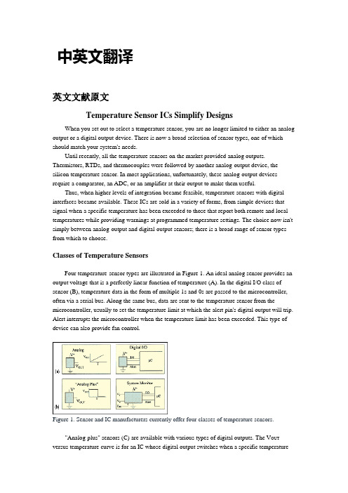
中英文翻译英文文献原文Temperature Sensor ICs Simplify DesignsWhen you set out to select a temperature sensor, you are no longer limited to either an analog output or a digital output device. There is now a broad selection of sensor types, one of which should match your system's needs.Until recently, all the temperature sensors on the market provided analog outputs. Thermistors, RTDs, and thermocouples were followed by another analog-output device, the silicon temperature sensor. In most applications, unfortunately, these analog-output devices require a comparator, an ADC, or an amplifier at their output to make them useful.Thus, when higher levels of integration became feasible, temperature sensors with digital interfaces became available. These ICs are sold in a variety of forms, from simple devices that signal when a specific temperature has been exceeded to those that report both remote and local temperatures while providing warnings at programmed temperature settings. The choice now isn't simply between analog-output and digital-output sensors; there is a broad range of sensor types from which to choose.Classes of Temperature SensorsFour temperature-sensor types are illustrated in Figure 1. An ideal analog sensor provides an output voltage that is a perfectly linear function of temperature (A). In the digital I/O class of sensor (B), temperature data in the form of multiple 1s and 0s are passed to the microcontroller, often via a serial bus. Along the same bus, data are sent to the temperature sensor from the microcontroller, usually to set the temperature limit at which the alert pin's digital output will trip. Alert interrupts the microcontroller when the temperature limit has been exceeded. This type of device can also provide fan control.Figure 1. Sensor and IC manufacturers currently offer four classes of temperature sensors."Analog-plus" sensors (C) are available with various types of digital outputs. The V OUT versus temperature curve is for an IC whose digital output switches when a specific temperaturehas been exceeded. In this case, the "plus" added to the analog temperature sensor is nothing more than a comparator and a voltage reference. Other types of "plus" parts ship temperature data in the form of the delay time after the part has been strobed, or in the form of the frequency or the period of a square wave, which will be discussed later.The system monitor (D) is the most complex IC of the four. In addition to the functions provided by the digital I/O type, this type of device commonly monitors the system supply voltages, providing an alarm when voltages rise above or sink below limits set via the I/O bus. Fan monitoring and/or control is sometimes included in this type of IC. In some cases, this class of device is used to determine whether or not a fan is working. More complex versions control the fan as a function of one or more measured temperatures. The system monitor sensor is not discussed here but is briefly mentioned to give a complete picture of the types of temperature sensors available.Analog-Output Temperature SensorsThermistors and silicon temperature sensors are widely used forms of analog-output temperature sensors. Figure 2 clearly shows that when a linear relationship between voltage and temperature is needed, a silicon temperature sensor is a far better choice than a thermistor. Over a narrow temperature range, however, thermistors can provide reasonable linearity and good sensitivity. Many circuits originally constructed with thermistors have over time been updated using silicon temperature sensors.Figure 2. The linearity of thermistors and silicon temperature sensors, two popular analog-output temperature detectors, is contrasted sharply.Silicon temperature sensors come with different output scales and offsets. Some, for example, are available with output transfer functions that are proportional to K, others to °C or °F. Some of the °C parts provide an offset so that negative temperatures can be monitored using a single-ended supply.In most applications, the output of these devices is fed into a comparator or a n A/D converter to convert the temperature data into a digital format. Despite the need for these additional devices,thermistors and silicon temperature sensors continue to enjoy popularity due to low cost and convenience of use in many situations.Digital I/O Temperature SensorsAbout five years ago, a new type of temperature sensor was introduced. These devices include a digital interface that permits communication with a microcontroller. The interface is usually an I²C or SMBus serial bus, but other serial interfaces such as SPI are common. In addition to reporting temperature readings to the microcontroller, the interface also receives instructions from the microcontroller. Those instructions are often temperature limits, which, if exceeded, activate a digital signal on the temperature sensor IC that interrupts the microcontroller. The microcontroller is then able to adjust fan speed or back off the speed of a microprocessor, for example, to keep temperature under control.This type of device is available with a wide variety of features, among them, remote temperature sensing. To enable remote sensing, most high-performance CPUs include an on-chip transistor that provides a voltage analog of the temperature. (Only one of the transistor's two p-n junctions is used.) Figure 3 shows a remote CPU being monitored using this technique. Other applications utilize a discrete transistor to perform the same function.Figure 3. A user-programmable temperature sensor monitors the temperature of a remote CPU's on-chip p-n junction.Another important feature found on some of these types of sensors (including the sensor shown in Figure 3) is the ability to interrupt a microcontroller when the measured temperature falls outside a range bounded by high and low limits. On other sensors, an interrupt is generated when the measured temperature exceeds either a high or a low temperature threshold (i.e., not both). For the sensor in Figure 3, those limits are transmitted to the temperature sensor via the SMBus interface. If the temperature moves above or below the circumscribed range, the alert signal interrupts the processor.Pictured in Figure 4 is a similar device. Instead of monitoring one p-n junction, however, it monitors four junctions and its own internal temperature. Because Maxim's MAX1668 consumes a small amount of power, its internal temperature is close to the ambient temperature. Measuring the ambient temperature gives an indication as to whether or not the system fan is operating properly.Figure 4. A user-programmable temperature sensor monitors its own local temperature and the temperatures of four remote p-n junctions.Controlling a fan while monitoring remote temperature is the chief function of the IC shown in Figure 5. Users of this part can choose between two different modes of fan control. In the PWM mode, the microcontroller controls the fan speed as a function of the measured temperature by changing the duty cycle of the signal sent to the fan. This permits the power consumption to be far less than that of the linear mode of control that this part also provides. Because some fans emit an audible sound at the frequency of the PWM signal controlling it, the linear mode can be advantageous, but at the price of higher power consumption and additional circuitry. The added power consumption is a small fraction of the power consumed by the entire system, though.Figure 5. A fan controller/temperature sensor IC uses either a PWM- or linear-mode control scheme.This IC provides the alert signal that interrupts the microcontroller when the temperature violates specified limits. A safety feature in the form of the signal called "overt" (an abbreviated version of "over temperature") is also provided. If the microcontroller or the software were to lock up while temperature is rising to a dangerous level, the alert signal would no longer be useful. However, overt, which goes active once the temperature rises above a level set via the SMBus, is typically used to control circuitry without the aid of the microcontroller. Thus, in thishigh-temperature scenario with the microcontroller not functioning, overt could be used to shutdown the system power supplies directly, without the microcontroller, and prevent a potentially catastrophic failure.This digital I/O class of devices finds widespread use in servers, battery packs, and hard-disk drives. Temperature is monitored in numerous locations to increase a server's reliability: at the motherboard (which is essentially the ambient temperature inside the chassis), inside the CPU die, and at other heat-generating components such as graphics accelerators and hard-disk drives. Battery packs incorporate temperature sensors for safety reasons and to optimize charging profiles, which maximizes battery life.There are two good reasons for monitoring the temperature of a hard-disk drive, which depends primarily on the speed of the spindle motor and the ambient temperature: The read errors in a drive increase at temperature extremes, and a hard disk's MTBF is improved significantly through temperature control. By measuring the temperature within the system, you can control motor speed to optimize reliability and performance. The drive can also be shut down. In high-end systems, alerts can be generated for the system administrator to indicate temperature extremes or situations where data loss is possible.Analog-Plus Temperature Sensors"Analog-plus" sensors are generally suited to simpler measurement applications. These ICs generate a logic output derived from the measured temperature and are distinguished from digital I/O sensors primarily because they output data on a single line, as opposed to a serial bus.In the simplest instance of an analog-plus sensor, the logic output trips when a specific temperature is exceeded. Some of these devices are tripped when temperature rises above a preset threshold, others, when temperature drops below a threshold. Some of these sensors allow the temperature threshold to be adjusted with a resistor, whereas others have fixed thresholds.The devices shown in Figure 6 are purchased with a specific internal temperature threshold. The three circuits illustrate common uses for this type of device: providing a warning, shutting down a piece of equipment, or turning on a fan.Figure 6. ICs that signal when a temperature has been exceeded are well suited forover/undertemperature alarms and simple on/off fan control.When an actual temperature reading is needed, and a microcontroller is available, sensors that transmit the reading on a single line can be useful. With the microcontroller's internal counter measuring time, the signals from this type of temperature sensor are readily transformed to a measure of temperature. The sensor in Figure 7 outputs a square wave whose frequency is proportional to the ambient temperature in Kelvin. The device in Figure 8 is similar, but the period of the square wave is proportional to the ambient temperature in kelvins.Figure 7. A temperature sensor that transmits a square wave whose frequency is proportional to the measured temperature in Kelvin forms part of a heater controller circuit.Figure 8. This temperature sensor transmits a square wave whose period is proportional to the measured temperature in Kelvin. Because only a single line is needed to send temperature information, just a single optoisolator is required to isolate the signal path.Figure 9, a truly novel approach, allows up to eight temperature sensors to be connected on this common line. The process of extracting temperature data from these sensors begins when the microcontroller's I/O port strobes all the sensors on the line simultaneously. The microcontroller is then quickly reconfigured as an input in order to receive data from each of the sensors. The data are encoded as the amount of time that transpires after the sensors are strobed. Each of the sensors encodes this time after the strobe pulse within a specific range of time. Collisions are avoided by assigning each sensor its own permissible time range.Figure 9. A microcontroller strobes up to eight temperature sensors connected on a common line and receives the temperature data transmitted from each sensor on the same line.The accuracy achieved by this method is surprisingly high: 0.8°C is typical at room temperature, precisely matching that of the IC that encodes temperature data in the form of the frequency of the transmitted square wave. The same is true of the device that uses the period of the square wave.These devices are outstanding in wire-limited applications. For example, when a temperature sensor must be isolated from the microcontroller, costs are kept to a minimum because only one optoisolator is needed. These sensors are also of great utility in automotive and HVAC applications, because they reduce the amount of copper running over distances.Anticipated Temperature Sensor DevelopmentsIC temperature sensors provide a varied array of functions and interfaces. As these devicescontinue to evolve, system designers will see more application-specific features as well as new ways of interfacing the sensors to the system. Finally, the ability of chip designers to integrate more electronics in the same die area ensures that temperature sensors will soon include new functions and special interfaces.中文翻译温度传感器芯片简化设计当选择一个温度传感器时,将不再局限于模拟输出或数字输出设备。
传感器的基础知识论文中英文资料对照外文翻译
传感器的根底知识论文中英文资料对照外文翻译英文文献翻译中英文资料对照外文翻译Basic knowledge of transducersA transducer is a device which converts the quantity being measured into an optical, mechanical, or-more commonly-electrical signal. Theenergy-conversion process that takes place is referred to as transduction.Transducers are classified according to the transduction principle involved and the form of the measured. Thus a resistance transducer for measuring displacement is classified as a resistance displacement transducer. Other classification examples are pressure bellows, force diaphragm, pressure flapper-nozzle, and so on. 1、Transducer Elements Although there are exception ,most transducers consist of a sensing element and a conversion or control element. For example, diaphragms,bellows,strain tubes and rings, bourdon tubes, and cantilevers are sensing elements which respond to changes in pressure or force and convert these physical quantities into a displacement. This displacement may then be used to change an electrical parameter such as voltage, resistance, capacitance, or inductance. Such combination of mechanical and electrical elements form electromechanical transducing devices or transducers. Similar combination can be made for other energy input such as thermal. Photo, magnetic and chemical,giving thermoelectric, photoelectric,electromaanetic, and electrochemical transducers respectively. 2、Transducer SensitivityThe relationship between the measured and the transducer output signal is usually obtained by calibration tests and is referred to as the transducer sensitivity K1= output-signal increment / measured increment .In practice, the transducer sensitivity is usually known, and, by measuring the output signal, the input quantity is determined from input= output-signal increment / K1.3、Characteristics of an Ideal TransducerThe high transducer should exhibit the following characteristicsa) high fidelity-the transducer output waveform shape be a faithful reproduction of the measured; there should be minimum distortion.b) There should be minimum interference with the quantity being measured; the presence of the transducer should not alter the measured in any way.c) Size. The transducer must be capable of being placed exactly where it is needed.1英文文献翻译d) There should be a linear relationship between the measured and the transducer signal. e) The transducer should have minimum sensitivity to external effects, pressuretransducers,for example,are often subjected to external effects such vibration and temperature. f) The natural frequency of the transducer should be well separated from the frequency and harmonics of the measurand.4、Electrical TransducersElectrical transducers exhibit many of the ideal characteristics. In addition they offer high sensitivity as well as promoting the possible of remote indication or mesdurement. Electrical transducers can be divided into two distinct groups: a) variable-control-parameter types,which include: i)resistance ii) capacitance iii) inductanceiv) mutual-inductance typesThese transducers all rely on external excitation voltage for their operation. b) self-generating types,which include i) electromagnetic ii)thermoelectric iii)photoemissive iv)piezo-electric typesThese all themselves produce an output voltage in response to the measurand input and their effects are reversible. For example, a piezo-electric transducer normally produces an output voltage in response to the deformation of a crystalline material; however, if an alternating voltage is applied across the material, the transducer exhibits the reversible effect by deforming or vibrating at the frequency of the alternating voltage. 5、Resistance TransducersResistance transducers may be divided into two groups, as follows: i) Those which experience a large resistance change, measured by using potential-divider methods. Potentiometers are in this group.ii)Those which experience a small resistance change, measured by bridge-circuit methods. Examples of this group include strain gauges and resistance thermometers. 5.1 PotentiometersA linear wire-wound potentiometer consists of a number of turns resistance wire wound around a non-conducting former, together with a wiping contact which travels over the barwires. The construction principles are shown in figure which indicate that the wiper2英文文献翻译displacement can be rotary, translational, or a combination of both to give a helical-type motion. The excitation voltage may be either a.c. or d.c. and the output voltage is proportional to the input motion, provided the measuring device has a resistance which is much greater than the potentiometer resistance.Such potentiometers suffer from the linked problem of resolution and electrical noise. Resolution is defined as the smallest detectable change in input and is dependent on the cross-sectional area of the windings and the area of the sliding contact. The output voltage is thus a serials of steps as the contact moves from one wire to next.Electrical noise may be generated by variation in contact resistance, by mechanical wear due to contact friction, and by contact vibration transmitted from the sensing element. In addition, the motion being measured may experience significant mechanical loading by the inertia and friction of the moving parts of the potentiometer. The wear on the contacting surface limits the life of a potentiometer to a finite number of full strokes or rotations usually referred to in the manufacture’s specification as the ‘number of cycles of life expectancy’, a typical value being 20*1000000 cycles.The output voltage V0 of the unload potentiometer circuit is determined as follows. Let resistance R1= xi/xt *Rt where xi = input displacement, xt= maximum possible displacement, Rt total resistance of the potentiometer. Then output voltage V0= V*R1/(R1+( Rt-R1))=V*R1/Rt=V*xi/xt*Rt/Rt=V*xi/xt. This shows that there is a straight-line relationship between output voltage and input displacement for the unloaded potentiometer. It would seen that high sensitivity could be achieved simply by increasing the excitation voltage V. however, the maximum value of V is determined by the maximum power dissipation P of the fine wires of the potentiometer winding and is given by V=(PRt)1/2 . 5.2 Resistance Strain GaugesResistance strain gauges are transducers which exhibit a change in electrical resistance in response to mechanical strain. They may be of the bonded or unbonded variety . a) bonded strain gaugesUsing an adhesive, these gauges are bonded, or cemented, directly on to the surface of the body or structure which is being examined. Examples of bonded gauges arei) fine wire gauges cemented to paper backingii) photo-etched grids of conducting foil on an epoxy-resin backingiii)a single semiconductor filament mounted on an epoxy-resin backing with copper or nickel leads.Resistance gauges can be made up as single elements to measuring strain in one direction only,3英文文献翻译or a combination of elements such as rosettes will permit simultaneous measurements in more than one direction. b) unbonded strain gauges A typical unbonded-strain-gauge arrangement shows fine resistance wires stretched around supports in such a way that the deflection of the cantilever spring system changes the tension in the wires and thus alters the resistance of wire. Such an arrangement may be found in commercially available force, load, or pressure transducers. 5.3 Resistance Temperature TransducersThe materials for these can be divided into two main groups:a) metals such as platinum, copper, tungsten, and nickel which exhibit and increase in resistance as the temperature rises; they have a positive temperature coefficient of resistance. b) semiconductors, such as thermistors which use oxides of manganese, cobalt, chromium, or nickel. These exhibit large non-linear resistance changes with temperature variation and normally have a negative temperature coefficient of resistance. a) metal resistance temperature transducersThese depend, for many practical purpose and within a narrow temperature range, upon the relationship R1=R0*[1+a*(b1-b2)] where a coefficient of resistance in ℃-1,and R0 resistance in ohms at the reference temperature b0=0℃ at the reference temperature range ℃.℃℃. b) thermistor resistance temperature transducersThermistors are temperature-sensitive resistors which exhibit large non-liner resistance changes with temperature variation. In general, theyhave a negative temperature coefficient. For small temperature increments the variation in resistance is reasonably linear; but, if large temperature changes are experienced, special linearizing techniques are used in the measuring circuits to produce a linear relationship of resistance against temperature.Thermistors are normally made in the form of semiconductor discs enclosed in glass vitreous enamel. Since they can be made as small as 1mm,quite rapid response times are possible. 5.4 Photoconductive Cells The photoconductive cell , uses a light-sensitive semiconductor material. The resistance between the metal electrodes decrease as the intensity of the light striking the semiconductor increases. Common semiconductor materials used for photo-conductive cells are cadmium sulphide, lead sulphide, and copper-doped germanium.The useful range of frequencies is determined by material used. Cadmium sulphide is mainly suitable for visible light, whereas lead sulphide has its peak response in the infra-red region4英文文献翻译and is, therefore , most suitable for flame-failure detection and temperature measurement. 5.5 Photoemissive CellsWhen light strikes the cathode of the photoemissive cell are given sufficient energy to arrive the cathode. The positive anode attracts these electrons, producing a current which flows through resistor R and resulting in an output voltage V. Photoelectrically generated voltage V=Ip.RlWhere Ip=photoelectric current(A),and photoelectric current Ip=Kt.B Where Kt=sensitivity (A/im),and B=illumination input (lumen)Although the output voltage does give a good indication of the magnitude of illumination, the cells are more often used for counting or controlpurpose, where the light striking the cathode can be interrupted. 6、Capacitive TransducersThe capacitance can thus made to vary by changing either the relative permittivity, the effective area, or the distance separating the plates. The characteristic curves indicate that variations of area and relative permittivity give a linear relationship only over a small range of spacings. Thus the sensitivity is high for small values of d. Unlike the potentionmeter, the variable-distance capacitive transducer has an infinite resolution making it most suitable for measuring small increments of displacement or quantities which may be changed to producea displacement.7、Inductive TransducersThe inductance can thus be made to vary by changing the reluctance of the inductive circuit. Measuring techniques used with capacitive and inductive transducers: a)A.C. excited bridges using differential capacitors inductors. b)A.C. potentiometer circuits for dynamic measurements.c) D.C. circuits to give a voltage proportional to velocity for a capacitor.d) Frequency-modulation methods, where the change of C or L varies the frequency of an oscillation circuit.Important features of capacitive and inductive transducers are as follows: i)resolution infiniteii) accuracy+- 0.1% of full scale is quoted iii)displacement ranges 25*10-6 m to 10-3m iv) rise time less than 50us possibleTypical measurands are displacement, pressure, vibration, sound, and liquid level. 8、 Linear Variable-differential Ttransformer 9、Piezo-electric Transducers5。
最新传感器技术外文文献及中文翻译资料

Sensor technologyA sensor is a device which produces a signal in response to its detecting or measuring a property ,such as position , force , torque , pressure , temperature , humidity , speed , acceleration , or vibration .Traditionally ,sensors (such as actuators and switches )have been used to set limits on the performance of machines .Common examples are (a) stops on machine tools to restrict work table movements ,(b) pressure and temperature gages with automatics shut-off features , and (c) governors on engines to prevent excessive speed of operation . Sensor technology has become an important aspect of manufacturing processes and systems .It is essential for proper data acquisition and for the monitoring , communication , and computer control of machines and systems .Because they convert one quantity to another , sensors often are referred to as transducers .Analog sensors produce a signal , such as voltage ,which is proportional to the measured quantity .Digital sensors have numeric or digital outputs that can be transferred to computers directly .Analog-to-coverter(ADC) is available for interfacing analog sensors with computers .Classifications of SensorsSensors that are of interest in manufacturing may be classified generally as follows:Machanical sensors measure such as quantities aspositions ,shape ,velocity ,force ,torque , pressure , vibration , strain , and mass .Electrical sensors measure voltage , current , charge , and conductivity .Magnetic sensors measure magnetic field ,flux , and permeablity .Thermal sensors measure temperature , flux ,conductivity , and special heat .Other types are acoustic , ultrasonic , chemical , optical , radiation , laser ,and fiber-optic .Depending on its application , a sensor may consist of metallic , nonmetallic , organic , or inorganic materials , as well as fluids ,gases ,plasmas , or semiconductors .Using the special characteristics of these materials , sensors covert the quantity or property measured to analog or digital output. The operation of an ordinary mercury thermometer , for example , is based on the difference between the thermal expansion of mercury and that of glass.Similarly , a machine part , a physical obstruction , or barrier in a space can be detected by breaking the beam of light when sensed by a photoelectric cell . A proximity sensor ( which senses and measures the distance between it and an object or a moving member of a machine ) can be based on acoustics , magnetism , capacitance , or optics . Other actuators contact the object and take appropriate action ( usually by electromechanical means ) . Sensors are essential to the conduct of intelligent robots , and are being developed with capabilities that resemble those of humans ( smart sensors , see the following ).This is America, the development of such a surgery Lin Bai an example, through the screen, through a remote control operator to control another manipulator, through the realization of the right abdominal surgery A few years ago our country theexhibition, the United States has been successful in achieving the right to the heart valve surgery and bypass surgery. This robot has in the area, caused a great sensation, but also, AESOP's surgical robot, In fact, it through some equipment to some of the lesions inspections, through a manipulator can be achieved on some parts of the operation Also including remotely operated manipulator, and many doctors are able to participate in the robot under surgery Robot doctor to include doctors with pliers, tweezers or a knife to replace the nurses, while lighting automatically to the doctor's movements linked, the doctor hands off, lighting went off, This is very good, a doctor's assistant.Tactile sensing is the continuous of variable contact forces , commonly by an array of sensors . Such a system is capable of performing within an arbitrarythree-dimensional space .has gradually shifted from manufacturing tonon-manufacturing and service industries, we are talking about the car manufacturer belonging to the manufacturing industry, However, the services sector including cleaning, refueling, rescue, rescue, relief, etc. These belong to the non-manufacturing industries and service industries, so here is compared with the industrial robot, it is a very important difference. It is primarily a mobile platform, it can move to sports, there are some arms operate, also installed some as a force sensor and visual sensors, ultrasonic ranging sensors, etc. It’s surrounding environment for the conduct of identification, to determine its campaign to complete some work, this is service robot’s one of the basic characteristicsIn visual sensing (machine vision , computer vision ) , cameral optically sense the presence and shape of the object . A microprocessor then processes the image ( usually in less than one second ) , the image is measured , and the measurements are digitized ( image recognition ) .Machine vision is suitable particularly for inaccessible parts , in hostile manufacturing environments , for measuring a large number of small features , and in situations where physics contact with the part may cause damage .Small sensors have the capability to perform a logic function , to conducttwo-way communication , and to make a decisions and take appropriate actions . The necessary input and the knowledge required to make a decision can be built into a smart sensor . For example , a computer chip with sensors can be programmed to turn a machine tool off when a cutting tool fails . Likewise , a smart sensor can stop a mobile robot or a robot arm from accidentally coming in contact with an object or people by using quantities such as distance , heat , and noise .Sensor fusion . Sensor fusion basically involves the integration of multiple sensors in such a manner where the individual data from each of the sensors ( such as force , vibration , temperature , and dimensions ) are combined to provide a higher level of information and reliability . A common application of sensor fusion occurs when someone drinks a cup of hot coffee . Although we take such a quotidian event for granted ,it readily can be seen that this process involves data input from the person's eyes , lips , tongue , and hands .Through our basic senses of sight , hearing , smell , taste , and touch , there is real-time monitoring of relative movements , positions , and temperatures . Thus if the coffee is too hot , the hand movement of the cup toward the lip is controlled and adjusted accordingly .The earliest applications of sensor fusion were in robot movement control , missile flight tracking , and similar military applications . Primarily because these activities involve movements that mimic human behavior . Another example of sensor fusion is a machine operation in which a set of different but integrated sensors monitors (a) the dimensions and surface finish of workpiece , (b) tool forces , vibrations ,and wear ,(c) the temperature in various regions of the tool-workpiece system , and (d) the spindle power .An important aspect in sensor fusion is sensor validation : the failure of one particular sensor is detected so that the control system maintains high reliability . For this application ,the receiving of redundant data from different sensors is essential . It can be seen that the receiving , integrating of all data from various sensors can be a complex problem .With advances in sensor size , quality , and technology and continued developments in computer-control systems , artificial neural networks , sensor fusion has become practical and available at low cost .Movement is relatively independent of the number of components, the equivalent of our body, waist is a rotary degree of freedom We have to be able to hold his arm, Arm can be bent, then this three degrees of freedom, Meanwhile there is a wrist posture adjustment to the use of the three autonomy, the general robot has six degrees of freedom. We will be able to space the three locations, three postures, the robot fully achieved, and of course we have less than six degrees of freedomFiber-optic sensors are being developed for gas-turbine engines . These sensors will be installed in critical locations and will monitor the conditions inside the engine , such as temperature , pressure , and flow of gas . Continuous monitoring of the signals from thes sensors will help detect possible engine problems and also provide the necessary data for improving the efficiency of the engines .传感器技术传感器一种通过检测某一参数而产生信号的装置。
传感器技术外文文献及中文翻译
Sensor technologyA sensor is a device which produces a signal in response to its detecting or measuring a property ,such as position , force ,torque ,pressure ,temperature ,humidity , speed ,acceleration , or vibration 。
Traditionally ,sensors (such as actuators and switches )have been used to set limits on the performance of machines 。
Common examples are (a)stops on machine tools to restrict work table movements ,(b)pressure and temperature gages with automatics shut—off features ,and (c) governors on engines to prevent excessive speed of operation . Sensor technology has become an important aspect of manufacturing processes and systems .It is essential for proper data acquisition and for the monitoring , communication ,and computer control of machines and systems 。
Because they convert one quantity to another ,sensors often are referred to as transducers .Analog sensors produce a signal ,such as voltage ,which is proportional to the measured quantity 。
传感器技术外文文献及中文翻译

传感器技术外文文献及中文翻译引言传感器是现代检测技术的重要组成部分,它能将物理量、化学量等非电信号转换为电信号,从而实现检测和控制。
传感器广泛应用于工业、医疗、军事等领域中,如温度、湿度、气压、光强度等参数检测。
随着科技的发展,传感器不断新型化、微型化和智能化,已经涵盖了人体所有的感官,开启了大规模的物联网与智能化时代。
本文将介绍几篇与传感器技术相关的外文文献,并对其中较为重要的内容进行中文翻译。
外文文献1标题“Flexible Sensors for Wearable Health: Why Materials Matter”作者Sarah O’Brien, Michal P. Mielczarek, and Fergal J. O’Brien文献概述本文主要介绍了柔性传感器在可穿戴健康监测中的应用,以及传感材料的选择对柔性传感器性能的影响。
文章先介绍了柔性传感器的基本工作原理和常见的柔性传感材料,然后重点探讨了传感材料对柔性传感器灵敏度、稳定性、响应速度等性能的影响。
最后,文章提出未来柔性传感器材料需满足的性能要求,并对可能的研究方向和应用进行了展望。
翻译摘要柔性传感器是可穿戴健康监测中重要的成分,通过将身体状态转化为电信号进行检测。
选择合适的传感材料对柔性传感器产品的成本、性能及标准化有着面向未来的影响。
本文对柔性材料的常见种类 (如: 聚合物、金属、碳复合材料等) 进行了介绍,并重点探讨了传感材料选择的影响因素,如对柔性传感器的灵敏度、特异性和响应时间等。
此外,文章还探讨了柔性传感器的性能要求和建议未来的技术方向。
外文文献2标题“Smart sensing system for precision agriculture”作者Olivier Strauss, Lucas van der Meer, and Benoit Figliuzzi文献概述本文主要介绍智能传感系统在精准农业中的应用。
传感器技术0绪论中英对照

Dr. Jinbo Fu
Chapter1:Preface
14
么么么么方面
Sds绝对是假的
Requirements of sensors 传感器的要求
足够的容量(sufficient capacity)—传感器的工作范围或量程(range)足
够大,具有一定的过载能力(overload capacity)。
Wide range of knowledge in Physics, Mechanics, Electronics, Machinery, Optics, etc. 物理、力学、电子学、机械、光学等等 广泛的知识
Good attitude & some devotion 好的学习态度 + 一些投入
Sensor/Transducer Technology
传感器技术
Instructor: Dr. Jinbo Fu (符金波)
Ph.D. of Mechanical Engineering, Penn State Univ., USA M.S. of Electrical Engineering, Penn State Univ., USA M.S. of Mechanical Engineering, Penn State Univ., USA M.E. of Precision Instrument, Tsinghua Univ., PRC B.E. of Precision Instrument, Tsinghua Univ., PRC
状态量 Quantity of
state
颜色color、透明度clarity、磨损量amount of wear、材料内部裂缝或缺陷internal fracture or defect of material、气体泄漏air leak、表面质量
传感器——通信电子工程类中英文翻译、外文翻译
What is a smart sensorOne of the biggest advances in automation has been the development and spread of smart sensors. But what exactly is a "smart" sensor? Experts from six sensor manufacturers define this term.A good working "smart sensor" definition comes from Tom Griffiths, product manager, Honeywell Industrial Measurement and Control. Smart sensors, he says, are "sensors and instrument packages that are microprocessor driven and include features such as communication capability and on-board diagnostics that provide information to a monitoring system and/or operator to increase operational efficiency and reduce maintenance costs."No failure to communicate"The benefit of the smart sensor," says Bill Black, controllers product manager at GE Fanuc Automation, "is the wealth of information that can be gathered from the process to reduce downtime and improve quality." David Edeal, Temposonics product manager, MTS Sensors, expands on that: "The basic premise of distributed intelligence," he says, is that "complete knowledge of a system, subsystem, or component's state at the right place and time enables the ability to make 'optimal' process control decisions."Adds John Keating, product marketing manager for the Checker machine vision unit at Cognex, "For a (machine vision) sensor to really be 'smart,' it should not require the user to understand machine vision."A smart sensor must communicate. "At the most basic level, an 'intelligent' sensor has the ability to communicate information beyond the basic feedback signals that are derived from its application." saysEdeal. This can be a HART signal superimposed on a standard 4-20 mA process output, a bus system, or wireless arrangement. A growing factor in this area is IEEE 1451, a family of smart transducer interface standards intended to give plug-and-play functionality to sensors from different makers.Diagnose, programSmart sensors can self-monitor for any aspect of their operation, including "photo eye dirty, out of tolerance, or failed switch," says GE Fanuc's Black. Add to this, says Helge Hornis, intelligent systems manager, Pepperl+Fuchs, "coil monitoring functions, target out of range, or target too close." It may also compensate for changes in operating conditions. "A 'smart' sensor," says Dan Armentrout, strategic creative director, Omron Electronics LLC, "must monitor itself and its surroundings and then make a decision to compensate for the changes automatically or alert someone for needed attention."Many smart sensors can be re-ranged in the field, offering "settable parameters that allow users to substitute several 'standard' sensors," says Hornis. "For example, typically sensors are ordered to be normally open (NO) or normally closed (NC). An intelligent sensor can be configured to be either one of these kinds."Intelligent sensors have numerous advantages. As the cost of embedded computing power continues to decrease, "smart" devices will be used in more applications. Internal diagnostics alone can recover the investment quickly by helping avoid costly downtime.Sensors: Getting into PositionAs the saying goes, 'No matter where you go, there you are.' Still, most applications require a bit more precision and repeatability than that, so here's advice on how to select and locate position sensors.The article contains online extra material.What's the right position sensor for a particular application? It depends on required precision, repeatability, speed, budget, connectivity, conditions, and location, among other factors. You can bet that taking the right measurement is the first step to closing the loop on any successful application.Sensor technologies that can detect position are nearly as diverse as applications in providing feedback for machine control and other uses. Spatial possibilities are linear, area, rotational, andthree-dimensional. In some applications, they're used in combination. Sensing elements are equally diverse.Ken Brey, technical director, DMC Inc., a Chicago-based system integrator, outlined some the following position-sensing options.Think digitallyFor digital position feedback:∙Incremental encoders are supported by all motion controllers; come in rotary and linear varieties and in many resolutions; are simulated by many other devices; and require a homing process to reference the machine to a physical marker, and when power is turned off.∙Absolute encoders are natively supported by fewer motion controllers; can be used by all controllers that have sufficient available digital inputs; report a complete position within theirrange (typically one revolution); and do not require homing.∙Resolvers are more immune to high-level noise in welding applications; come standard on some larger motors; simulate incremental encoders when used with appropriate servo amps; and can simulate absolute encoders with some servo amps.∙Dual-encoder feedback, generally under-used, is natively supported by most motion controllers; uses one encoder attached to the motor and another attached directly to the load; and is beneficial when the mechanical connection between motor and load is flexible or can slip.∙Vision systems , used widely for inspection, can also be used for position feedback. Such systems locate objects in multiple dimensions, typically X, Y, and rotation; frequently find parts ona conveyor; and are increasing in speed and simplicity.A metal rolling, stamping, and cut-off application provides an example of dual-encoder feedback use, Brey says. 'It required rapid and accurate indexing of material through a roll mill for a stamping process. The roll mill creates an inconsistent amount of material stretch and roller slip,' Brey explains.'By using the encoder on the outgoing material as position feedback and the motor resolver as velocity feedback in a dual-loop configuration, the system was tuned stable and a single index move provided an accurate index length. It was much faster and more accurate than making a primary move, measuring the error, then having to make a second correction move,' he says.Creative, economicalSam Hammond, chief engineer, Innoventor, a St. Louis, MO-area system integrator, suggests that the application's purpose should guide selection of position sensors; measurements and feedback don't have to be complex. 'Creative implementations can provide simple, economical solutions,' he says. For instance, for sequencing, proximity sensors serve well in many instances.Recent sensor applications include the AGV mentioned in lead image and the following.∙In a machine to apply the top seals to tea containers, proximity and through-beam sensors locate incoming packages. National Instruments vision system images are processed to find location ofa bar code on a pre-applied label, and then give appropriate motorcommands to achieve the desired position (rotation) setting to apply one of 125 label types. Two types of position sensors were used. One was a simple inductive proximity sensor, used to monitor machine status to ensure various motion components were in the right position for motion to occur. The camera also served as a position sensor, chosen because of its multi purpose use, feature location, and ability to read bar codes.∙ A progressive-die stamping machine operates in closed loop. A linear output proximity sensor provides control feedback for optimizing die operation; a servo motor adjusts die position in the bend stage. A linear proximity sensor was selected to give a dimensional readout from the metal stamping operation; data are used in a closed-loop control system.∙Part inspection uses a laser distance measurement device to determine surface flatness. Sensor measures deviation in return beams, indicating different surface attributes to 10 microns insize. An encoder wouldn't have worked because distance was more thana meter. Laser measurement was the technology chosen because it hadvery high spatial resolution, did not require surface contact, and had a very high distance resolution.An automotive key and lock assembly system uses a proximity sensor for detecting a cap in the ready position. A laser profile sensor applied with a robot measures the key profile.What to use, where?Sensor manufacturers agree that matching advantages inherent to certain position sensing technologies can help various applications.David Edeal, product marketing manager, MTS Sensors Div., says, for harsh factory automation environments, 'the most significant factors even above speed and accuracy in customer's minds are product durability and reliability. Therefore, products with inherently non-contact sensing technologies (inductive, magnetostrictive, laser, etc.) have a significant advantage over those that rely on physical contact (resistive, cable extension, etc.)'Other important factors, Edeal says, are product range of use and application flexibility. 'In other words, technologies that can accommodate significant variations in stroke range, environmental conditions, and can provide a wide range of interface options are of great value to customers who would prefer to avoid sourcing a large variety of sensor types. All technologies are inherently limited with respect to these requirements, which is why there are so many options.'Edeal suggest that higher cost of fitting some technologies to a certain application creates a limitation, such as with linear variabledifferential transformers. 'For example, LVDTs with stroke lengths longer than 12 inches are rare because of the larger product envelope (about twice the stroke length) and higher material and manufacturing costs. On the other hand, magnetostrictive sensing technology has always required conditioning electronics. With the advent of microelectronics and the use of ASICs, we have progressed to a point where, today, a wide range of programmable output types (such as analog, encoder, and fieldbus) are available in the same compact package. Key for sensor manufacturers is to push the envelope to extend the range of use (advantages) while minimizing the limitations (disadvantages) of their technologies.'Listen to your appDifferent sensor types offer distinct advantages for various uses, agrees Tom Corbett, product manager, Pepperl+Fuchs. 'Sometimes the application itself is the deciding factor on which mode of sensing is required. For example, a machine surface or conveyor belt within the sensing area could mean the difference between using a standard diffused mode sensor, and using a diffused mode sensor with background suppression. While standard diffused mode models are not able to ignore such background objects, background suppression models evaluate light differently to differentiate between the target surface and background surfaces.'Similarly, Corbett continues, 'a shiny target in a retro-reflective application may require use of a polarized retro-reflective model sensor. Whereas a standard retro-reflective sensor could falsely trigger when presented with a shiny target, a polarized retro-reflective model uses a polarizing filter to distinguish the shiny target from the reflector.'MTS' Edeal says, 'Each technology has ideal applications, which tend to magnify its advantages and minimize its disadvantages. For example, inthe wood products industry, where high precision; varied stroke ranges; and immunity to high shock and vibration, electromagnetic interference, and temperature fluxuations are critical, magnetostrictive position sensors are the primary linear feedback option. Likewise, rotary optical encoders are an ideal fit for motor feedback because of their packaging, response speed, accuracy, durability, and noise immunity. When applied correctly, linear position sensors can help designers to ensure optimum machine productivity over the long haul.'Thinking broadly first, then more narrowly, is often the best way to design sensors into a system. Edeal says, 'Sensor specifications should be developed by starting from the machine/system-level requirements and working back toward the subsystem, and finally component level. This is typically done, but what often happens is that some system-level specifications are not properly or completely translated back to component requirements (not that this is a trivial undertaking). For example, how machine operation might create unique or additional environmental challenges (temperature, vibration, etc.) may not be clear without in-depth analysis or past experience. This can result in an under-specified sensor in the worst situation or alternatively an over-specified product where conservative estimates are applied.'Open or closedEarly in design, those involved need to decide if the architecture will be open-loop or closed-loop. Paul Ruland, product manager, AutomationDirect, says, 'Cost and performance are generally the two main criteria used to decide between open-loop or closed-loop control in electromechanical positioning systems. Open-loop controls, such as stepping systems, can often be extremely reliable and accurate when properly sized for the system. The burden of tuning a closed-loop systemprior to operation is not required here, which inherently makes it easy to apply. Both types can usually be controlled by the same motion controller. A NEMA 23 stepping motor with micro-stepping drive is now available for as little as $188, compared to an equivalent servo system at about $700.'Edeal suggests, 'Control systems are created to automate processes and there are many good examples of high-performance control systems that require little if any feedback. However, where structural system (plant) or input (demand or disturbance) changes occur, feedback is necessary to manage unanticipated changes. On the process side, accuracy—both static and dynamic—is important for end product quality, and system stability and repeatability (robustness) are important for machine productivity.'For example,' Edeal says, 'in a machining or injection molding application, the tool, mold or ram position feedback is critical to the final dimension of the fabricated part. With rare exceptions, dimensional accuracy of the part will never surpass that of the position sensor. Similarly, bandwidth (response speed) of the sensor may, along with response limitations of the actuators, limit production rates.'Finally, a sensor that is only accurate over a narrow range of operating conditions will not be sufficient in these types of environments where high shock and vibration and dramatic temperature variations are common.'The latestWhat are the latest position sensing technologies to apply to manufacturing and machining processes and why?Ruland says, 'Some of the latest developments in positioning technologies for manufacturing applications can be found in even the simplest ofdevices, such as new lower-cost proximity switches. Many of these prox devices are now available for as little as $20 and in much smaller form factors, down to 3 mm diameter. Some specialty models are also available with increased response frequencies up to 20 kHz. Where mounting difficulties and cost of an encoder are sometimes impractical, proximity switches provide an attractive alternative; many position control applications can benefit from increased performance, smaller package size, and lower purchase price and installation cost.'Corbett concurs. 'Photoelectric sensors are getting smaller, more durable, and flexible, and are packed with more standard features than ever before. Some new photoelectrics are about half the size of conventional cylindrical housings and feature welded housings compared with standard glued housings. Such features are very desirable in manufacturing and machining applications where space is critical and durability is a must. And more flexible connectivity and mounting options—side mount or snout mount are available from the same product—allow users to adapt a standard sensor to their machine, rather than vice versa.'Another simple innovation, Corbett says, is use of highly visible,360-degree LED that clearly display status information from any point of view. 'Such enhanced LED indicates overload and marginal excess gain, in addition to power and output. Such sensors offer adjustable sensitivity as standard, but are available with optional tamperproof housings to prevent unauthorized adjustments.'Photoelectric SensorsPhotoelectric sensors are typically available in at least nine or more sensing modes, use two light sources, are encapsulated in three categories of package sizes, offer five or more sensing ranges, and can be purchasedin various combinations of mounting styles, outputs, and operating voltages. It creates a bewildering array of sensor possibilities and a catalog full of options.This plethora of choices can be narrowed in two ways: The first has to do with the object being sensed. Second involves the sensor's environment.Boxed inThe first question to ask is: What is the sensor supposed to detect? "Are we doing bottles? Or are we detecting cardboard boxes?" says Greg Knutson, a senior applications engineer with sensor manufacturer Banner Engineering.Optical properties and physical distances will determine which sensing mode and what light source work best. In the case of uniformly colored boxes, for example, it might be possible to use an inexpensive diffuse sensor, which reflects light from the box.The same solution, however, can't be used when the boxes are multicolored and thus differ in reflectivity. In that case, the best solution might be an opposed or retroreflective mode sensor. Here, the system works by blocking a beam. When a box is in position, the beam is interrupted and the box detected. Without transparent boxes, the technique should yield reliable results. Several sensors could gauge boxes of different heights.Distance plays a role in selecting the light source, which can either be an LED or a laser. LED is less expensive. However, because LED are a more diffuse light source, they are better suited for shorter distances. A laser can be focused on a spot, yielding a beam that can reach long distances. Tight focus can also be important when small features have tobe sensed. If a small feature has to be spotted from several feet, it may be necessary to use a laser.Laser sensors used to cost many times more than LED. That differential has dropped with the plummeting price of laser diodes. There's still a premium for using a laser, but it's not as large as in the past.Environmental challengesOperating environment is the other primary determining factor in choosing a sensor. Some industries, such food and automotive, tend to be messy, dangerous, or both. In the case of food processing, humidity can be high and a lot of fluids can be present. Automotive manufacturing sites that process engines and other components may include grit, lubricants, and coolants. In such situations, the sensor's environmental rating is of concern. If the sensor can't handle dirt, then it can't be used. Such considerations also impact the sensing range needed because it may be necessary to station the sensor out of harm's way and at a greater distance than would otherwise be desirable. Active alarming and notification may be useful if lens gets dirty and signal degrades.Similar environmental issues apply to the sensor's size, which can range from smaller than a finger to something larger than an open hand. A smaller sensor can be more expensive than a larger one because it costs more to pack everything into a small space. Smaller sensors also have a smaller area to collect light and therefore tend to have less range and reduced optical performance. Those drawbacks have to be balanced against a smaller size being a better fit for the amount of physical space available.Sensors used in semiconductor clean room equipment, for example, don't face harsh environmental conditions, but do have to operate in tight spaces. Sensing distances typically run a few inches, thus the sensorstend to be small. They also often make use of fiber optics to bring light into and out of the area where changes are being detected.Mounting, pricingAnother factor to consider is the mounting system. Frequently, sensors must be mechanically protected with shrouds and other means. Such mechanical and optical protection can cost more than the sensor itself—a consideration for the buying process. If vendors have flexible mounting systems and a protective mounting arrangement for sensors, the products could be easier to implement and last longer.List prices for standard photoelectric sensors range from $50 or so to about $100.Laser and specialty photoelectric sensors cost between $150 and $500. Features such as a low-grade housing, standard optical performance, and limited or no external adjustments characterize the lower ends of each category. The higher end will have a high-grade housing, such as stainless steel or aluminum, high optical performance, and be adjustable in terms of gain or allow timing and other options. Low-end products are suitable for general applications, while those at the higher end may offer application-specific operation at high speed, high temperature, or in explosive environments.Finally, keep in mind that one sensing technology may not meet all of the needs of an application. And if needs change, a completely different sensor technology may be required. Having to switch to a new approach can be made simpler if a vendor offers multiple technologies in the same housing and mounting footprint, notes Ed Myers, product manager at sensor manufacturer Pepperl+Fuchs. If that's the case, then one technology can be more easily swapped out for another as needs change.译文什么是智能传感器自动化领域所取得的一项最大进展就是智能传感器的发展与广泛使用。
- 1、下载文档前请自行甄别文档内容的完整性,平台不提供额外的编辑、内容补充、找答案等附加服务。
- 2、"仅部分预览"的文档,不可在线预览部分如存在完整性等问题,可反馈申请退款(可完整预览的文档不适用该条件!)。
- 3、如文档侵犯您的权益,请联系客服反馈,我们会尽快为您处理(人工客服工作时间:9:00-18:30)。
中英文对照资料外文翻译文献附件1:外文资料翻译译文传感器新技术的发展传感器是一种能将物理量、化学量、生物量等转换成电信号的器件。
输出信号有不同形式,如电压、电流、频率、脉冲等,能满足信息传输、处理、记录、显示、控制要求,是自动检测系统和自动控制系统中不可缺少的元件。
如果把计算机比作大脑,那么传感器则相当于五官,传感器能正确感受被测量并转换成相应输出量,对系统的质量起决定性作用。
自动化程度越高,系统对传感器要求越高。
在今天的信息时代里,信息产业包括信息采集、传输、处理三部分,即传感技术、通信技术、计算机技术。
现代的计算机技术和通信技术由于超大规模集成电路的飞速发展,而已经充分发达后,不仅对传感器的精度、可靠性、响应速度、获取的信息量要求越来越高,还要求其成本低廉且使用方便。
显然传统传感器因功能、特性、体积、成本等已难以满足而逐渐被淘汰。
世界许多发达国家都在加快对传感器新技术的研究与开发,并且都已取得极大的突破。
如今传感器新技术的发展,主要有以下几个方面:利用物理现象、化学反应、生物效应作为传感器原理,所以研究发现新现象与新效应是传感器技术发展的重要工作,是研究开发新型传感器的基础。
日本夏普公司利用超导技术研制成功高温超导磁性传感器,是传感器技术的重大突破,其灵敏度高,仅次于超导量子干涉器件。
它的制造工艺远比超导量子干涉器件简单。
可用于磁成像技术,有广泛推广价值。
利用抗体和抗原在电极表面上相遇复合时,会引起电极电位的变化,利用这一现象可制出免疫传感器。
用这种抗体制成的免疫传感器可对某生物体内是否有这种抗原作检查。
如用肝炎病毒抗体可检查某人是否患有肝炎,起到快速、准确作用。
美国加州大学巳研制出这类传感器。
传感器材料是传感器技术的重要基础,由于材料科学进步,人们可制造出各种新型传感器。
例如用高分子聚合物薄膜制成温度传感器;光导纤维能制成压力、流量、温度、位移等多种传感器;用陶瓷制成压力传感器。
高分子聚合物能随周围环境的相对湿度大小成比例地吸附和释放水分子。
高分子电介常数小,水分子能提高聚合物的介电常数。
将高分子电介质做成电容器,测定电容容量的变化,即可得出相对湿度。
利用这个原理制成等离子聚合法聚苯乙烯薄膜温度传感器,其有以下特点:测湿范围宽;温度范围宽,可达-400℃~+1500℃;响应速度快,小于1S;尺寸小,可用于小空间测湿;温度系数小。
陶瓷电容式压力传感器是一种无中介液的干式压力传感器。
采用先进的陶瓷技术和厚膜电子技术,其技术性能稳定,年漂移量小于0.1%F.S,温漂小于±0.15%/10K,抗过载强,可达量程的数百倍。
测量范围可从0到60mpa。
德国E+H公司和美国Kahlo公司产品处于领先地位。
光导纤维的应用是传感材料的重大突破,其最早用于光通信技术。
在光通信利用中发现当温度、压力、电场、磁场等环境条件变化时,引起光纤传输的光波强度、相位、频率、偏振态等变化,测量光波量的变化,就可知道导致这些光波量变化的温度、压力、电场、磁场等物理量的大小,利用这些原理可研制出光导纤维传感器。
光纤传感器与传统传感器相比有许多特点:灵敏度高,结构简单、体积小、耐腐蚀、电绝缘性好、光路可弯曲、便于实现遥测等。
光纤传感器日本处于先进水平。
如Idec Izumi公司和Suns公司。
光纤传感受器与集成光路技术相结合,加速光纤传感器技术的发展。
将集成光路器件代替原有光学元件和无源光器件,使光纤传感器有高的带宽、低的信号处理电压,可靠性高,成本低。
半导体技术中的加工方法有氧化、光刻、扩散、沉积、平面电子工艺,各向导性腐蚀及蒸镀,溅射薄膜等,这些都已引进到传感器制造。
因而产生了各种新型传感器,如利用半导体技术制造出硅微传感器,利用薄膜工艺制造出快速响应的气敏、湿敏传感器,利用溅射薄膜工艺制压力传感器等。
日本横河公司利用各向导性腐蚀技术进行高精度三维加工,制成全硅谐振式压力传感器。
核心部分由感压硅膜片和硅膜片上面制作的两个谐振梁结成,两个谐振梁的频差对应不同的压力,用频率差的方法测压力,可消除环境温度等因素带来的误差。
当环境温度变化时,两个谐振梁频率和幅度变化相同,将两个频率差后,其相同变化量就能够相互抵消。
其测量最高精度可达0.01%FS。
美国Silicon Microstructure Inc.(SMI)公司开发一系列低价位,线性度在0.1%到0.65%范围内的硅微压力传感器,最低满量程为0.15psi(1KPa),其以硅为材料制成,具有独特的三维结构,轻细微机械加工,和多次蚀刻制成惠斯登电桥于硅膜片上,当硅片上方受力时,其产生变形,电阻产生压阻效应而失去电桥平衡,输出与压力成比例的电信号.象这样的硅微传感器是当今传感器发展的前沿技术,其基本特点是敏感元件体积为微米量级,是传统传感器的几十、几百分之一。
在工业控制、航空航天领域、生物医学等方面有重要的作用,如飞机上利用可减轻飞机重量,减少能源。
另一特点是能敏感微小被测量,可制成血压压力传感器。
中国航空总公司北京测控技术研究所,研制的CYJ系列溅谢膜压力传感器是采用离子溅射工艺加工成金属应变计,它克服了非金属式应变计易受温度影响的不足,具有高稳定性,适用于各种场合,被测介质范围宽,还克服了传统粘贴式带来的精度低、迟滞大、蠕变等缺点,具有精度高、可靠性高、体积小的特点,广泛用于航空、石油、化工、医疗等领域。
集成传感器的优势是传统传感器无法达到的,它不仅仅是一个简单的传感器,其将辅助电路中的元件与传感元件同时集成在一块芯片上,使之具有校准、补偿、自诊断和网络通信的功能,它可降低成本、增加产量,美国LUCAS、NOVASENSOR公司开发的这种血压传感器,每星期能生产1万只。
智能化传感器是一种带微处理器的传感器,是微型计算机和传感器相结合的成果,它兼有检测、判断和信息处理功能,与传统传感器相比有很多特点:具有判断和信息处理功能,能对测量值进行修正、误差补偿,因而提高测量精度;可实现多传感器多参数测量;有自诊断和自校准功能,提高可靠性;测量数据可存取,使用方便;有数据通信接口,能与微型计算机直接通信。
把传感器、信号调节电路、单片机集成在一芯片上形成超大规模集成化的高级智能传感器。
美国HONY WELL公司ST-3000型智能传感器,芯片尺寸才有3×4×2mm3,采用半导体工艺,在同一芯片上制成CPU、EPROM、静压、压差、温度等三种敏感元件。
智能化传感器的研究与开发,美国处于领先地位。
美国宇航局在开发宇宙飞船时称这种传感器为灵巧传感器(Smart Sensor),在宇宙飞船上这种传感器是非常重要的。
我国在这方面的研究与开发还很落后,主要是因为我国半导体集成电路工艺水平有限。
传感器的发展日新月异,特别是80年代人类由高度工业化进入信息时代以来,传感器技术向更新、更高的技术发展。
美国、日本等发达国家的传感器技术发展最快,我国由于基础薄弱,传感器技术与这些发达国家相比有较大的差距。
因此,我们应该加大对传感器技术研究、开发的投入,使我国传感器技术与外国差距缩短,促进我国仪器仪表工业和自化化技术的发展。
附件2:外文原文Development of Sensor New Technology Sensor is one kind component which can transform the physical quantity, chemistry quantity and the biomass into electrical signal. The output signal has the different forms like the voltage,the electric current, the frequency, the pulse and so on, which can satisfy the signal transmission, processing, recording, and demonstration and control demands. So it is the automatic detection system and in the automatic control industry .If automatic Technology is used wider, then sensor is more important. In information age, the information industry includes information gathering, transmission, process three parts, namely sensor technology, communication, computer technology. Because of ultra large scale integrated circuit’s rapid development after having been developed Modern computer technology and communication, not only requests sensor precision reliability, speed of response and gain information content request more and more high but also requests its cost to be inexpensive. The obvious traditional sensor is eliminated gradually because of the function, the characteristic, the volume, the cost and so on. As world develop many countries are speeding up to the sensor new technology’s research and the development, and all has obtained the enormous breakthrough. Now the sensor new technology development mainly has following several aspects:Using the physical phenomenon, the chemical reaction, the biological effect as the sensor principle therefore the researches which discovered the new phenomenon and the new effect are thesensor technological improving ways .it is important studies to developed new sensor’s the foundation. Japanese Sharp Corporation uses the superconductivity technology to develop successfully the high temperature superconductivity magnetic sensor and get the sensor technology significant breakthrough. Its sensitivity is so high and only inferior in the superconductivity quantum interference component. Its manufacture craft is far simpler than the superconductivity quantum interference component. May use in magnetism image formation technology. So it has the widespread promoted value.Using the immune body and the antigen meets one another compound when the electrode surface. It can cause the electrode potential change and use this phenomenon to be possible to generate the immunity sensor. The immunity sensor makes with this kind of immune body may to some organism in whether has this kind of ant original work inspection. Like may inspect somebody with the hepatitis virus immune body whether contracts the hepatitis, plays to is fast, the accurate role. The US UC sixth branch has developed this kind of sensor.The sensor material is the important foundation for sensor technology, because the materials science is progressive and the people may make each kind of new sensor For example making thetemperature sensor with the high polymer thin film; The optical fiber can make the pressure, the current capacity, the temperature, the displacement and so on the many kinds of sensors; Making the pressure transmitter with the ceramics. The high polymer can become the proportion adsorption and the release hydrogen along with the environment relative humidity size. The high polymer electricity lies between the constant to be small, the hydrogen can enhance the polymer the coefficient of dialectical loss. Making the capacitor the high polymer dielectric medium, determines the electric capacity cape city the change, then obtains the relative humidity. Making the plasma using this principle to gather the legitimate polystyrene film temperature sensor below, it has the characteristic.Measured the wet scope is wide; The temperature range is wide, may reach -400 ℃~ +1,500 ℃; The speed of response is quick, is smaller than 1S; The size is small, may use in the small space measuring wet; The temperature coefficient is small.The ceramic electric capacity type pressure transmitter is one kind does not have the intermediary fluid the dry type pressure transmitter. Uses the advanced ceramic technology, the heavy film electronic technology, its technical performance is stable, the year drifting quantity is smaller than 0.1%F.S, warm floats is smallerthan ±0.15%/10K, anti- overloads strongly, may reach the measuring range several hundred times. The survey scope may from 0 to 60mpa.German E+H Corporation and the American Kahlo Corporation product is at the leading position.The optical fiber application is send the material significant breakthrough, its uses in most early the optical communication techniques. In the optical communication use discovered works as environmental condition change and so on the temperature, pres-sure, electric field, magnetic field, causes the fiber optic transmission light wave intensity, the phase, the frequency, change and so on the polarization condition, the survey light wave quantity change, may know causes these light wave physical quantity the and so on quantitative change temperature, pressure ,electric field, magnetic field size, uses these principles to be possible to develop the optical fiber sensor. The optical fiber sensor and the traditional sensor compare has many characteristics: Sensitivity high, the structure simple, the volume small, anti-corrosive, the electric insulation good, the path of rays may be curving, be advantageous for the realization telemeter and so on. Optical fiber sensor Japan is in the advanced level. Like Idec Izumi Corporation and Sun x Corporation. The optical fiber send receiver and the integrated path of rays technology unify, accelerates the optical fiber sensortechnology development. Will integrate the path of ray’s component to replace the original optics part and the passive light component; enable the optical fiber sensor to have the high band width, the low signal processing voltage, the reliability high, the cost will be low.In semiconductor technology processing method oxygenation, the photo etc hang, the proliferation, the deposition, the plane electron craft, various guides corrosion and steams plates, the sputtering thin film and so on, these have all introduced to the sensor manufacture. Thus has produced each kind of new sensor, like makes the silicon micro sensor using the semiconductor technology, makes the fast response using the thin film craft the gas to be sensitive, the wet sensitive sensor, the use sputtering thin film craft system pressure transmitter and so on..The Japanese horizontal river company uses various guides’ corrosion technology to carry on the high accuracy three dimensional processing; the system helps the silicon resonance type pressure transmitter. The core partially presses two resonant Liang by the feeling which above the silicon diaphragm and the silicon diaphragm manufactures to form, two resonant Liang's frequency difference correspondence different pressure, measures the pressure with the frequency difference method, may eliminate the error which factor and so on ambient temperature brings. When ambienttemperature change, two resonant Liang frequencies and the amplitude variation are same, after two frequency differences, its same change quantity can counterbalance mutually. It’s survey most high accuracy may reach 0.01%FS.American Silicon Microstructure Inc.(SMI) the company develops a series of low ends, linear in 0.1% to 0.In 65% scope silicon micro pressure transmitter, the lowest full measuring range is 0.15psi (1KPa), it makes take the silicon as the material, has the unique three dimensional structure, the light slight machine-finishing, makes the wheat stone bridge many times with the etching on the silicon diaphragm, when above silicon chip stress, it has the distortion, the resistance produces presses the anti- effect but to lose the bridge balance, the output and the pressure becomes the proportion the electrical signal.Such silicon micro sensor is the front technology which now the sensor develops, Its essential feature is the sensitive unit volume is a micron magnitude, Is the traditional sensor several dozens, several 1%. In aspect and so on industry control, aerospace domain, biomedicine has the vital role, like on the airplane the use may reduce the airplane weight, reduces the energy. Another characteristic is can be sensitive is small surveyed, may make the blood pressure pressure transmitter.The Chinese aviation main corporation Beijing observation and control technical research institute, the development CYJ series splashes thanks the membrane pressure transmitter is uses the ion sputtering craft to process the metal strain gauge, it has over come the nonmetallic strain gauge easily the temperature influence insufficiency, has the high stability, is suitable in each kind of situation, is measured the medium scope widely, but also overcame the tradition lowly to glue the precision which the type brought, sluggish big, shortcoming and so on slow change, had the precision high, the re-liability is high, the volume small characteristic, widely used in domain and so on aviation, petroleum, chemical industry, medical service.Integrates the sensor the superiority is the traditional sensor is unable to achieve, it is a simple sensor not merely, it in at the same time the auxiliary circuit part and send the part will integrate on together the chip, will cause it to have the calibration, to compensate, from the diagnosis and the network correspondence function, it might reduce the cost, the gain in yield, this kind of blood pressure sensor which American LUCAS, NOVASENSOR Corporation will develop, each week will be able to produce 10,000.The intellectualized sensor is one kind of belt microprocessor sensor, is achievement which the microcomputer and the sensorunifies, it has at the same time the examination, the judgment and the information processing function, compares with the traditional sensor has very many characteristics:Has the judgment and the information processing function, can carry on the revision, the error to the observed value compensates, thus enhancement measuring accuracy; May realize the multi-sensor multi parameters survey; Has from the diagnosis and from the calibration function, enhances the reliability; The survey data may deposit and withdraw, easy to operate; Has the data communication interface, can and the microcomputer direct communication.The sensor, the signal adjustment electric circuit, the monolithic integrated circuit integration forms ultra large-scale integrated on a chip the senior intelligence sensor. American HONY WELL Corporation ST-3000 intelligence sensor, the chip size only then has 3×4×2mm3, uses the semiconductor craft, makes CPU, EPROM, the static pressure, the differential pressure, the temperature on the identical chip and so on three kind of sensitive units.The intellectualized sensor research and the development, US is at the leading position. American Space Agency when development spaceship called this kind of sensor for the clever sensor (Smart Sensor), on the spaceship this kind of sensor isextremely important. Our country in this aspect research and development also very backward mainly is because our country semiconductor integrated circuit technological level is limited.The sensor’s development is changing day after day since especially the 80's humanities have entered into the high industrialization the information age, sensor techno-logy to renewal, higher technological development. US, Japan and so on developed country sensor technological development quickest, our country because the foundation is weak, the sensor technology compares with these developed countries has the big disparity. Therefore, we should enlarge to the sensor engineering research, the development investment, causes our country sensor technology and the foreign disparity reduces, promotes our country instrument measuring appliance industry and from the technical development.。