机车速度表使用维护说明书
机车维护技术手册

机车维护技术手册1. 引言机车是重要的铁路运输装备,而机车维护对于确保列车安全运行至关重要。
本技术手册旨在提供机车维护的详细步骤和流程,以帮助维修人员正确有效地进行维护工作。
2. 安全准备在进行任何机车维护工作之前,必须做好安全准备工作。
包括佩戴个人防护装备,确保工作区域明亮清洁,遵守操作规程和安全程序等。
3. 机车检查3.1 机车外观检查维修人员应全面检查机车外观,包括车身、车轮、底盘以及接头部分。
任何损坏、磨损或松动的部件都需要记录和修复。
3.2 机车内部检查在内部检查过程中,维修人员应仔细检查机车的各个系统,包括电气系统、机械系统和传动系统等。
发现异常情况时,需要及时汇报和修复。
4. 维护步骤4.1 清洁和润滑维修人员应定期对机车进行清洁和润滑。
清洁工作包括清除灰尘、污渍和杂物,确保机车的表面干净整洁。
润滑工作包括对关键部件进行润滑,以减少磨损和摩擦。
4.2 检修和更换维修人员应根据机车维护计划,按照规定的时间间隔进行检修和更换工作。
检修工作包括对关键部件进行检查和测试,确保其正常运行。
更换工作包括对磨损或老化的部件进行更换,以提升机车的可靠性和安全性。
4.3 故障排除如果机车出现故障,维修人员应根据故障现象和报警信息来进行排除工作。
排除过程中,应遵循标准化的故障排除流程,逐步排查和解决问题。
5. 维护记录每次进行机车维护工作时,维修人员都应准确记录维护内容和日期。
这些记录有助于形成机车的维护历史,为今后的维护工作提供参考。
6. 结论机车维护是确保列车安全运行的关键步骤。
本技术手册提供了详细的机车维护流程,帮助维修人员正确有效地进行维护工作。
维修人员在进行机车维护时,务必遵循操作规程和安全程序,确保工作的顺利进行。
通过合理的维护措施,可以延长机车的寿命,提升机车的可靠性和安全性。
车辆速度表检验台的使用与维护
的前部加止动块 ( 于前轮驱动 车辆拉 紧驻车制动 ) 对 。
() 3 起动汽 车 , 缓慢 加速 , 当车速表 指示 在 4 m/ 稳 0k h
定车速 3~ 进行测量 , 5s 检测结 束将变 速器至 于空挡 , 速 减
停车 。
() 2 举升器 : 为液压式 、 分 机械式和气 动式 ( 常用 ) 降下 ,
3 检测操作规程
() 8 调整气泵压力不得超 过 08M a . P。
() 9 对台架表面不应用腐 蚀性 液体擦 试 , 擦试 时不要有 划 迹 , 常保持 清洁。 经 5 车速表检验 台定期检查维护项 目
车速表检验 台定 期检查维护项 目见表 1 。
表 1 车速表检验 台检 查维 护项 目表
() 6 要对 滚筒支撑轴承进行 定期润滑。
( ) 期对水 过滤器 进 行放 水 , 对 油雾器加 油 ( 7定 并 一般
用 N 2机 械 油 ) 3 。
() 3 清洁滚筒上 的油 、 、 水 泥沙 等杂 物 。 () 4 检查滚 筒处 于静 止状 态 时 , 示仪 表 的零 点位 置 , 指 如有偏差 应予 以调整 。 ( ) 通气 泵 电 源 , 查 举升 板 的动 作 是 否 自如 和 同 5接 检 步, 汽缸及气管有无漏气 。
动磨擦 片 、 组装后试机时挂挡 已恢 复正常 。
8 液压缸拉伤的修理
学清洗 的时 间 , 以防合金 表面变 黑 , 后再 用 3活化液 清除 然 。 杂质 , 行钎焊表面 的碱铜 和刷镀快速镍 。 进 () 6 刷镀碱铜 和 快速 镍 : 增强 钎焊 表 面的强度 , 为 先刷 ・Βιβλιοθήκη 9 ・ 3 维普资讯
总第 19期 5 6 电气 常见故 障及排除方法
铁路机车车辆运用、检修、维护、保养与标准规范全书

铁路机车车辆运用、检修、维护、保养与标准规范全书方明群主编第二节!"#$型餐车给水装置(%$%&)…………………………………………………第四章车辆供水装置故障检修维护(%$#’)……………………………………………第一节水箱漏水的修理(%$#’)………………………………………………………第二节阀类与管系故障及修理(%$#’)………………………………………………第三节电动水泵供水系统的故障及检修(%$#%)……………………………………第十二篇列车运行监控记录装置(%$#()……………………………………………第一章列车运行监控记录装置概述(%$#$)……………………………………………第一节监控装置的特征(%$#$)………………………………………………………第二节监控装置的功能和主要技术参数(%$#))……………………………………第二章列车运行监控装置速度监控原理(%$(’)………………………………………第一节影响列车运行的因素(%$(’)…………………………………………………第二节列车制动距离的计算(%$($)…………………………………………………第三章列车运行监控装置的使用(%$*’)………………………………………………第一节+,-./(型监控装置的使用(%$*’)…………………………………………第二节-,.#0型监控装置的使用(%$)#)…………………………………………第四章列车运行监控装置的检测与维修(%$&&)………………………………………第一节调试与检测(%$&&)……………………………………………………………第二节常见故障分析与处理(%$/))…………………………………………………第十三篇机车车辆运用与检修管理(%)#%)………………………………………第一章机车运用管理(%)#()……………………………………………………………第一节电力机车管理与配置(%)#()…………………………………………………第二节内燃机车的管理与配置(%)*1)………………………………………………第二章车辆运用管理(%))’)……………………………………………………………第一节货车定检扣车(%))%)…………………………………………………………第二节色票及常用表报的使用(%))#)………………………………………………第三节客货车检修统计办法(%)1))…………………………………………………第四节车辆的备用和解除(%)11)……………………………………………………第五节车辆清查(%)1/)………………………………………………………………第六节守车管理(%)&%)………………………………………………………………第七节客车备品交接(%)&#)…………………………………………………………第八节国际联运车辆(%)&()…………………………………………………………第九节爱车工作(%)&*)………………………………………………………………·/·目录第十节车辆质量监督(!"#$)…………………………………………………………第十一节旅客列车运行中的有关要求和车电机具方面的规定(!"##)……………第十二节车辆报废(!"#%)……………………………………………………………第三章机车运用组织与调度管理(!"%&)………………………………………………第一节机车运用组织及职责(!"%&)…………………………………………………第二节机车运用管理的内容(!"%’)…………………………………………………第三节机车调度工作管理(!"%()……………………………………………………第四节机车日(班)计划的编制和掌握(!"%%)………………………………………第五节机车交路及机车运转制(!$)&)………………………………………………第六节乘务制度及乘务员换班方式(!$)")…………………………………………第四章机车运用检修指标及计算(!$!!)………………………………………………第一节机车运用指标(!$!!)…………………………………………………………第二节机车运用数量指标的计算(!$!&)……………………………………………第三节机车运用效率指标的计算(!$!()……………………………………………第四节机车检修指标及计算(!$&$)…………………………………………………第十四篇机车车辆运用可靠性分析(!$**)………………………………………第一章机车车辆可靠性概述(!$*()……………………………………………………第一节可靠性基本概念(!$*()………………………………………………………第二节可靠性概率基础(!$’!)………………………………………………………第二章机车车辆故障及分析(!$())……………………………………………………第一节故障模式(!$())………………………………………………………………第二节常用故障分析方法(!$"!)……………………………………………………第三章机车车辆运用可靠性分析(!$$))………………………………………………第一节可靠性数据收集(!$$))………………………………………………………第二节可靠性数据的处理与分析(!$$*)……………………………………………第四章机车的寿命评估(!$##)…………………………………………………………第一节机车寿命分布类型(!$##)……………………………………………………第二节分布参数的确定———点估计与区间估计(!$%*)……………………………第十五篇机车车辆运用维修相关标准规范(!#)*)………………………………·)!·目录!!!!!!!!!!!!!!!!!!!!!!!!!!!!!!!!!!!!!!!!!!!!!!!!!!!!!!!!!!!!!!!!!!!!!!!!!!!!!!!!!!!!!!!!!!!!!!!!!!!!!!!!!!!!!!!!!!!!!!!!!!!!!!!!!!!!!!!!!!!!!!!!!!!!!!!!!!!!!!!!!!!!!!!!!!!!!!!!!!!!!!!!!!!!!!!!!!!!!!!!!!!!!!!!!!!!!!!!!!!!!!!!!!!!!!!!!!!!!!!!!!!!""""第一篇机车运用第一章铁路行车信号一、铁路信号概述铁路信号是保证行车安全,提高区间和车站通过能力以及编组站编解能力的自动控制及远程控制技术的总称,其主要功能是保证行车安全,提高运输效率。
速度检测仪安全操作及保养规程

速度检测仪安全操作及保养规程随着社会的发展和交通工具的日益普及,道路交通安全成为了人们关注的焦点,严格打击超速现象也成为了治理交通安全的重要措施之一。
速度检测仪作为交警查处超速的重要工具之一,在工作中扮演着重要的角色。
本文将介绍速度检测仪的安全操作以及保养规程。
一、安全操作规程1. 确保设备正常在使用速度检测仪前,必须先检查设备是否正常运行。
具体操作如下:•检查充电电池是否充足,如果电池电量不足,必须先充电再使用•检查测速仪的触发器是否灵敏,若发现问题,请先对触发器进行调整•检查仪器的显示屏是否正常,如发现屏幕出现故障,应先排除故障再使用2. 选择合适的位置在使用速度检测仪时,必须选择合适的位置,如:•停在安全区域内,不得停在主干道上或人流密集区域内•设置稳定的基础为仪器提供足够的支持•与车辆保持一定的距离,在保证个人安全的前提下,确保设备使用的准确性3. 进行标准化操作一定要按照标准化操作程序进行检测。
注意事项如下:•操作前,必须阅读并熟悉使用速度检测仪的使用手册•操作前,必须保证测速仪触发器灵敏度是根据指南进行调整的•操作中,如有疑问或遇到问题,请及时与相关人员沟通4. 安全操作在进行测速时,必须进行安全操作:•驾驶员必须按照规定行驶•测速员必须将测速仪放置于稳定位置•在测速时必须保证测速仪的视线没有遮挡,尽可能的避免光线或其他影响测速精度的干扰•在进行车辆追逐时,要注意安全,不要过度追击二、保养规程为保持速度检测仪的使用性能,我们需要定期进行保养。
下面是保养规程:1. 定期清洁速度检测仪在使用过程中,因为环境和天气的影响,可能会存在污渍和灰尘等脏物,定期清洁是保持仪器使用性能的必要条件。
清洁时需要注意以下事项:•清洁时请注意防水,一定要确认仪器关闭•清洁时请使用干燥而柔软的布或专门的清洁剂,避免使用不当的清洁液体•清洁时请尽量避免清洗仪器中的触摸屏,如果必须清洗,请注意防水2. 定期校准为了保证速度检测仪的测值准确性,我们需要对仪器进行定期校准,校准周期一般为一年。
IMR5-CZ04 仪表说明书

⚫ 保护功能无缺陷 如果您认为接地保护等保护功能还不完善,请不要运行本仪表。 在运行之前请确认保护功能是否完善。
⚫ 在气体中使用 请不要在可燃性气体、爆炸性气体或者有蒸汽的场所运行本仪表。 在这样的环境下使用本仪表非常危险。
User’s Manual
使用说明书
IMR5-CZ04
前言 注意 版本
前言
感谢您购买本公司产品! 本手册是关于仪表的功能、设置、接线方法、操作方法、故障时的 处理方法等的说明书。在操作之前请仔细阅读本手册,正确使用。 在您读完后,请妥善保管在便于随时翻阅的地方,以便操作时参照。
⚫ 本手册内容如因功能升级等修改时,恕不通知。 ⚫ 关于本手册内容我们力保正确无误,但是当您发现有不妥或错误
附属品
配有下述附件。确认有无短缺或损伤。
序号 1 2 3 4 5
名称 安装支架 使用说明书 合格证 光盘 通讯数据线
6 U盘
7 SD 卡
数量 2 1 1 1 1
1
1
备注 用于面板安装固定 需订购 生产日期 需订购 1.5m(订购通讯接口为 RS232 时) 订购 U 盘转存功能时,容量以用户订购 为准,最大 32GB。 订购 SD 卡存储功能时,容量以用户订购 为准,最大 32GB。
IV
目录
目录
第1章
1.1 1.2 1.3 1.4 1.5 1.6 1.7 1.8 1.9
第2章
2.1 2.2 2.3 2.4 2.5 2.6 2.7 2.8 2.9
第3章
3.1 3.2 3.3 3.4 3.5
第4章
SRMAX300仪表使用说明

使用高德SDK深度开发 使用高德SDK深度开发,千万级别的POI,周边服务上、下班必用的轻导航与传统导航地图不同,亿连着重关注日常上、下班的拥堵问题,熟路导航,一键避堵km/L8.5120km/h5.3x1000/min2018.05.0310:45PM-15°C12.2ASRABSODO TRIP1TRIP2MAX AVG000000.0km聚合多个正版内容资源一个APP,在车上收听包括QQ音乐、喜马拉雅、蜻蜓FM、考拉、多听等多个APP的内容,正版授权。
QQ音乐随时听在办公室、家中所听的音乐,上车接着听。
通过同步,支持QQ个性电台,缓存音乐,及丰富的流行车友社区长按右手柄上MODE 键,切换模式显示,切换顺序如下:【小于3秒以内为“短按”功能,超过3秒为“长按”功能】。
ODO000000km km 000000km/h 000km/h 000km/l00TRIP A BMAX AVGODO 闪烁时手机互联界面(ODO 高亮显示时)2.安卓系统手机需成功连接外部“蓝牙”设备(如蓝牙耳机) 因为:完成互联后,声音是通过外部“蓝牙”设备声音输出的3.完成上述功能后,如下图操作,完成镜像功能 km/L8.5120km/h5.3x1000/min2018.05.031:45PM-15°C12.2ASRABSODO TRIP1TRIP2MAX AVG000000.0km版本显示Version display显示Display日期/时间Date / time手机互联Mobile Internet手机平台Mobile platform苹果系统ios 安卓系统android长按[MODE 键]km/L8.5120km/h5.3x1000/min2018.05.031:45PM-15°CASRABSODO TRIP1TRIP2MAX AVG000000.0kmkm/L8.52018.05.031:45-15°CASRABSODO TRIP1TRIP2MAX AVG000000.0km名,图示红色标注部分“87495”是随机生成的。
Honda NMEA 2000 速度表和发动机速度计说明书

Honda NMEA 2000®The Honda NMEA 2000® tachometer and speedometer gauges display engine and vessel data received from up to five engines on the same NMEA 2000 backbone or bus. These gauges feature analog pointers for engine RPM and vessel speed as well as a two-color graphic LCD display, programmable in English or Metric units, with push-button operations for custom display set-up. The gauges are completely sealed and feature anti-fog coated lenses.These gauges can be used as a pair or separately and connect directly to a NMEA 2000 backbone or bus. Display data includes: Engine RPM, Coolant temperature, fuel rate, fuel used, fuel level, trim, battery voltage, engine hours, and vessel speed*.* Requires NMEA 2000 GPS input to backbone.Use of these gauges and gauge harnessFt. Long requires that the vessel have:1. A properly installed and powered NMEA 2000 backbone (bus)2.Installation of an NMEA 2000 Signal Cable from the NMEA compatible Honda Marine engine to the NMEA 2000 backbone.•9.8 Ft. Long NMEA 2000 Signal Cable, P/N 06653-ZZ3-730HE or•19.5 Ft. Long NMEA 2000 Signal Cable, P/N 06653-ZZ3-760HESee NMEA Components chapter for additional information and applicable model listing.NMEA 2000® Waterproof TachometerIncludes Tachometer (7000 rpm), drop cable harness, and T connector.NMEA 2000® WaterproofSpeedometerIncludes speedometer (70 mph), dropcable, and T connector.NMEA 2000® Gauge DropCable HarnessThis NMEA harness is used to connectthe Honda NMEA compatible gauge tothe vessel backbone or bus. Theharness is 19.5 in. long.NOTE: This is a replacement harnessfor the NMEA 2000 gauges shown tothe left. This harness is not required forthe HD-4 Multi-function color display. White06326-ZX2-T13AHBlack06326-ZX2-U03AHWhite06373-ZX2-A73AHBlack06373-ZX2-B73AHNMEA 2000 DropCable Harness,19.5 in. long06326-ZX2-000EU8586Honda NMEA 2000®NMEA 2000® HD-4 Multi-function Color DisplayBright, clear, and easily visible during the day or night, the HD-4 display offers a smart interface to engine data, fuelmanagement, and more. Connected to your boat’s NMEA 2000 network, the HD-4 automatically detects and displays the most relevant information available on a series of pre-set and user-customizable data pages. HD-4 gauges support up to four (4) engine installations, and can display two (2) engines per instrument.NMEA 2000HD-4 Multi-function Color Display06333-ZX2-001AH87Veethree Gauge Sets5 Gauge Set - White Face/Domed LensIncludes : 10~65 mph speedometer, 7k tach/hour meter, trim meter, volt meter, fuel gauge.Features:•Fog-free lens coating •Backlit dial face •Digital hour meter•Engine on Demand Technology only logs hours on hour meter when engine is runningRequires Teleflex instrument harness for installation, Part No. 32200-ZW7-000AH.Instrument Harness (Fused) 7.5 AmpConnects Veethree 5 gauge set plus optional water pressure gauge to main harness. 54 inches long.Veethree Individual Gauges - White Face/Domed Lens5 Gauge Set - White Face/Domed Lens06303-ZW5-010ZBInstrument Harness (Fused) 7.5 Amp32200-ZW7-000AHSpeedometer 10~65 MPH Includes pressure tubing.37203-ZW5-000ZB (shown)7k Tach/Hour MeterIncludes digital hour meter.37253-ZW5-010ZB (shown)Trim Meter 37263-ZW5-000ZB (shown)Fuel Gauge 37303-ZW5-000ZB (shown)Volt Meter37453-ZW5-000ZB (shown)Water Pressure Gauge 0~40 PSIMatches 5 gauge set dial face. Includes pressure tubing and fitting.Required 1/8” hose barb (BSPT), PN 19271-ZV5-000AH, is included.37353-ZW5-010ZB88Veethree Gauge Sets5 Gauge Set - Black Face/Domed LensIncludes : 10~65 mph speedometer, 7k tach/hour meter, trim meter, volt meter, fuel gauge.Features:•Fog-free lens coating •Backlit dial face •Digital hour meter•Engine on Demand Technology only logs hours on hour meter when engine is runningRequires Teleflex instrument harness for installation, Part No. 32200-ZW7-000AH.Instrument Harness (Fused) 7.5 AmpConnects Veethree 5 gauge set plus optional water pressure gauge to main harness. 54 inches long.Veethree Individual Gauges - Black Face/Domed Lens5 Gauge Set - Black Face/Domed Lens06303-ZW5-010ZAInstrument Harness (Fused) 7.5 Amp32200-ZW7-000AHSpeedometer 5~35 MPHIntended for pontoon applications. Includes pressure tubing.37213-ZW5-000ZASpeedometer 10~65 MPH Includes pressure tubing.37203-ZW5-000ZA (shown)Speedometer 0~80 MPH Includes pressure tubing.37203-ZW5-080ZA 7k Tach/Hour MeterIncludes digital hour meter.37253-ZW5-010ZA (shown)Trim Meter 37263-ZW5-000ZA (shown)Fuel Gauge 37303-ZW5-000ZA (shown)Volt Meter37453-ZW5-000ZA (shown)Water Pressure Gauge 0~30 PSIMatches 5 gauge set dial face. Includes pressure tubing and fitting.Required 1/8” hose barb (BSPT), PN 19271-ZV5-000AH, is included.37353-ZW5-000ZA89Faria Gauge Sets5 Gauge Set - White Face/Flat LensIncludes : 10~60 mph speedometer, 7k tach/hour meter, trim meter, volt meter, fuel gauge.Features:•Side lit dial face •Digital hour meterRequires Faria instrument harness for installation, Part No. 32103-ZW7-000AH.Instrument Harness (Fused) 7.5 AmpConnects Faria 5 gauge set plus optional water pressure gauge to main harness. 54 inches long.Faria Individual Gauges - White Face/Flat Lens5 Gauge Set - White Face/Flat Lens06300-ZW5-010ZBInstrument Harness (Fused) 7.5 Amp32103-ZW7-000AHSpeedometer 10~60 MPH Includes pressure tubing.37200-ZW5-000ZB (shown)7k Tach/Hour MeterIncludes digital hour meter.37250-ZW5-010ZB (shown)Trim Meter37260-ZW5-000ZB (shown)Fuel Gauge 37300-ZW5-000ZB (shown)Volt Meter37450-ZW5-000ZB (shown)Water Pressure Gauge 0~30 PSIMatches 5 gauge set dial face. Includes pressure tubing and fitting.Required 1/8” hose barb (BSPT), PN 19271-ZV5-000AH, is included.37350-ZW5-000ZB90Faria Gauge Sets5 Gauge Set - Black Face/Flat LensIncludes : 10~60 mph speedometer, 7k tach/hour meter, trim meter, volt meter, fuel gauge.Features:•Side lit dial face •Digital hour meterRequires Faria instrument harness for installation, Part No. 32103-ZW7-000AH.Instrument Harness (Fused) 7.5 AmpConnects Faria 5 gauge set plus optional water pressure gauge to main harness. 54 inches long.Faria Individual Gauges - Black Face/Flat Lens5 Gauge Set - Black Face/Flat Lens06300-ZW5-010ZAInstrument Harness (Fused) 7.5 Amp32103-ZW7-000AH7k Tach/Hour MeterSame as 37250-ZW5-010ZA with no hour meter.37250-ZV5-950AH7k Tach/Hour MeterIncludes digital hour meter.37250-ZW5-010ZA (shown)Analog Hour MeterIncludes removable black square bezel.39700-ZW5-000ZA Trim Meter 37260-ZW5-000ZA (shown)Fuel Gauge 37300-ZW5-000ZA (shown)Volt Meter37450-ZW5-000ZA (shown)Water Pressure Gauge 0~30 PSIMatches 5 gauge set dial face. Includes pressure tubing and fitting.Required 1/8” hose barb (BSPT), PN 19271-ZV5-000AH, is included.37350-ZW5-000ZA91MiscellaneousInductive Tachometer/Hour Meter*Does not work on BF75~250.*Not compatible with ignition coil over spark plug designs.Faria Universal TachometerBlack face, flat lens tach. Tachometer only–no hour meter.Digital L.C.D. Hour MeterResettable. Note : Does not work with BF25-50A4 tiller handle models.Tach/Trim Meter KitKit includes Faria tach/hour meter, trim meter and Faria connecting instrument harness. Only available in black face, flat lens.Instrument Housing/PanelAllows mounting the standard Honda original equipment tachometer, key switch, trim meter, and instrument light switch. Note: Requires standard wire harness A for connection. Intended for LHTA models.Rudder Meter KitEnables the rudder indicator gaugefunction.BF2 ~ BF60Inductive Tachometer/Hour Meter08181-ENM-036AHBF8 ~ BF250Faria Universal Tachometer37250-ZV5-950AHDigital LCD Hour Meter39700-ZV5-800AHTach/Trim Meter Kit06300-ZW5-000KTBF25~BF50Instrument Housing/Panel31420-ZW7-000AHBF60A, BFP60A Rudder Meter Kit, White face (not shown)06373-ZZ3-000Rudder Meter Kit, Black face06373-ZZ3-610 (shown)92MiscellaneousSpeedometer Tubing (rubber hose)Connects any speedometer to the pitot tube on the engine gear case, transom mounted pitot tube, or pitot tube connection at the front grommet. Heavy wall construction.1/8 Inch Hose Barb–BSPTThis brass fitting screws into the port (remove plug first) on the powerhead for water pressure source. This is a British Pipe Thread which conforms to the factory thread on the designated engines. Always use 2 wire ties to secure tubing to this fitting.Tachometer Bezel KitMay be needed to install the smaller diameter original equipmenttachometer in the standard 3-3⁄8 inch hole. Kit contains two black anodized aluminum bezel rings, needed for front and rear of mounting panel.Harness “A” (Fused) 4-Wire ConnectionOriginal Equipment Pre-2003Connects original equipmenttachometer, trim meter, and harness “B” to main harness or side mount control box. 54 inches long.Harness “B”Original EquipmentProvides additional connection to harness “A” for speedometer, hour meter and volt meter.BF40, BF50, BF60, BF75, BF90, BF100, BF135, BF150,BF200A, BF225A2000 model year and subsequentBF250A, BF200D~250D 25 feet long 37202-ZW5-025AH 100 feet long37202-ZW5-100AHBF135A, BF150A, BF200A ~ BF250D 1/8 Inch Hose Barb–BSPT19271-ZV5-000AHTachometer Bezel Kit06380-ZV5-000AHOriginal Equipment Pre-2003Harness “A” (Fused) 4-Wire Connection32540-ZV5-911Original Equipment Harness “B”32550-ZV5-91093Miscellaneous0 to 30 PSI Water Pressure GaugeMatches the face plate of the Honda digital speedometer and digitaltachometer. Includes pressure tubing and engine fitting. Requires additional 1/8” hose barb (BSPT), PN 19271-ZV5-000AH.0 to 40 PSI Water Pressure GaugeMatches the styling of the NMEA 2000 gauges from Veethree. Includes mounting bracket, rubber hose,hardware, and installation instructions..6 Wire Extension Harness10 foot long extension harnessconnects the 6 pin connector on the 20 or 23 wire engine main harness at the helm to the digital gauge harness.Allows digital gauges to be mounted in a remote location.Digital Gauge HarnessConnects to new 7-wire key switch panel harness. Supports both digital tach and speed as well as analog gauges.Both analog and digital gauges can be used separately or in combination with each other. This harness will allow digital gauges to show analog functions on non-digital engines (same asstandard 5 gauge set as well as PGM-FI indicator lights). Standard analog gauge harness plugs into separate4-wire pigtail provided.0 to 30 PSI Water Pressure Gauge37353-ZY3-000AH0 to 40 PSI Water Pressure Gauge (black)37353-ZX2-000ZA (shown)0 to 40 PSI Water Pressure Gauge (white)37353-ZX2-000ZBBF40D~BF250A 6 Wire Extension Harness32570-ZY3-010AHDigital Gauge Harness06326-ZY3-802AHTHIS PAGE INTENTIONALLY LEFT BLANK. 94。
车速表安全操作及保养规程

车速表安全操作及保养规程车速表是汽车仪表板上的重要组件之一,它用于显示车辆的速度和里程数,是保证驾驶安全的关键部件之一。
为了确保车速表的正常运作,并保护它免受损坏,我们需要遵循以下的安全操作和保养规程。
安全操作1. 遵守驾驶规则车速表的作用是帮助驾驶员了解车辆速度和行驶里程,因此驾驶员必须遵守交通规则,确保车速表的读数准确。
在驾驶过程中,应该遵守限速规定,不要超速行驶,因为超速不仅会损害车辆,而且会危及乘客和其他道路使用者的安全。
2. 均匀驾驶为了保持车速表的准确性,驾驶员应该尽可能地保持稳定的速度。
避免频繁的急加速、急刹车和急转弯等行为,这些行为会对车速表造成损坏,降低其精度。
3. 避免机械损伤车速表是由内部零部件构成的,因此请务必避免对它造成机械损伤。
在行驶中,不要向车速表施加过大的压力,以免造成零部件的移位或损坏。
此外,撞击或震动车辆也会对车速表造成损伤。
4. 避免日光曝晒请不要将车速表长时间暴露在阳光下或高温环境中。
这会导致车速表表盘褪色或成为有吸水性的老化材质,降低其精度。
汽车停放时应尽量避免直接暴晒阳光,选择阴凉位置停放。
保养规程1. 定期检查车速表车速表应该每年检查一次以确保其正常工作。
检查时,应该检查速度表和里程表的数字是否准确。
如果数字不准确则需要进行修理或更换,以确保其正常运转。
2. 润滑车速表车速表也需要润滑以确保其正常运转。
通常,在车速表处于不同的温度和湿度的不同工作环境下,润滑油膏的粘度相应地调整。
请注意:在加润滑油时,请勿使用不正确的油膏否则会影响其正常运行。
3. 清洁车速表保持车速表的清洁度也非常重要。
在每次换机油的时候,在处理轮胎时,您也应该再次检查表盘是否清洁。
如果表盘有污垢,请使用干布慢慢擦拭,避免使用带水的擦拭,同时请勿使用任何刺激性清洁剂对车速表进行擦洗。
4. 预防性维护预防性维护也是非常重要的。
请定期维护您的车辆,以确保其各个部件正常运转。
如果您在其他维护项目中发现车速表有问题,请立即对其进行维护和修理,以避免进一步损坏。
汽车车速表检验台安全操作及保养规程
汽车车速表检验台安全操作及保养规程前言汽车车速表是车辆中非常重要的仪表之一,它能够显示车辆的实际车速,对于车辆的正常运行以及行车安全起到了至关重要的作用。
为了确保车速表检验的准确性和安全性,我们需要对汽车车速表检验台进行安全操作及定期保养。
汽车车速表检验台安全操作规程1. 操作前检查在每次进行汽车车速表检验之前,请严格按照以下检查项进行检查:•汽车车速表检验台的检验范围与所需检验的车速表参数是否相符。
•检查汽车车速表检验台是否接地良好。
•检查车速表的接口是否与车速表检验台相匹配,是否连接牢固、无松动。
•检查电压电流是否正常,各配件是否在正常工作范围内。
只有在以上检查项全部通过之后,方可继续进行汽车车速表检验工作。
2. 操作时注意事项在进行汽车车速表检验的时候,一定要注意以下事项:•必须严格按照汽车车速表的使用说明进行使用,禁止超负荷使用。
•操作时应戴好防静电手套,避免静电干扰。
•操作者应调整好姿态,保持警觉心态,并时刻注意周围环境,避免危险。
•操作过程中应遵循严格的操作规程,严禁将车速表检验台暴力操作、敲击、拉拽等,以免损坏设备。
•操作过程中,如发现异常情况,应立即停止使用,并联系专业维修人员进行处理和维修。
3. 使用后的安全事项使用完毕后,应注意以下安全事项:•操作员应将汽车车速表检验台清洗干净,并妥善保存。
•操作员应关闭所有电源开关,避免电源长期开启。
•操作员应将车速表检验台放置在干燥、通风处,并避免阳光直射。
•定期检查车速表检验台各部件是否正常,如有问题及时修理。
汽车车速表检验台保养规程除了遵守汽车车速表检验台安全使用规程外,我们还需要根据以下保养规程对汽车车速表检验台进行定期保养。
1. 清洗保养汽车车速表检验台使用一段时间后应进行清洗保养,以清除摩擦产生的碎屑等杂质,并延长设备使用寿命。
清洗保养方式如下:•对外部箱体进行清洁,应使用湿布进行擦拭,避免使用含有腐蚀性和刺激性较强的溶剂进行清洗。
Honda NMEA 2000数字速表与滴答计操作指南说明书
Honda NMEA 2000®Digital Tachometer & SpeedometerOperating InstructionsContentsIntroduction Page 3 Overview Page 3 Systems Set Up Page 3 User Interface Page 4 Tachometer & Speedometer Default Menu & Units Page 5 Alarm & Warning Pictographs Page 6 ECOmo – Lean Burn Control Page 7 Trim Angle Operation & Fuel Burn Rate Page 8 Speedometer Page 8 Appendix ATachometer default menu structure Page 9 Appendix BSpeedometer default menu structure. Page 10 Appendix CCommon menu set up structure Page 11 Appendix DCustom setting Page 12 Trim Centre Adjustment Page 13IntroductionThank you for your selection and purchase of the Honda NMEA 2000® Digital Gauge.We are certain you will be pleased with your purchase of this equipment which will provide you with detailed engine management data using NMEA 2000® CAN bus network technology.We want you to get the best results from your new gauge and operate it safely. This document contains information on how to do that, so please read carefullyAs most of the engine data is factory pre set for your convenience, this publication will provide you with information on basic operation and custom view possibilities.The Honda Digital Tachometer & Speedometer are designed to be used exclusively with NMEA 2000® equipped Honda Outboards; other uses could result in damage to the gauge or the equipment it is connected to.OverviewThe Honda NMEA 2000® Digital tachometer and speedometer gauges have been designed to operate together in a complimentary fashion displaying different data received from up to five engines on the same CAN bus networkBoth gauges connect directly to the CAN bus network. Both gauges feature a 128 x 32 pixel, two color graphic LCD display, and three push buttons.Systems Set UpBoth Tachometer and Speedometer can be setup to display data in either English (US) or Metric (EU) values:US will display Fahrenheit, gallons and MPHEU will display Celsius, liters and KnotsUser InterfaceEach gauge features user interface capability via three pushbuttons located on the front of the gauge, below the LCD display. The buttons indicate Up - Enter - Down (from left to right).These push buttons provide the means by which the various displays and gauge capabilities are navigated and affected. The boat operator may select particular data to display and choose available system parameters. Changes by the operator are stored in nonvolatile memory and will be restored at each subsequent power on cycle.Red Warning LEDGreen ECOmo Function LEDTachometer & Speedometer Default Menu Display & UnitsPGN Data Tacho Speedo US EU # 127245 Steering angle (rudder angle) off on deg deg127488 Engine RPM (Speed) on off rpm rpm Engine tilt / trim(Displayed as pop on LCD screen)on off % %127489 Fuel Burn rate on on g/h l/h total engine hours on off hr hr engine coolant temperature on on °F °CAlternator potential on off Vdc Vdc# 127505 Fuel Tank level (1-4 tanks) on on % % Water tank level off on % %# 128259Speed Over WaterSOW (No GPS) off on mph knots # 129026Speed Over GroundSOG (GPS) off on mph knots # 128267Water DepthWater depth off on ft m # 130310EnvironmentalSea water temperature off on °F °CCalculated Total fuel used off on USgallitre65280ECOmoECOmo status indicator - Lean Burn Control on on n/a n/a # NMEA 2000® sensors commercially availableAlarm & Warning PictographsThere are four (4) system warnings & alarms which can be detected by both gauges. These are displayed on the LCD display as pictographs. These pictographs are set “ON” in theTachometer and “OFF” in the Speedometer from the factory, but can be changed if desired to display simultaneously on both gauges.Each pictograph is displayed one at a time in the order in which the associated warning or alarm is detected. Each shall blink until acknowledged by pressing the Enter key. After all alarms and warnings are acknowledged, the previous display will be restored.As long as the alarm or warning is active, it will be displayed in the alarms screen (see the alarm screen depicted below).PGNData TypeIndicatorsIconLED ColorAudible Alert127489Check engine (PGM-FI) AlarmRed Yes Over heatAlarmRedYes Low oil pressureAlarm Red Yes Charge indicator AlarmRedYes Water in fuel Warning No Icon None Yes Emergency stopWarningNo Icon None No 65280ECOmo Mode indicatorNo IconGreenNoIlluminated red as long as any system faults remain active.ECOCharging fault Engine over heatingPGM-FI fault Low oil pressureA buzzer positioned in the Honda ignition switch panel will make the boat operator aware of operationalchanges by providing an audible alert and simultaneously illuminating the gauge Red LED in the event of an alarm situationHonda ECO mode (ECOmo – Lean Burn Control)Hondas Lean Burn Control technology (ECOmo) provides for further improvement of fuel consumption in cruising mode by operation on a leaner air/fuel mixture.The Honda Digital NMEA 2000® gauges include a unique ECO light, where illumination of the Green LED informs the boat operator that the engine has now entered the “Lean Burn Control mode” therefore contributing to reduced running costs.Trim Angle Operation & Fuel Burn Rate.Both Tachometer and Speedometer are capable of providing engine fuel burn rate data.However, only the Tachometer (upon selection of trim control button), will display the fuel burn rate & trim pop up automatically.The indication of trim appears on the LCD screen as a graduated bar graph. The trim and fuel burn rate pop up temporarily displaces all previously selected data, except alarm displays. The pop up will remain active as long as any change in trim is detected within 5 seconds of the last change.The Trim display is displayed in the form of a graduated bar graph and numeric display 0% ~ 100%.Example: Trim & Fuel Burn Rate Pop up Display.Normal operation and displayIf a t least 5° of change intrim is detected, the trim pop up is visible.5 seconds elapsed since last change in trim, normal display resumes.Real time display while trim change is detected.ECOIlluminated green upon reception of theECO mo signal.SpeedometerThe Speedometer can acquire speed data from two sources which are both selectable in the setup menu.SOW (Speed over Water)The default source is non GPS, indicated by “SOW” in the menu. This data source is usually from a through hull or transom mounted NMEA 2000® speed sensor.SOG (Speed over Ground)The alternate is a GPS source, indicated by “SOG” in the menu. This can be selected with network connection to an NMEA 2000® GPS Antennae or an NMEA2000® device with integrated GPS antennae.Speed Units Display (Dial Face / LCD)European Version - Metric Settings:The units of display for speed are in Knots on the dial face and always in kilometres per hour (km/h) on the LCD display.U.S. Version (English Settings):The units of display for speed are in Miles per Hour (MPH) on the dial face and always in kilometres on the LCD display.The numeric indication on the Speedometer dial face is selectable between knots and miles per hour (mph) depending on the unit’s regional setting, EU or US type.The numeric indication on the Speedometer dial face is selectable between knots and miles per hour (mph) depending on the unit’s regional setting, EU or American type.Appendix A. Tachometer Default Menu StructureAppendix B. Speedometer Default Menu StructureAppendix C. Common Set up Menu Structure#Note:Engine position 0 to 4, relates to the number of outboards which are installed on the boat and connected to the CAN bus network.Position 0 > 1st EnginePosition 1 > 2nd EngineIn total, up to 5 engines can be supported by the Honda NMEA 2000® gauges.This function should be set by your Honda Dealer during engine installation, set up and PDI. The number of on board fuel tanks should also be matched to the total number of engines.Appendix D. Customizing ViewTrim Center Adjust.The setup menu “Trim Adjust” (see Appendix D) allows resetting the factory 50% point to any other arbitrary point between 0% and 100%. This feature is for convenience only and may result in asymmetry between 0-50% and 50-100% actual distances.The factory setting may also be restored in the setup menu.WaterlineBow Stern0% Factory 50% User set 50% 100%0 -50 -。
车辆速度监测仪设备安全操作及保养规程
车辆速度监测仪设备安全操作及保养规程车辆速度监测仪是一种非常重要的交通安全设备,它可以帮助监测车辆的速度,帮助司机安全驾驶。
为了确保车辆速度监测仪的安全和可靠性,下文将介绍车辆速度监测仪设备的安全操作及保养规程。
安全操作规程1. 车辆速度监测仪设备的安装和调试车辆速度监测仪设备的安装和调试需要遵循以下规程:1.仪器应按照技术规范安装,确保安装固定。
2.为防止连续震动和电磁干扰,在安装时应配合胶垫和地址,并做好接地处理。
3.在调试前,需对整套仪器进行检查,确保仪器无渗漏,传感器和电缆无损坏。
4.在仪器调试过程中,应小心操作,防止损坏仪器。
5.为了保证测试准确性,应选用专业的测试人员和测试设备。
2. 车辆速度监测仪设备的操作车辆速度监测仪设备的操作需遵循以下规程:1.在使用前,需正确接通电源,确保仪器正常工作。
2.仪器一般需要进行热启动时间,约为15-20分钟,必须在热启动完成后进行操作。
3.启动前,应掌握各个按键、指示灯等的功能,确保按键操作正确。
4.在操作时,应注意仪器是否正常工作,检查各指示灯是否工作正常。
5.仪器在工作过程中,应避免受到外界干扰,如电磁场等。
3. 车辆速度监测仪设备的维护车辆速度监测仪设备的维护需要遵循以下规程:1.每次使用完毕后,应及时清洁仪器外壳,切断电源。
2.对传感器和电缆进行定期检查,如发现损坏要及时更换。
3.仪器的存放应该严格按照要求,避免受到潮湿、高温、腐蚀等的影响。
4.每年进行一次全面检查和校验,确保仪器的准确性和可靠性。
保养规程为了确保车辆速度监测仪的正常使用和延长其寿命,下文将介绍车辆速度监测仪的保养规程:1.仪器的使用寿命与安装质量和操作问题有关。
因此在日常使用过程中,必须做到小心操作,避免造成过度磨损和损坏。
2.定期(一般为一周或一个月)对仪器进行一次检查和清洁,清除积尘和杂物,保持仪器干燥和清洁。
在这个过程中,要注意电源开关和各个控制面板是否工作正常。
速度检测器安全操作及保养规程
速度检测器安全操作及保养规程随着交通工具逐渐普及,路面上的车流日益繁忙,安全问题变得越来越突出。
为了能够更好地保障行车安全,速度检测器逐渐进入大众的视野。
然而,作为一种高科技设备,速度检测器在使用过程中仍需特别注意保养和安全操作。
本文将详细介绍速度检测器的安全操作及保养规程。
速度检测器的使用范围及注意事项速度检测器是一种能够测量并记录车辆速度的高科技设备,广泛用于公路巡逻、交通监管、工地管理等领域。
但在使用速度检测器之前,有几个注意点需要特别指出:1.首先,使用速度检测器前需要确认所在区域是否处于使用范围内。
速度检测器的无线电波信号范围是有限的,如果使用者的工作场所距离路面超过所能覆盖的范围,那么会出现信号不良的情况。
2.此外,在使用速度检测器时,需要对环境要做好评估,选择适合的测速点位,更好地满足使用需求。
3.另外,在实际使用过程中,需要严格遵守测速器的操作规程,避免不必要的损耗,同时保证相关人员的安全。
速度检测器的保养规程速度检测器是一种高科技产品,使用人员在维护和养护过程中一定要按照正确的规程进行。
下面是关于速度检测器的保养规程:1. 保持清洁使用速度检测器的道路通常是比较嘈杂和灰尘较多的道路,这样就需要在使用前后对设备进行检查和清洁。
使用者要定期清洁检测器的表面,并且用干燥的抹布擦拭器表保持干燥,避免浸泡和潮湿等情况。
2. 定期充电如果长时间未用或使用次数较少,建议对电池进行适量充电以进行维护和养护。
3. 适当贮存如果长时间不使用,要注意将监测器放在通风的环境中。
同时,对于蓄电池更应格外的注意保养,以免蓄电池老化而损坏设备。
4. 避免碰撞在使用过程中,要精心保管设备。
避免器件因摔打而出现磨损和损坏,影响使用效果,或者需要不必要的费用进行维修。
5. 注意固定使用时应该确保设备固定稳妥,防止设备在使用时出现摇晃等情况,还应细心观察设备的工作情况,及时发现和处理任何可能导致质量问题的情况。
安全操作规程遵守正确的操作规程,能够更好地延长器件使用寿命,并且减少小型车辆的伤害。
摩托车测速测距装置安全操作及保养规程
摩托车测速测距装置安全操作及保养规程摩托车测速测距装置是一种常见的装置,用于测量摩托车的速度和距离。
正确的操作和保养可以保证装置的正常工作,提高摩托车驾驶的安全性。
本文将介绍摩托车测速测距装置的安全操作和保养规程。
1. 安全操作规程1.1. 安装位置摩托车测速测距装置应安装在摩托车车身的合适位置上,确保能够准确测量车辆的速度和距离。
一般情况下,装置应安装在车头部分,距离地面适中。
1.2. 正确使用装置在行驶过程中,应随时注意装置的指示,确保能够及时获取准确的车速和距离信息。
使用装置时,应始终保持警觉,并遵守交通规则和安全驾驶原则。
1.3. 避免干扰因素摩托车测速测距装置可能受到一些干扰因素的影响,如强电磁场、大功率无线电设备等。
为了保证测量的准确性,应尽量避免这些干扰因素的存在。
1.4. 维护装置的完好性定期检查装置的电源线、连接线等部分是否正常,并确保装置的外部没有明显的损坏。
如发现异常情况,应及时进行修复或更换。
1.5. 加装辅助设备根据需要,可以为摩托车测速测距装置加装相应的辅助设备,如背光功能、声音提醒功能等。
但在使用这些功能时,应注意不要分散驾驶员的注意力,以免影响驾驶安全。
2. 保养规程2.1. 清洁装置外壳定期清洁装置的外壳,使用干净、柔软的布进行擦拭。
避免使用化学溶剂或强酸碱清洁剂,以免对装置造成损害。
2.2. 检查连接线定期检查装置的连接线是否有松动或磨损情况。
如发现问题,应及时进行处理,确保连接的可靠性,避免因连接不良导致的测量错误。
2.3. 整理电源线注意电源线的敷设和整理,避免电源线被卡在车身部件中,以免断裂或磨损。
2.4. 保护装置免受外界损害在停车时,应妥善保护摩托车测速测距装置,避免受到外界物体的损害,如雨水、灰尘、碰撞等。
2.5. 定期检测和校准定期对摩托车测速测距装置进行检测和校准,以确保其测量结果的准确性。
根据装置的具体说明书,选择合适的检测和校准方法进行操作。
宁波南车时代传感技术 NYS1速度表 使用维护说明书
NYS1速度表使用维护说明书
概述
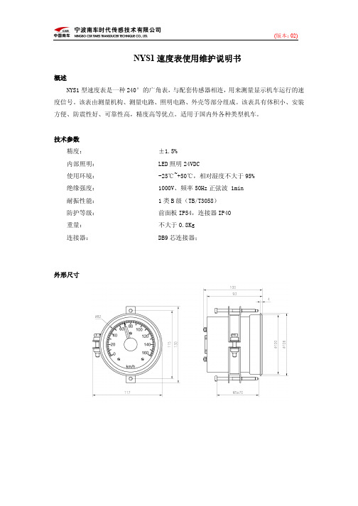
NYS1型速度表是一种240°的广角表,与配套传感器相连,用来测量显示机车运行的速度信号。
该表由测量机构、测量电路、照明电路、外壳等部分组成。
该表具有体积小、安装方便、防震性好、可靠性高,精度高等优点。
适用于国内外各种类型机车。
技术参数
精度: ±1.5%
内部照明: LED照明24VDC
使用环境: -25℃~+50℃,相对湿度不大于95%
绝缘强度: 1000V、频率50Hz正弦波 1min
耐振性能: 1类B级(TB/T3058)
防护等级: 前面板IP54,连接器IP40
重量: 不大于0.8Kg
连接器: DB9芯连接器;
外形尺寸
接线图
安装与使用
1、安装采用轭箍式支架,安装表头的开孔尺寸Φ101mm。
2、使用时观察表头额定值,照明电压值应与订货相符。
3、速度表配线按照接线图配线,确保正确无误(照明接到信号输入端,会打坏表头),表头指针、照明都有极性要求。
电缆屏蔽层接表外壳接地片上。
校验与检修
■如需调整线性误差,先将底部橡皮塞取下,用螺丝刀调整表内电位器,使其达到规定值。
■指针零位变化,或者偏差无法调节,照明损坏,请不要打开,并送制造厂维修。
■使用过程中应避免频繁过载及长时间过载。
摩托车仪表控制设备手册说明书
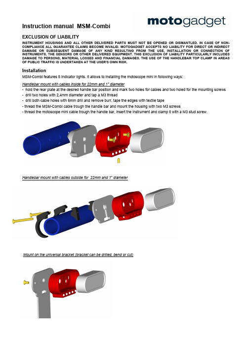
Instruction manual MSM-CombiEXCLUSION OF LIABILITYINSTRUMENT HOUSINGS AND ALL OTHER DELIVERED PARTS MUST NOT BE OPENED OR DISMANTLED. IN CASE OF NON-COMPLIANCE ALL GUARANTEE CLAIMS BECOME INVALID. MOTOGADGET ACCEPTS NO LIABILITY FOR DIRECT OR INDIRECT DAMAGE OR SUBSEQUENT DAMAGE OF ANY KIND RESULTING FROM THE USE, INSTALLATION OR CONNECTION OF INSTRUMENTS, THE SENSORS OR OTHER DELIVERED EQUIPMENT. THIS EXCLUSION OF LIABILITY PARTICULARLY INCLUDES DAMAGE TO PERSONS, MATERIAL LOSSES AND FINANCIAL DAMAGES. THE USE OF THE HANDLEBAR TOP CLAMP IN AREAS OF PUBLIC TRAFFIC IS UNDERTAKEN AT THE USER'S OWN RISK.InstallationMSM-Combi features 5 indicator lights. It allows to installing the motoscope mini in following ways:Handlebar mount with cables inside for 22mm and 1" diameter- hold the rear plate at the desired handle bar position and mark two holes for cables and two holed for the mounting screws- drill two holes with 2,4mm diameter and tap a M3 thread- drill both cable holes with 6mm drill and remove burr, tape the edges with textile tape- thread the MSM-Combi cable trough the handle bar and mount the housing with two M3 screws- thread the motoscope mini cable trough the handle bar, insert the instrument and clamp it with a M3 stud screw.Handlebar mount with cables outside for 22mm and 1" diameterMount on the universal bracket (bracket can be drilled, bend or cut)Installation with a weld-in-housing for a fuel tank integration- weld a stainless steel tube (inner dia. 10mm, leght = fuel tank height) at the cable outlet on the backside of the weld-in-housing.- make a cut out in the shape of the weld-in-housing at the topside of the fuel tank.- drill a hole with diameter of the steel tube in the opposite fuel tank bottom- weld the weld-in-housing together with the cut out at the fuel tank- weld the tube with the hole at the bottom side- check the leak tightness / paint- mount the MSM-Combi housing into the weld-in-housing by two M3 screws- thread the motoscope cable trough the tube and install the instrument with a small amount of silicone rubber into the weld-in-housingElectrical connectionRemove the vehicle battery before continuing the electrical wiring or interrupt the connection to the onboardpower supply. Then connect the warning lights as follows:cable color function polarity red turn left +12V blue MIL / ABS +12V orange turn earth Masse green high beam +12V yellow high beam Masse white neutral +12V black neutral Masse brown oil pressure +12V violett oil pressure MasseDeclaration of ConformityHereby, motogadget GmbH declares the product is in compliance to EU directives.The full text of the EU Declaration of Conformity is available at the following internet address: https:///motoscope-mini-combiframe。
Acura CL 2.2CL和3.0CL机车维护指南说明书

engine, and let it run until it warms up (the radiator cooling fan comes on at least twice).10. Turn off the engine. Check thelevel in the radiator, and add coolant if needed. Install the radiator cap, and tighten it fully.11. Fill the reserve tank to theM A X mark. Install the reserve tank cap.Windshield WashersCheck the level in the windshield washer reservoir at least monthly during normal usage. In bad weather, when you use the washers often, check the level every time you stop for fuel.The windshield washer reservoir is located behind the driver's side headlight on the 2.2CL, and behind the passenger's sideheadlight on the 3.0CL. Check the reservoir's fluid level by removing the cap and looking at the dipstick.Fill the reservoir with agood-quality windshield washer fluid. This increases the cleaning capability and prevents freezing in cold weather.Do not use engine antifreeze or a vinegar/water solution in the windshield washer reservoir.Antifreeze can damage your car's paint, while avinegar/water solution can damage the windshield washer pump.Use only commercially available windshield washer fluid.MaintenanceNOTICERESERVE TANKLEVEL GAUGETransmission FluidAutomatic TransmissionCheck the fluid level with the engine at normal operating temperature.1. Park the car on level ground.Shut off the engine.2. Remove the dipstick (yellowloop) from the transmission,and wipe it with a clean cloth.3. Insert the dipstick all the wayinto the transmission securely as shown in the illustration.4. Remove the dipstick andcheck the fluid level. It should be between the upper and lower marks.5. If the level is below the lowermark, add fluid into the tube to bring it to the upper mark.Always use Honda Premium Formula AutomaticTransmission Fluid (ATF). If it is not available, you may use a Dexron III automatic transmission fluid as a temporary replacement.However, continued use canMaintenance2.2CL DIPSTICKDIPSTICKUPPER MARK LOWER MARK3.0CLaffect shift quality. Have the transmission drained and refilled with Honda ATF as soon as it is convenient.6. Insert the dipstick all the wayback in the transmission.Make sure that the notch fits in the dipstick guide and the dipstick is all the way down.The transmission should be drained and refilled with new fluid according to the time and distance recommendations in the maintenance schedule.5-Speed Manual TransmissionCheck the fluid level with the transmission at normal operating temperature and the vehicle sitting on level ground. Remove thetransmission filler bolt and carefullyfeel inside the bolt hole with your finger. The fluid level should be up to the edge of the bolt hole. If it is not, add Genuine Honda Manual Transmission Fluid (MTF) until it starts to run out of the hole.Reinstall the filler bolt and tighten it securely.If Honda MTF is not available,you may use an API Service SG or SH-grade motor oil with aviscosity of 10W-30 or 10W-40 as a temporary replacement.However, motor oil does not contain the proper additives and continued use can cause stiffer shifting. Replace as soon as convenient.The transmission should bedrained and refilled with new oil according to the time and distance recommendations in the maintenance schedule.MaintenanceFILLER BOLTCORRECT LEVEL。
摩托车仪表部件的相关使用
摩托车仪表部件的相关使用在摩托车上,仪表部件是连接驾驶员与车辆的重要环节,提供了车速、转速、油量、水温等各种信息。
了解这些仪表部件的使用方法和功能,可以帮助驾驶员更好地掌握车辆状态,从而提高行车安全。
速度计速度计是摩托车上最常用的仪表部件之一,用于显示当前车速。
驾驶员应该在行驶时时刻关注速度计,并且注意保持合适的行驶速度。
同时,速度计也可以用来控制车速,帮助驾驶员维持一定的行驶速度。
转速计旋转计可以显示引擎的转速,从而帮助驾驶员了解发动机的状态。
在启动车辆时,应该先将车辆预热几分钟,然后使用低速档行驶,等引擎逐渐升温后再加大油门。
此外,在长时间停车后重新起动车辆时,也应该谨慎使用油门,以避免引擎受损。
油量计油量计是显示油箱中剩余油量的仪表部件,用于帮助驾驶员及时加油以避免燃料不足。
驾驶员应该经常检查油量计,以确保车辆有足够的燃料供应。
当车辆提示油量过低时,应该及时前往加油站加油。
水温计水温计是显示发动机水温的仪表部件,用于帮助驾驶员监控发动机的温度。
驾驶员应该经常检查水温计,以确保发动机运行在适宜的温度范围内。
水温过高时,应该立即停车检查发动机,以避免损坏发动机。
车灯指示器车灯指示器可以显示车辆灯光的状态,帮助驾驶员了解灯光是否正常工作。
驾驶员应该在行驶时经常检查车灯指示器,以确保灯光正常亮起。
当车灯指示器提示灯光异常时,应该立即寻找故障原因并进行维修。
总结了解摩托车仪表部件的使用方法和功能,可以帮助驾驶员更好地保护和驾驶车辆。
驾驶员应该经常检查各种仪表,确保其正常工作,并及时进行维护和保养。
除此之外,驾驶员也应该注意安全,遵守交通规则,降低行车风险。
- 1、下载文档前请自行甄别文档内容的完整性,平台不提供额外的编辑、内容补充、找答案等附加服务。
- 2、"仅部分预览"的文档,不可在线预览部分如存在完整性等问题,可反馈申请退款(可完整预览的文档不适用该条件!)。
- 3、如文档侵犯您的权益,请联系客服反馈,我们会尽快为您处理(人工客服工作时间:9:00-18:30)。
3/8 3/8a型机车速度表使用维护说明书
版本:第1.0版
修改记录
版本号更改日期更改的主要原因更改的章节与内容
1.0 2009-04-30 编制全部
目录
1 功能及用途错误!未指定书签。
2 说明错误!未指定书签。
2.1技术参数错误!未指定书签。
2.2结构及技术说明错误!未指定书签。
2.3工作原理错误!未指定书签。
3 安全说明错误!未指定书签。
4 使用操作错误!未指定书签。
5 安装和调试错误!未指定书签。
5.1安装错误!未指定书签。
5.2调试错误!未指定书签。
6维修错误!未指定书签。
6.1维修等级错误!未指定书签。
6.2维修计划错误!未指定书签。
6.3维护工作错误!未指定书签。
6.4修正工作错误!未指定书签。
7 故障处理、更换原则与维修错误!未指定书签。
7.1故障处理错误!未指定书签。
7.2拆卸错误!未指定书签。
7.3更换原则错误!未指定书签。
7.4拆解错误!未指定书签。
7.5维修错误!未指定书签。
7.6组装错误!未指定书签。
7.7重新安装错误!未指定书签。
7.8参数设置与限度表错误!未指定书签。
7.9投入使用/功能试验错误!未指定书签。
8 专用工具及设备、易损件及备件清单错误!未指定书签。
8.1专用工具错误!未指定书签。
8.2设备错误!未指定书签。
8.2.1 化学清洗剂错误!未指定书签。
8.2.2 涂层成分错误!未指定书签。
8.2.3 润滑剂错误!未指定书签。
8.2.4 其它设备错误!未指定书签。
8.3测量和试验设备错误!未指定书签。
8.4易损件及备件清单错误!未指定书签。
8.5运用材料错误!未指定书签。
9 废弃物处理方案错误!未指定书签。
10 运输与贮存错误!未指定书签。
10.1运输错误!未指定书签。
10.2贮存错误!未指定书签。
11 零件目录及备件采购错误!未指定书签。
11.1零件目录错误!未指定书签。
11.2备件的仓储及采购错误!未指定书签。
12 开箱及检查错误!未指定书签。
13 其他错误!未指定书签。
14 缩写和索引错误!未指定书签。
1 功能及用途
3/8 3/8a双针表是上海德意达公司( )引进德国公司全套技术组装生产的广角度仪表。
3/8为双针表带里程,3/8a为双针表。
该表由上、下机芯、里程计及外壳组成,具有结构牢固、防震性好、寿命长等特点。
适用于国内外各种类型的机车,可用于直观地显示机车运行速度和机车累计走行距离。
2 说明
2.1 技术参数
2.1.1. 精度: 1.5%
2.1.2.测速范围:0-160km/h
2.1.
3. 表头额定值:0-20
2.1.4. 内部照明:24V 2×3W
2.1.5.里程累计:7位,最大9,999,999,24V 15(脉冲持续时间≥150)
2.1.6. 绝缘强度:500V,50 交流正弦值1
2.1.7. 工作温度:-25~+70℃
2.1.8. 耐振性能:1g,100 ( 89011)
2.1.9. 重量:1.15
2.2 结构及技术说明
照 明 (Illumination)
编 码 (Code number)参 数 (Parameter)0-160km/h 0-20mA DC24V 3W
01903808
名 称图纸代号号
件货品代号
10532146798
1211131417
16151819I1938·00·05电位器标记
I1938·00·04I1938·00·02I1938·00·08I1938·00·09I1938·00·10I1938·00·11I1903B ·01·00
橡皮塞DIN546
尼龙密封圈封壳圈24灯泡标记
3/8接线标记带槽圆螺母
遮光环灯座表芯组装
外壳衬圈夹箍组装玻璃泡沫橡皮圈外壳组装I1903B ·02·00灯泡3
I1938·00·12I1903B ·00·01B/I1903.104EGZ3/8az速度表标贴
I1903·00·03接地标记
B/I1938·157
接线标签放大图:
接线图:
里程计
外针内针
照明
照明
.
(定义)
(照明线号)
24V +
24V-
2.3 工作原理
3/8 3/8a双针表的基本原理是:速度表将由外部设备产生的、与速度成正比的电流信号送入速度表线圈,通电线圈在磁场中受到电磁作用力产生转动力矩驱动速度表指针。
3 安全说明
表3-1
危险
警告
切忌将照明电压误接到速度表信号输入端,以免造成损坏。
注意
该仪表属精密仪表,不能承受剧烈振动和冲击,在搬运、安装、拆卸时,注意保护,
否则容易造成玻璃破碎、指示不准,甚至损坏。
注意
该仪表应存放在通风、干燥、无化学腐蚀性气体,建议储存温度-20~50度,湿度
小于85%,尤其在长期储存时,更应注意,否则会造成内部部件的锈蚀,影响仪表
性能,甚至损坏。
表3-2 安全拧紧转矩表
拧紧位置螺纹公称尺寸拧紧转矩() 扳手尺寸备注
夹箍固定M6 8.5 套筒或一字
将夹箍固定在仪表上
螺丝刀
速度表固定M5 4.8 十字螺丝刀安装在司机控制台仪
表板上
4 使用操作
表4-1 操作及操作控制步骤
5 安装和调试
5.1 安装
表5-1 安装步骤
5.2 调试
表5-2 调试前的检查步骤
表5-3 调试及退出调试步骤
6 维修
6.1 维修等级
表6-1 维修等级
6.2 维修计划
表6-2 维修计划
6.3 维护工作
表6-3 维护
6.4修正工作
表6-4 修正
7 故障处理、更换原则与维修
7.1 故障处理
表7-1 故障分析与处理
7.2 拆卸
表7-2 拆卸
7.3 更换原则
7.4 拆解
7.5 维修
表7-3 维修
7.6 组装
表7-4 组装
7.7 重新安装
表7-5 重新安装
7.8 参数设置与限度表
7.9 投入使用/功能试验
8专用工具及设备、易损件及备件清单
表8-1(注:编制时保留此表)
8.1 专用工具
表8-2 专用工具
8.2 设备
8.2.1 化学清洗剂
8.2.2 涂层成分
表8-4 涂层组成
8.2.3 润滑剂
8.2.4 其它设备
表8-6 其它设备
8.3 测量和试验设备
表8-7 测量和试验设备
8.4 易损件及备件清单
表8-8 易损件及备件清单
8.5 运用材料
9 废弃物处理方案
表9-1 废弃物处理方法
10 运输与贮存
10.1 运输
双针速度表属精密仪表,尽管有较好的抗振包装,但一般堆放高度不宜太高,运输过程中,尽量存放在防水、防油、无化学腐蚀性气体的环境中,建议储存温度范围,-20~50度,湿度小于85%。
10.2 贮存
室内储存:室内通风、干燥、无化学腐蚀性气体,建议储存温度范围,-20~50度,湿度小于85%。
11 零件目录及备件采购
11.1 零件目录
表11-1 仪表外配线零件清单
11.2备件的仓储及采购
表11-2 部件备件的仓储及采购
12 开箱及检查
13 其他
14 缩写和索引
要求:列出本使用维护说明书中所使用的缩写词的全称和索引。