7-24C
集成电路型号
AN1452 音频前置放大集成电路
9 H0 ]& m& n Q6 I& y* Q* }+ ]9 G/ C7 i0 xAN1458S 双运算放大集成电路: X1 E' F3 g" F+ b' v
28F004 版本集成电路9 b& j0 N) S I
32D54 电源、音频信号处理集成电路
2 D% [/ c) H. A% @) w32D75 电源、音频信号处理集成电路
0 H) j+ b- i* g1 R$ y; z32D92 电源中频放大集成电路 G/ [3 H4 ?' ^! T9 k& X
0 r% e2 ?. L' C: u" Y: S3 Z; LAN253P 调频/调幅中频放大集成电路
! S0 y) r' |+ r- t/ eAN262 音频前置放大集成电路8 W( F4 y" g5 X- \6 U6 l! P
AN2661NK 视频信号处理集成电路% d( y2 u- I% J8 \* D: d8 w
0 r4 q1 s! [1 S* l8 l27C2000QC-90 存储集成电路
) L/ u, }6 m, Q27C20T 存储集成电路/ m& N, N6 f1 v+ @+ V
27C512 电可改写编程只读存储集成电路
; F4 y' w9 z% x! [28BV64 码片集成电路( g0 k% O- @' F7 `( K8 O
Eeprom的读写
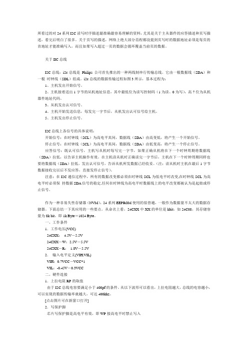
所看过的对24系列I2C读写时序描述最准确最容易理解的资料,尤其是关于主从器件的应答描述和页写描述,看完后明白了很多。
关于页写的描述,网络上绝大部分范程都没提到页写时的数据地址必须是每页的首地址才能准确写入,而且如果写入超过一页的数据会循环覆盖当前页的数据。
关于IIC总线I2C总线:i2c总线是Philips 公司首先推出的一种两线制串行传输总线。
它由一根数据线(SDA)和一根时钟线(SDL)组成。
i2c总线的数据传输过程如图3所示,基本过程为:1、主机发出开始信号。
2、主机接着送出1字节的从机地址信息,其中最低位为读写控制码(1为读、0为写),高7位为从机器件地址代码。
3、从机发出认可信号。
4、主机开始发送信息,每发完一字节后,从机发出认可信号给主机。
5、主机发出停止信号。
I2C总线上各信号的具体说明:开始信号:在时钟线(SCL)为高电平其间,数据线(SDA)由高变低,将产生一个开始信号。
停止信号:在时钟线(SCL)为高电平其间,数据线(SDA)由低变高,将产生一个停止信号。
应答信号:既认可信号,主机写从机时每写完一字节,如果正确从机将在下一个时钟周期将数据线(SDA)拉低,以告诉主机操作有效。
在主机读从机时正确读完一字节后,主机在下一个时钟周期同样也要将数据线(SDA)拉低,发出认可信号,告诉从机所发数据已经收妥。
(注:读从机时主机在最后1字节数据接收完以后不发应答,直接发停止信号)。
注意:在I2C通信过程中,所有的数据改变都必须在时钟线SCL为低电平时改变,在时钟线SCL为高电平时必须保持数据SDA信号的稳定,任何在时钟线为高电平时数据线上的电平改变都被认为是起始或停止信号。
作为一种非易失性存储器(NVM),24系列EEPROM使用的很普遍,一般作为数据量不太大的数据存储器。
下面总结一下其应用的一些要点。
从命名上看,24CXX中XX的单位是kbit,如24C08,其存储容量为8k bit,即1k Byte=1024 Byte。
EEPROM存储芯片24C02
EEPROM存储芯⽚24C021、24C02简介 24C02是⼀个2Kbit的串⾏EEPROM存储芯⽚,可存储256个字节数据。
⼯作电压范围为1.8V到6.0V,具有低功耗CMOS技术,⾃定时擦写周期,1000000次编程/擦除周期,可保存数据100年。
24C02有⼀个16字节的页写缓冲器和⼀个写保护功能。
通过I2C总线通讯读写芯⽚数据,通讯时钟频率可达400KHz。
可以通过存储IC的型号来计算芯⽚的存储容量是多⼤,⽐如24C02后⾯的02表⽰的是可存储2Kbit的数据,转换为字节的存储量为2*1024/8 = 256byte;有⽐如24C04后⾯的04表⽰的是可存储4Kbit的数据,转换为字节的储存量为2*1024/8 = 512byte;以此来类推其它型号的存储空间。
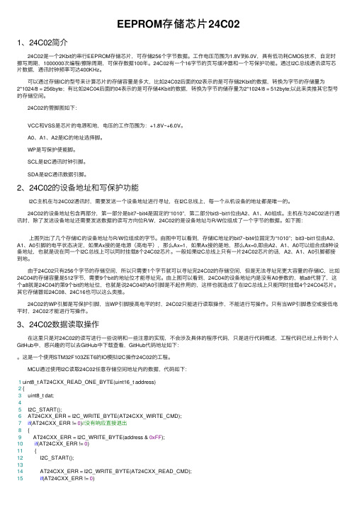
24C02的管脚图如下: VCC和VSS是芯⽚的电源和地,电压的⼯作范围为:+1.8V~+6.0V。
A0、A1、A2是IC的地址选择脚。
WP是写保护使能脚。
SCL是I2C通讯时钟引脚。
SDA是I2C通讯数据引脚。
2、24C02的设备地址和写保护功能 I2C主机在与24C02通讯时,需要发送⼀个设备地址进⾏寻址,在I2C总线上,每⼀个从机设备的地址都是唯⼀的。
24C02的设备地址包含两部分,第⼀部分是bit7~bit4是固定的“1010”,第⼆部分bit3~bit1位由A2、A1、A0组成。
主机在与24C02进⾏通讯时,除了发送设备地址还需要发送数据的读写⽅向位R/W,24C02的是设备地址与R/W位组成了⼀个字节的数据。
如下图: 上图列出了⼏个存储IC的设备地址与R/W位组成的字节。
由图中可以看到,存储IC地址的bit7~bit4位固定为“1010”;bit3~bit1位由A2、A1、A0引脚的电平状态决定,如果Ax接的是电源(⾼电平),那么Ax=1,如果Ax接的是地,那么Ax=0,即由A2、A1、A0可以组合成8种设备地址,也就是说在同⼀个I2C总线上可以同时挂载8个24C02芯⽚。
工程成本练习题第七章
第七章工程项目招投标阶段的成本规划与控制一、单项选择题7-1 投标文件不响应()和条件的,招标人应当拒绝。
不允许投标人通过修正或撤销,使之成为具有响应性的投标。
A. 招标文件的技术性要求B. 招标文件的实质性要求C. 招标文件的格式化要求D. 招标文件的保密性要求7-2 根据《招投标法》和国家计委的有关规定,使用国际组织或者国外政府贷款、援助资金的项目,其重要设备、材料的采购,项目总投资额在()万元人民币以上的,必须进行招标。
A. 5000B. 8000C.3000 D. 10007-3 经过审批部门批准应当采用邀请招标方式招标的是()。
A. 涉及国家安全而不适宜招标的项目B. 施工企业自建自用工程,且该施工企业资质等级符合工程要求的项目C. 拟公开招标的费用与项目的价值相比,不值得公开招标的项目D. 在建工程追加的附属小型工程,原中标人仍具备承包能力的项目7-4 施工企业投标报价的主要依据是()。
A. 企业定额B.地方定额C. 行业定额D.国家定额7-5 采用估计工程量单价合同时,最后工程的总价是按( )计算确定的。
A. 业主提出的暂估工程量清单及承包商所填报的单价B. 业主提出的暂估工程量清单及其实际发生的单价C. 实际完成的工程量及承包商所填报的单价D. 实际完成的工程量及其实际发生的单价7-6 采用可调值总价合同,发包方承担()的风险。
A. 工程量因素B.通货膨胀因素C. 工期因素D.成本因素7-7 不可调不变总价合同一般适用于()工程。
A. 工期短于1年B. 工期大于1年C. 工程价值小于100万元D. 工程价值大于100万元7-8 没有施工图,工程量不明,却急需开工的紧迫工程应采用()合同。
A. 估算工程量单价B. 纯单价C. 不可调值总价D. 可调值总价7-9 在按成本加酬金确定合同价时,最不利于降低成本的是()。
A. 成本加固定百分比B. 成本加固定金额C. 成本加奖罚金D. 成本加固定利润7-10 以下关于成本补偿合同的特点表述中,错误的是()。
常用存储器的代换对照

常用存储器的代换对照存储器, 代换PCA8581=24C01PCA8582=24C02PCE8522EP=24C02PCF8594C-2=24C04PCF8598C=24C08A510C=24C08(直接代换)代换时注意第7脚的状态,一般24C系列7脚都是接地的。
存储器24C04在彩电中运用广泛,目前大多数品牌彩电均选用它的系列型号作为存储器,其系列型号为:24C0l、24C02、24C04、24C08、24C16、24C32等等。
根据不同的制造厂商,在它们的前面冠以不同的字母,如AT、ST、BR、SL、KOR、KS等。
它们之间代换时,重点对⑦脚进行改接。
存储器24C04引脚功能与参数见表7。
存储器24C04的特点:(1)存储容量大,有4000bit,可存储100套电视节目(注:24C02存储60套,24C08存储200套);(2)外围电路简洁,内部设计有I2C接口电路,很方便地通过数据线与CPU连接,实现I2C总线控制,提高整机的工作性能;(3)工作电压范围宽2.5~6.8V,当电压为6V时写入峰值电流为3mA,最大读取电流150μP,待机时电流1μA左右,典型工作电压为5V左右;(4)内部设计有数据写入保护电路;(5)断电后内部数据可保存80年以上;(6)有噪音抑制功能,采用施密特触发器。
更换存储器24C04应注意:1.长虹2918FN彩电中,24C04典型连接图如图6所示。
图62.当微处理器及外围电路正常后需要更换存储器,只能用尾数大于或等于的型号代换,否则会造成存储节目数量减少,有的会造成某些功能失常等。
3.更换24C04系列存储器时,必须注意该存储器的制造商及电路板上⑦脚的接法。
24CXX系列存储器⑦脚的功能有:写保护控制(Wt))、取消写保护控制。
当⑦脚为低电平时,即⑦脚接地.为取消写保护控制。
这时微处理器通过总线写入需要存储的数据.完成存储,制造商有AT、ST、BR等生产的24CXX系列存储器:当⑦脚为高电平时,即⑦脚通过一只10kΩ上拉电阻至5V电眍,处于写保护状态,如果是.AT、ST、BR等厂商的24CXX系列存储器不能存入数据,KOR、KS等韩国厂商的24CXX系列存储器却能写入数据存储。
24C02中文资料
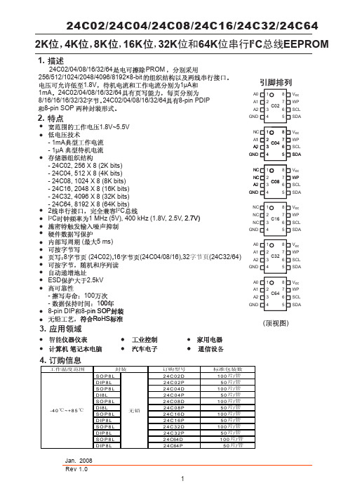
24C02/24C04/24C08/24C16/24C32/24C641.2.2K4K 8K ,16K ,32K 位和64K 位串行I C 总线EEPROM3.24C02/04/08/16/32/64PROM256/512/1024/2048/4096/8192×8-bit1.8V1μA1mA 24C02/04/08/16/32/648/16/16/16/32/3224C02/04/08/16/32/648-pin PDIP8-pin SOP ●●●●●●●●●●●●SD SCL WP V CC NC A SD A SCL WP V CC 12348765NC NC NC GND SD A SCL WP V CC 12348765 ()SD A SCL WP V CC 12348765A 0A 1A 2GND C02C1621.8V~5.5V- 1mA- 1μA- 24C02, 256 X 8 (2K bits)- 24C04, 512 X 8 (4K bits) - 24C08, 1024 X 8 (8K bits) - 24C16, 2048 X 8 (16K bits)- 24C32, 4096 X 8 (32K bits)- 24C64, 8192 X 8 (64K bits)2I CI C 1 MHz (5V), 400 kHz (1.8V, 2.5V, 2.7V) ( 5 ms)8 (24C02)16(24C04/08/16),32字节页(24C32/64)ESD 2.5kV - 100- 100 8-pin DIP 8-pin SOP RoHS ●●●●●●●22●S D A 123487651A 2GND NC NC C A 2GND C04C082.7V)00n SOP●●SD A SCL WP V CC 12348765A 0A 1A 2GND C32SD ASCL WP V CC 12348765A 0A 1A 2GNDC6424C02/24C04/24C08/24C16/24C32/24C645. Ḛ1 ḚV 6. 乱 ヺ ԡⳈ⌕կ⬉⬉ Ⳉ⌕䕧 ⬉ ⏽V CC Ⳉ⌕䕧 ⬉ V IN V OUT T STG -0.3 ~ V CC +0.3-0.3 ~ V CC +0.3-0.3 ~ +6.5°C -65 ~ +150V °C7. 㤤 ӊヺ ԡⳈ⌕կ⬉⬉ V CC ⏽T A+855.5 1.8-40(䍙 乱 㛑Ӯ 㟈 ӊ )V V ( 㤤 ӊϟ ⦄ 㛑)SDASCL WP V CCNC /NC /NC /A0NC /NC /A1/A1NC /A2/A2/A2C16/C08/C04/C02GNDSTART STOPLOGICSERIAL CONTROLLOGICDEVICE ADDRESS COMPARATORDATA WORD ADDRESS COUNTER LOADCOMPLOADINCY DECODER HIGH VOLTAGE PUMP/TIMING ENDATA RECOVERYEEPROMSERIAL MUXX D E C O D E RDOUT/ACKNOWLEDGEDINESD ⬉ (Ҏԧ )ESD ⬉ ( )V ESD2500200V V乱⬉ 䕧 ⬉ 乱 㛑Ӯ 㟈 ӊ DOUTmA 9. Ⳉ⌕⬉⇨⡍ヺ ԡ ⬉⌕կ⬉⬉⌕I CC V CC =5V⌟䆩 ӊ100kHz 3.0䕧 Ԣ⬉ ⬉μA 3.01.0-0.6V 0.4V IN = V CC GND 0.05( ӊ˖T A = 0°C ̚ +70°C, V CC = +1.8V ̚ +5.5V ˈ䰸䴲 ⊼䞞)䕧 Ԣ⬉ ⬉ μA V IL 0.4V CC0.20.4100kHz V V CC ×0.3I SB V IN = V CC GND V OUT = V CC GND μA 䕧 ⓣ⬉⌕䕧 ⓣ⬉⌕I LI I LO V IH 䕧 催⬉ ⬉ V CC +0.5V V V VV OL3V OL2V = 2.1 mA V 10. Ѹ⌕⬉⇨⡍ ( ӊ˖T A = 0°C ̚ +70°C, V = +1.8V +5.5V, C L = 100 pF ˈ䰸䴲 ⊼䞞)ヺ ԡ䩳催⬉䩳乥⥛, SCL ⌟䆩 ӊ400V CC =1.8V 1000ns 0.050.050.60.90.6 μskHz 1.20.5540V CC =5V 0.4t LOW μs ⍜䰸 䯈 䩳ϟ䰡⊓ 䕧 䯈䱨 䯈t I t AA50t HIGH䩳Ԣ⬉ μsV CC =1.8V V CC =5V V CC =1.8V V CC =5V V CC =1.8V V CC =5V V CC =1.8V V CC =5V8. 㛮⬉( ӊ˖T A = 25°C, f = 1.0 MHz, V CC = +1.8V)pFヺ ԡ䕧 /䕧 ⬉ (SDA)C I/O 䕧 ⬉ (A0, A1, A2, SCL)C IN68 pF⌟䆩 ӊV I/O = 0V V IN = 0V1.2 㒓䞞 䯈t BUF0.5μs V CC =1.8V V CC =5V䇏1.03.0 mA m 042.0C =5.0V, I OL = 3.0 mA CC ×0.7GNDOL1V CC =3.0V, I OL =2.1mA CC =1.8V, I OL = 0.15 mA =C CC = +1.8V ̚+5.5f SCL10. Ѹ⌕⬉⇨⡍ (㓁)䕧 Ϟ 䯈 䕧 䯈0ns500.650.25ns t WRns 100ns ℶ ӊ ゟ 䯈 䕧 䯈t R t DH t F 䕧 ゟ 䯈μs ms䕧 ϟ䰡 䯈t SU.STOV CC =1.8V V CC =5V V CC =1.8V V CC =5Vμs 300100300t HD.DAT t SU.DAT 2 㒓3SCLSDA_INSDA _OUTt F t LOWt SU .STAt HD.STAt AA t DHt BUFt SU.STOt Rt HD.DAT t SU.DAT t HIGH t LOW8th BIT SCLSDAACKSTOPCONDITIONSTART CONDITIONt WR (1)t HD.STAμs 䍋 ӊ 䯈䍋 ӊ ゟ 䯈t SU.STA V CC =1.8V V CC =5V V CC =1.8V V CC =5Vμs 0.60.250.60.25ヺ ԡ ⌟䆩 ӊ ⊼ 䯈W :5 ҢϔϾ ⱘ ℶ ӊ 㟇 䚼 㒧 ⱘ 䯈DŽn 08V μ3001AHIG11.3156247A0A1A2SDA SCL WP GND V CCA2A1A024C02/32/64A2A1A0824C02/32/6424C04A2A1424C04A024C08A2224C08A0A124C1616KA2A1A0/SDA V CC10kΩSCL8WP WPWPV CC12.13. 䆺㒚 䇈24CXX I C 㒓Ӵ䕧 䆂DŽI C ϔ⾡ ǃϸ㒓І㸠䗮䆃 ˈ І㸠 㒓SDA І㸠 䩳㒓SCL DŽϸḍ㒓䛑 乏䗮䖛ϔϾϞ ⬉䰏 ⬉⑤DŽ ⱘ 㒓䜡㕂 4 ⼎4 ϸ㒓 㒓䜡㕂㒓Ϟ 䗕 ⱘ ӊ㹿⿄ 䗕 ˈ ⱘ ӊ㹿⿄ DŽ Ѹ ⱘ ӊ㹿⿄Џ ӊˈ Џ ӊ ⱘ ӊ 㹿⿄Ң ӊDŽЏ ӊѻ⫳І㸠 䩳SCL ˈ㒓ⱘ䆓䯂⢊ ǃѻ⫳START STOP ӊDŽ24CXX I C 㒓ЁЎҢ ӊ DŽ㒓 Ѣぎ䯆⢊ ҹ Ӵ䕧DŽ↣ Ӵ䕧 ѢSTART ӊˈ㒧 ѢSTOP ӊˈѠ㗙П䯈ⱘ 㡖 ≵ 䰤 ⱘˈ⬅ 㒓ϞⱘЏ ӊ DŽ ҹ 㡖˄8ԡ˅Ў ԡӴ䕧ˈ9ԡ ⬅ ѻ⫳ ㄨDŽ䍋 ℶ ӊ䩳㒓䛑Ў催 ⿄ 㒓 ぎ䯆⢊ DŽ SCL Ў催⬉ SDA ⱘϟ䰡⊓˄催 Ԣ 䍋 ӊ˄START ˈㅔ ЎS ˅ˈSDA ⱘϞ ⊓˄Ԣ 催˅ ℶ ӊ˄STOP ˈㅔ ЎP ˅DŽ 㾕 5DŽ5 䍋 ӊ ℶ ӊⱘ НV CCҪ24Cxx MPU SDASCLR PR Pϸ㒓І㸠S Ў催ㅔ ЎⱘϞ ⊓˄Ԣ 㒓І㸠 㒓SS 䍋 ӊ222ԡӴ䕧↣Ͼ 䩳㛝 Ӵ䗕ϔԡ DŽSCL Ў催 SDA 乏 〇 ˈ Ўℸ SDA ⱘ 㹿䅸Ў DŽԡӴ䕧 㾕 6DŽ6 ԡӴ䕧ㄨ㒓Ϟⱘ ↣ ϔϾ 㡖 ѻ⫳ϔϾ ㄨˈЏ ӊ 乏ѻ⫳ϔϾ ⱘ乱 ⱘ 䩳㛝 ˈ㾕 7DŽ7 I C㒓ⱘ ㄨ ԢSDA 㒓㸼⼎ ㄨˈ ㄨ㛝 䯈 〇 ⱘԢ⬉ DŽ Џ ӊ ˈ 乏 Ӵ䕧㒧 ⱘ 㒭 䗕 ˈ ϔϾ 㡖П ⱘ ㄨ㛝 䯈ϡӮѻ⫳ ㄨ ˄ϡ ԢSDA ˅DŽ䖭⾡ ϟˈ 䗕 乏䞞 SDA 㒓Ў催ҹ Џ ӊѻ⫳ ℶ ӊDŽ䗕 䕧 ⱘ䕧 ⱘЏ ӊ ⱘ䍋 ӊ289䴲 ㄨㄨㄨ 䩳㛝㒓〇䆌SDASCL2ѻ⫳ϔϾ ㄨˈЏ ӊ 乏ѻ⫳ϔԢ㒓Ӵӊ ⱘSCL 䍋 ӊS1ӊ䍋 ӊՓ㛑㢃⠛䇏 ˈEEPROM 䛑㽕∖ 8ԡⱘ ӊ ˄㾕 8˅DŽӊ ⬅"1"ǃ"0" 㒘 ˈ 4ԡ Ё ⼎ˈ Ѣ І㸠EEPROM 䛑 ϔḋⱘ Ѣ24C02/32/64ˈ䱣 3ԡA2ǃA1 A0Ў ӊ ԡˈ 乏Ϣ⹀ӊ䕧 㛮 ϔ㟈DŽ Ѣ24C04ˈ䱣 2ԡA2 A1Ў ӊ ԡˈ 1ԡЎ义 ԡDŽA2 A1 乏Ϣ⹀ӊ䕧 㛮 ϔ㟈ˈ㗠A0 ぎ㛮DŽѢ24C08ˈ䱣 1ԡA2Ў ӊ ԡˈ 2ԡЎ义 ԡDŽA2 乏Ϣ⹀ӊ䕧 㛮 ϔ㟈ˈ㗠A1 A0 ぎ㛮DŽѢ24C16ˈ ӊ ԡˈ3ԡ䛑Ў义 ԡˈ㗠A2ǃA1 A0 ぎ㛮DŽ ӊ ⱘLSB Ў䇏/ 䗝 ԡˈ催Ў䇏 ˈԢЎ DŽ㢹↨䕗 ӊ ϔ㟈ˈEEPROM 䕧 ㄨ"0"DŽ ϡϔ㟈ˈ 䖨 ⢊ DŽ8 ӊ 1010A2A1A0R/W MSBLSB1010A2A1P0R/W1010A2P1P0R/W1010P2P1P0R/Wӊ EEPROM Ԣ 㗫 ⱘ⡍⚍ˈ ӊЎ˖˄1˅⬉⑤Ϟ⬉˗˄2˅ ℶ ӊ ӏԩ 䚼 DŽ24C0424C0824C16DŽ ԡ䆂Ёѻ⫳Ё ǃ ⬉ ㋏㒳 ԡ ˈI C 㒓 䗮䖛ҹϟℹ偸 ԡ˖ ˄1˅ѻ⫳9Ͼ 䩳 DŽ˄2˅ SCL Ў催 ˈSDA гЎ催DŽ ˄3˅ѻ⫳ϔϾ䍋 ӊDŽ21. 㡖㽕∖ ӊ ACK ㄨ ˈ 8ԡⱘ DŽ 䖭Ͼ EEPROM ㄨ"0"ˈ✊ ϔϾ8ԡ DŽ 8ԡ ˈEEPROM ㄨ"0"ˈ ⴔ 乏⬅Џ ӊ 䗕 ℶ ӊ 㒜ℶ DŽℸ EEPROM 䖯 䚼 t WR ˈ 䴲 Ёˈ ℸ 䯈 䕧 䛑 Ⳉ ˈEEPROM Ӯ ㄨ˄㾕 9˅DŽ9 㡖SDA 㒓䍋 ӊM S BL S B R /W A C K M S BL S B A C KA C Kӊℶ ӊDŽ24C02/32/6413.2.图10页写24C02器件按8字节/页执行页写,24C04/08/16器件按16字节/页执行页写,24C32/64器件按32字节/页执行页写。
存储芯片 24C02 规格参数资料
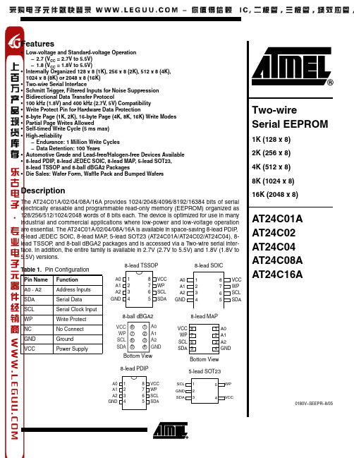
5 WP 4 VCC
Two-wire Serial EEPROM
1K (128 x 8) 2K (256 x 8) 4K (512 x 8) 8K (1024 x 8) 16K (2048 x 8)
AT24C01A AT24C02 AT24C04 AT24C08A AT24C16A
0180V–SEEPR–8/05
1
Absolute Maximum Ratings
Operating Temperature..................................–55°C to +125°C Storage Temperature .....................................–65°C to +150°C Voltage on Any Pin with Respect to Ground .................................... –1.0V to +7.0V Maximum Operating Voltage .......................................... 6.25V DC Output Current........................................................ 5.0 mA
5 SDA GND 4
8 VCC 7 WP 6 SCL 5 SDA
SCL WP NC GND VCC
Serial Clock Input Write Protect No Connect Ground Power Supply
8-ball dBGA2
VCC 8 WP 7 SCL 6 SDA 5
IC卡24C01资料
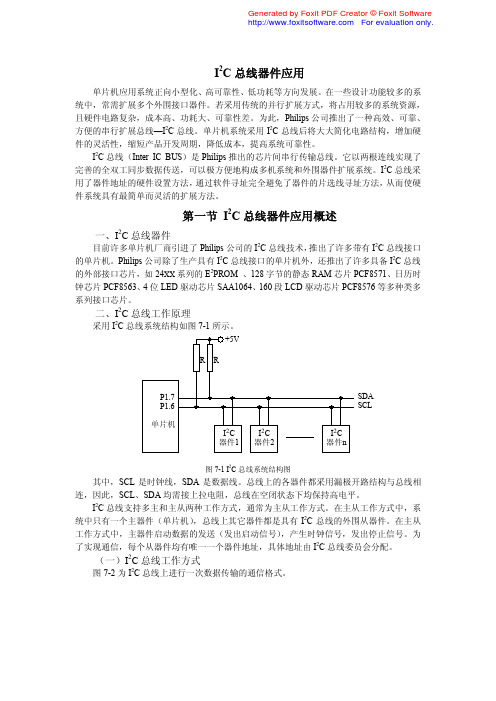
I2C总线器件应用单片机应用系统正向小型化、高可靠性、低功耗等方向发展。
在一些设计功能较多的系统中,常需扩展多个外围接口器件。
若采用传统的并行扩展方式,将占用较多的系统资源,且硬件电路复杂,成本高、功耗大、可靠性差。
为此,Philips公司推出了一种高效、可靠、方便的串行扩展总线—I2C总线。
单片机系统采用I2C总线后将大大简化电路结构,增加硬件的灵活性,缩短产品开发周期,降低成本,提高系统可靠性。
I2C总线(Inter IC BUS)是Philips推出的芯片间串行传输总线。
它以两根连线实现了完善的全双工同步数据传送,可以极方便地构成多机系统和外围器件扩展系统。
I2C总线采用了器件地址的硬件设置方法,通过软件寻址完全避免了器件的片选线寻址方法,从而使硬件系统具有最简单而灵活的扩展方法。
第一节I2C总线器件应用概述一、I2C总线器件目前许多单片机厂商引进了Philips公司的I2C总线技术,推出了许多带有I2C总线接口的单片机。
Philips公司除了生产具有I2C总线接口的单片机外,还推出了许多具备I2C总线的外部接口芯片,如24XX系列的E2PROM 、128字节的静态RAM芯片PCF8571、日历时钟芯片PCF8563、4位LED驱动芯片SAA1064、160段LCD驱动芯片PCF8576等多种类多系列接口芯片。
二、I2C总线工作原理采用I2C总线系统结构如图7-1所示。
图7-1 I2C总线系统结构图其中,SCL是时钟线,SDA是数据线。
总线上的各器件都采用漏极开路结构与总线相连,因此,SCL、SDA均需接上拉电阻,总线在空闭状态下均保持高电平。
I2C总线支持多主和主从两种工作方式,通常为主从工作方式。
在主从工作方式中,系统中只有一个主器件(单片机),总线上其它器件都是具有I2C总线的外围从器件。
在主从工作方式中,主器件启动数据的发送(发出启动信号),产生时钟信号,发出停止信号。
为了实现通信,每个从器件均有唯一一个器件地址,具体地址由I2C总线委员会分配。
华师大版数学七年级下册全册单元测试卷含答案
华师大版数学七年级下册全册单元测试卷含答案绝密★启用前初一数学一元一次方程单元测试评卷人得分一、选择题(每小题2分,共30分)1.下列方程中,是一元一次方程的是()(A)(B)(C)(D)2.在解方程-=1时,去分母正确的是A、3(x-1)-2(2+3x)=1B、3(x-1)-2(2x+3)=6C、3x-1-4x+3=1D、3x-1-4x+3=63.下列方程变形不正确的是()A、4x+8=0x+2=0B、x+5=3-3x4x=-2C、2x=15D、3x=-1x=-34.关于的方程的解是3,则的值是()A.4B.—4C.5D.—55.某工厂计划每天烧煤5吨,实际每天少烧2吨,吨煤多烧了20天,则可列的方程是()A.B.C.D.6.某个体户在一次买卖中同时卖出两件上衣,售价都是165元,若按成本价计算,其中一件盈利25%,另一件亏损25%,在这次买卖中他()A、赚22元B、赚36元C、亏22元D、不赚不亏.7.下列方程中,解是x=1的是()A.B.C.D.8.、若是一元一次方程,则m的值是()A.±1B.-1C.1D.29.某校一年级有64人,分成甲、乙、丙三队,其人数比为4:5:7。
若由外校转入1人加入乙队,则后来乙与丙的人数比为何?A.3:4B.4:5C.5:6D.6:710.下列方程中,一元一次方程的有()个。
①2x-3y=6②x2-5x+6=0③3(x-2)=1-2x④⑤3x-2(6-x)A.1B.2C.3D.411.方程2x+1=3与2-=0的解相同,则a的值是()A.7B.0C.3D.512.有m辆客车及n个人,若每辆乘40人,则还有10人不能上车,若每辆客车乘43人,则只有1人不能上车,有下列四个等式:①;②;③;④,其中正确的是().A.①②B.②④C.①③D.③④13.若与互为倒数,那么x的值等于()A.B.C.D.14.若代数式(a-1)x│a│+8=0是关于x的一元一次方程,则a的值为()A.-1B.0C.1D.1或-115.下面是一个被墨水污染过的方程:,答案显示此方程的解是x=-1,被墨水遮盖的是一个常数,则这个常数是A.1B.-1C.D.二、填空题(每小题3分,共30分)16.若方程2x-5=1和的解相同,则a=17..写出满足下列条件的一个一元一次方程:①未知数的系数是;②方程的解是3,这样的方程可以是:____________.18.若式子的值比式子的值少5,那么__________.19.若,,则的取值为_____________.20.小李在解方程(x为未知数)时,误将-x看作+x,解得方程的解,则原方程的解为___________________________。
第7章岩体本构关系与强度理论

整理得:
P cos P sin tg j C j
(7-99) (7-100)
当C j 0 时,上式变为:P cos 整理得: 即:
P sin tg j
900 j
板状 结构体
横向弯曲 悬臂弯曲
结 构 面
坚硬 结构面
闭合变形 错动变形 挤出变形 滑动变形
软弱 结构面
二、 岩体变形机制与本构关系
岩体变形=F(岩石、岩体结构、压力、温度、时间):
其中前两项为岩体的实体,后二者为岩体赋存环境,最
后一项表征变形过程。
其数学表达式称为本构方程:
u f ( E, , usb , , T , t )
第7章 岩体本构关系 与强度理论
岩、工系
刘佑荣
7.3 岩石强度理论与破坏判据
一、 库仑强度准则 二、 莫尔强度准则 三、 格里菲斯强度准则
四、 德鲁克一普拉格准则
四、德鲁克一普拉格准则
在 C-M 准则和在八面体强度理论中的Mises 准则基础上的扩展和推广而得的,表达式为:
f I1 J 2 K 0
1,0
(7-90)
( 1 3 ) 2 8 t 1 3 t 3
1 3 3 0 1 3 3 0
或
2 4 t ( t )
对岩体拉张破坏进行判别。
三、 剪破坏判据
岩体剪破坏可以用库伦-莫尔判据进行研究,其判据式在岩 石破坏判据中已有讨论。但应注意,对于岩体,在用库伦-莫尔 判据时,必须用岩体的应力与强度参数,才能进行正确的判据。
或
(7-84)
DDZX24C-7资料
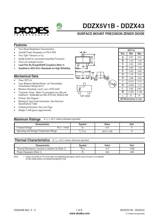
PbLead-free·Very Sharp Breakdown Characteristics ·300mW Power Dissipation on FR-4 PCB ·Very Tight Tolerance on V Z·Ideally Suited for Automated Assembly Processes ·Very Low Leakage Current·Lead Free By Design/RoHS Compliant (Note 7)·Qualified to AEC-Q101 Standards for High ReliabilityFeaturesMaximum Ratings@ T A = 25°C unless otherwise specifiedNote:1. Device mounted on FR-4 PCB with recommended pad layout, which can be found on our website at /datasheets/ap02001.pdf.Mechanical DataDDZX5V1B - DDZX43SURFACE MOUNT PRECISION ZENER DIODETOP VIEW·Case: SOT-23·Case Material: Molded Plastic. UL Flammability Classification Rating 94V-0·Moisture Sensitivity: Level 1 per J-STD-020C ·Terminals: Finish - Matte Tin annealed over Alloy 42leadframe. Solderable per MIL-STD-202, Method 208·Polarity: See Diagram·Marking & Type Code Information: See Electrical Specifications Table·Ordering Information: See Last Page ·Weight: 0.008 grams (approximate)Thermal Characteristics@ T A = 25°C unless otherwise specifiedElectrical Characteristics Table 1@ T A = 25°C unless otherwise specified Notes:2. The Zener voltage is measured 40ms after power is supplied.3. For inquiries on tighter tolerances, or alternate nominal zener voltages, please contact your Diodes Inc. sales representative for availability and minimum order details.4. f = 1kHz.5. Short duration pulse test used to minimize self-heating effect.0.20.40.60.81.21.0I ,I N S T A N T A N E O U S F O R W A R D C U R R E N T (m A )F V ,INSTANTANEOUS FORWARD VOLTAGE (V)Fig.2Typical Forward CharacteristicsF 100101.00.10.0110008.011.013.015.0I ,Z E N E R C U R R E N T (A )Z V ,ZENER BREAKDOWN VOLTAGE (V)Fig.5Typical Reverse Characteristics,DDZX10C -DDZX14Z 10.012.014.01m100n10m100m060120180240300255075100125150P ,P O W E R D I S S I P A T I O N (m W )d T ,AMBIENT TEMPERATURE (C)Fig.1Power Dissipation vs Ambient TemperatureA °3601m 100n10m100m4.06.08.010.0I ,Z E N E R C U R R E N T (A )Z 5.07.09.0V ,ZENER BREAKDOWN VOLTAGE (V)Fig.4Typical Reverse Characteristics,DDZX5V6B -DDZX9V1CZ 10n100n 1m5I ,Z E N E R C U R R E N T (A )Z V ,ZENER BREAKDOWN VOLTAGE (V)Fig.3Typical Reverse CharacteristicsZ 10m100m 10152025303540450.1101001100010,00012131415161718V ,ZENER VOLTAGE (V)Fig.11Typical Zener Impedance Characteristics,DDZX12C -DDZX18CZ 0.1101001100010,0005.06.07.08.09.010.011.012V ,ZENER VOLTAGE (V)Fig.10Typical Zener Impedance Characteristics,DDZX5V6B -DDZX12CZ 38424650I ,Z E N E R C U R R E N T (A )Z V ,ZENER BREAKDOWN VOLTAGE (V)Fig.9Typical Reverse Characteristics,DDZX43Z 4044481m100n10m100m26303438I ,Z E N E R C U R R E N T (A )Z V ,ZENER BREAKDOWN VOLTAGE (V)Fig.8Typical Reverse Characteristics,DDZX27D -DDZX36Z 2832361m100n10m100m14161820I ,Z E N E R C U R R E N T (A )Z V ,ZENER BREAKDOWN VOLTAGE (V)Fig.6Typical Reverse Characteristics,DDZX15-DDZX18CZ 1517191m100n10m100m 19212325I ,Z E N E R C U R R E N T (A )Z V ,ZENER BREAKDOWN VOLTAGE (V)Fig.7Typical Reverse Characteristics,DDZX20C -DDZX24CZ 2022241m100n10m100m-0.080.12-0.04-0.06202630T C o f V ,T E M P E R A T U R E C O E F F I C I E N T O F Z E N E R V O L T A G E (%/°C )Z V ,ZENER VOLTAGE (V)Z Fig.17Typical Temperature Coefficient of Zener Voltage,DDZX20C-DDZX30D242228-0.0200.020.040.060.080.10-0.080.12-0.04-0.06101620T C o f V ,T E M P E R A T U R E C O E F F I C I E N T O F Z E N E R V O L T A G E (%/°C )Z V ,ZENER VOLTAGE (V)Z Fig.16Typical Temperature Coefficient ofZener Voltage vs.Zener Voltage,DDZX10C-DDZX20C141218-0.0200.020.040.060.080.10-0.080.12-0.04-0.060610T C o f V ,T E M P E R A T U R E C O E F F I C I E N T O F Z E N E R V O L T A G E (%/°C )Z V ,ZENER VOLTAGE (V)Z Fig.15Typical Temperature Coefficient ofZener Voltage vs.Zener Voltage,DDZX6V2B-DDZX10C428-0.0200.020.040.060.080.100.1101001100010,00036384042444648V ,ZENER VOLTAGE (V)Fig.14Typical Zener Impedance Characteristics,DDZX36-DDZX43Z 0.1101001100010,00018192021222324V ,ZENER VOLTAGE (V)Fig.12Typical Zener Impedance Characteristics,DDZX18C -DDZX24CZ 0.1101001100010,000242628303234V ,ZENER VOLTAGE (V)Fig.13Typical Zener Impedance Characteristics,DDZX24C -DDZX33Z-0.080.12-0.04-0.06304250T C o f V ,T E M P E R A T U R E C O E F F I C I E N T O F Z E N E R V O L T A G E (%/°C )Z V ,ZENER VOLTAGE (V)Z Fig.18Typical Temperature Coefficient ofZener Voltage,DDZX30D-DDZX43383446-0.0200.020.040.060.080.10C ,T O T A L C A P A C I T A N C E (p F )T 110100V ,NOMINAL ZENER VOLTAGE (V)Fig.19Total Capacitance vs Nominal Zener VoltageZOrdering InformationDate Code KeyKXX = Product Type Marking Code (See Table 1)YM = Date Code Marking Y = Year (ex: T = 2006)M = Month (ex: 9 = September)(Note 6)KXXY M* Example: The part number for the 6.2 Volt device would be DDZX6V2B-7.Note : 6. For Packaging Details, go to our website at /datasheets/ap02007.pdf.7. No purposefully added lead.Marking InformationIMPORTANT NOTICELIFE SUPPORTDiodes Incorporated and its subsidiaries reserve the right to make modifications,enhancements,improvements,corrections or other changes without further notice to any product herein.Diodes Incorporated does not assume any liability arising out of the application or use of any product described herein;neither does it convey any license under its patent rights,nor the rights of others.The user of products in such applications shall assume all risks of such use and will agree to hold Diodes Incorporated and all the companies whose products are represented on our website,harmless against all damages.Diodes Incorporated products are not authorized for use as critical components in life support devices or systems without the expressed written approval of the President of Diodes Incorporated.。
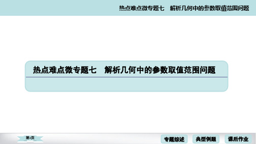
热点难点微专题七解析几何中的参数取值范围问题
第22页
专题综述 典型例题 课后作业
热点难点微专题七 解析几何中的参数取值范围问题
代入直线 PA 的方程得 y1=104-y03x0. 则 k1=x0y-0 2,
4y0 k2=x1y-1 1=11001x-00--3x1302x-0 1=13x40y-0 22.
第23页
专题综述 典型例题 课后作业
当且仅当 k=± 22时等号成立,此时|S1-S2|的最大值为 4. 综上,|S1-S2|的最大值为 4.
第13页
专题综述 典型例题 课后作业
热点难点微专题七 解析几何中的参数取值范围问题
7. 如图,在平面直角坐标系 xOy 中,椭圆ax22+by22=1(a>b>0)的离心率为12,过椭圆 右焦点 F 作两条互相垂直的弦 AB 与 CD.当直线 AB 斜率为 0 时,AB+CD=7. (1) 求椭圆的方程; (2) 求 AB+CD 的取值范围.
热点难点微专题七 解析几何中的参数取值范围问题
9. 在平面直角坐标系 xOy 中,有一动点 P 到直线 x=433的距离与到点( 3,0)的
距离比值是2
3 3.
(1) 求动点 P 的轨迹 C 的方程;
(2) 已知点 A(2,0),若 P 不在 x 轴上,过点 O 作线段 AP 的垂线 l 交曲线 C 于点 D,
第2页
专题综述 典型例题 课后作业
热点难点微专题七 解析几何中的参数取值范围问题
2. 已知 F1,F2 是椭圆的两个焦点,满足M→F1·M→F2=0 的点 M 总在椭圆内部,则椭
圆离心率的取值范围是________________.
0,
2 2
解析:满足M→F1·M→F2=0 的点 M 在圆 x2+y2=c2 上,由题意知方程组
7.4.2超几何分布课件2023-2024学年高二下学期数学人教A版(2019)选择性必修第三册

假设每名候选人都有相同的机会被选到,若X表示选到高二(1)班的候选人的
人数,则E(X)等于( D )
3
8
3
4
A.4
B.9
C.8
D.5
解析 法一(公式法) 由题意得随机变量X服从超几何分布n=2,M=4,N=10,
则 E(X)=nNM=2×140=54. 法二 由题意知,X的可能取值为0,1,2, P(X=0)=CC12260=1455=31,
提示 P(X=1 或 X=2)=P(X=1)+P(X=2)=56.
2.填空 (1)一般地,假设一批产品共有N件,其中有M件次品.从N件产品中随
机抽取n件(不放回),用X表示抽取的n件产品中的次品数,则X的分布列为P(X
CkMCnN--kM
=k)=_____C_Nn______,k=m,m+1,m+2,…,r.其中n,N,M∈N*,M≤N,
温馨提醒 (1)在超几何分布的模型中,“任取n件”应理解为“不放回地一次 取一件,连续取n件”. (2)超几何分布的特点:①不放回抽样;②考察对象分两类;③实质是古典概 型.
3.做一做 (1)一批产品共10件,次品率为20%,从中任取2件,则恰好取到1件
次品的概率为( B )
A.2485
B.1465
7.袋中装有5个红球和4个黑球,从袋中任取4个球,取到1个红球得3分,取到1 5
C.4115
D.1475
解析 设取到的次品数为X,则X服从超几何分布. 因此 P(X=1)=CC12C21081=1465.
(2)从装有大小、质地相同的3个红球、2个白球的袋中随机取2个球,设其中有ξ 6
个红球,则E(ξ)=____5____.
解析 E(ξ)=2×35=65.
24C08WP M24C08-WMN6TP

1/29March 2004M24C16, M24C08M24C04, M24C02, M24C0116Kbit, 8Kbit, 4Kbit, 2Kbit and 1Kbit Serial I²C Bus EEPROMFEATURES SUMMARY■Two Wire I 2C Serial Interface Supports 400kHz Protocol ■Single Supply Voltage:– 4.5 to 5.5V for M24Cxx – 2.5 to 5.5V for M24Cxx-W – 1.8 to 5.5V for M24Cxx-R ■Write Control Input■BYTE and PAGE WRITE (up to 16 Bytes)■RANDOM and SEQUENTIAL READ Modes ■Self-Timed Programming Cycle ■Automatic Address Incrementing ■Enhanced ESD/Latch-Up Behavior ■More than 1 Million Erase/Write Cycles ■More than 40 Year Data RetentionM24C16, M24C08, M24C04, M24C02, M24C01TABLE OF CONTENTSFEATURES SUMMARY . . . . . . . . . . . . . . . . . . . . . . . . . . . . . . . . . . . . . . . . . . . . . . . . . . . . . . . . . . . . .1 Figure 1.Packages. . . . . . . . . . . . . . . . . . . . . . . . . . . . . . . . . . . . . . . . . . . . . . . . . . . . . . . . . . . . . .1SUMMARY DESCRIPTION. . . . . . . . . . . . . . . . . . . . . . . . . . . . . . . . . . . . . . . . . . . . . . . . . . . . . . . . . . .4Figure 2.Logic Diagram . . . . . . . . . . . . . . . . . . . . . . . . . . . . . . . . . . . . . . . . . . . . . . . . . . . . . . . . . .4 Table 1.Signal Names . . . . . . . . . . . . . . . . . . . . . . . . . . . . . . . . . . . . . . . . . . . . . . . . . . . . . . . . . .4 Power On Reset: VCC Lock-Out Write Protect. . . . . . . . . . . . . . . . . . . . . . . . . . . . . . . . . . . . . . .4 Figure 3.DIP, SO, TSSOP and MLP Connections (Top View). . . . . . . . . . . . . . . . . . . . . . . . . . . . .4SIGNAL DESCRIPTION . . . . . . . . . . . . . . . . . . . . . . . . . . . . . . . . . . . . . . . . . . . . . . . . . . . . . . . . . . . . .5Serial Clock (SCL). . . . . . . . . . . . . . . . . . . . . . . . . . . . . . . . . . . . . . . . . . . . . . . . . . . . . . . . . . . . . . .5 Serial Data (SDA) . . . . . . . . . . . . . . . . . . . . . . . . . . . . . . . . . . . . . . . . . . . . . . . . . . . . . . . . . . . . . . .5 Chip Enable (E0, E1, E2) . . . . . . . . . . . . . . . . . . . . . . . . . . . . . . . . . . . . . . . . . . . . . . . . . . . . . . . . .5 Write Control (WC) . . . . . . . . . . . . . . . . . . . . . . . . . . . . . . . . . . . . . . . . . . . . . . . . . . . . . . . . . . . . . .5 Figure 4.Maximum RL Value versus Bus Capacitance (CBUS) for an I2C Bus . . . . . . . . . . . . . . .5 Figure 5.I2C Bus Protocol . . . . . . . . . . . . . . . . . . . . . . . . . . . . . . . . . . . . . . . . . . . . . . . . . . . . . . . .6 Table 2.Device Select Code. . . . . . . . . . . . . . . . . . . . . . . . . . . . . . . . . . . . . . . . . . . . . . . . . . . . . .6DEVICE OPERATION. . . . . . . . . . . . . . . . . . . . . . . . . . . . . . . . . . . . . . . . . . . . . . . . . . . . . . . . . . . . . . .7Start Condition. . . . . . . . . . . . . . . . . . . . . . . . . . . . . . . . . . . . . . . . . . . . . . . . . . . . . . . . . . . . . . . . .7 Stop Condition. . . . . . . . . . . . . . . . . . . . . . . . . . . . . . . . . . . . . . . . . . . . . . . . . . . . . . . . . . . . . . . . .7 Acknowledge Bit (ACK) . . . . . . . . . . . . . . . . . . . . . . . . . . . . . . . . . . . . . . . . . . . . . . . . . . . . . . . . .7 Data Input. . . . . . . . . . . . . . . . . . . . . . . . . . . . . . . . . . . . . . . . . . . . . . . . . . . . . . . . . . . . . . . . . . . . .7 Memory Addressing . . . . . . . . . . . . . . . . . . . . . . . . . . . . . . . . . . . . . . . . . . . . . . . . . . . . . . . . . . . .7 Table 3.Operating Modes. . . . . . . . . . . . . . . . . . . . . . . . . . . . . . . . . . . . . . . . . . . . . . . . . . . . . . . .7 Figure 6.Write Mode Sequences with WC=1 (data write inhibited). . . . . . . . . . . . . . . . . . . . . . . . .8 Write Operations . . . . . . . . . . . . . . . . . . . . . . . . . . . . . . . . . . . . . . . . . . . . . . . . . . . . . . . . . . . . . . .8 Byte Write. . . . . . . . . . . . . . . . . . . . . . . . . . . . . . . . . . . . . . . . . . . . . . . . . . . . . . . . . . . . . . . . . . . . .8 Page Write . . . . . . . . . . . . . . . . . . . . . . . . . . . . . . . . . . . . . . . . . . . . . . . . . . . . . . . . . . . . . . . . . . . .8 Figure 7.Write Mode Sequences with WC=0 (data write enabled) . . . . . . . . . . . . . . . . . . . . . . . . .9 Figure 8.Write Cycle Polling Flowchart using ACK . . . . . . . . . . . . . . . . . . . . . . . . . . . . . . . . . . . .10 Minimizing System Delays by Polling On ACK. . . . . . . . . . . . . . . . . . . . . . . . . . . . . . . . . . . . . .10 Figure 9.Read Mode Sequences. . . . . . . . . . . . . . . . . . . . . . . . . . . . . . . . . . . . . . . . . . . . . . . . . .11 Read Operations . . . . . . . . . . . . . . . . . . . . . . . . . . . . . . . . . . . . . . . . . . . . . . . . . . . . . . . . . . . . . .11 Random Address Read. . . . . . . . . . . . . . . . . . . . . . . . . . . . . . . . . . . . . . . . . . . . . . . . . . . . . . . . .11 Current Address Read . . . . . . . . . . . . . . . . . . . . . . . . . . . . . . . . . . . . . . . . . . . . . . . . . . . . . . . . .11 Sequential Read. . . . . . . . . . . . . . . . . . . . . . . . . . . . . . . . . . . . . . . . . . . . . . . . . . . . . . . . . . . . . . .12 Acknowledge in Read Mode. . . . . . . . . . . . . . . . . . . . . . . . . . . . . . . . . . . . . . . . . . . . . . . . . . . . .12INITIAL DELIVERY STATE. . . . . . . . . . . . . . . . . . . . . . . . . . . . . . . . . . . . . . . . . . . . . . . . . . . . . . . . . .12MAXIMUM RATING. . . . . . . . . . . . . . . . . . . . . . . . . . . . . . . . . . . . . . . . . . . . . . . . . . . . . . . . . . . . . . . .13 Table 4.Absolute Maximum Ratings. . . . . . . . . . . . . . . . . . . . . . . . . . . . . . . . . . . . . . . . . . . . . . .132/29M24C16, M24C08, M24C04, M24C02, M24C01DC and AC PARAMETERS . . . . . . . . . . . . . . . . . . . . . . . . . . . . . . . . . . . . . . . . . . . . . . . . . . . . . . . . .14Table 5.Operating Conditions (M24Cxx) . . . . . . . . . . . . . . . . . . . . . . . . . . . . . . . . . . . . . . . . . . .14 Table 6.Operating Conditions (M24Cxx-W) . . . . . . . . . . . . . . . . . . . . . . . . . . . . . . . . . . . . . . . . .14 Table 7.Operating Conditions (M24Cxx-R). . . . . . . . . . . . . . . . . . . . . . . . . . . . . . . . . . . . . . . . . .14 Table 8.AC Measurement Conditions. . . . . . . . . . . . . . . . . . . . . . . . . . . . . . . . . . . . . . . . . . . . . .15 Figure 10.AC Measurement I/O Waveform. . . . . . . . . . . . . . . . . . . . . . . . . . . . . . . . . . . . . . . . . . .15 Table 9.Input Parameters. . . . . . . . . . . . . . . . . . . . . . . . . . . . . . . . . . . . . . . . . . . . . . . . . . . . . . .15 Table 10.DC Characteristics (M24Cxx, Device Grade 6). . . . . . . . . . . . . . . . . . . . . . . . . . . . . . . .15 Table 11.DC Characteristics (M24Cxx, Device Grade 3). . . . . . . . . . . . . . . . . . . . . . . . . . . . . . . .16 Table 12.DC Characteristics (M24Cxx-W, Device Grade 6). . . . . . . . . . . . . . . . . . . . . . . . . . . . . .16 Table 13.DC Characteristics (M24Cxx-W, Device Grade 3). . . . . . . . . . . . . . . . . . . . . . . . . . . . . .17 Table 14.DC Characteristics (M24Cxx-R) . . . . . . . . . . . . . . . . . . . . . . . . . . . . . . . . . . . . . . . . . . .17 Table 15.AC Characteristics (M24Cxx, Device Grade 6). . . . . . . . . . . . . . . . . . . . . . . . . . . . . . . .18 Table 16.AC Characteristics (M24Cxx, Device Grade 3; M24Cxx-W, Device Grade 6 or 3). . . . .18 Table 17.AC Characteristics (M24Cxx-R). . . . . . . . . . . . . . . . . . . . . . . . . . . . . . . . . . . . . . . . . . . .19 Figure 11.AC Waveforms . . . . . . . . . . . . . . . . . . . . . . . . . . . . . . . . . . . . . . . . . . . . . . . . . . . . . . . .20PACKAGE MECHANICAL . . . . . . . . . . . . . . . . . . . . . . . . . . . . . . . . . . . . . . . . . . . . . . . . . . . . . . . . . .21Figure 12.PDIP8 – 8 pin Plastic DIP, 0.25mm lead frame, Package Outline . . . . . . . . . . . . . . . . .21 Table 18.PDIP8 – 8 pin Plastic DIP, 0.25mm lead frame, Package Mechanical Data. . . . . . . . . .21 Figure 13.SO8 narrow – 8 lead Plastic Small Outline, 150 mils body width, Package Outline . . . .22 Table 19.SO8 narrow – 8 lead Plastic Small Outline, 150 mils body width, Package Mechanical Data 22Figure 14.UFDFPN8 (MLP8) 8-lead Ultra thin Fine pitch Dual Flat Package No lead 2x3mm², Outline 23Table 20.UFDFPN8 (MLP8) 8-lead Ultra thin Fine pitch Dual Flat Package No lead 2x3mm², Data.23Figure 15.TSSOP8 – 8 lead Thin Shrink Small Outline, Package Outline . . . . . . . . . . . . . . . . . . .24 Table 21.TSSOP8 – 8 lead Thin Shrink Small Outline, Package Mechanical Data. . . . . . . . . . . .24 Figure 16.TSSOP8 3x3mm² – 8 lead Thin Shrink Small Outline, 3x3mm² body size, Package Outline 25Table 22.TSSOP8 3x3mm² – 8 lead Thin Shrink Small Outline, 3x3mm² body size, Mechanical Data 25PART NUMBERING . . . . . . . . . . . . . . . . . . . . . . . . . . . . . . . . . . . . . . . . . . . . . . . . . . . . . . . . . . . . . . .26Table 23.Ordering Information Scheme . . . . . . . . . . . . . . . . . . . . . . . . . . . . . . . . . . . . . . . . . . . . .26 Table 24.How to Identify Current and New Products by the Process Identification Letter. . . . . . .27REVISION HISTORY. . . . . . . . . . . . . . . . . . . . . . . . . . . . . . . . . . . . . . . . . . . . . . . . . . . . . . . . . . . . . . .28 Table 25.Document Revision History. . . . . . . . . . . . . . . . . . . . . . . . . . . . . . . . . . . . . . . . . . . . . . .283/29M24C16, M24C08, M24C04, M24C02, M24C014/29SUMMARY DESCRIPTIONThese I 2C-compatible electrically erasable pro-grammable memory (EEPROM) devices are orga-nized as 2048/1024/512/256/128x 8 (M24C16,M24C08, M24C04, M24C02, M24C01).I C uses a two wire serial interface, comprising a bi-directional data line and a clock line. The devic-es carry a built-in 4-bit Device Type Identifier code (1010) in accordance with the I 2C bus definition.The device behaves as a slave in the I 2C protocol,with all memory operations synchronized by the serial clock. Read and Write operations are initiat-ed by a Start condition, generated by the bus mas-ter. The Start condition is followed by a Device Table 2.),terminated by an acknowledge bit.When writing data to the memory, the device in-serts an acknowledge bit during the 9th bit time,following the bus master’s 8-bit transmission.When data is read by the bus master, the bus master acknowledges the receipt of the data byte in the same way. Data transfers are terminated by a Stop condition after an Ack for Write, and after a NoAck for Read.Table 1. Signal NamesPower On Reset: V CC Lock-Out Write Protect In order to prevent data corruption and inadvertent Write operations during Power-up, a Power On Reset (POR) circuit is included. At Power-up, the internal reset is held active until V CC has reached the POR threshold value, and all operations are disabled – the device will not respond to any com-mand. In the same way, when V CC drops from the operating voltage, below the POR threshold value,all operations are disabled and the device will not respond to any command.A stable and valid V CC (as defined in Table 6. and Table 7.) must be applied before applying any log-ic signal.Note: 1.NC = Not Connected2.See PACKAGE MECHANICAL section for package dimensions, and how to identify pin-1.E0, E1, E2Chip Enable SDA Serial Data SCL Serial Clock WC Write Control V CC Supply Voltage V SSGroundM24C16, M24C08, M24C04, M24C02, M24C01 SIGNAL DESCRIPTIONSerial Clock (SCL).This input signal is used to strobe all data in and out of the device. In applica-tions where this signal is used by slave devices to synchronize the bus to a slower clock, the bus master must have an open drain output, and a pull-up resistor can be connected from Serial Clock (SCL) to V CC. (Figure 4. indicates how the value of the pull-up resistor can be calculated). In most applications, though, this method of synchro-nization is not employed, and so the pull-up resis-tor is not necessary, provided that the bus master has a push-pull (rather than open drain) output. Serial Data (SDA).This bi-directional signal is used to transfer data in or out of the device. It is an open drain output that may be wire-OR’ed with other open drain or open collector signals on the bus. A pull up resistor must be connected from Se-rial Data (SDA) to V CC. (Figure 4. indicates how the value of the pull-up resistor can be calculated). Chip Enable (E0, E1, E2).These input signals are used to set the value that is to be looked for on the three least significant bits (b3, b2, b1) of the 7-bit Device Select Code. These inputs must be tied to V CC or V SS, to establish the Device Select Code.Write Control (WC).This input signal is useful for protecting the entire contents of the memory from inadvertent write operations. Write opera-tions are disabled to the entire memory array when Write Control (WC) is driven High. When uncon-nected, the signal is internally read as V IL, and Write operations are allowed.When Write Control (WC) is driven High, Device Select and Address bytes are acknowledged, Data bytes are not acknowledged.25/29M24C16, M24C08, M24C04, M24C02, M24C012Table 2. Device Select CodeDevice Type Identifier1Chip Enable2,3RW b7b6b5b4b3b2b1b0 M24C01Select Code1010E2E1E0RW M24C02Select Code1010E2E1E0RW M24C04Select Code1010E2E1A8RW M24C08Select Code1010E2A9A8RW M24C16Select Code1010A10A9A8RW Note: 1.The most significant bit, b7, is sent first.2.E0, E1 and E2 are compared against the respective external pins on the memory device.3.A10, A9 and A8 represent most significant bits of the address.6/297/29M24C16, M24C08, M24C04, M24C02, M24C01DEVICE OPERATIONThe device supports the I 2C protocol. This is sum-marized in Figure 5.. Any device that sends data on to the bus is defined to be a transmitter, and any device that reads the data to be a receiver.The device that controls the data transfer is known as the bus master, and the other as the slave de-vice. A data transfer can only be initiated by the bus master, which will also provide the serial clock for synchronization. The M24Cxx device is always a slave in all communication.Start ConditionStart is identified by a falling edge of Serial Data (SDA) while Serial Clock (SCL) is stable in the High state. A Start condition must precede any data transfer command. The device continuously monitors (except during a Write cycle) Serial Data (SDA) and Serial Clock (SCL) for a Start condition,and will not respond unless one is given.Stop ConditionStop is identified by a rising edge of Serial Data (SDA) while Serial Clock (SCL) is stable and driv-en High. A Stop condition terminates communica-tion between the device and the bus master. A Read command that is followed by NoAck can be followed by a Stop condition to force the device into the Stand-by mode. A Stop condition at the end of a Write command triggers the internal EE-PROM Write cycle.Acknowledge Bit (ACK)The acknowledge bit is used to indicate a success-ful byte transfer. The bus transmitter, whether it be bus master or slave device, releases Serial Data (SDA) after sending eight bits of data. During the 9th clock pulse period, the receiver pulls Serial Data (SDA) Low to acknowledge the receipt of the eight data bits.Data InputDuring data input, the device samples Serial Data (SDA) on the rising edge of Serial Clock (SCL).For correct device operation, Serial Data (SDA)must be stable during the rising edge of Serial Clock (SCL), and the Serial Data (SDA) signal must change only when Serial Clock (SCL) is driv-en Low.Memory AddressingTo start communication between the bus master and the slave device, the bus master must initiate a Start condition. Following this, the bus master sends the Device Select Code, shown in Table 2.(on Serial Data (SDA), most significant bit first).The Device Select Code consists of a 4-bit Device Type Identifier, and a 3-bit Chip Enable “Address”(E2, E1, E0). To address the memory array, the 4-bit Device Type Identifier is 1010b.Each device is given a unique 3-bit code on the Chip Enable (E0, E1, E2) inputs. When the Device Select Code is received, the device only responds if the Chip Enable Address is the same as the val-ue on the Chip Enable (E0, E1, E2) inputs. How-ever, those devices with larger memory capacities (the M24C16, M24C08 and M24C04) need more address bits. E0 is not available for use on devices that need to use address line A8; E1 is not avail-able for devices that need to use address line A9,and E2 is not available for devices that need to use address line A10 (see Figure 3. and Table 2. for details). Using the E0, E1 and E2 inputs, up to eight M24C02 (or M24C01), four M24C04, two M24C08 or one M24C16 devices can be connect-ed to one I 2C bus. In each case, and in the hybrid cases, this gives a total memory capacity of 16Kbits, 2KBytes (except where M24C01 devic-es are used).The 8th set to 1 for Read and 0 for Write operations.If a match occurs on the Device Select code, the corresponding device gives an acknowledgment on Serial Data (SDA) during the 9th bit time. If the device does not match the Device Select code, it deselects itself from the bus, and goes into Stand-by mode.Table 3. Operating ModesNote: 1.X = V IH or V IL .ModeRW bit WC 1Bytes Initial SequenceCurrent Address Read 1X 1START, Device Select, RW = 1Random Address Read 0X 1START, Device Select, RW = 0, Address 1X reSTART, Device Select, RW = 1Sequential Read 1X ≥ 1Similar to Current or Random Address Read Byte Write 0V IL 1START, Device Select, RW = 0Page WriteV IL≤ 16START, Device Select, RW = 0M24C16, M24C08, M24C04, M24C02, M24C018/29Following a Start condition the bus master sends a Device Select Code with the RW bit reset to 0.The device acknowledges this, as shown in Figure 7., and waits for an address byte. The device re-sponds to the address byte with an acknowledge bit, and then waits for the data byte.When the bus master generates a Stop condition immediately after the Ack bit (in the “10th bit” time slot), either at the end of a Byte Write or a Page Write, the internal memory Write cycle is triggered.A Stop condition at any other time slot does not trigger the internal Write cycle.During the internal Write cycle, Serial Data (SDA)and Serial Clock (SCL) are ignored, and the de-vice does not respond to any requests.Byte WriteAfter the Device Select code and the address byte,the bus master sends one data byte. If the ad-dressed location is Write-protected, by Write Con-trol (WC) being driven High (during the period frombyte), the device replies to the data byte with NoAck, as shown in Figure 6., and the location is not modified. If, instead, the addressed location is not Write-protected, the device replies with Ack.The bus master terminates the transfer by gener-ating a Stop condition, as shown in Figure 7..Page WriteThe Page Write mode allows up to 16 bytes to be written in a single Write cycle, provided that they are all located in the same page in the memory:that is, the most significant memory address bits are the same. If more bytes are sent than will fit up to the end of the page, a condition known as ‘roll-over’ occurs. This should be avoided, as data starts to become overwritten in an implementation dependent way.The bus master sends from 1 to 16 bytes of data,each of which is acknowledged by the device if Write Control (WC) is Low. If the addressed loca-ing driven High (during the period from the StartM24C16, M24C08, M24C04, M24C02, M24C01condition until the end of the address byte), the de-vice replies to the data bytes with NoAck, as shown in Figure 6., and the locations are not mod-ified. After each byte is transferred, the internal byte address counter (the 4 least significant ad-dress bits only) is incremented. The transfer is ter-minated by the bus master generating a Stop condition.9/29M24C16, M24C08, M24C04, M24C02, M24C0110/29During the internal Write cycle, the device discon-nects itself from the bus, and writes a copy of the data from its internal latches to the memory cells.The maximum Write time (t w ) is shown in Table 15. to Table 17., but the typical time is shorter. To make use of this, a polling sequence can be used by the bus master.The sequence, as shown in Figure 8., is:–Step 1: the bus master issues a Start condition followed by a Device Select Code (the first byte of the new instruction).–Step 2: if the device is busy with the internal Write cycle, no Ack will be returned and the bus master goes back to Step 1. If the device has terminated the internal Write cycle, it responds with an Ack, indicating that the device is ready to receive the second part of the instruction (the first byte of this instruction having been sent during Step 1).Read OperationsRead operations are performed independently of the state of the Write Control (WC) signal.The device has an internal address counter which is incremented each time a byte is read. Random Address ReadA dummy Write is first performed to load the ad-dress into this address counter (as shown in Fig-ure 9.) but without sending a Stop condition. Then, the bus master sends another Start condition, and repeats the Device Select Code, with the RW bit set to 1. The device acknowledges this, and out-puts the contents of the addressed byte. The bus master must not acknowledge the byte, and termi-nates the transfer with a Stop condition.Current Address ReadFor the Current Address Read operation, following a Start condition, the bus master only sends a De-vice Select Code with the RW bit set to 1. The de-vice acknowledges this, and outputs the byte addressed by the internal address counter. The counter is then incremented. The bus master ter-minates the transfer with a Stop condition, as shown in Figure 9., without acknowledging the byte.11/29Sequential ReadThis operation can be used after a Current Ad-dress Read or a Random Address Read. The bus master does acknowledge the data byte output, and sends additional clock pulses so that the de-vice continues to output the next byte in sequence. To terminate the stream of bytes, the bus master must not acknowledge the last byte, and must generate a Stop condition, as shown in Figure 9.. The output data comes from consecutive address-es, with the internal address counter automatically incremented after each byte output. After the last memory address, the address counter ‘rolls-over’, and the device continues to output data from memory address 00h.Acknowledge in Read ModeFor all Read commands, the device waits, after each byte read, for an acknowledgment during the 9th bit time. If the bus master does not drive Serial Data (SDA) Low during this time, the device termi-nates the data transfer and switches to its Stand-by mode.INITIAL DELIVERY STATEThe device is delivered with the memory array erased: all bits are set to 1 (each byte contains FFh).12/2913/29MAXIMUM RATINGStressing the device above the rating listed in the Absolute Maximum Ratings" table may cause per-manent damage to the device. These are stress ratings only and operation of the device at these or any other conditions above those indicated in the Operating sections of this specification is not im-plied. Exposure to Absolute Maximum Rating con-ditions for extended periods may affect device reliability. Refer also to the STMicroelectronics SURE Program and other relevant quality docu-ments.Table 4. Absolute Maximum RatingsNote: pliant with JEDEC Std J-STD-020B (for small body, Sn-Pb or Pb assembly), the ST ECOPACK ® 7191395 specification, andthe European directive on Restrictions on Hazardous Substances (RoHS) 2002/95/EU 2.JEDEC Std JESD22-A114A (C1=100pF, R1=1500 Ω, R2=500 Ω)Symbol ParameterMin.Max.Unit T STG Storage Temperature–65150°C T LEAD Lead Temperature during Soldering See note 1°C V IO Input or Output range –0.50 6.5V V CC Supply Voltage–0.50 6.5V V ESDElectrostatic Discharge Voltage (Human Body model) 2–40004000V14/29DC AND AC PARAMETERSThis section summarizes the operating and mea-surement conditions, and the DC and AC charac-teristics of the device. The parameters in the DC and AC Characteristic tables that follow are de-rived from tests performed under the Measure-ment Conditions summarized in the relevant tables. Designers should check that the operating conditions in their circuit match the measurement conditions when relying on the quoted parame-ters.Table 5. Operating Conditions (M24Cxx)Note: 1.This range is Not for New Design, and will soon be replaced by the M24Cxx-W range.Table 6. Operating Conditions (M24Cxx-W)Table 7. Operating Conditions (M24Cxx-R)Symbol ParameterMin.Max.Unit V CC Supply Voltage4.55.5V T AAmbient Operating Temperature (Device Grade 6)–4085°C Ambient Operating Temperature (Device Grade 3)–40125°CSymbol ParameterMin.Max.Unit V CC Supply Voltage2.5 5.5V T AAmbient Operating Temperature (Device Grade 6)–4085°C Ambient Operating Temperature (Device Grade 3)–40125°CSymbol ParameterMin.Max.Unit V CC Supply Voltage1.8 5.5V T AAmbient Operating Temperature–4085°C15/29Table 8. AC Measurement ConditionsTable 9. Input ParametersNote: 1.T A = 25°C, f = 400kHz2.Sampled only, not 100% tested.Table 10. DC Characteristics (M24Cxx, Device Grade 6)Note: 1.This range is Not for New Design, and will soon be replaced by the M24Cxx-Wxx6 range.Symbol ParameterMin.Max.Unit C LLoad Capacitance 100pF Input Rise and Fall Times 50ns Input Levels0.2V CC to 0.8V CC V Input and Output Timing Reference Levels0.3V CC to 0.7V CCVSymbol Parameter 1,2Test ConditionMin .Max .Unit C IN Input Capacitance (SDA)8pF C IN Input Capacitance (other pins)6pF Z WCL WC Input Impedance V IN < 0.5V 570k ΩZ WCH WC Input Impedance V IN > 0.7V CC 500k Ωt NSPulse width ignored(Input Filter on SCL and SDA)Single glitch100nsSymbol ParameterTest Condition(in addition to those in Table 5.)Min.Max.Unit I LI Input Leakage Current (SCL, SDA)V IN = V SS or V CC± 2µA I LO Output Leakage Current V OUT = V SS or V CC, SDA in Hi-Z ± 2µA I CC Supply CurrentV CC =5V , f c =400kHz (rise/fall time < 30ns)2mA I CC1Stand-by Supply Current V IN = V SS or V CC , V CC = 5V1µA V ILInput Low Voltage(E2, E1, E0, SCL, SDA)–0.450.3V CC V Input Low Voltage (WC)–0.450.5V V IH Input High Voltage(E2, E1, E0, SCL, SDA, WC)0.7V CC V CC +1V V OLOutput Low VoltageI OL = 3mA, V CC = 5V 0.4V16/29Table 11. DC Characteristics (M24Cxx, Device Grade 3)Note: 1.This range is Not for New Design, and will soon be replaced by the M24Cxx-Wxx3 range.Table 12. DC Characteristics (M24Cxx-W, Device Grade 6)Symbol ParameterTest Condition(in addition to those in Table 5.)Min.Max.Unit I LI Input Leakage Current (SCL, SDA)V IN = V SS or V CC± 2µA I LO Output Leakage Current V OUT = V SS or V CC, SDA in Hi-Z ± 2µA I CC Supply CurrentV CC =5V , f c =400kHz (rise/fall time < 30ns)3mA I CC1Stand-by Supply Current V IN = V SS or V CC , V CC = 5V5µA V ILInput Low Voltage(E2, E1, E0, SCL, SDA)–0.450.3V CC V Input Low Voltage (WC)–0.450.5V V IH Input High Voltage(E2, E1, E0, SCL, SDA, WC)0.7V CC V CC +1V V OLOutput Low VoltageI OL = 3mA, V CC = 5V 0.4VSymbol ParameterTest Condition(in addition to those in Table 6.)Min.Max.Unit I LI Input Leakage Current (SCL, SDA)V IN = V SS or V CC± 2µA I LO Output Leakage Current V OUT = V SS or V CC, SDA in Hi-Z ± 2µA I CC Supply CurrentV CC =2.5V, f c =400kHz (rise/fall time < 30ns)1mA I CC1Stand-by Supply Current V IN = V SS or V CC , V CC = 2.5V0.5µA V ILInput Low Voltage(E2, E1, E0, SCL, SDA)–0.450.3V CC V Input Low Voltage (WC)–0.450.5V V IH Input High Voltage(E2, E1, E0, SCL, SDA, WC)0.7V CC V CC +1V V OLOutput Low VoltageI OL = 2.1mA, V CC = 2.5V 0.4V。
青岛海信电器 LED55T28GPN(1100) 液晶电视 服务手册

R液晶电视服务手册 LED55T28GPN(1100)MST6i78机芯方案青岛海信电器股份有限公司开发中心开发一部2010.08LED55T28GPN(1100) (3)一、产品介绍 (3)(一)、产品外观介绍 (3)(二)、产品功能规格、特点介绍 (5)(三)、产品差异介绍: (6)二、方案概述: (6)三、原理说明 (6)电路框图构架: (6)电源分配 (7)四、产品爆炸图及明细 (26)五、主板及电源板图 (28)六、软件升级方法 (31)液晶电视服务手册LED55T28GPN(1100)一、产品介绍(一)、产品外观介绍LED55T28GPN(1100)外观:技术参数:各端子电平特性:(三)、产品差异介绍:本机型电路方面除采用模拟高频头外,其它与LED55T29GP相似。
结构方面采用全新结构。
二、方案概述:本机所采用MST6i78系列方案是我公司于2010年初开始主推的中高端多媒体+网络+数字电视单芯片机芯方案,其集成度非常高。
主要特点包括:1. 芯片内置了VIF及SIF解码,可以实现PAL、NTSC和SECAM 的接收;2. 同时芯片内置了4路HIMI输入(支持CEC功能,暂不开发)、3路YPbPr/RGB输入、5路AV输入、2路USB输入。
可以采用USB进行升级;3. 支持MPEG-2、H.264、AVS(up to 1920*1088@30fps)、VC1等多种解码;4.多媒体(USB2.0)功能,图片支持JPEG(8192x8192)、BMP(3000x3000)、PNG(3000x3000);音乐支持MP3、WMA、WAV;电影支持AVI、MP4、MPG、MPEG、VOB、TS、MOV、MKV、RM、RMVB、ASF、WMV、FLV;5.强大的Widget网络功能;6.支持wifi(USB dangle形式)功能。
三、原理说明电路框图构架:6i78 采用了3核独立CPU架构、提升性能:1、MIPS cpu:用于网络部分处理;2、32Bit CPU:用于TV的软件3、DSP:多媒体解码电源分配1. 电源部分---系统3.3Vstb 3.3Vstb 为待机3.3V,通过待机5V 转换而来,待机不受控。
人教版七年级数学上册课课练 1.3.2有理数的减法
人教版七年级数学上册课课练 1.3.2有理数的减法一、单选题1.计算1−|−3|=()A. -2B. 2C. 4D. -42.某地区2021年元旦的最高气温为9℃,最低气温为−2℃,那么该地区这天的最低气温比最高气温低()A. 7℃B. −7℃C. 11℃D. −11℃3.甲,乙,丙三地的海拔高度为25米,-31米,-10米,那么最高的地方比最低的地方高()A. 15米B. 21米C. 56米D. 35米4.在下列气温的变化中,能够反映温度上升5℃的是()A. 气温由-3C到2°CB. 气温由-1℃到-6℃C. 气温由-1℃到5℃D. 气温由4℃到-1℃5.某药品包装盒上标注着“贮藏温度:1℃土2℃”,以下是几个保存柜的温度,适合贮藏药品的温度是()A. -4℃B. 0℃C. 4℃D. 5℃6.大家都知道,七点五十可以说成差十分钟八点,有时这样表达更清楚,这也启发了人们设计了一种新的̅̅̅̅̅3=10000加减记数法.比如:8写成1 2̅,1 2̅=10-2;189写成2 2̅9=200-20+9;7683写成1 232̅̅̅̅-3 24̅̅̅̅1=()-2320+3,按这个方法请计算52 31A. 2408B. 1990C. 2410D. 30247.已知a<b,|a|=4,|b|=6,则a-b的值是()A. -2B. -10C. 2或10D. -2或-108.﹣1+2﹣3+4﹣5+6+…﹣2015+2016的值等于()A. 1B. ﹣1C. 2016D. 10089.一位“粗心”的同学在做加减运算时,将“﹣100”错写成“+100”进行运算,这样他得到的结果比正确答案()A. 少100B. 少200C. 多100D. 多20010.下列说法中错误的是()A. 减去一个负数等于加上这个数的相反数B. 两个负数相减,差仍是负数C. 负数减去正数,差为负数D. 正数减去负数,差为正数11.如果,则m、n的关系是().A. 互为相反数;B. m= n,且n≥0;C. 相等且都不小于0;D. m 是n 的绝对值. 12.在1、2、3、…99、100这100个数中,任意加上“+”或“-”,相加后的结果一定是( )A. 奇数B. 偶数C. 0D. 不确定二、填空题13.计算: 3−|−2|= 1 .14.某一天早晨气温是﹣13℃,到了中午上升了12℃,到午夜又下降了10℃,则午夜的气温是________℃. 15.若x 是2的相反数,︱y ︱=3,则x -y 的值是________.16.式子﹣6﹣8+10﹣5读作 或读作 .17.弥阳镇某天早晨的气温是18℃,中午上升6℃,半夜又下降5℃,则半夜的气温是 ℃. 18.观察下列各式:﹣1+2=1;﹣1+2﹣3+4=2;﹣1+2﹣3+4﹣5+6=3…那么﹣5+6﹣7+8﹣9+10﹣…﹣2015+2016﹣2017+2018= .19.计算: 1+2−3−4+5+6−7−8+⋯+2009+2010−2011−2012= ________.三、计算题20.计算:(1)−3+(−4)−(−5)(2)(−13)−15+(−23)(3)−0.5+(−14)−(−2.75)+12(4)(−23)+(−16)−(−14)−1221.计算.(1)已知|a|=3,|b|=2,且|a+b|=﹣(a+b),则a+b的值(2)计算2﹣4+6﹣8+10﹣12+…﹣2016+2018.四、综合题22.淘宝网是购物综合网站,淘宝网的金币可以抵扣购物、抽奖活动、玩游戏等.获得金币的其中一个途径就是到淘金币网页去签到,规则如下:首日签到领5个金币,连续签到每日再递增5个,每日可领取的金币数量最高为30个,若中断,则下次签到作首日签到,金币个数从5个重新开始领取.(1)按淘金币规则,第1天签到领取5个,连续签到,则第2天领取10个,第3天领取15个,第6天领取________个,第7天领取________个;连续签到6天,一共领取金币________个.(2)从1月1日开始签到,以后连续签到不中断,结果一共领取了255个,问连续签到了几天?(3)张阿姨从1月1日开始坚持每天签到,达到可以每天领取30个金币,后来因故有2天(不定连续)忘记签到,到1月16日签到完成时,发现自己一共领取了215个金币,请直接写出她没有签到日期的所有可能结果.23.一辆汽车沿着南北方向的公路来回行驶,某天早晨从A地出发,晚上最后到达B地,约定向北为正方向(如:+7表示汽车向北行驶7千米)。
EZP2010高速编程器使用说明书
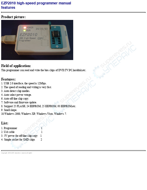
Product picture:Field of application:This programmer can read and write the bios chips of DVD,TV,PC,harddisk,etc. Features:1. USB2.0 interface, the speed is 12Mbps.2. The speed of reading and writing is very fast.3. Auto detect chip modles.4. Auto select power votage.6. Auto off-line chip copy.7. Software and firmware update.8. Surpport 25 FLASH, 24 EEPROM, 25 EEPROM, 93 EEPROM,etc.9. Small shape.10.Windows 2000, Windows XP, Windows Vista, Windows 7.List:1. Programmer 12. Usb cable 13. 5V power for off-line chip copy 14. Simple socket for SMD chips 2Copyright 2010-2015 elecm icro reserve all rights!This programmer supports all the 24, 25, 93 series memory chips!********************25 SPIFLASH******************************************************************* AMIC: A25L05P, A25L512, A25L010, A25L10P, A25L020, A25L20P, A25L040, A25L40P, A25L080, A25L80P, A25L016,A25L16P, A25L032ATMEL: AT25F512, AT25F512A, AT25F512B, AT25F1024, AT25F1024A, AT25FS010, AT25DF021, AT25F2048, AT25DF041A, AT25F4096, AT25FS040, AT26F004, AT26DF081A, AT25DF161, AT26DF161, AT26DF161A, AT25DF321, AT25DF321A,AT26DF321, AT25DF641EON: EN25F05, EN25LF05, EN25P05, EN25D10, EN25F10, EN25LF10, EN25P10, EN25D20, EN25F20, EN25LF20, EN25D40, EN25F40, EN25LF40, EN25D80, EN25F80, EN25Q80, EN25T80, EN25B16, EN25B16T, EN25D16, EN25F16, EN25Q16, EN25T16, EN25B32, EN25B32T, EN25F32, EN25P32, EN25Q32, EN25B64, EN25B64T, EN25F64, EN25P64, EN25Q64, EN25F128, EN25Q128 ES: ES25P10, ES25P20, ES25M40, ES25M40A, ES25P40, ES25M80, ES25M80A, ES25P80, ES25M16, ES25M16A, ES25P16,ES25P32ESMT: F25L004A, F25L04UA, F25L008A, F25L08PA, F25L016A, F25L16PA, F25L32PA, F25L32QAMXIC: MX25L512, MX25V512, MX25L1005, MX25L2005, MX25L4005A, MX25V4005, MX25L8005, MX25V8005, MX25L1605D, MX25L1635D, MX25L3205D, MX25L3225D, MX25L3235D, MX25L3237D, MX25L6405D, MX25L12805DNEXFLASH: NX25P10, NX25P20, NX25P40, NX25P80, NX25P16, NX25P32PMC: PM25LV512A, PM25LV010A, PM25LV020, PM25LV040, PM25LV080B, PM25LV016BSAIFUN: SA25F005, SA25F010, SA25F020, SA25F040, SA25F080, SA25F160, SA25F320SPANSION: S25FL004A, S25FL008A, S25FL016A, S25FL032A, S25FL064ASST: SST25VF512, SST25VF512A, SST25VF010, SST25VF010A, SST25VF020, SST25VF020A, SST25VF040, SST25VF040A, SST25VF040B, SST25VF080B, SST25VF016B, SST25VF032B, SST25VF064CST: M25P05A, M25P10A, M25PE10, M25P20, M25PE20, M25P40, M25PE40, M25P80, M25PE80, M25PX80, M25P16, M25PE16, M25PX16, M25P32, M25PX32, M25P64, M25PX64, M25P128WINBOND: W25P10, W25X10, W25X10A, W25X10AL, W25X10L, W25P20, W25X20, W25X20A, W25X20AL, W25X20L,W25P40, W25X40, W25X40A, W25X40AL, W25X40L, W25P80, W25X80, W25X80A, W25X80AL, W25X80L, W25P16, W25X16,W25P32, W25X32, W25X64********************24EEPROM******************************************************************* ATMEL: AT24C01, AT24C01A, AT24C01B, AT24C02, AT24C02A, AT24C02B, AT24C04, AT24C04A, AT24C04B, AT24C08, AT24C08A, AT24C08B, AT24C16, AT24C16A, AT24C16B, AT24C32, AT24C32A, AT24C32B, AT24C64, AT24C64A, AT24C64B, AT24C128, AT24C128A, AT24C128B, AT24C256, AT24C256A, AT24C256B, AT24C512, AT24C512A, AT24C512B, AT24C1024, AT24C1024A, AT24C1024BCATALYST: CAT24C01, CAT24WC01, CAT24C02, CAT24WC02, CAT24C04, CAT24WC04, CAT24C08, CAT24WC08, CAT24C16, CAT24WC16, CAT24C32, CAT24WC32, CAT24C64, CAT24WC64, CAT24C128, CAT24WC128, CAT24C256,CAT24WC256, CAT24C512, CAT24WC512, CAT24C1024, CAT24WC1024COMMON: 24C00 3V, 24C00 5V, 24C01 3V, 24C01 5V, 24C02 3V, 24C02 5V, 24C04 3V, 24C04 5V, 24C08 3V, 24C08 5V,24C16 3V, 24C16 5V, 24C32 3V, 24C32 5V, 24C64 3V, 24C64 5V, 24C128 3V, 24C128 5V, 24C256 3V, 24C256 5V, 24C512 3V,24C512 5V, 24C1024 3V, 24C1024 5VFAIRCHILD: FM24C01L, FM24C02L, FM24C03L, FM24C04L, FM24C05L, FM24C08L, FM24C09L, FM24C16L, FM24C17L, FM24C32L, FM24C64L, FM24C128L, FM24C256L, FM24C512L, FM24C1024LHOLTEK: HT24C01, HT24LC01, HT24C02, HT24LC02, HT24C04, HT24LC04, HT24C08, HT24LC08, HT24C16, HT24LC16,HT24C32, HT24LC32, HT24C64, HT24LC64, HT24C128, HT24LC128, HT24C256, HT24LC256, HT24C512, HT24C1024ISSI: IS24C01, IS24C02, IS24C04, IS24C08, IS24C16, IS24C32, IS24C64, IS24C128, IS24C256, IS24C512, IS24C1024 MICROCHIP: 24AA00, 24C00, 24LC00, 24AA01, 24AA014, 24C01C, 24LC014, 24LC01B, 24AA02, 24LC02B, 24AA024,24AA025, 24AA04, 24C02C, 24LC024, 24LC025, 24LC04B, 24AA08, 24LC08B, 24AA16, 24LC16B, 24AA32, 24LC32, 24AA64,24FC64, 24LC64, 24AA128, 24FC128, 24LC128, 24AA256, 24FC256, 24LC256, 24AA512, 24FC512, 24LC512, 24AA1024NSC: NSC24C02, NSC24C02L, NSC24C64RAMTRON: FM24C04A, FM24CL04, FM24C16A, FM24CL16, FM24C64, FM24CL64, FM24C256, FM24CL256, FM24C512 ROHM: BR24C01, BR24L01, BR24C02, BR24L02, BR24C04, BR24L04, BR24C08, BR24L08, BR24C16, BR24L16, BR24C32, BR24L32, BR24C64, BR24L64ST: ST24C01, ST24C02, ST24C04, ST24C08, ST24C16, ST24C32, ST24C64XICOR: X24C01, X24C02, X24C04, X24C08, X24C16********************93EEPROM******************************************************************* AKM: AK93C45AV, AK93C55AV, AK93C65AV, AK93C75AVATC: ATC93C46, ATC93LC46(16bit), ATC93LC46(16bit)-SOP8, ATC93LC46(8bit), ATC93LC46(8bit)-SOP8, ATC93C56,ATC93LC56(16bit), ATC93LC56(16bit)-SOP8, ATC93LC56(8bit), ATC93LC56(8bit)-SOP8, ATC93C66, ATC93LC66(16bit),ATC93LC66(16bit)-SOP8, ATC93LC66(8bit), ATC93LC66(8bit)-SOP8ATMEL: AT93C46(16bit), AT93C46(16bit)-SOP8, AT93C46(8bit), AT93C46(8bit)-SOP8, AT93C46A, AT93C56(16bit),AT93C56(16bit)-SOP8, AT93C56(8bit), AT93C56(8bit)-SOP8, AT93C57(16bit), AT93C57(16bit)-SOP8, AT93C57(8bit),AT93C57(8bit)-SOP8, AT93C66(16bit), AT93C66(16bit)-SOP8, AT93C66(8bit), AT93C66(8bit)-SOP8, AT93C86(16bit),AT93C86(16bit)-SOP8, AT93C86(8bit), AT93C86(8bit)-SOP8CATALYST: CAT93C46(16bit), CAT93C46(8bit), CAT93C46A, CAT93C46I, CAT93C56(16bit), CAT93C56(8bit), CAT93C56A, CAT93C57(16bit), CAT93C57(16bit)-SOP8, CAT93C66(16bit), CAT93C66(8bit), CAT93C66A, CAT93C86(16bit), CAT93C86(8bit) COMMON: 93C46(16bit), 93C46(8bit), 93C56(16bit), 93C56(8bit), 93C66(16bit), 93C66(8bit), 93C86(16bit), 93C86(8bit) EXEL: XL93C06, XL93C46, XL93CS46, XL93LC46, XL93C56, XL93LC56, XL93C66, XL93LC66FAIRCHILD: FM93C06AM8(16bit), FM93C06AM8(8bit), FM93C06M8, FM93C06N, FM93C46AM8(16bit),FM93C46AM8(8bit), FM93C46AN(16bit), FM93C46AN(8bit), FM93CS46(16bit), FM93C56AN(16bit), FM93C56AN(8bit),FM93CS56(16bit), FM93C66AM8(16bit), FM93C66AM8(8bit), FM93C66AN(16bit), FM93C66AN(8bit), FM93C66B,FM93C66M8(16bit), FM93C66MT8(16bit), FM93C66N(16bit), FM93CS66(16bit), FM93C86AM8(16bit), FM93C86AM8(8bit),FM93C86AN(16bit), FM93C86AN(8bit)HOLTEK: HT93LC46A(16bit), HT93LC46A(8bit), HT93LC56A(16bit), HT93LC56A(8bit), HT93LC66A(16bit),HT93LC66A(8bit)ICT: ICT93C46(16bit), ICT93C46(8bit), ICT93C56(16bit), ICT93C56(8bit), ICT93C66(16bit), ICT93C66(8bit)ISSI: IS93C46(16bit), IS93C56(16bit), IS93C66(16bit)MICROCHIP: 93C06(16bit), 93C06(16bit)-SOP8, 93AA46(16bit), 93AA46(8bit), 93AA46(8bit)-SOP8, 93C46(16bit),93C46(16bit)-SOP8, 93C46A, 93C46B, 93LC46(16bit), 93LC46(16bit)-SOP8, 93LC46(8bit), 93LC46(8bit)-SOP8, 93LC46A, 93LC46B, 93LC46B-SOP8, 93AA56(16bit), 93AA56(8bit), 93AA56(8bit)-SOP8, 93C56(16bit), 93C56(16bit)-SOP8, 93C56(8bit), 93C56(8bit)-SOP8, 93C56A, 93C56A-SOP8, 93C56B, 93C56B-SOP8, 93LC56(16bit), 93LC56(16bit)-SOP8, 93LC56(8bit), 93LC56(8bit)-SOP8,93LC56A, 93LC56B, 93LC56B-SOP8, 93AA66(16bit), 93AA66(8bit), 93AA66(8bit)-SOP8, 93C66(16bit), 93C66(16bit)-SOP8,93C66(8bit), 93C66(8bit)-SOP8, 93C66A, 93C66A-SOP8, 93C66B, 93C66B-SOP8, 93LC66(16bit), 93LC66(16bit)-SOP8, 93LC66(8bit), 93LC66(8bit)-SOP8, 93LC66A, 93LC66B, 93LC66B-SOP8, 93AA76(16bit), 93AA76(8bit), 93C76(16bit), 93C76(8bit), 93LC76(16bit), 93LC76(8bit), 93LC76A, 93LC76B, 93AA86(16bit), 93AA86(8bit), 93C86(16bit), 93C86(8bit), 93LC86(16bit), 93LC86(8bit), 93LC86A, 93LC86BNSC: NSC93C06, NSC93C06-SOP8, NSC93CS06, NSC93C46, NSC93CS46, NSC93C56, NSC93CS56, NSC93S56, NSC93C66, NSC93CS66, NSC93C86ROHM: BR93LC46, BR93LC46RF, BR93LC56, BR93LC56RF, BR93LC66, BR93LC66RFST: ST93C06, M93S46, M93S46-SOP8, M93S46-T8, M93S46R, M93S46R-SOP8, M93S46W, M93S46W-SOP8, ST93C46, M93S56, M93S56-SOP8, M93S56R, M93S56R-SOP8, M93S56W, M93S56W-SOP8, ST93C56, M93S66, M93S66-SOP8, M93S66R, M93S66R-SOP8, M93S66W, M93S66W-SOP8, ST93C66********************25EEPROM******************************************************************* ATMEL: AT25010, AT25020, AT25040, AT25080, AT25160, AT25320, AT25640, AT25128, AT25256, AT25512 CATALYST: CAT25C01, CAT25C01P, CAT25C01S, CAT25C01U, CAT25C02P, CAT25C02S, CAT25C02U, CAT25C03P, CAT25C03S, CAT25C03U, CAT25C04P, CAT25C04S, CAT25C04U, CAT25C05P, CAT25C05S, CAT25C05U, CAT25C08P, CAT25C08S, CAT25C08U, CAT25C09P, CAT25C09S, CAT25C09U, CAT25C16P, CAT25C16S, CAT25C16U, CAT25C17P, CAT25C17S, CAT25C17U, CAT25C32P, CAT25C32S, CAT25C33P, CAT25C33S, CAT25C64P, CAT25C64S, CAT25C65P, CAT25C65S, CAT25C128P, CAT25C128S, CAT25C256P, CAT25C256SCOMMON: 25010, 25020, 25040, 25080, 25160, 25320, 25640, 25128, 25256, 25512MICROCHIP: 25AA040, 25C040, 25LC040, 25AA080, 25C080, 25LC080, 25AA160, 25C160, 25LC160, 25AA320, 25C320, 25LC320, 25AA640, 25C640, 25LC640RAMTRON: FM25C160, FM25640, FM25CL64ST: ST25C01, ST25W01, ST25C02, ST25W02, ST25C04, ST25W04, ST25C08, ST25W08, ST25C16, ST25W16TI: TI2532, TI2532A, TI2564XICOR: XC25010, XC25020, XC25040, XC25080, XC25160, XC25320, XC25640, XC25128, XC25256, XC25512Copyright 2010-2015 elecm icro reserve all rights!software setupNo need to install, please run the *.exe programm. Copyright 2010-2015 elecm icro reserve all rights!driver setupThere are tow usb device driver files: EZP2010.inf and EZP2010.sys. The step of usb driver setup is same as other usb devices.Copyright 2010-2015 elecm icro reserve all rights!system requirementsSystem software requirements: Windows 2000,Windows XP,Windows Vista,Windows 7.System hardware requirements:USB1.0 interface.CD-ROM.64MB RAM.10MB harddisk space.Copyright 2010-2015 elecm icro reserve all rights!select chipUser can select chip modle from "Type", "Manu" and "Chip" combox. User can click "Search" to select chip modle too.Copyright 2010-2015 elecm icro reserve all rights!software UI1. Open File: Load data to buffer from file.2. Save File: Save data to file from buffer.3. Buffer Fill: Fill buffer to specified datas.4. Byte Swap: Swap the bytes in the buffer.5. Auto: Erase, write and verify.6. Erase: Erase chip.7. Write: Write data to chip from buffer.8. Read: Read data to buffer from chip.9. Verify: Compare the data in chip to the data in buffer.10.Detect: Detect chip modle.11.Version: Read firmware version.12.Update: Update firmware.13.Help: Open the user manual.14.About: View the version information of software. Copyright 2010-2015 elecm icro reserve all rights!editUser can change data in buffer. Copyright 2010-2015 elecm icro reserve all rights!Click "Search", then pop the above dialog, enter the keyword, the matched chips will be listed in the listbox. Copyright 2010-2015 elecm icro reserve all rights!Click "Detect", the software will pop a messagebox to show chip name. The programmer only can detect 25 series spi flash.Copyright 2010-2015 elecm icro reserve all rights!Load data to buffer from a bin file or a hex file. Copyright 2010-2015 elecm icro reserve all rights!Save data to a bin file from buffer. Copyright 2010-2015 elecm icro reserve all rights!firmware updateUser can click "Update" botton to update firmware.Select the correct update file (*.ezp), and the updating operation will complete in several seconds. If the operation is successful, the software will pop the messagebox as below:If the operation is unsuccessful, the software will pop the messagebox as below:First remove the programmer from PC, then click "OK", and link the programmer to PC again. Copyright 2010-2015 elecm icro reserve all rights!off-line copyThe programmer can copy one chip to another chip.When the programmer detects two chips on the socket, it will automatically start copying operation.1. When off-line copying, the programmer can link to 5V power as well as link to PC.2. The programmer can copy data to a 24 eeprom from another 24 eeprom.3. The programmer can copy data to a 25 flash from another 25 flash.4. The capacity of destination chip must be equal to source chip.Copyright 2010-2015 elecm icro reserve all rights!One 25 flash must be erased before writing.No need to erase one 24 eeprom before writting. No need to erase one 93 eeprom before writting.Copyright 2010-2015 elecm icro reserve all rights!Read data to buffer from chip. Copyright 2010-2015 elecm icro reserve all rights!Write data to chip from buffer. Copyright 2010-2015 elecm icro reserve all rights!Compare the data in chip to the data in buffer.It's necessary to execute the verify command after writting. Copyright 2010-2015 elecm icro reserve all rights!Erase, write and verify. Copyright 2010-2015 elecm icro reserve all rights!1. Verify error.(1)User must select a correct chip modle before writting.(2)User must erase chip before writting if che chip is a 25 flash.(3)User must select a correct memory unit width if che chip is a 93 eeprom.(4)The chip maybe bad.2. Chip position when reading and writting.(1)If the programmer is linked to PC, the chip must be placed in the socket as below:3. Automatically detect chip modle unsuccessful.See the section "detect chip" in this document.4. The simple SMD socket.The simple SMD socket has tow chip positions.User can place SMD chip on any one of the tow position.5. Read and write chips on the mainboard (ISP).User can link programmer to mainboard to read and write bios chips.User can link GND, CS, MISO, MOSI, CLK signals to mainboard.Copyright 2010-2015 elecm icro reserve all rights!。
- 1、下载文档前请自行甄别文档内容的完整性,平台不提供额外的编辑、内容补充、找答案等附加服务。
- 2、"仅部分预览"的文档,不可在线预览部分如存在完整性等问题,可反馈申请退款(可完整预览的文档不适用该条件!)。
- 3、如文档侵犯您的权益,请联系客服反馈,我们会尽快为您处理(人工客服工作时间:9:00-18:30)。
1
7-24C 题 7-23C 中,问水平冲量 I 应作用于杆 AB 何处时,铰点 A 的碰撞冲量为零,并求此时铰点 C 处的碰撞冲量。
难度系数 4/5
知识要点 动量矩定理和动量定理
A
C
I
B
题 7-23C
D
解: 如图所示建立参考基。 设冲量 I 作用点距 A 点 为 h。杆 AB、杆 CD 为定轴转动,杆 CD 为平动。 杆上所受冲量如图示。 以杆 AB 为研究对象,有 J Az1 J Az10 Ih I Bx l l l m( 1 10 ) I I Ax I Bx 2 2 以杆 BC 为研究对象,有 I Dx mvx mvx 0 I Bx
D
I Dx I Dy
(1) (2) (3) (4) (5) (6)
(7) (8)
洪嘉振等《理论力学》第 3 版习题详解
2
将题目要求 I Ay 0 与上式代入式(2)可解得
8 I 11 将式(8)与上式代入式(1)可解得使铰点 A 的碰撞冲量为零的外冲量作用的位置 10 h l 11 由式(4) , (5) , (7)与(8)可解得 1 1 I Cx ml1 I 6 11 I Bx
I Ax
h
I Ay
A
y
I Cx
I Cy
C
1 x I Bx I Dx2 ID
I Dy
B 以杆 CD 为研究对象,有 I By I By J Cz2 J Cz20 I Dx l l l I Bx m( 2 20 ) I Dx I Cx 2 2 B 其中 vx , I Dx I Dx I Bx I Bx 1 题解 7-23C J Az J Cz ml 2 3 由条件 10 20 v x 0 0 ,上面 5 个方程变为 1 2 ml 1 Ih I Bx l 3 1 ml1 I I Ax I Bx 2 mvx I Bx I Dx 1 2 ml 2 I Dx l 3 1 ml 2 I Dx I Cx 2 速度约束方程为 v x v Bx 1 l v x vDx 2 l 故 1 2 由式(1) 、 (3)与(4) ,考虑到式(6)与(7)可解得 6I 1 11ml
