RM4036通讯协议
MCU配置说明实现 施耐德 PLC MODBUS TCP

施耐德PLC MODBUS TCP说明1、通讯接口:以太网TCP\IP(MODBUS\TCP协议),MCU为客户端,主动连接PLC的502端口,当连接成功后,MCU定时轮循PLC的MW及M区,取得遥测、遥信数据,还可以把转发的YC、YX数据写到PLC内,可供PLC使用或者供HMI读(实现HMI上显示MCU上的其它装置上的数据)。
功能说明:操作员站具有遥信、遥测、总召、遥控(直控、选控)、遥调、校时、电度功能另外还可把其它装置的遥信、遥测数据转发给PLC以实现在HMI上显示其它装置的数据;无工程师站。
2、PLC寄存器说明:运行ModbusTCPMCU配置.exe,设置IP地址,连接,然后根据工程进行各项配置,设置即可。
注:每个MCU只能连1个施耐德PLC装置。
注:PLC各个区划分情况如下(以下寄存器地址以1为起始地址,如以0为起始地址,以下寄存器地址应均减1):遥测:%MW881~1200,每个寄存器存放一个量。
遥信:从%M1-4096,注意,DO紧跟在DI之后,具体DI、DO个数根据现场需要和PLC程序可用ModbusTCPMCU配置.exe进行设置。
电度:%MW1801~%MW1856,最多只能有56个寄存器(28个电度,两个寄存器表示一个电度)。
遥调:%MW736(点号)%MW737、%MW738(数据,标准float格式)直控:% MW757(点号)%MW758(命令,合(2)/分(1))选控:%MW768(点号)%MW769(命令,合(0xAA)/分(0x55))%MW770(返校标志,允许(0xF0)/不允许(0x0F))%MW771(命令,执行(0x80)/撤消(0xA0))校时:%MW730~%MW735%MW730、%MW731 0x0001%MW732 月年%MW733 时分%MW734 秒分%MW735 空(0)星期(0)时间为BCD码格式。
遥测转发写地址:%MW1001~%MW1065(可通过配置软件任意设定)遥信转发写地址:%MW1070~%MW1582(可通过配置软件任意设定)如查询从%MW881寄存器开始的遥测量,则其下发报文的起始地址应为:0x0370。
08-第8章 信令数据
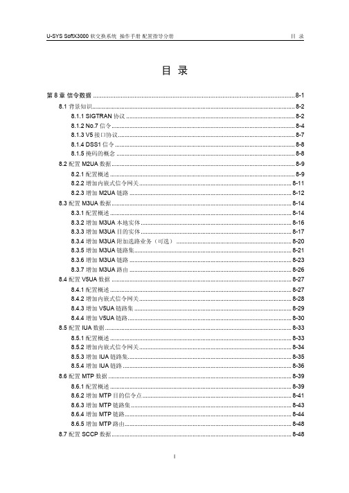
目录第8章信令数据.....................................................................................................................8-18.1 背景知识.............................................................................................................................8-28.1.1 SIGTRAN协议........................................................................................................8-28.1.2 No.7信令.................................................................................................................8-48.1.3 V5接口协议.............................................................................................................8-78.1.4 DSS1信令...............................................................................................................8-88.1.5 掩码的概念..............................................................................................................8-88.2 配置M2UA数据.................................................................................................................8-98.2.1 配置概述..................................................................................................................8-98.2.2 增加内嵌式信令网关..............................................................................................8-118.2.3 增加M2UA链路....................................................................................................8-128.3 配置M3UA数据...............................................................................................................8-148.3.1 配置概述................................................................................................................8-148.3.2 增加M3UA本地实体.............................................................................................8-168.3.3 增加M3UA目的实体.............................................................................................8-178.3.4 增加M3UA附加选路业务(可选).......................................................................8-208.3.5 增加M3UA链路集.................................................................................................8-218.3.6 增加M3UA链路....................................................................................................8-238.3.7 增加M3UA路由....................................................................................................8-268.4 配置V5UA数据...............................................................................................................8-278.4.1 配置概述................................................................................................................8-278.4.2 增加内嵌式信令网关..............................................................................................8-288.4.3 增加V5UA链路集.................................................................................................8-298.4.4 增加V5UA链路.....................................................................................................8-308.5 配置IUA数据...................................................................................................................8-338.5.1 配置概述................................................................................................................8-338.5.2 增加内嵌式信令网关..............................................................................................8-348.5.3 增加IUA链路集.....................................................................................................8-358.5.4 增加IUA链路........................................................................................................8-368.6 配置MTP数据.................................................................................................................8-398.6.1 配置概述................................................................................................................8-398.6.2 增加MTP目的信令点............................................................................................8-418.6.3 增加MTP链路集...................................................................................................8-438.6.4 增加MTP链路.......................................................................................................8-448.6.5 增加MTP路由.......................................................................................................8-488.7 配置SCCP数据...............................................................................................................8-488.7.1 配置概述................................................................................................................8-488.7.2 增加SCCP远端信令点.........................................................................................8-508.7.3 增加SCCP子系统.................................................................................................8-528.7.4 增加新全局翻译码(可选)...................................................................................8-548.7.5 增加全局翻译码(可选).......................................................................................8-55 8.8 配置V5接口数据.............................................................................................................8-578.8.1 配置概述................................................................................................................8-578.8.2 增加V5接口..........................................................................................................8-598.8.3 增加V5变量(可选)...........................................................................................8-63 8.9 配置PRA链路数据..........................................................................................................8-648.9.1 配置概述................................................................................................................8-648.9.2 增加PRA链路.......................................................................................................8-66第8章信令数据本章所描述的信令数据主要包括M2UA数据、M3UA数据、V5UA数据、IUA 数据、MTP数据、SCCP数据、V5接口数据、PRA链路数据以及ISUP适配数据,配置信令数据必须在配置完硬件数据与媒体网关数据之后进行,如图8-1所示。
智能卡网吧收费机设计1

适 用
多存储器结构: 多种安全措施,可充值,单应用 宾馆门禁、加油卡等小额电子钱包 单存储器多分区结构:支持一卡多用,可充值 一卡通
多存储器逻辑加密卡—SLE4442
按字节操作,可反复应用 多存储器结构
256 *8位 EEPROM型主存储器。 32 *1位 PROM型保护存储器。 4 * 8位 EEPROM型加密存储器
产品开发之第一步:网吧卡选型
智能卡网吧收费系统卡型需求分析 • 小额电子钱包功能,脱机消费(无需 与银行联网消费),可以充值 • 定额收费 • 防伪造,防非法充值 • 单一应用,低成本
网吧卡选型——存储卡
AT24C**系列存储卡是否适合用于网吧收费收 费系统?为什么?
否! 存储卡无任何安全措施 易被伪造、非法充值
安全性:用户密码(3字节)+密码错误计 数(3次)+PROM保护 2线串行连接协议,满足 ISO7816同步传 送协议
SLE4442存储结构
地址
255 I/O 读 224字节未保护 数据存储器 加密逻辑 可编程 加密代码 错误计数器 保护存储 器 PROM 32字节保护数 据存储器 (厂商代码) 32 31
实训 接触式逻辑加密卡读写操作
准备: 按设备说明书完成以下准备与测试工作 连接串行通信线: 连接实训箱电源: 通信测试: 卡型测试:
SLE4442读写操作
读卡:记录卡密码、卡错误计数值,主存储器存储结构 (各区域名称、地址范围、字节数)、存储内容和读出条 件。 写卡:对主存储器各区域进行写入/擦除操作,记录操作 结果,总结各区域写入/擦除条件。 密码操作:试验用SLE4442卡密码:FFFFFFH (1)修改密码:在未通过和已通过密码校验二种情况下 分别修改密码,记录操作结果,总结修改密码的条件。 (2)恶意猜测密码:在未通过密码校验的情况下输入错 误密码,记录此时的读卡、写卡结果。 注意: 修改密码后必须及时还原密码为FFFFFFH。 猜测密码错误次数不得超过2次!以免锁卡!
施耐德rm6

1.PRESENTATION概述The RM6 is a "totally SF6" switch-gear range with built-in functions and reduced dimensions.This self-contained totally insulated unit constitutes the MV component of the MV/LV transformer substation or the branching point of an MV network. The RM6 regroups, in a single metal enclosure,all the medium voltage functions enabling transformers to be connected, supplied and protected.RM6是一种“全部SF6化“的开关设备,具有组合功能和小型化的特点。
该密封式全绝缘的装置单元,组成中压/低压配电站内的中压元件,RM6组装所有的中压回路在一个金属外壳内,并能连接至变压器,对其进行供电和保护。
2. QUANTITATIVE DESCRIPTION 设备说明3. STANDARDS 标准RM6 is fully type tested in accordance with relevant Chinese standard(GB) in Xian, (type test report No.98 497).The equipment proposed in this offer has been designed, manufactured and tested in compliance with IEC recommendations.RM6 完全满足中国GB标准,已通过西安型式试验,见试验报告编号NO 98 497本设备按照IEC标准的要求进行设计,制造及试验,详细标准如下:∙Common clause for high voltage switchgear and low voltage switchgear IEC 694 高低压开关装置公共条款∙Self-contained medium voltage apparatus 中压成组装置设备IEC 298∙High voltage circuit breakers 高压断路器IEC 56∙AC switches and earthing switches 交流负荷开关和接地开关IEC 129∙Switches and disconnectors 负荷开关和隔离开关IEC 265∙Combined switch/disconnectors 组合式负荷开关/隔离开关IEC 420∙High voltage fuses 高压熔断器IEC 282∙Classification of degrees of protection for enclosures 外壳防护等级标准 IEC 529∙Chinese electric standard 中国电气标准∙高压负荷开关标准GB3804∙金属封闭开关设备标准GB3906∙高压开关设备通用技术条件GB11022—89∙电力部负荷开关标准DL4044. GENERAL CHARACTERISTICS IN ACCORDANCE WITH THE IEC STANDARDS 4.1. General characteristics 主要技术参数4.2.Electrical characteristics 电气参数♦In accordance with IEC recommendations, these characteristics are valid for ambient temperatures between -25°C and +40°C.其满足IEC标准,这些参数适应-25︒C---+40︒C 环境温度。
[BPS-i100]PL-4036-00 RevI BPS-i100 Manual
![[BPS-i100]PL-4036-00 RevI BPS-i100 Manual](https://img.taocdn.com/s3/m/500cfb631711cc7931b71630.png)
BPS-i1001.6 bar (23.2 psi)20 liters/min (5.3 gallons/min) USER MANUALTable of Contents1SAFETY PRECAUTIONS (3)2SPECIFICATIONS (4)2.1Specification of Components (4)2.2System Overview and General Specification (6)2.2.1Standard System Configuration for Speed Control (6)2.2.2Standard Configuration for Process Control (6)2.3General Environmental Conditions (7)2.4Pressure-Flow Curves (8)2.5Maximum Static Pressure for Pump Heads (8)2.6Basic Dimensions of Main Components (9)3ENGINEERING INFORMATION (10)3.1Sealing and Material Concept (10)3.2Power Supply and Consumption (11)3.2.1Power Consumption (11)3.2.2Inrush Current (11)3.2.3Back EMF (11)3.3Temperature Monitoring (11)3.4Thermal Management (12)3.5Hydraulic Circuit Design (14)4INSTALLATION (15)4.1Electrical Installation (15)4.1.1Overview Wire Designation of Driver Cable (15)4.1.2Overview Electrical Schematics of Driver Interface (16)4.1.3Installation Instructions for Power Supply (17)4.1.4Installation PLC Interface Signals (17)4.1.5Installation of RS485 Interface (17)4.1.6Installation of RS485 Fieldbus Multi-Pump System Arrays (18)4.2Mechanical Installation (18)5OPERATION (19)6INSPECTION AND MAINTENANCE (21)6.1Replacement Interval of the Impeller (21)6.2Impeller Replacement Procedure (21)6.2.1Preparation (21)6.2.2Instructions for Replacement (22)7TROUBLESHOOTING (23)7.1Troubleshooting for Operation with Driver (23)7.2Troubleshooting with Service Software (23)8TECHNICAL SUPPORT (23)9APPENDIX (24)9.1Regulatory Status (24)9.1.1CE Marking (24)9.2Symbols and Signal Words (25)1 Safety PrecautionsThe BPS-i100pump system is designed to be used in industrial production machines and equipment containing hydraulic circuits. Typical applications are Semiconductor and chemical manufacturing equipment. Installation shall be done by qualified personnel only. Followin g safety precautions and all “CAUTION”, “WARNING” and “DANGER” indications in the relevant sections shall be followed.High magnetic fieldThealter or damage the calibration of sensitive electronic devices and measuring instrumentscomputers,cards, audio and video tapes etc.)Hazardous voltage may be present.Inmay be present (even if the system is designed for up to 24 VDC). The usage of a galvanic separated power supply, which is certified by a 3CE), is highly recommended.Do not under any circumstances open the powered driver.High magnetic field strength of pump impeller.The strength. Pacemakers may be influenced and magnetic forces may lead to contusions. Keep distance to pacemakers and handle impeller with care.TOXIC CHEMICALS may be present.When using the system to pump chemicals skin contact and toxic gases may be hazardous to your health. Wear safety gloves and other appropriate safety equipment.2 Specifications2.1 Specification of ComponentsFigure 1 shows the main system components (driver and pump head) and Figure 2 illustrates the accessories for the pump system.Figure 1: Pump system with main standard componentsFigure 2: Accessories43a3b3c3e3d5a5c5b2a12bTable 1: Standard system configurationsTable 2: Specification of standard components1: Kalrez® is a registered trademark of DuPont Dow Elastomers. 2: Designed and tested for IP67.Table 3: Specification of accessories2.2 System Overview and General Specification2.2.1 Standard System Configuration for Speed ControlWhen using the pump system in speed control mode, the speed can precisely be set via an analog input. Various digital inputs and outputs allow controlling and monitoring of the system. A RS485enables communication with a PC with the Levitronix®Service Software 2.0. Hence parameterization, firmware updates and failure analysis are possible. The RS485can also be used as a fieldbus to implement more intelligent concepts of pump control.Figure 3: Standard system configuration for speed control (details in Section 4.1.1)2.2.2 Standard Configuration for Process ControlThe PLC interface of the BPS-i100 pump system enables the implementation of precise closed loop flow or pressure control in connection with either a flow or pressure sensor (see Figure 4). Precise ultrapure flow control systems can be realized with the BPS-i100pump system in combination with LEVIFLOW®flowmeters.- PLC:Figure 4: Standard system configuration for process control(Pressure or flow control with external sensor, details in Section 4.1.1)2.3 General Environmental ConditionsTable 4: Environmental conditions for pump systemFigure 5: Pressure/flow rate curves(Measured with pump head LPP-200.7)2.5 Maximum Static Pressure for Pump HeadsFigure 6: Specification for maximum static pressure of pump head LPP-200.7 (Pressure limits only valid for pump head mounted on motor)2.6 Basic Dimensions of Main ComponentsFigure 7: B asic dimensions (in [mm] and [inch]) of driver IPD-100.2-50 with pump head LPP-200.7(For other configurations refer to according drawings)Table 5: Specifications for min. bending radius of driver cableNote: If not mentioned explicitly all the cables are not suited for constant dynamic bending and movement!6pcs M4x16 Screws (SS PTFE coated, torque spec. 20 Ncm) (For inner pump housing)Tube ½“8pcs M3x40 Screws (SS PTFE coated, torque spec: 15 Ncm)(For pump head motor mounting. Pump head can be rotated by 45 degree)Cable outer diameter (OD): < 8 mm Standard length: 5m, open wires3 Engineering Information3.1 Sealing and Material ConceptFigure 8: Sealing and material concept (Driver IPD-100.1/2-50 with pump head LPP-200.7)Table 6: Materials used in the IPD-100.1/2-50 drivers and LPP-200.7 pump head(For other configurations refer to according specifications and drawings)83.2 Power Supply and Consumption3.2.1 Power ConsumptionFigure 9: Electrical power consumption(Pump head LPP-200.7 with driver IPD-100.2-50)3.2.2 Inrush CurrentWhen selecting an AC/DC power supply, the inrush currents (currents during power-on) shown in Table 7 shall be considered. If the specifications of the power supply are unclear a test with multiple power-on cycles is recommended to assure proper operation.Table 7: Inrush currents of power supply to driver during power on (Measured at 24 VDC + 10%)3.2.3 Back EMFDuring dynamic situations like braking of the impeller the back EMF of the driver can cause over-voltages. A power supply should be able to handle an overvoltage of +10% during 100 ms. If the power supply specifications are unclear a dynamic test with multiple braking from maximum speed is recommended.3.3 Temperature MonitoringTo avoid overheating of the system, the controller and motor temperatures within the driver are monitored. If one of both temperatures exceeds 80 °C (158 °F) for a duration of more than 10 minutes, the system goes into an error state and the pump stops. At 90 °C (176 °F), the system stops immediately.If 65 °C is exceeded a warning is given within the driver announcing to the user that the driver is running near the thermal limit (see explanation in Section 3.4). The warning signal can be monitored with the Levitronix® Service Software 2.0 or configured on one of the digital outputs.3.4 Thermal ManagementThe driver temperature depends on the ambient and liquid temperature, as well as on the hydraulic operation point. Figure 10, Figure 11 and Figure 12 illustrate the temperature characteristics of the motor depending on these parameters.Figure 10: Temperature curves for the IPD-100.2-50 driver @ 25 °C liquid temperature(Pumping with pump head LPP-200.7, temperature is measured inside of the integrated motor and controller,contact temperature of surface is below this temperature)Figure 11: Temperature curves for the IPD-100.2-50 driver @ 70 °C liquid temperature(Pumping with pump head LPP-200.7, temperature is measured inside of the integrated motor and controller,contact temperature is below this temperature)Figure 12: Influence of liquid temperature on driver temperature(Measurement at 6000 rpm 10 l/min but gradient is representative for other operational points)The above curves are measurements of the motor temperature at certain liquid and ambient temperatures. Equation (Eq. 1) shows how to calculate the motor temperature for other liquid and ambient temperatures based on these curves.In order to account for thermal variations (like ambient temperature, closed chemical cabinets or corners without ventilations) and to not significantly reduce the MTBF of the motor it is recommended to keep about 15 °C safety distance to the absolute thermal limit of the driver (80 °C) when designing the thermal concept of the pump system.It is recommended to avoid thermal stagnation in the room or cabinet where the driver is placed. Any type of circulation decreases the driver temperature significantly.3.5 Hydraulic Circuit DesignFollowing general design rules for the hydraulic circuit shall be considered for a robust operation of the pump system and optimum priming behavior:1. The general rule for optimum priming behavior is to minimize the pressure drop in the inlet circuit and avoidnegative pressure at the inlet of the pump head. 2. Minimize tubing length at the inlet of the pump head and maximize the ID (not smaller than the pump headinlet ID of 9.5 mm for LPP-200.7 is recommended). This reduces the pressure drop and the tendency of cavitation. 3. Avoid any restrictions, valves, elbows, bended tubing and sharp edges at the inlet circuit of the pump head,which potentially causes cavitation resulting in gas bubble collection in the pump head with the danger of priming loss. 4. Place the pump at the lowest point of the hydraulic circuit. Optimum is as much as possible below a tank orreservoir. This optimizes priming behavior and removal of gas bubbles. 5. Keep the liquid level in the reservoir tank or bag as high as possible, which increases the inlet pressure ofthe pump head and minimizes heat-up of the liquid. 6. In general the pump system placement and circuit shall be designed in a way that gas bubbles can leave thepump housing and that the pump head remains primed. 7. To minimize heat-up of the liquid the overall pressure drop in the hydraulic circuit shall be reduced as muchas possible. 8. It shall be avoided to pump longer times against a closed valve, which can cause heat-up of the liquid. 9. At flows < 1 l/min it is recommended to use a bypass loop to assure that sufficient flow runs through thepump head to wash-out gas bubbles. 10. There are specific pump heads, which are optimized for better priming and bubble robustness behavior andothers, which are optimized for higher viscosity and density. Select the suitable one according to Table 2. 11. At higher liquid temperature above rules become more important due to higher cavitation tendency of theliquid. 12. Load and stress at the inlet and outlet by heavy tubing and inexact mounting alignment shall be avoided(see Figure 13) as this can cause leakage issues due to distortion of the plastic pump housing.Figure 13: Avoidance of stress forces and torques at the inlet and outlet of the pump headContact the Levitronix ®Technical Service department (see Section 8) for more detailed considerations and support on the design of the hydraulic circuit.Tubing fixation/support to avoid load at in- and outlet of pump system.PumpHeavy tubing at in- and outlet of pump4 Installation4.1 Electrical Installation4.1.1 Overview Wire Designation of Driver CableTable 8: Signals of the driver cable with designation for standard firmware G1.48 - For other configurations of PLC Inputs and Outputs refer to alternate firmware documentation- Configurations can be done with Levitronix® Service Software 2.0 (see Manual with Doc.# PL-4034-00)- Power wires (P+, P-) have cross section 1.5 mm2 and all others 0.14 mm21: Standard cable is UL cable with according labelling on jacket. Non-UL cable is former version.4.1.2 Overview Electrical Schematics of Driver InterfaceFigure 14: Electrical schematics of driver interfacing- RS485/USB converter cable with termination resistors to be ordered according to Table 3- Do not use multiple master devices on the RS485 at the same time- Wire colours are defined for UL-cable. For non UL cable see Table 8.4.1.3 Installation Instructions for Power SupplyHazardous voltage may be present.Always isolate the electrical power supply before making or changing connections to the unit.In voltages may be present (even if the system is designed for 24 VDC). The usage of a galvanic separated power supply, which is certified by a 313. Depending on the required hydraulic operational point (see Figure 5), the pump system requires24V with a maximum power of 100 W. At a lower performance power supplies with smaller power or bigger supplies to supply several pump systems simultaneously may be used. Consult Figure 9 to get the power consumption depending on the flow. If other power supplies than theones recommended by Levitronix ®are used it is highly recommended to test these under dynamic conditions (acceleration and braking of the pump rotor speed). 14. Make sure that the polarity is correct and that AC/DC power supply is off.4.1.4 Installation PLC Interface SignalsTo operate the pump system with a PLC the analog input can be used to set either the speed or the process value (flow or pressure). The digital and analog outputs can be used to monitor the pump status and operating parameters (see Table 8).1. Power off the system2. Connect the designated wires of the driver cable according to Table 8. Assignments and functions of the I/Os can be changed with the controller firmware version (refer to according firmware documentation).3. Follow Figure 14 as reference for hardware configuration of the PLC in/outputs.4. Protect the un-used wires against short-circuit to each other.4.1.5 Installation of RS485 InterfaceFor usage of the RS485 as a control or service interface, an initialization resistor network according to Figure 14 or Figure 15 shall be used in order to have a stable communication and avoid disturbance effects. TheRS485 protocol for master communication is available at Levitronix ®on request.For Service and Debugging purposes with the Levitronix ®Service Software 2.0 and PC a USB/RS485 converter cable with integrated initialization resistors can be ordered according to Table 3. Do not use multiple master devices at the same time.4.1.6 Installation of RS485 Fieldbus Multi-Pump System ArraysFigure 15 shows a multi-pump system arrangement with the RS485 fieldbus and its basic specifications.Figure 15: Multi-pump system arrangement with RS485 fieldbusFollowing points and information shall be considered:→Testing has been done with arrangements of 8 pump systems. Higher number is possible but it is recommended to contact Levitronix® Technical Service department (see Section 8)for details and support.→Address setting of the pump units can be done with the Levitronix® Service Software 2.0 anda PC. A USB/RS485 converter cable with integrated initialization network can be orderedaccording to Table 3.→The RS485 protocol for master communication is available at Levitronix® on request.→Do not use multiple master systems at the same time.→Do not use closed ring arrangements.4.2 Mechanical InstallationThe driver can be fixed with four screws on the motor feet (see Figure 7). Mounting can be done in either in horizontal or vertical position.When mounting the pump head fittings into a circuit it has to be taken care that no mechanical stress is acting on the fittings, which can result in distorting creeping effects.5 OperationFigure 16: PLC interface state diagram for standard firmware G1.48(For other configurations refer to alternate firmware documentation)State “Off”:The pump system is switched off and the motor has no power. In this state, Levitronix® Service Software 2.0 has full control.State “ON” (speed control mode):The pump system is switched ON and the impeller is rotating with the referenced speed. The motor has electrical power when in this state.State “ON” (process control mode):The pump system is switched ON and the impeller is rotating with the referenced flow/pressure. The motor has electrical power when in this state.On (Priming mode):The pump system is switched ON and the impeller is rotating with the priming speed. The motor has electrical power when in this state. This mode can only be accessed by activating priming feature within EEPROM-editor in Levitronix®Service Software 2.0. Priming speed and timeout can also be configured within EEPROM-editor.State “Error”:If an error according to Table 9occurs in the pump system, the system defaults to the Error state. The according digital output on the PLC Interface Module is activated. The pump system is switched OFF. By a pulse off 300-700 ms on the Enable/Reset input the system gets back to the Off state.Table 9: Errors with indication on PLC interface for standard firmware G1.48(For other configurations refer to alternate firmware documentation)6 Inspection and Maintenance6.1 Replacement Interval of the ImpellerThe impeller has a limited lifetime depending on the chemical type, concentration and temperature of the fluid which is pumped. Therefore a preventive periodical exchange of the impeller is recommended. Contactthe Levitronix ®Technical Service Department (see Section 8) for further information on replacement times.6.2 Impeller Replacement Procedure6.2.1 PreparationBefore starting the impeller replacement procedure the parts and tools illustrated in Figure 17 and Figure 18 should be prepared. Impeller exchange kits, which contain these parts and tools areavailable at Levitronix ®(see Table 3). Please verify that you have the right types of impellers, O-rings and screws.Figure 17: Explosion view of pump head with driverFigure 18: Components for impeller replacement The following warnings and cautions should be read carefully before starting the replacement of the impeller.Integrated Pump DriverPump Casing BottomO-RingImpellerPump Housing LidPump Motor ScrewsPump Housing ScrewsPump HousingScrewsO-RingImpellerExchange ToolPump MotorScrewsReinforcing Cup6.2.2 Instructions for Replacement1. Power down the pump system and remove theAC power. If necessary, allow the housing to cool down to a workable temperature.2. Unscrew the pump motor screws. Remove thereinforcing cup and unscrew the pump head screws and remove the lid with the sealing ring.3. Remove the impeller with the ImpellerExchange Tool. Hook the claws of the Impeller Exchange Tool into two opposing orifices of the impeller.4. Inspect the wet area of the pump headcarefully. In case of material damage, also replace the pump casing.5. Place the new impeller into the pump casingusing the Impeller Exchange Tool. 6. If necessary, remove the existing O-Ring andgently press the new O-Ring into the lid of the pump casing.7. Press the lid with the O-Ring flush into thebottom of the pump casing.8. Carefully tighten the 6 pump head screws. Thescrews should not be used to press the lid with the O-ring into the bottom of the pump casing.Do not apply too much torque. The torque specification is:Torque for Stainless Steel M4: 20 Ncm9. Mount the reinforcing cup and tighten the 8pumpmotor screwswithfollowing torque specification:Torque for Stainless Steel M3: 15 Ncm10. S tart up the system and check if the impeller isrotating properly and the pump head doesn’t leak.11. I f the pump head leaks, check and make surethe lid and the O-Ring are properly pressed into the bottom of the pump casing. It may be necessary to change the O-Ring if it has been damaged.7 Troubleshooting7.1 Troubleshooting for Operation with DriverThe integrated PLC provides a Status and Error signal feedback according to Table 9. However, the source of error cannot be identified by these signals.For more detailed analysis the Levitronix® Service Software 2.0 can be used with a PC and a USB to RS485 interface cable.7.2 Troubleshooting with Service SoftwareThe Levitronix® Service Software 2.0 allows communication with the pump system in connection with a PC and a USB interface. The USB to RS485 adaptor cable as specified in Table 3can be used to setup communication.The software can be used for performing detailed troubleshooting. For usage of the Service Software refer to the Service Software User Manual (Document #: PL-4043-00), which is available in the download section on the Levitronix® web-page or contact the Levitronix®Technical Service Department (see under Section 8).8 Technical SupportFor troubleshooting, support and detailed technical information contact Levitronix®Technical Service Department:9 Appendix9.1 Regulatory Status9.1.1 CE MarkingWe herewith declare that the Centrifugal Pump System Family BPS-i100, in its various configurations, is in conformity with the below mentioned European Directives.Machinery Directive 2006/42/EC:The machinery directive essentially has been followed by a risk analysis, according mitigation actions and a user manual for safe operation. For the design and testing the following standards are used as a guideline:EN809 Pumps for Fluids: basic requirements are followed.EN12162 Procedure for hydrostatic pressure testing in fluid pumps: used for max. pressure testing of pump head.ISO12100 Safety for machinery – principles for risk assessments: used for system risk analysis.EMC Directive 2014/30/EC:The following standards of the EMC directive are tested and confirmed at a certified laboratory:EN61000-6-2 Generic standards, Immunity for industrial environmentsEN61000-6-4 Generic standards, Emission standard for industrial environments9.2 Symbols and Signal WordsToxic material, poisonCorrosive material, corrosionCut/sever hand, sharp objectStrong magnetic fieldDanger: electricity, electrical hazardWear safety glovesWear face shieldNo pacemakersATEX LogoTable 10: Safety symbols and signal words。
天融信脆弱性扫描与管理系统-快速安装与使用手册

天融信脆弱性扫描与管理系统快速安装与使用手册二O一三年六月天融信脆弱性扫描与管理系统--快速安装与使用手册目录第一章部署要求 (1)第二章使用需求 (2)第三章系统使用 (3)3.1系统登陆 (3)3.2用户管理 (3)3.3系统管理 (5)3.4任务管理 (6)第四章声明 (13)第一章部署要求天融信脆弱性扫描与管理系统连接网管交换机或者中心交换机上,进行网络安全评估,比如小型机、PC SERVER、网络设备(交换机、路由器等)、安全设备(如防火墙)及各工作站系统,进行周期性的安全扫描,得出评估分析报告,然后进行相应的漏洞修补或重新设计安全策略,以达到网络中硬件设备系统和应用平台的安全化。
●控制台的操作系统要求:无特殊要求,安装有通用浏览器(Firefox/IE)的操作系统均可,推荐操作系统Windows XP/server2003/Vista/Win7/Server2008;●控制台硬件性能要求:最低配置Pentium4或更高性能CPU;1GB 或更高容量的内存●控制台浏览器要求:系统安装有火狐(FireFox)3.0以上版本(推荐使用该浏览器)或者安装有IE6.0以上版本(IE7/IE8等)的浏览器;●产品出货形式:硬件工控机+相关文档+相关附件;3.1 系统登陆通过WEB方式配置硬件的具体操作步骤如下:1.将设备的eth0口用一根网线连到本地的交换机上,或者直接连到一台普通PC的网口上。
eth0口IP为192.168.1.254并以此类推eth1为192.168.2.254等等。
明确好管理IP 后,即可进行首次登录。
2.在浏览器的地址栏输入打开管理界面登录。
3.在进入登录界面前会弹出安全警报对话框,如下图所示:4.点击“是”,即可进入登录界面,如下图所示:默认管理账户:通过输入具有不同权限的用户名以及相应的密码便可以进入TopScanner系统的主界面(登陆用户可参照天融信脆弱性扫描与管理系统-用户手册),执行相应的操作。
力控组态软件6.1与施耐德M340 modbus tcp

根据以上工艺需求,定义5个点参数:
(1)反映集水井的液位模拟I/O点,点的名称定为“SY”。 (2)1号泵的工作状态B1。 (3)2号泵的工作状态B2。 (4)手动控制2号泵的运行按钮,命名为“RUN”。 (5)手动控制2号泵的停止按钮,命名为“STOP”。
数据连接
(1)继续在数据库组态程序话框:
力控组态软件6.1 与 施耐德M340 PLC 通过 modbus TCP 通信
声明• 本文件原文件来源于,作者仅作 部分修改 • 本文件不得用于商业目的 • 如使用本文件教学,请教师亲手演示,勿 要误人子弟或作大忽悠 • 不遵守以上要求及以下要求者,保留追诉 权利及网络公布、媒体公布的权利
文本制作
选择工具箱“文本”工具,在存储 罐上面单击一下变成文本输入模式, 输入“存储液位罐”然后按回车键 结束了第一个字符串,或者直接鼠 标在工具栏上空白处点击一下即可 退出文本模式。然后您可以输入另 外几个字符串“入口阀门”、“出 口阀门”和“传感器”。 效果如 下页
按钮制作
如图,仍然是在工具箱,点击“增强型按 钮”,鼠标箭头变成十字星,在窗口上即 可绘制按钮。绘制完毕再点击工具箱-“箭 头”退出按钮绘制
三、创建第一个简单工程实例
1、启动力控工程管理器,出现工程管理器窗口 如需打开原有文件,点击“开发”按键即可,如 需新建工程,点击“新建”按键
2、单击“新建”按钮,创建一个新的工程。 出现如图所示的应用定义对话框
1、使用新建...新建 一个工程,也可以试 试模板 2、输入要项目名称
3、选择生成路径,即 你的工程要保存的位 置,默认在C盘 4、描述信息可以不要
(2)在“设备”下拉框中选择设备,选择“M340”,再单击 “增加”按钮,出现如图所示仪表仿真驱动对话框。内存区 HR,使用的命令是03,偏置为0,即400001:0,对应于%MW0
多协议格式电子标签读写器用户手册 V3.3

多协议格式电子标签读写器用户手册V3.3多协议格式电子标签读写器用户手册V3.3 目录1.串行通讯接口规格 (1)2.协议描述 (1)3.数据块的格式 (2)<1> 命令数据块 (2)<2> 响应数据块 (2)4.命令执行结果状态值(Status)列表 (3)5.错误代码(error_code)定义 (6)5.1 ISO15693协议操作出错扩展代码(响应数据块的status=0x0F) (6)5.2 ISO14443A协议操作出错代码(响应数据块的status=0x10) (6)5.3 ISO14443B协议操作出错代码(响应数据块的status=0x1B) (7)6.操作命令的详细描述 (7)6.1读写器自定义命令 (7)6.1.1获得读写器的信息—Get Reader Information (7)6.1.2 关闭感应场—Close RF (8)6.1.3打开感应场—Open RF (8)6.1.4写入读写器地址—Write Com_adr (8)6.1.5写入询查命令最大响应时间—Write InventoryScanTime (8)6.1.6设置读写器为ISO14443A模式—ChangeToISO14443A (9)6.1.7设置读写器为ISO15693模式—ChangeToISO15693 (9)6.1.8 控制LED输出—SetLED (9)6.1.9 控制蜂鸣信号—Beep (9)6.1.10设置读写器为ISO14443B模式—ChangeToISO14443B (10)6.2 ISO15693协议命令 (10)6.2.1询查命令—Inventory (10)6.2.2静默模式—Stay Quiet (13)6.2.3读取指定块的数据—Read Single Block (13)6.2.4向指定块写入数据—Write Single Block (14)6.2.5永久锁定指定的块—Lock Block (15)6.2.6读取多个块的数据—Read Multiple Block (15)6.2.7进入“被选定selected状态”—Select (16)6.2.8返回“准备状态”—Reset to Ready (16)6.2.9写入应用类型识别码—Write AFI (16)6.2.10锁定应用类型识别码—Lock AFI (17)6.2.11写入数据保存格式识别码—Write DSFID (18)6.2.12锁定数据保存格式识别码—Lock DSFID (18)6.2.13获得电子标签的详细信息—Get System Information (19)6.3 ISO14443A协议命令 (20)6.3.1请求—Request (20)6.3.2 防冲突—Anticoll (20)6.3.3防冲突2—Anticoll2 (20)6.3.4 UltraLight防冲突—ULAnticoll (21)6.3.5选择—Select (21)多协议格式电子标签读写器用户手册V3.36.3.6 证实—Authentication (21)6.3.7 证实2—Authentication2 (21)6.3.8 直接密码证实—AuthKey (22)6.3.9 暂停—Halt (22)6.3.10 读—Read (22)6.3.11 写—Write (23)6.3.12 UltraLight写—ULWrite (23)6.3.13 钱包功能初始化—InitValue (23)6.3.14 读钱包数据块(值块)—ReadValue (23)6.3.15 加—Increment (24)6.3.16 减—Decrement (24)6.3.17 恢复—Restore (24)6.3.18 传送—Transfer (24)6.3.19 装载密钥—LoadKey (25)6.3.20 检查写—CheckWrite (25)6.3.21读EEPROM—ReadE2 (25)6.3.22 写EEPROM—WriteE2 (26)6.3.23 值操作—Value (26)6.4 ISO/IEC 14443B协议命令 (26)6.4.1请求—Request (26)6.4.2 防冲突—Anticoll (27)6.4.3 选择及通信参数设置——SelectAndSet (28)6.4.4 暂停——Halt (29)6.4.5 透明命令——TransparentCmd (29)附录一:读写器自定义命令总汇 (30)附录二:ISO15693 协议命令总汇 (31)附录三:ISO14443A 协议命令总汇 (32)附录四:ISO14443B 协议命令总汇 (34)附录五:典型ISO15693格式电子标签基本特征 .........................................错误!未定义书签。
绿盟科技-智能设备安全分析手册-2019.3-100页

北京阿尔泰科技发展有限公司 DA 模块通信协议手册说明书

第 1 路 DA 设置值低 16 位 读写 第 1 路 DA 设置值高 16 位 读写 第 2 路 DA 设置值低 16 位 读写 第 2 路 DA 设置值高 16 位 读写 第 3 路 DA 设置值低 16 位 读写 第 3 路 DA 设置值高 16 位 读写 第 4 路 DA 设置值低 16 位 读写
第 1 路 DA 安全值低 16 位 读写 第 1 路 DA 安全值高 16 位 读写 第 2 路 DA 安全值低 16 位 读写 第 2 路 DA 安全值高 16 位 读写 第 3 路 DA 安全值低 16 位 读写 第 3 路 DA 安全值高 16 位 读写 第 4 路 DA 安全值低 16 位 读写 第 4 路 DA 安全值高 16 位 读写
3
2 RTU 方式
地址
功能代码 数据数量 数据 1 ...
数据 n CRC 高字节 CRC 低字节
地址域 功能域 数据域
错误检测域
帧定界 :MODBUS RTU 方式下,每两个字符之间发送或者接收的时间间隔不能超过 1.5 倍 字 符传输时间。如果两个字符时间间隔超过了 3.5 倍的字符传输时间,规约就认为一帧数据已经接收, 新的一帧数据传输开始。
在其它网络上,控制器使用对等技术通信,故任何控制都能初始和其它控制器的通信。这样在 单独的通信过程中,控制器既可作为主设备也可作为从设备。提供的多个内部通道可允许同时发生 的传输进程。
在消息位,Modbus 协议仍提供了主—从原则,尽管网络通信方法是“对等”。如果控制器发送消 息,它只是作为主设备,并期望从从设备得到回应。同样,当控制器接收到消息,它将建立一从设 备回应格式并返回给发送的控制器。
2
1 MODBUS 规约
MODBUS 规约是 MODICOM 公司开发的一个为很多厂商支持的开放规约 Modbus 协议是应用 于电子控制器上的一种通用语言。通过此协议,控制器相互之间、控制器经由网络(例如以太网) 和其它设备之间可以通信。它已经成为一通用工业标准。有了它,不同厂商生产的控制设备可以连 成工业网络,进行集中监控。
复旦微电子CPU卡COSFMCOS 2_0用户手册
类型 的协议激活 2.1.
A PICC
........................................................................................................... 11
选择应答请求 2.1.1.
................................................................................................................... 12
1.2.4. EEPROM.............................................................................................................................8
功能模块 1.3.
....................................................................................................................................... 8
FMCOS 2.0
用户手册
FMCOS 2.0 目录
FMCOS 2.0 目录 .........................................................................................................2
1. FMCOS 简介......................................................................................................8
CAN通讯说明书

德威特自动化系统软件系列DVP-600系列主机通讯控制卡系统使用说明书北京德威特电力系统自动化集团北京中关村中国科学院电工研究所科技公寓目录第一部分硬件 (5)一、概述 (5)二、特点 (5)1、专用的智能通讯卡无须主机再做通讯工作 (5)2、通讯硬件可靠性高、抗干扰能力强 (5)3、通讯软件可靠性高、响应快、通用性强 (5)三、功能 (5)四、技术参数 (6)CAN 网: (6)RS—485 网: (6)五、硬件原理及结构 (7)1.通讯卡原理 (7)2.通讯卡结构组成 (8)2.0 通讯卡平面布置图 (图1-5-2) (8)2.1 主要元件 (9)2.2 接口管角定义 (9)六、通讯板号整定 (9)七、双口RAM在PC机I/O空间的地址整定及使用 (10)八、通讯卡PC机中断号整定 (11)第二部分通讯协议 (12)一、协议概述 (12)二、双口RAM地址分配表 (12)1、通讯协议地址表 (12)1.1 分类表 (12)1.2 双口 RAM 详细地址分配表 (12)2、双口RAM地址分配表 (15)2.0 装置报警信息地址分配表 (15)2.1 装置登记次数地址分配表 (15)2.2 装置登记信息数据状态地址分配表 (15)2.3 装置(实时+定值)数据地址分配表 (16)三、通讯协议使用说明 (16)1.通讯工作原理 (16)1.1 通讯卡 (16)1.1.1 通讯卡本身任务 (17)1.1.2 主机下发任务 (17)1.2 主机 (17)2.装置登记管理及数据结构 (17)2.1 登记记录 (17)2.2 登记次数 (18)3.命令与应答数据结构及使用原理 (18)3.1 命令帧数据结构 (18)北京德威特电力系统自动化集团2微机保护通讯网使用说明3.2 应答帧数据结构 (19)3.3 命令分类及应答 (20)3.4 命令与应答的使用 (21)3.5 命令分析 (22)3.5.1 保护出口 (22)3.5.2 修改定值 (22)3.5.3 遥控操作 (23)3.5.4 信号复归 (23)3.5.5 广播对时 (23)4. 主机从机数据传送接收原理及数据结构 (24)5. 网络报警原理及数据结构 (24)5.1 报警帧结构 (24)5.2 报警帧类型及数据分析 (25)5.2.1报警类型 (25)5.2.2报警数据 (26)5.3 报警数据区 (26)5.4 报警数据读取方法 (27)6.通讯卡对时管理 (27)7. 通讯卡中断管理 (28)7.1 中断内容 (28)7.2 报警中断与报警数据区关系 (28)8. 装置数据区数据结构及使用 (28)8.1 装置数据区数据结构 (28)8.2 装置数据区的使用 (28)第三部分通讯数据定义及转换 (30)一、监控数据定义及转换 (30)a、普通电流 (30)b、零序电流 (30)c、电压 (30)d、时间 (30)e、频率 (30)二、保护数据定义及转换 (31)a、普通电流 (31)b.1、零序电流(仅指电容器保护中I0d和cI0) (31)b.2、零序电流(一般I0d) (31)c、电压 (31)d、时间 (31)e、频率 (32)f、系数(指变压器保护中,比率系数cdb和谐波系数cdp) (32)g、突变量(指变压器保护中,突变量启动值dII) (32)h、滑差 (32)i、检同期 (33)j、保护投退 (33)北京德威特电力系统自动化集团 3第四部分使用维护 (36)一、通讯网络连接调试 (36)1.1 网络互连 (36)1.1.1 系统组成 (36)1.1.2 注意事项 (36)1.2 地址整定 (37)1.2.1 通讯卡板号整定 (37)1.2.2 通讯卡 I/O 地址整定 (37)1.2.3 通讯卡中断号整定 (37)1.2.4 保护监控装置通讯编号整定 (37)1.3 现场调试(包括对通讯硬件和软件的调试) (37)二、故障处理 (38)1、网络构造完成后不能通讯 (38)2、可以通讯,但通讯不稳定可靠 (38)3、大部分站通讯正常,但个别站通讯不正常 (38)三、注意事项 (39)第五部分资料附录 (40)一、DVP600系列保护监控装置双口RAM分配表 (40)二、DVP600系列保护监控装置航空插头端子图 (42)附录《DVP600系列保护监控装置CAN总线航空插头端子图》 (42)附录特例《DVP601保护监控装置CAN总线航空插头端子图》 (42)北京德威特电力系统自动化集团4微机保护通讯网使用说明第一部分硬件一、概述本通讯卡是与微机保护监控系统配套使用;硬件高可靠性,连接方便,通讯速率高;通讯协议简单可靠且智能化,数据容量大;并可多卡同时上网,自动以单主机多从机方式运行,安全可靠。
科远KD300系列变频器使用说明书

SCIYON
KD300 系列高性能矢量 控制型变频器
使用手册
性能介绍
安全信息及注意事项
1
产品信息
2
安装及配线
3
运行说明与操作
4
功能参数
5
详细功能介绍
6
故障诊断及异常处理
Байду номын сангаас
7
日常保养与维护
8
串行口 RS485 通讯协议
9
目录
KD300 高性能矢量控制型变频器性能介绍 ......................................................................... I 第一章 安全信息及注意事项......................................................................................... - 1 -
注意事项
使用时请务必保证产品外壳及所有安全遮盖物安装的完整性,并按手册要求的内容 操作。
由于产品改进、规格变更以及用户手册的进一步完善,用户手册的内容会有适当的 变更。
用户手册的损坏或遗失,您可以向就近的分销商、办事处或公司技术服务部索取新 的用户手册。
如果您对用户手册中描述的内容有不明白之处,请联系公司技术服务部。 产品上电后或运行中,如出现异常现象,应尽快停机检查或寻求技术服务。
6.1 系统参数及功能码管理(A 组)....................................................................... - 82 6.2 运行参数设置(b 组) ..................................................................................... - 84 6.3 输入输出端子(C 组) .................................................................................... - 97 6.4 电机及控制参数(d 组)................................................................................ - 112 6.5 增强功能与保护参数(E 组) ........................................................................ - 123 6.6 过程 PID 控制与多段速参数(F 组) ............................................................. - 129 6.7 通讯设置(H 组) ......................................................................................... - 136 6.8 操作面板按键及显示(L 组)......................................................................... - 138 6.9 监视功能参数(U 组) .................................................................................. - 141 第七章 故障诊断及异常处理..................................................................................... - 145 7.1 故障原因及其对策......................................................................................... - 145 第八章 日常保养及维护............................................................................................ - 151 8.1 日常检查和保养............................................................................................. - 151 8.2 定期维护 ....................................................................................................... - 152 8.3 易损部件的更换............................................................................................. - 153 8.4 变频器的存贮 ................................................................................................ - 154 第九章 串行口 RS485 通讯协议 ............................................................................... - 155 9.1 通讯概述 ....................................................................................................... - 155 9.2 通讯协议说明 ................................................................................................ - 155 9.3 协议内容 ....................................................................................................... - 156 9.4 总线结构 ....................................................................................................... - 156 9.5 通讯方式 ....................................................................................................... - 157 9.6 协议格式 ....................................................................................................... - 157 9.7 协议功能 ....................................................................................................... - 159 9.8 Modbus 通讯调试举例 .................................................................................. - 168 保修协议 .................................................................................................................. - 172 KD300 系列变频器保修单......................................................................................... - 173 -
施耐德_Modicon_M340_PLC_通讯问题
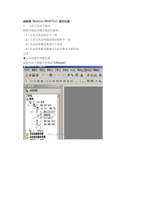
施耐德Modicon M340 PLC 通讯问题1、主站与从站不通讯能够导致此问题出现的可能是:(1)主站与从站地址不一致(2)主站与从站传输速度波特率不一致(3)从站的参数设置调节不完善(4)从站的参数设置调节后没有断电从新启动方法:◆主站波特率参数设置鼠标双击下图箭头所指的“CANopen”上面两步完成主站波特率参数设置◆从站波特率参数设置与CANopen地址设定(1)变频器设定参照变频器说明书进行设定,设定完成后需要断电从新启动设定值才生效。
例:ATV 31H异步电机变频器主要参数设定(参照ATV 31H说明书)。
◆电机参数的设定---------------------说明书中第26页◆功能访问等级---------“L3”--------说明书中第46页◆配置给定1------------“CRn”-------说明书中第46页◆混合模式-------------“SIN”-------说明书中第48页◆电机缺相故障配置-----“NO” -------说明书中第89页◆CANopen:变频器地址---“”-----------说明书中第93页◆CANopen:传输速度------“”----------说明书中第93页注:◇“CANopen:变频器地址”值设定必须与从站硬件组态保持一致,如图(26)所示此时CANopen:变频器地址就应该设定为“2”◇“CANopen:传输速度”值设定必须与图(25)“传输速度”保持一致(2)CANopen模块设置见上图CANopen模块箭头所示,上面两个旋钮“Ten”“Zero”为地址设定,该岛在从站的地址小于10时“Ten”也必须调到“0”位置,否则即为地址错误设定不能通讯连接。
下面的“Autobaut”旋钮为波特率设定,其各档位对应的波特率依据该模块侧面的参数说明。
调节该模块各档位时一定要在断电模式下进行,否则设置是无效的。
2、电脑与PLC不通讯能够导致此问题出现的可能是:(1)通讯方式与“设置地址”不一致对应当前的通讯模式“MODBUS”或“USB”在上图的“设置地址”正确选择对应的地址模式。
RM4036通讯协议

"@01W7000007"表示第01号模块的所有通道清零,若成功模块应返回":0136"
注意:"+"号不是指令的一部分
4036的写指令只有清零功能,而不能设为非零初值
写指令返回数据格式
如果模块成功收到并正确解析写指令,返回":+站号+板号";否则无返回
模块名称
RM4036
模块功能
6路脉冲量计数模块
读指令格式
@+站号+R
读指令说明
@:是指令标识符
站号:也称作模块号或模块地址,从00-15。
一条485通讯线上最多可挂接16个rm模块。
注意不要把站号和通道号搞混,每个rm4036模块有6个通道
R:指明操作类型为“读操作”
举例:@00R、@01R、@15R
注意不要把站号和通道号搞混,每个rm4036模块有6个通道
W:指明操作类型为“写操作”
通道号:0-5(0至5通道)、7(代表所有通道),注意:通道号=6无意义
输出值:固定为"0000",其他写法无意义
校验码:通道号与输出值之和
举例:"@00W0000000"表示第00号模块的0通道清零,若成功模块应返回":0036"
2.正因为4036与4035极为相似,所以针对4036编写的程序可直接用于4035,因此在组态
软件中,如果没有4035的驱动,可用4036的驱动来替代
3.由于4036中用8254进行计数,向4036发送清零指令成功后,4036并不立刻清零,而是在下次脉冲到来时才清零,这是由8254的特性决定的。这种特性可能会给用户使用带来不便,所以更简单易行的办法是干脆不清零,而是在每次需要重新开始计数时,记下计数器的当前值,以后每次读数时都减去这个值,就得到实际的脉冲数。
RM4035、RM4036远端脉冲量采集模块使用指南
-1-RM4035、RM4036使用指南1.概述RM4035、RM4036远端脉冲量采集模块适用于各类工业现场,可输入6路脉冲信号,并通过RS485接口,与上位机进行实时通讯。
RM4035、RM4036选用AT89C51单片机和82C54、16位计数芯片,可输入5V ,12V ,24V 频率为1~10KHZ 脉冲信号,并通过RS485与上位机通讯。
它同时采用了光电隔离技术,使供电电源和通讯与脉冲输入分开,使模块的抗干扰能力进一步加强。
RM4035是测频模块,RM4036是计数模块。
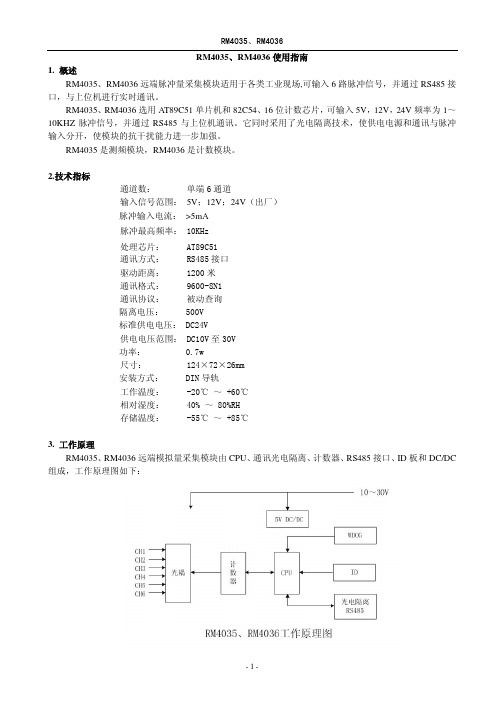
2.技术指标通道数:单端6通道输入信号范围:5V ;12V ;24V (出厂)脉冲输入电流:>5mA 脉冲最高频率:10KHz 处理芯片:AT89C51通讯方式:RS485接口驱动距离:1200米通讯格式:9600-8N1通讯协议:被动查询隔离电压:500V 标准供电电压:DC24V供电电压范围:DC10V 至30V 功率:0.7w尺寸:124×72×26mm 安装方式:DIN 导轨工作温度:-20℃~+60℃相对湿度:40%~80%RH 存储温度:-55℃~+85℃3.工作原理RM4035、RM4036远端模拟量采集模块由CPU 、通讯光电隔离、计数器、RS485接口、ID 板和DC/DC组成,工作原理图如下:-2-3.1CPURM4035、RM4036模块上的CPU 选用AT89C51,其速度快、内含2K ROM 、128byte RAM ,端口驱动能力达20mA ,能较好地适用于远端数据处理。
3.2RS485接口RM4035、RM4036选用MAX485ECPA 接口芯片完成RS485数据通讯。
MAX485ECPA 驱动达1200米,传输速率250Kb/S ,可连接32个站点,±15KV 的抗静电冲击,工作温度范围-40~+80℃。
3.3脉冲计数RM4035、RM4036选用82C54,提供16bit 的脉冲计数值。
Voltaire 4036 IB交换机介绍

Voltaire 4036高性能QDR InfiniBand导向器级交换机Voltaire公司是全球网格骨干解决方案的领导者,致力于为下一代数据中心网络化计算提供最为全面的解决方案。
Voltaire公司的产品涵盖了从服务器到网络交换到存储互联的各个领域,凭借先进的架构设计以及严谨的质量控制,Voltaire公司的软硬件产品在全球用户市场获得了广泛的好评,通过IBM、HP、SGI、NEC、SUN等合作伙伴建立了OEM合作关系,Voltaire公司的产品以及解决方案正在被部署在各行各业。
作为业高性能InfiniBand交换解决方案,Voltaire 4036为高性能计算集群和网格提供了水平空前的性能和扩展性。
4036交换机能使高性能应用运行在分布式的服务器、存储和网络资源上。
Voltaire 4036对单个机箱中的36个节点精心设计并提供了QDR规格的40Gb/s通讯带宽,多台4036或者与Voltaire其他产品配合,我们可以搭建更大规模的集群运算系统,可配置的节点数量范围从十几个到几千个,内部无阻塞的交换设计最大限度的为集群运算系统提供了可靠高效的通讯环境一、Voltaire 4036模块介绍Voltaire 4036主要由主机箱、sPSU电源模块以及相应的系统散热模块构成,整机采用模块化设计、无线缆接插件紧密连接结构,大大提高了设备的可靠性,同时方便了系统安装以及以后的维护工作。
4036机箱及相关部件Voltaire 4036机箱采用工业标准设计完全符合19英寸机柜的安装,支持网络机柜和服务器机柜安装使用;高度为1U,在一个标准42U机柜中可以轻松部署多台Voltaire 4036;Voltaire 4036提供了机架导轨,更方便机箱的机柜安装;1. 对外端口Voltaire 4036机箱提供了36个QDR 40Gb/s端口,总计可以提供2.88Tb/s吞吐量;2. 管理模块Voltaire 4036内置了子网管理器,无须在服务器上安装子网管理器软件;管理模块提供了标准的DB9串口以及以太网连接接口提供远程管理。
光纤差动保护原理介绍

差动保护特点
►装置采用了经差流开放的电压起动元件, 负荷侧装置能正常起动
►差动保护能自动适应系统运行方式的改变
►装置能实测电容电流,根据差动电流验证 线路容抗整定是否合理
差动保护特点
►装置能实时监测通道工作情况,当通道发 生故障或通道网络拓扑发生变化时,装置 能起动新的同步过程,直至两侧采样重新 同步,同时记录同步次数及通道误码总数 等;两侧采样没有同步时,差动保护自动 退出。
电容电流补偿条件
容抗整定和实际系统不相符合判据:
0且 .75*XUXc1Uc1IC0D或 .1I0N.或 75I*CIDCD0.1XIUNc1
其中Icd为正常情况下的实测差流,即实际的电容电流; 1.实测电容电流和经XC1计算得到的电容电流具有可比性(至少有一个>0.1In) ,并且较大的0.75倍>较小值,可认为容抗整定和实际系统不相符合。 2.当实测电容电流和经XC1计算得到的电容电流都小于0.1In时,认为两者不具备 可比性,不再判别容抗整定是否同实际系统相符。
光纤差动保护
►采样同步 ►数据交换/通信构成
▪ 通道方案 ▪ 码型变换 ▪ 时钟提取 ▪ 通道监视
►保护原理 ►2M与64K接口的区别
通道方案
一 专用光纤 二 复接PCM
专用光纤
►一根光纤只用来传输一个方向的保护信息, 不与其它任何信息复用。
►一对光纤可用来传输(双向)一条线路两 侧的保护信息。
数据发送 64Kb/s 从SCC来
发时钟
数据接收 64Kb/s 去SCC
通信接口的功能框图
码型变换
光纤发送 (主)
光纤
时钟提取 DPLL
电信网络安全解决方案
长沙电信网络安全解决方案湖南计算机股份有限公司网络通信及安全事业部目录一、长沙电信网络安全现状由于长沙电信信息网上的网络体系越来越复杂,应用系统越来越多,网络规模不断扩大,逐渐由Intranet扩展到Internet。
内部网络通过ADSL、ISDN、以太网等直接与外部网络相连,对整个生产网络安全构成了巨大的威胁。
具体分析,对长沙电信网络安全构成威胁的主要因素有:1) 应用及管理、系统平台复杂,管理困难,存在大量的安全隐患。
2) 内部网络和外部网络之间的连接为直接连接,外部用户不但可以访问对外服务的服务器,同时也很容易访问内部的网络服务器,这样,由于内部和外部没有隔离措施,内部系统极为容易遭到攻击。
3) 来自外部及内部网的病毒的破坏,来自Internet的Web浏览可能存在的恶意Java/ActiveX控件。
病毒发作情况难以得到监控,存在大范围系统瘫痪风险。
4) 缺乏有效的手段监视、评估网络系统和操作系统的安全性。
目前流行的许多操作系统均存在网络安全漏洞,如UNIX服务器,NT服务器及Windows桌面PC。
管理成本极高,降低了工作效率。
5) 缺乏一套完整的管理和安全策略、政策,相当多的用户安全意识匮乏。
6) 与竞争对手共享资源(如联通),潜在安全风险极高。
7) 上网资源管理、客户端工作用机使用管理混乱,存在多点高危安全隐患。
8) 计算机环境的缺陷可能引发安全问题;公司中心主机房环境的消防安全检测设施,长时间未经确认其可用性,存在一定隐患。
9) 各重要计算机系统及数据的常规备份恢复方案,目前都处于人工管理阶段,缺乏必要的自动备份支持设备。
10)目前电信分公司没有明确的异地容灾方案,如出现灾难性的系统损坏,完全没有恢复的可能性。
11) 远程拔号访问缺少必要的安全认证机制,存在安全性问题。
二、长沙电信网络安全需求分析网络安全设计是一个综合的系统工程,其复杂性丝毫不亚于设计一个庞大的应用系统。
长沙电信信息网的安全设计,需要考虑涉及到承载的所有软硬件产品及处理环节,而总体安全往往取决于所有环节中的最薄弱环节,如果有一个环节出了问题,总体安全就得不到保障;具体就以下几个方面来分析。
- 1、下载文档前请自行甄别文档内容的完整性,平台不提供额外的编辑、内容补充、找答案等附加服务。
- 2、"仅部分预览"的文档,不可在线预览部分如存在完整性等问题,可反馈申请退款(可完整预览的文档不适用该条件!)。
- 3、如文档侵犯您的权益,请联系客服反馈,我们会尽快为您处理(人工客服工作时间:9:00-18:30)。
W:指明操作类型为“写操作”
通道号:0-5(0至5通道)、7(代表所有通道),注意:通道号=6无意义
输出值:固定为"0000",其他写法无意义
校验码:通道号与输出值之和
举例:"@00W0000000"表示第00号模块的0通道清零,若成功模块应返回":0036"
注意:"+"号不是指令的一部分
读指令返回数据格式
1--1字节:帧头(或称前导符),固定为冒号":"
2--5字节:通道1数据
……
22--25字节:通道6数据
26--33字节:全部是"0"(用来占位)
34--35字节:当前站号,例如"00"、"01"、"15"等
36--37字节:板号固定为"36",代表4035或4036
用户把每个通道的数据(4字节的字符串)解析出来后,这个字符串已经是一个十进制串,转化为数字类型即可,得到的数值应该在0-9999之间
写指令格式
或称清零指令,格式为:@+站号+W+通道号+输出值+校验码
写指令格式说明
@:是指令标识符
站号:也称作模块号或模块地址,从00-15。
一条485通讯线上最多可挂接16个rm模块。
"@00W5000005"表示第00号模块的5通道清零,若成功模块应返回":0036"
"@01W7000007"表示第01号模块的所有通道清零,若成功模块应返回":0136"
注意:"+"号不是指令的一部分
4036的写指令只有清零功能,而不能设为非零初值
写指令返回数据格式
如果模块成功收到并正确解析写指令,返回":+站号+板号";否则无返回
写指令返回数据格式说明
帧头:或称前导符,固定为冒号":"
站号:成功收到写指令的模块的站号,从00-15。
板号:固定为"36",代表4035或4036
帧尾:固定为换行回车0x0A,0x0D。注意:不是0x0D,0x0A
使用提示
1.4036与4035极为相似,4036为计数模块,4035为测频模块,定货时应特别注意
38--39字节:帧尾,固定为换行回车0x0A,0x0D。注意:不是0x0D,0x0A
读指令返回数据格式说明
返回数据共39个字节,39 = 1 + 4 * 6 + 8个"0" + 4字节(站号板号) + 2字节(换行回车)
rm4036共6个通道,每个通道占4个字节,注意第1个字节为前导符,从第2个字节开始才是通道数据
2.正因为4036与4035极为相似,所以针对4036编写的程序可直接用于4035,因此在组态
软件中,如果没有4035的驱动,可用4036的驱动来替代
3.由于4036中用8254进行计数,向4036发送清零指令成功后,4036并不立刻清零,而是在下次脉冲到来时才清零,这是由8254的特性决定的。这种特性可能会给用户使用带来不便,所以更简单易行的办法是干脆不清零,而是在每次需要重新开始计数时,记下计数器的当前值,以后每次读数时都减去这个值,就得到实际的脉冲数。
"@00W1000001"表示第00号模块的1通道清零,若成功模块应返回":0036"
"@00W2000002"表示第00号模块的2通道清零,若成功模块应返回":0036"
"@00W3000003"表示第00号模块的3通道清零,若成功模块应返回":0036"
"@00W4000004"表示第00号模块的4通道清零,若成功模块应返回":0036"
模块名称
RM4036
模块功能
6路脉冲量计数模块
读指令格式
@+站号+R
读指令说明
@:是指令标识符
站号:也称作模块号或模块地址,从00-15。
一条485通讯线上最多可挂接16个rm模块。
注意不要把站号和通道号搞混,每个rm4036模块有6个通道
R:指明操作类型为“读操作”
举例:@00R、@01R、@15R
