史密斯5000tpd燃烧器介绍
燃烧机工作原理
燃烧机工作原理燃烧机是一种用于产生火焰和热能的设备,常见于工业生产和能源领域。
它通过将燃料与空气混合并点燃,产生高温高压的燃烧气体,从而产生动力或者加热效果。
下面将详细介绍燃烧机的工作原理。
一、燃烧机的基本组成1. 燃料供应系统:燃烧机通过燃料供应系统将燃料输送到燃烧室。
这个系统通常包括燃料泵、燃料过滤器、燃料调节器等组件。
2. 空气供应系统:燃烧机需要将空气与燃料混合才干进行燃烧。
空气供应系统包括风机、进气管道、空气过滤器等。
3. 点火系统:点火系统用于点燃燃料和空气混合物,产生火焰。
常见的点火系统有火花塞、电火花点火器等。
4. 燃烧室:燃烧室是燃烧机内部的空间,用于容纳燃料和空气混合物进行燃烧。
燃烧室的结构和形状会影响燃烧效率和火焰稳定性。
5. 控制系统:控制系统用于监测和控制燃烧机的工作状态,包括燃料和空气的供应量、点火时机等。
控制系统通常由传感器、控制器和执行器组成。
二、燃烧机的工作过程1. 燃料供应:燃烧机通过燃料供应系统将燃料输送到燃烧室。
燃料可以是液体燃料、气体燃料或者固体燃料。
2. 空气供应:空气供应系统将空气吸入燃烧机,并与燃料混合。
空气中的氧气是燃烧的必要条件,它与燃料混合后形成可燃混合物。
3. 点火:点火系统通过产生火花或者其他点火方式将燃料和空气混合物点燃,引起燃烧反应。
点火时机的控制对于燃烧效率和火焰稳定性至关重要。
4. 燃烧:一旦点燃,燃料和空气混合物开始燃烧。
在燃烧过程中,燃料中的化学能被释放为热能,产生高温高压的燃烧气体。
5. 热能利用:燃烧产生的热能可以用于多种用途,例如加热水、蒸汽发生、动力输出等。
燃烧机的设计和控制可以最大限度地提高热能利用效率。
三、燃烧机的分类根据燃料类型和燃烧方式的不同,燃烧机可以分为多种类型,包括以下几种常见的燃烧机:1. 煤气燃烧机:使用天然气或者液化石油气等煤气作为燃料,常见于家庭和工业热源供应。
2. 油燃烧机:使用重油、柴油等液体燃料进行燃烧,广泛应用于发电、工业加热等领域。
Eaton CF5000, MF5000 and FXP5000 火警面板安装和用户手册说明书

Installation and user manual for theCF5000, MF5000 and FXP5000 range of fire panels 16 zone panelsImportant InstructionsInstallation and user Manual for the CF5000, MF5000 and FXP5000 range of fire panels February 2015 2ContentsPANEL INSTALLATION..........................................................................................................................................................3Installation................................................................................................................................................................................3PANEL WIRING......................................................................................................................................................................3Mains power supply................................................................................................................................................................3Recommended Wiring Types..................................................................................................................................................3Fuse Ratings............................................................................................................................................................................3Battery connection..................................................................................................................................................................3Zone Wiring (5)Sounder Wiring........................................................................................................................................................................5WIRING CONNECTION DRAWING.......................................................................................................................................5Wiring Connection Drawing 16 Zone........................................................................................................................................ 5Fault Fire Relay........................................................................................................................................................................5Class Change...........................................................................................................................................................................5Repeater Panel........................................................................................................................................................................6Auxiliary Relays........................................................................................................................................................................6Interlink Panels........................................................................................................................................................................7Installation Check....................................................................................................................................................................7Zone Circuits............................................................................................................................................................................7Sounder Circuits......................................................................................................................................................................7COMMISSIONING THE SYSTEM.........................................................................................................................................8USER INFORMATION............................................................................................................................................................9 Mute buzzer ............................................................................................................................................................................9Silence alarm...........................................................................................................................................................................9Reset after alarm activation.....................................................................................................................................................9Reset without a fire activation.................................................................................................................................................9Evacuate..................................................................................................................................................................................10Enable sounders......................................................................................................................................................................10Disable sounders.....................................................................................................................................................................10Disable a zone Enable a zone..................................................................................................................................................10MAINTENANCE......................................................................................................................................................................11 User Inspections and Tests.....................................................................................................................................................11One man walk test (by engineer)............................................................................................................................................12Individual zone test facility.......................................................................................................................................................12Latch on fault facility................................................................................................................................................................13 PANEL PROGRAMMING OPTIONS......................................................................................................................................14 Non latching zones.................................................................................................................................................................. 14TABLES...................................................................................................................................................................................15Sounder and Visual Indication..................................................................................................................................................15Technical Specification. (16)Panel Wiring Mains Power SupplyThe mains supply should be exclusive to the fire alarm as detailed in BS5839 part 1 or applicable local standard. It is recommended that a double pole fused spur unit is used and marked “FIRE ALARM DO NOT SWITCH OFF ”, this should be for the sole use of the fire alarm. Within the panel, the mains supply should be isolated from the zone and alarm line wiring and should be connected to the terminal block marked MAINS .Recommended Wiring TypesThe following cable type and size are recommended:Mains wiring 1.5mm 2, 2 core, fireproof cable Zone wiring 1.5mm 2, 2 core, fireproof cable Sounder wiring1.5 to2.5mm 2, 2 core, fireproof cableFire/Fault Output Wiring 0.5mm 2, 2 core, fireproof cable WARNINGDO NOT USE AHIGH VOLTAGE TESTERWHEN WIRING IS CONNECTED TO ANY ELECTRONIC EQUIPMENTFuse RatingsMains Fuse Battery Fuse Sounder Circuits 1.6A AT Anti Surge 6.3A AT Anti Surge 500mA PolySwitch deviceImportant Instructions3Installation and user Manual for the CF5000, MF5000 and FXP5000 range of fire panelsFebruary 2015 Mount the panel, using pre drilled screw positions, to the wall. This will prevent any possible brick dust contamination of the panel internal circuitry. Use Three No.10 x 1 ¼” (5.0 x 30mm approx.) pan head screws. When using 20mm conduit entry direct to ensure a wide distribution of pressure whentightening the coupling.Panel InstallationPlease read the following instructions before installing and wiring the fire alarm panel.These ranges of panels are EN54 parts 2 and 4 certified and have been designed to comply with BS5839 part 1:2002 installations. The panels have two optional features: •FIRE ALARM DEVICES: (EN54 part 2 clause 7.8)•TEST CONDITION: (EN54 part 2 clause 10.0)In common with all electrical equipment the panel should be installed in a clean, dry, well-ventilated area, not in direct sun light and avoiding cold areas where possible. Note that temperatures in excess of 40°C and below -5°C will affect the panel operation. The panel should be located away from any potential hazard, in a position where it is readily accessible to authorised staff and the fire services. Ideally on the perimeter of a building near a permanent entrance.Battery connectionThe 16 zone panel requires two YUCEL 12V 4Ah Batteries (supplied).Connect the red battery wire to the red battery terminal (+)of battery one.Connect the black battery wire to the black battery terminal (-) of battery two. Then connect the link cable as shown here.Battery Installation1.Ensure that the panel is disconnected from mains power.Carefully remove the ribbon cable from the main board.Note: Do not attempt to remove the cable from the display board connector.2.Attach battery cables to battery as shown in illustration above “Battery connection”.Note: Do not attach battery cables to main PCB before completing the next stage.4.Connect the mains cable and power up the panel.Once powered up attach the battery cable to the main panel PCB following the illustration above “Battery connection”.3.Carefully reattach the ribbon cable.The 16 Zone panels have a battery bracket to secure the batteries this should be fitted before reattaching the ribbon cable.Important InstructionsInstallation and user Manual for the CF5000, MF5000 and FXP5000 range of fire panels February 2015 4Zone wiringEach zone circuit is supplied with an End of Line Monitor unit (EOLM-1). All zone circuits must be terminated with an EOLM-1, taking care to observe the correct polarity.Sounder wiringThe fire alarm control panel has four separately protected,line monitored, sounder circuits for use with polarised and suppressed bells, sounders, strobes, relays etc.The wiring for each sounder circuit is to be a parallel circuit with the 6K8, end of line resistor (EOLR), fitted at the end of the installed sounder circuit wiring. No ‘spurs’ nor ‘tee’s’ are permitted.Wiring Connection DrawingOn-board Fault/Fire relayEach panel has one Fire and Fault relay fitted.The Fault relay provides a fused volt free set of change over contacts. These contacts are not monitored.The relay has been designed to be ‘fail safe’, so that in the event of a total power loss, the relay contacts will be active.The Fire relay provides a fused volt free set of change over contacts. These contacts are not monitored.The relays are fused with a PolySwitch device rated at 500mA / 60V DC.Class changeThe sounder circuits can be operated by an external volt free contact (Relay, Switch, Timer etc.). A short circuit at this terminal will activate the sounder circuit outputs (non-latching), removal of the short circuit will de-activate the sounder circuit output.It should be noted that activation of the class change input will give no visual indication on the panel and will not operate the auxiliary relays.Important Instructions5Installation and user Manual for the CF5000, MF5000 and FXP5000 range of fire panels February 2015 Repeater panelThe panel has a RS485 repeater output as standard. The repeater panel has been designed to provide a cost effective installation solution, requiring only two interconnecting wires from the master panel. Several repeater panels can be installed from the master panel by ‘cascading’ each repeater panel; again only two interconnecting wires are required between each repeater panel.As each repeater has its own mains supply and standby battery, the main panel standby time is not affected by the number of repeater panels installed. The repeater panel is suitable for up to 16 zones and displays all the same indications as the main panel, but with the addition of an indicator test and mute buzzer facility.WiringConnect the repeater, RS485 TX+ and TX- terminals of the main panel, to the repeater panel positive and negative input terminals. Main Panel Repeater Panel TX+ to +ve input terminal TX-to-ve input terminalAuxiliary RelaysThe Auxiliary (“Zonal”) relays provide additional external fire indications per zone, for example AUX 1 will activate when there is a fire condition on Zone 1 and will deactivate when the fire condition is cleared.The polarity of the auxiliary relay can be changed to either Normally Open or Normally Closed via the associated jumper on the auxiliary relay board.Important InstructionsInstallation and user Manual for the CF5000, MF5000 and FXP5000 range of fire panels February 2015 6Normally Open = Jumper across 1&2Normally Closed = Jumper across 2&3Interlinking PanelsTwo panels can be linked together as illustrated below.Zone 1 of Panel 1 must be connected to AUX 1 of Panel 2,with and EOLM-1 and 680Ω resistor as shown in the diagram above.Zone 1 of Panel 2 must be connected to AUX 1 of Panel 1,with and EOLM-1 and 680Ω resistor as shown in the diagram above.Zone 1 on both panels must be configured to Non-latching mode. This changes the operation of AUX 1 so that it triggers on any zone fire condition excluding zone 1.When Panel 1 detects a fire on zones 2-8/16, AUX 1 will activate placing the 680ohm resistor across Zone 1 of Panel 2.This will cause Panel 2 to go into fire but will not activate its AUX 1 output.Likewise, when Panel 2 detects a fire on zones 2-8/16, AUX 1 will activate placing the 680ohm resistor across Zone 1 of Panel 1. This will cause Panel 1 to go into fire but will not activate its AUX 1 output.Installation CheckWith the EOLM-1’s and EOL resistors fitted in the main panel, connect the mains supply and battery. Check the green power on LED is lit and that no other indicators are lit.Check that the panel operates correctly by entering the access code (3112), followed by silence, followed by reset,check all indicators light up momentarily. Check each zone and alarm line for open and short circuit fault monitoring.Zone circuitsDisconnect the mains and battery supply, wire in the zone circuits, one at a time, with the EOLM-1 transferred to the end of the zone (check polarity) but with no detectors fitted.Power up the panel by connecting the mains supply and battery. Check that the last call point in each zone operates correctly by using the supplied call point test key. Reset the panel after each activation. Fit all the detectors (a zone at a time) and check that the panel shows a healthy state. If there is a problem (zone fault showing) check the faulty circuit for continuity, correct polarity and polarity of the base diodes.(DO NOT USE A HIGH VOLTAGE INSULATION TESTER).Sounder circuitsDisconnect the mains and battery supply. Wire in the sounder circuits, one at a time, transferring the end of line resistor to the end sounder/bell on each circuit. Power up the panel as before and verify that no fault shows. If there is a fault indication, check the affected circuit for short circuit,continuity and polarity.(DO NOT USE A HIGH VOLTAGE INSULATION TESTER).Important Instructions7Installation and user Manual for the CF5000, MF5000 and FXP5000 range of fire panelsFebruary 2015 Important InstructionsInstallation and user Manual for the CF5000, MF5000 and FXP5000 range of fire panels February 2015 8Commissioning the systemAssuming that the installation instructions and installation checks have been carried out successfully, the fire alarm system is ready for commissioning.Each detector and call point should be tested in turn to ensure that it operates, indicates the correct zone fire LED and operates the alarm output correctly, ensuring all sounders/bells operate.Walk test facilityA walk test function has been included in this range of panels to enable one person (electrical contractor or installer) to test the fire detection system without an assistant. This function is for the sole use of the electrical contractor or installer and not for normal operational use.The walk test facility access code is located inside the fire detection control panel.Once the walk test code has been correctly entered the ‘test in progress’ indicator will show and the buzzer will pulse, this sets a time window of 10 minutes.If a detector or call point is triggered within this period the sounders will operate for a short time then the system will automatically reset ready for the next call point or detector activation.If a detector or call point is not operated within the 10 minute period then the system will automatically reset and return to normal operation.The walk test facility can be terminated at any time during test by pressing the ‘reset’ button.Important Instructions9Installation and user Manual for the CF5000, MF5000 and FXP5000 range of fire panels February 2015 User InformationThere are 2 access codes used by the control panel:•Access level 2 - client code (3112)•Access level 3 - engineers codeThese codes are displayed on the rear of the front panel. The access level 2 code is also shown on the panel key fob.Level 2 access permits the following functions:- Silence alarm - Evacuate- Enable and disable zones - Enable or disable sounders - System resetThe access code (level 2 or 3) is enabled by pressing the six control panel front buttons in the correct sequence.An audible signal indicates that the access code keyed in is correct.Mute buzzerSilences control panel’s internal buzzer Access code level 2 +1234556Reset after fire alarm activationSilences buzzer, resets the panel indicators, resets detectorsand resets control relays Access code level 2 +2Reset without a fire activation(e.g. to reset a fault indication when zone fault latch facility)Silences buzzer, resets the panel indicators, resets fault relayAccess code level 2 + +12Silence alarmSilences buzzer, resets the panel indicators, resets detectors and resets control relaysAccess code level 2 + +15The yellow LED of the zone 1 will light up and the internalbuzzer will pulse rapidly, push button �several times until both the required zone and disabled yellow LED’s are lit.Push button to disable the indicated zone. Repeat this procedure to disable further zones.Internal buzzer will rapidly pulse. Push button �several times until sounder LED turns off.Push button to confirm enable soundersThe yellow LED of the zone 1 will light and the internal buzzer will pulse rapidly, push button �several times until both the disabled and sounders disabled yellow LED’s are lit.Push buttonto disable sounders.Important InstructionsInstallation and user Manual for the CF5000, MF5000 and FXP5000 range of fire panels February 2015 10EvacuateOperates the control panel’s sounder circuits and fire relay(s)Access code level 2 +3Enable SoundersEnable Sounders 2 +4Operates the control panel’s sounder circuits and fire relay(s)Access code level 2 +The internal buzzer will pulse at a slow rate and the disabled and sounders disabled LED’s will remain lit.To silence the internal buzzer Access code level 2 +115Disable SoundersIsolates sounder circuits from the system Access code level 2 +Disable a zoneIsolates required detection zone from the systemAccess code level 2 + �4141The internal buzzer will pulse at a slow rate and the disabledand zone disabled LED’s will remain lit.To silence the internal buzzerAccess code level 2 + �5Maintenance GeneralIt is vital that the fire alarm system is checked for correct operation as per the requirements of BS5839 or applicable local standard.Daily inspection (by user)The panel should be visually inspected daily to ensure that the green ‘power on’ indicator is lit and that no fault indication is showing.Notify any fault indication to your maintenance company.Weekly Test (by user)Visually inspect panel as per daily inspection.Test panel indicators:Access code level 2 +All indicators will light up and the panel internal buzzer will sound.The test in progress LED will light up, the panel is now in a ‘one- shot’ auto reset mode. The call point can now be activated using the test key, the sounders will operate for a short period (3 seconds) after which the panel will automatically reset and return to normal operation. If a call point or detector is not operated within a short period, the panel reverts to normal operation and the test is abandoned.It is advised that a different call point is tested each week to ensure that all call points are tested in rotation.Log test results in log book.The yellow LED of the zone 1 is flashing. Push button �several times until the yellow led of the relevant zone is flashing.Push button to enable the indicated zone.Repeat this procedure to enable further disabled zones.Enable ZoneOperates the control panel’s sounder circuits and fire relay(s)Access code level 2 +4416Inspection and servicing(by service provider) Quarterly TestCheck log book entries since last visit and verify that remedial action has been taken (if required). Visually inspect panel as per daily inspection. Carry out weekly test. Visually inspect battery and battery connections. Carry out battery load test by disconnecting the mains supply and check that the battery is capable of supplying the alarm sounder load by activating a call point. Log test results in log book.Bi-yearly TestAs per quarterly test.Visual inspection of site to check for compliance of system to recommendations of local standard.All controls and indicators of control panel need to be checked for correct operation.All external circuits should be tested for correct fault monitoring.Log test results in log book.Annual TestAs per by-yearly testAlso all call points on the system should be tested and the automatic fire detectors should be visually inspected to ensure they have not been damaged or painted over. The automatic detectors should then be test- operated.Log test results in log book.Every 5 yearsReplace sealed lead acid battery every 5 years (recommended).It is advised that a different call point is tested each week to ensure that all call points are tested in rotation.Log test results in log book.Repeat the process for all zones.Once finished useAccess code level 3 +Toggle to the zone in test- use button to cancel the zonetest.If another zone sees a fire event then the panel will over-ride the individual zone test and go into full fire.1Maintenance Engineers code facilitiesThe engineering access code label can be found in the panel back box (internal).One man walk test facilityAccess code level 3 +Individual zone test facilityThis enables the engineer to test a relevant zone while the other zones can still be activated upon a fire event.Access code level 3 +Latch on zone fault facilityThis does not meet the requirements of EN54-2All zone faults will latch on the panel Access code level 3 +The test in progress LED will light up, the yellow LED of zone 1 will light up and the internal buzzer will pulse rapidly: push button several times until the required zone is selected.Push button to confirm the indicated zone.The internal buzzer will pulse at a slow rate and the corresponding zone LED’s will remain lit.The call point can now be activated using the test key, the sounders will operate for a short period (3 seconds) after which the panel will automatically return to test mode operation. If a call point or detector is not operated within a short period the panel reverts to normal operation and the test is abandoned.Test in progress LED will light up. Panel will now ‘latch until reset’ on all faults.The latch on fault facility can be terminated at any time by pressing the ‘reset’ button.633134Panel Programing OptionsSwitch setting facilityThe dip switches installed on the PCB allow certainprogramming options to be selected by the installationengineer.•Optional zone monitoring•Non latching zones•Sounder configuration (see diagram)NoteThese DIP switches are only read at power-up and notafter a reset.Please note the white blocks represent the switchpositionOptional Sounder ConfigurationThe sounder circuits can be programmed to have acontinuous or pulsed tone.The alarm panel must be programmed, via switch 4 of theDIP switch SW19 for the sounder settings required.Non latching zonesEach zone circuit can be configured to be latched orunlatched. This can be done by setting the switches on DIPswitches SW20 (Zones 1-4) and SW21 (Zones 5-8) asillustrated below.Zones 1 - 4Zones 5 - 8LED Flashing Internal Buzzer Intermittent LED IlluminatedInternal Buzzer SteadyPanel Fire/Fault IndicatorsS i t u a t i o nIndicationTechnical SpecificationPower SupplyMains Voltage230VA +10% -15% Nominal Current70mAMaximum Current200mAInput Fuse 1.6A AT Anti Surge Ripple Voltages24V 500mV24V Raw - 600mV5V O/P 100mV Output Voltages24V 24V +/-5%24V Raw - 24V +/-5%5V O/P 5V +/-5% Maximum Load Imaxb24V 650mV24V Raw - 2000mA5V O/P 300mA Standby Current Imaxa24V 100mA24V Raw - 80mAImin24V 25mA24V Raw - 25mA5V 20mA BatteriesNumber of Batteries2Part Number (Manufacturer)Yucell Y4-12 (Yuasa)Capacity4AhBattery Fuse 6.3A AT Anti SurgeMax Battery Charge Current500mAStand By Current220mAFloat Voltage27.1VBattery Switching Off Threshold19.98V (22.4V)+/- 200mV (Reinstatement Voltage)Battery Internal Resistance 1 OhmsInputsPanel Type16 ZoneDetection Zones16Detectors per Zone30OutputsAlarm Lines4Sounder Circuit Maximum Alarm Line Load400mA per Alarm LineSounder Circuit Minimum Alarm Line Load15mA per Alarm LineFire/Fault Relay Yes 500mA Maximum Current24V External power supply output Yes 300mA Maximum CurrentZonal Inputs Load Quiescent 3.5mAFire Indication Load35mA。
美国史密斯公司全系列产品
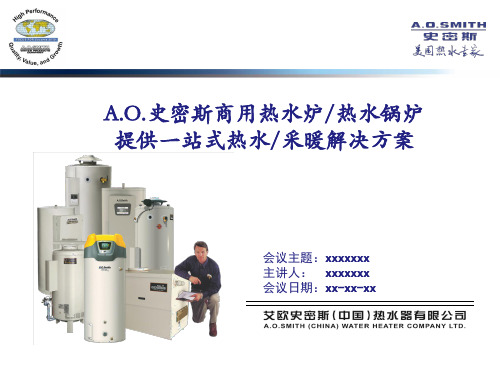
容积:307/379/322L 功率:41-99 kW
适用于酒店、工厂、健身娱乐、企事业等商业场所
商用容积式冷凝燃气热水炉
BTH 2009年Frost & Sullivan创新产品年度大奖
• • • • • • • •
容积:379/492L 功率:58/73/99 kW
全新的冷凝式设计,效率高达103% 螺旋形热交换器设计,热交换更彻底 特有的商用级金圭特护内胆,提供全方面保护 智能控制系统,实时监控运行状况,内置故障诊断 电子阳极保护,提供内胆更持久的保护 全预混的旋风式燃烧方式,燃烧更加高效 多种进风、排烟方式可选,PVC可用,适应性强 环保:CO、Nox排放量低于中国和美国标准
整体式户外型设计 制热量:3.5 kW 电功率:6-12 kW 整体式户外型设计 制热量:8k 电功率:6-12 kW
直热式空气能热泵热水机组 CAHP-HI
单机省 系统更省 COP值达4.3 制热量:40 kW
轻型商用容积式电热水炉
DEN
• 金圭特护内胆,优质INCLOY合金加热棒、超长阳极棒, 有效防腐抗垢,优质耐用 • 温控、高温极限、温度压力安全阀三重保护,安全可靠 • 加厚聚氨酯发泡保温层,减少热量损失 • 可采用点对点直接供热方式,节省能源 • 220V或380V电压可选,根据用户电功率配置 • 按美国承压标准2MPa设计,比家用电热水器高67%,高承压 • 体积小巧,占地面积小,安装、维护更容易
功率:657 kW
适用于商住楼、工厂、企事业、学校等商业场所
轻型商用热泵电热水器
CAHP-80/120
• COP高达3.5,高效节能,省电60%以上 • 室外型设计,避免噪音和冷风干扰,节省空间并创造 舒适家居环境 • 300/455L大容量承压式水箱,恒温出水 • 商用级金圭内胆,防腐抗垢,延长水箱使用寿命 • 热泵热水器专用压缩机,热水供应更稳定 • R134a制冷剂,绿色环保 • 整体式设计,安装简单,即插即用 • 外绕D型铜盘管,换热充分;双重隔离制冷剂,使用安全 • 超大LCD显示屏,全自动智能运行
史密斯燃气热水器原理
史密斯燃气热水器原理
史密斯燃气热水器是一种常见的热水供应设备,其工作原理是利用燃气燃烧产生的热能来加热水。
下面我们来详细介绍一下史密斯燃气热水器的工作原理。
史密斯燃气热水器的核心部件是燃烧器和热交换器。
首先,使用外部的水源将水输送到热水器内部的水箱中。
接下来,当用户需要热水时,启动燃气系统,将燃气输送到燃烧器中。
燃气在燃烧器中与空气混合,并被点燃产生火焰。
燃气燃烧产生的火焰会直接加热热交换器。
热交换器是一个金属管道系统,具有较大的表面积,可以更高效地传导热量。
当燃气燃烧产生的热量传导到热交换器时,交换器的金属管道会迅速吸热,并将热量传递给通过管道外壁流过的水。
通过热交换的过程,水的温度逐渐升高。
当水温达到设定的加热温度时,燃气系统会自动停止供气,燃烧器熄灭,从而停止燃气的燃烧。
升温过程完成后,热水就可以通过出水管道供应给用户使用。
为了保证燃气热水器的安全使用,史密斯燃气热水器还配备了多重安全保护系统。
例如,当燃气燃烧出现异常或热交换器温度过高时,热水器会自动切断燃气供应,同时还会配备过压保护、过流保护、漏电保护等功能。
总的来说,史密斯燃气热水器的工作原理是利用燃烧产生的热能来加热水,通过热交换器将热量传导给水,最终提供热水供
应给用户。
同时,热水器还配备多种安全保护系统,确保使用过程的安全可靠。
燃烧器说明书(中英文)

二级点火 Two Classes Ignition
角执行机构 Angle Action Device
400Nm,220V,4~20mA 控制电流 Control Current
四、安装与调试 Installation and Regulation 1、燃烧器安装 燃烧器上安装法兰与炉墙上预留的安装法兰用 12 只 M16×50
After regulation, close the box tightly, and protect it from dust.
五、操作步骤 Operation Steps 1、点火 Ignition (1)点火:检查油管路系统,将各手动阀置于开位。启动电动推进器按钮,将
点火枪送至油枪前端。将风油联动系统开度至 40%处,启动高能点火器点火按钮使其 点 火 , 接 着 打 开 燃 烧 器 前 的 点 火 油 枪 进 油 电 动 阀 , 此 时 燃 油 即 开 始 雾 化 燃 烧 。( 高 能 点火装置连续工作时间不能超过 30 秒),火焰稳定后火检着火信号反馈,主油枪进油 电动阀和回油电动阀打开,主油枪燃油雾化燃烧,点火油枪进油阀关闭,火检信号反 馈稳定,点火成功!(油枪前压力保证 2.8~3.5MPa)。 Ignition: check oil pipeline, and open all the manual valves. Press electric actuator start button, and advance spark rod to oil gun front. Open the air and oil regulator to 40%. Press HEA exciter ignition button, and open the oil inlet electric valve of ignition oil gun in front of burner, then the fuel is atomized combusting (the HEA exciter may not work over 30s continuously). The flame on signal is sent from flame scanner when the combustion is stable. Open oil inlet electric valve and oil return electric valve of main oil gun. Oil in the main oil gun is atomized combusting. Close oil inlet valve of ignition oil gun. When signals from flame scanner indicate stable
燃烧器基础知识

燃烧器是一种机械装置,用于控制空气和燃料的混合物,以便在混合物燃烧时,火焰也能维持任务所需的时间。
燃烧是在燃料和氧化剂之间进行的高温放热氧化还原反应,以产生气态产物以及热能和光能。
本质上,燃烧器是用于维持燃烧反应以加热流体或进行吸热化学反应或将液体转化为蒸汽等的装置。
实验室中常用的灯头称为本生灯。
它只是一根连接到燃料供应的管子。
燃料本质上是气态的。
燃料供应的流量由阀门调节,通常是针阀。
当阀门打开时,气体流过管子。
离开管子的气体可以被点燃,一旦点燃,顶部就会出现火焰,因为气体开始燃烧。
气体只在管子的顶部燃烧,而不是在管子内部燃烧,因为只有在管子的顶部才有足够的氧气。
它是一种方便且简单的设备,用于实验室规模过程中的加热、灭菌和燃烧任务。
工业燃烧器本质上更大更复杂。
其中一些典型类型是:空气分级燃烧器所有燃料通过内部空气喷射器与一定量的空气混合,然后根据燃烧过程的需要,空气从外部空气喷射器分阶段供应。
蓄热式燃烧器他们使用一对一起运行的燃烧器,以提高系统的热效率。
来自一个燃烧器的废气用于加热即将在另一个燃烧器中燃烧的空气,反之亦然。
因此,它们以交替循环运行。
自蓄热式燃烧器该燃烧器安装了恢复功能。
废气通过加热装置被拉回,进入的空气被废气加热。
辐射管燃烧器所有以前的燃烧器都有燃料和空气混合物在负载(原材料)的情况下燃烧。
在辐射管燃烧器中,燃烧过程发生在管中,管作为分隔燃料空气混合物和负载的边界。
热量通过辐射传递给负载。
燃烧器管理系统(BMS)燃烧器管理系统是用于管理工业燃烧器的启动、运行和关闭以使其安全运行的系统。
它能够管理任何使用火焰的设备,如熔炉、锅炉等。
该系统管理火焰、点火器、燃烧器和执行器。
燃烧器管理系统主要执行以下功能:在某些允许的互锁首先完成之前阻止设备启动,如果不满足某些要求的条件,它也可以禁止启动;除非并直到令人满意的净化完成,否则它会阻止设备点火;当燃烧操作开始时,只有在满足某些安全联锁装置的情况下,它才会有条件地维持它;它可以检测不安全的操作条件,甚至可以防止这些条件;向控制室提供各部件的状态信息和数据记录。
燃烧器认识-入门-应用基本知识

燃烧器基本知识A-什么是燃烧器、B-燃烧器的选用、C-常用符号单位换算、D-型号代表解读、E-基本操作常识A 、什么是燃烧器 燃烧器的定义是将燃料的化学能转变为热能的燃烧设备燃烧器的基本结构原理一、燃烧器的工作六步骤:给电、风机启动、安全检测、点火、输送燃料、燃烧。
二、燃烧器主要组成部份:机身、风机马达、油泵/电磁阀组、点火变压器、程序控制器等组成。
三、燃烧器(英语名Burner):是使燃料和空气以一定方式喷出混合或混合喷出的燃烧装置统称。
四、广义上的燃烧器按应用领域分:工业、民用、特种(电站)。
五、根据燃料通常被分为:燃气、燃油、双燃料。
1.燃气又可分为--天然气、城市煤气、液化气等;2.燃油又可分为--轻油、重(渣)油等;3.双燃料又可分为--轻油/天然气、重油/天然气等。
六、根据使用地点分为:陆用,船用(需船级社认证)。
七、根据结构又可分为:一体式,分体式。
八、燃烧类型很多,按燃烧方法分类:1.扩散式燃烧器(燃烧所需的空气不预先与燃气混合);2.大气式燃烧器(燃烧所需的部分空气预先与燃气混合);3.完全预混式燃烧器(燃烧所需的全部空气预先与燃气充分混合);4.引射式燃烧器(空气被燃气射流吸人或燃气被空气射流吸入);5.自然供风燃烧器(靠炉膛中的负压将空气吸入组织燃烧);6.鼓风式燃烧器(用鼓风设备将空气送人炉内组织燃烧);7.纯燃气燃烧器(仅限于燃用燃气);8.燃气+燃油联合燃烧器(可同时或单独燃用燃气或燃油);9.燃气+煤粉联合燃烧器(可同时或单独燃用燃气或煤粉);10.低NOx 燃烧器(低氮氧化物排放)。
九、燃烧器的应用范围:凡是以液体和气体燃料为能源,直接利用其热能的设备或场合都可适用,如:热水炉、 蒸汽炉、工业炉、焚烧炉,筑路机械、直燃式空调机等等。
十、燃烧器的基本要求:运行安全、节约能源、保护环境。
十一、燃烧过程的三要素为:燃料、氧化剂和点火源(这里指的是工业燃烧为迅速氧化碳氢燃料而产生大量能 源用于工业加热的过程)。
燃烧器

燃烧器一、燃烧机的工作原理符合燃烧机工作条件时,鼓风机马达开始转动,带动同轴的风扇叶转动,因离心力的原理,空气被高速旋转的叶轮送出,因蜗壳式的风机原理,送出的空气被吹向燃烧机的前方出口,在混合室内和进入的燃料充分混合(燃料分为燃气和燃油)。
而风量的控制是由风门驱动器带动风门挡板来完成,有的燃烧机风量挡板安装在鼓风机的吸入口进行控制,有的燃烧机安装在鼓风机的吹出口设置风挡进行控制。
当采用气体燃料时,燃气经过控制阀进入混合室,与空气混合,利用控制阀的开度来控制燃气量的多少;当采用燃油为燃料时,燃料通过电磁阀、油管进入喷油嘴,由喷油嘴喷出雾化状的燃油,在混合室内与空气混合,被空气进一步吹散、雾化,再进入炉膛内燃烧。
油路系统中有节流阀或控制燃油的压力,来改变喷嘴的出油量,控制火焰的大小。
燃烧机无论是燃油还是燃气,在和空气充分混合后,送入炉膛内燃烧,都必须有点火系统,在燃烧器上装有升压变压器,当初级通入电源后,变压器次级产生高压(8000~14000V),通过高压电缆送到打火电极上,点火电极击穿空气进行放电,形成电弧,点燃送入混合好的燃料。
分为两种形式,一种是两根,当通电时两根点火棒之间放电;另一种是一根,通电时,点火棒对地放电。
燃烧器上装有空气压力继电器,它用来感受风机风量的大小。
当风量达不到预先设定的要求时,压力继电器断开电路,燃烧器上程控器显示故障,停止燃烧,保证安全运行。
压力继电器分为两种,一种是采用负压的方式,在风机的进风口处装有一根管,管接至负压空气继电器,利用鼓风机风速大,抽力形成负压,使负压继电器动作;另一种采用正压,安装在风机出风的方向,装有一根管,连接至正压空气压力继电器上,当风机鼓风时,有风进入正压空气继电器,形成一个压力,使继电器动作。
燃烧机上还装有火陷监视系统,俗称电眼,在点火前进行检测和在点火后进行火焰监控。
在应该检测到火焰时,若检测不到火焰,则燃烧机程控器显示障,并切断燃料供应系统,防止爆燃。
史密斯燃烧器

D uo flex 燃烧器燃油系统操作说明书史密斯机械工业(青岛)有限公司2003.1目录一.总体说明二.工作原理三.机器参数四.油路,气路控制原理图五.机器的安装六.机器的调试和运行七.故障分析及处理八.维护和保养九.附录1.机械装配图2.电气控制图一、总体说明:本说明书用于指导用户对Douflex型燃烧器燃油点火系统进行正常操作及日常维护,以确保该系统发挥其正常工作效用,如用户在使用过程中遇到其它特殊情况,请及时与史密斯公司联系解决.二、作原理:本系统为Duoflex燃烧器燃油点火装臵,由油泵站和供油盘两部分组成。
其中油泵站由泵、溢流阀、过滤器、压力表组成,向供油盘提供5-10kg/cm2的低压燃油。
供油盘采用特殊的管路设计,可对输出燃油及压缩空气进行适时控制,其管路根据现场实际情况合理布臵,使用地脚螺栓固定。
气,液接口分别与气,油源通过金属管法兰连接。
燃油介质在供油盘经压缩空气(5-6kg/cm2)作用,通过点火枪喷嘴呈雾状喷射出来,弥散的微小油滴当遇到明火时可迅速燃烧,从而起到点火和助燃作用。
三.Duoflex燃烧器供油系统主要技术参数和要求:五.机器的安装:1.机器到达工厂后,安装前应详细阅读本说明书。
2.使主油箱位于水平地面,调整水平后用地脚螺栓固定; 根据实际情况放臵供油盘,并用地脚螺栓安装、固定。
3.配臵合适的金属管连接液、气管路,油管法兰间应放臵耐油橡胶垫,气管法兰间应放臵密封垫(详细参阅油箱装配图)。
4.接通泵装臵电机电源。
六.机器的调试和运行:6.1 调试前准备:1.检查气源及油、气管路、点火枪喷嘴,确保无破裂、堵塞、扭曲变形等情况,检查油箱液位是否正常。
2.检查油、气管路中各标准元器件是否有生锈或明显损坏现象,检查油泵。
3.检查所有压力表开关均应处于开启状态,确认油箱及供油盘上所有手控阀门处于关闭状态。
4.每次启动螺杆泵时,应先沿指示方向用手旋转主动螺杆使泵内注入使用介质,以保证各摩擦副有足够的润滑。
史密斯热水器原理

史密斯热水器原理史密斯热水器是一种家用热水供应设备,它通过一系列的物理原理来实现热水的加热和供应。
史密斯热水器的工作原理主要包括水循环、燃烧和热交换三个环节。
首先,水循环是史密斯热水器的基本原理之一。
热水器中的水从自来水管道进入热水器水箱,在水箱内部增压,然后通过水泵被输送到热水供应器或热水龙头等用户用水设备。
当用户打开热水龙头时,冷水管中的冷水被自动感应到,热水器即开始加热,加热后的热水经过密封管道运输到用户设备,用户可自由地使用。
其次,燃烧是史密斯热水器的关键原理之一。
根据市电启动装置或电阻丝点火装置的信号,燃烧器点火并开始燃烧,以产生热能加热水箱中的水。
燃烧器的燃烧产生的高温烟气通过烟道烟囱排出。
史密斯热水器通常使用燃气或电能作为燃烧介质,燃气热水器利用燃气进行燃烧,而电热水器则通过电阻丝产生高温。
最后,热交换是史密斯热水器的工作原理之一。
燃烧产生的高温烟气通过烟道烟囱排出时,烟气与水箱内的水之间进行热交换。
烟气和水之间的热交换通过热交换器实现,热交换器通常由铜管或不锈钢管制成,热搬运介质可以是燃气火焰、燃烧器表面的烟气或电加热元件的产生的热能。
燃烧产生的高温烟气从烟道通过热交换器表面,将热能传递到水箱中的水,使水的温度升高。
在史密斯热水器的工作过程中,还有一些辅助元素帮助实现热水的加热和供应。
例如,史密斯热水器通常配备有温控器,温控器通过感应水箱内的水温,调控燃烧器的工作状态,使热水的温度保持在用户需要的范围内。
此外,史密斯热水器还通常具有安全阀等安全设备,以确保热水器的安全运行。
总结起来,史密斯热水器的工作原理涉及水循环、燃烧和热交换等环节。
通过这一系列的工作原理,史密斯热水器能够将自来水源加热至用户需要的温度,供应给用户进行热水使用。
这种利用物理原理实现的设备,为人们提供了方便、舒适的热水使用体验。
分段燃烧技术在燃气采暖热水炉上的应用
|分户供暖专栏| Household Gas Heating Column2017年8月42介绍智能分段燃烧技术在燃气采暖炉上应用的优点,阐述如何进行火排数量的分配以及电磁阀和燃气比例阀的逻辑控制,从而实现更好的恒温调节。
分段燃烧技术在燃气采暖热水炉上的应用艾欧史密斯(中国)热水器有限公司/朱高涛 徐赛锋由于我国用户环境复杂多样,不同季节冷水进水温度有很大差异,欧系燃气采暖热水炉产品在引入中国市场以后,出现很多用户抱怨生活热水出水温度波动、忽冷忽热的问题,特别是寒冷的冬季和炎热的夏季——夏季水太烫,冬季水不热。
这一现象主要是因为不同季节的进水温度差异很大,而采暖炉产品的功率范围不能适应宽域调节而导致。
燃气快速热水器上普遍使用的智能分段燃烧技术在恒温调节中起至关重要的作用,它可实现在进水流量和进水温度以及燃气压力有变化的情况下,通过快速精准的负荷调节保持用户所设定的出水温度恒定,真正实现舒适恒温热水。
针对中国用户环境开发产品,我们认为有必要在采暖炉产品上引入该技术,给客户带来更多价值。
1 分段燃烧的原理和优点燃气采暖热水炉的燃烧系统由气阀、分配器、燃烧器等主要零部件组成。
控制器根据负荷需求调节气阀比例阀电流的大小,从而改变进入分配器的燃气流量。
分配器通过喷嘴的引射作用将燃气和空气的混合气体引入燃烧器进行充分混合,最后在燃烧腔内进行燃烧。
理论上可以通过控制比例阀电流的大小来控制燃气流量多少,从而实现燃烧功率从小到大的连续变化,但是随着燃气流量逐渐减小,空燃比变大,火焰无法在火排上维持稳定燃烧,最终熄灭。
相反若燃气流量过大,则氧含量不足,无法充分燃烧,CO 排放增高,且同时火焰变高,甚至触及换热器,导致换热器积碳。
所以单个火排有一个燃烧负荷范围,一般控制在0.7kW~2.3kW 左右。
因此无分段阀大气式燃烧器的负荷比一般只能做到1:3。
分段燃烧技术是通过在分配器上增加一个或多个电磁阀,用于控制燃气流量大小。
燃烧器定义
燃烧器定义燃烧器是一种常见的工业设备,用于在各种工艺过程中提供热能。
它的作用是通过燃烧燃料产生热量,将热能传递给需要加热的物体或介质。
燃烧器的种类繁多,根据不同的燃料和工艺要求,可以选择不同类型的燃烧器来满足需求。
燃烧器的基本结构包括燃烧器本体、点火装置、供气系统、排烟系统等部分。
燃烧器本体通常由燃烧室、燃烧头、进气口、出气口等组成。
燃烧器的设计和制造要求严格,需要考虑燃烧效率、热量利用率、排放标准等因素,以确保其稳定、高效、环保地运行。
燃烧器的工作原理是将燃料和空气混合后点燃,产生高温高压的燃烧气体,通过燃烧室传递热量。
不同类型的燃烧器采用不同的燃料,如液体燃料、气体燃料、固体燃料等。
燃烧器的燃烧效率取决于燃料的燃烧完全性和热传导效率,因此需根据具体情况选择合适的燃烧器型号和操作参数。
燃烧器在工业生产中起着重要作用,广泛应用于石油化工、冶金、电力、造纸、食品等领域。
通过控制燃烧器的燃烧过程和热能输出,可以实现工艺过程的精确控制和能源的有效利用。
同时,合理设计和使用燃烧器还可以减少能源消耗、降低生产成本、减少环境污染。
随着科技的不断进步,燃烧器的技术也在不断创新和完善。
高效节能、低排放、智能化已成为现代燃烧器发展的主要趋势。
采用先进的燃烧器技术可以提高能源利用率,减少对环境的影响,同时提升生产效率和产品质量。
总的来说,燃烧器作为工业生产中的重要设备,在现代工业生产中扮演着不可或缺的角色。
通过不断优化设计、提高技术水平,燃烧器将会更加高效、环保、智能化,为工业生产带来更大的效益和发展空间。
希望未来的燃烧器能够更好地满足工业生产的需求,为人类社会的可持续发展做出贡献。
5000风量催化燃烧炉换热面积

5000风量催化燃烧炉换热面积一、背景介绍催化燃烧炉是一种能够高效将有机废气中的有机物质转化为无害的水和二氧化碳的设备。
它采用催化剂催化有机废气中的有机物质,在氧气的存在下进行完全燃烧,从而达到净化废气的目的。
而在催化燃烧炉中,风量是一个重要的参数,直接影响到燃烧效率和换热面积的选择。
二、5000风量催化燃烧炉的特点1. 高效5000风量催化燃烧炉具有高效的特点,能够快速将有机废气中的有机物质进行完全燃烧,使废气排放达到国家标准。
2. 大风量5000风量催化燃烧炉在处理废气时需要大量的进风量,因此在设计之初就需要考虑到换热面积的选择和布局。
三、换热面积的重要性换热面积是指在催化燃烧炉中,能够与燃烧废气充分接触并将其内部热量传递出去的表面积。
换热面积的大小直接关系到燃烧效率和能耗。
四、5000风量催化燃烧炉换热面积的选择1. 主要影响因素换热面积的选择需要考虑多个因素,主要包括风量大小、废气成分、温度等。
2. 换热面积计算方法根据5000风量催化燃烧炉的具体参数和运行条件,可以采用传热学的理论计算方法,确定合适的换热面积。
3. 实际应用经验在选择换热面积时,还需要考虑到实际应用经验,结合设备制造商提供的技术方案,进行适当的调整和优化。
五、结论5000风量催化燃烧炉的换热面积选择是一个复杂而重要的工程问题,需要综合考虑多个因素,并在工程实践中进行不断总结和改进。
通过合理选择和优化换热面积,可以确保催化燃烧炉的高效运行,减少能耗,同时保证废气排放达标。
六、换热面积的优化随着科学技术的不断发展,5000风量催化燃烧炉的换热面积选择也在不断优化。
通过使用先进的计算方法和模拟软件,可以更精准地确定换热面积的大小。
结合实际应用经验,可以针对不同的废气成分和工艺条件进行个性化的换热面积优化。
1. 先进计算方法采用先进的传热学计算方法,结合流体力学模拟软件,可以对5000风量催化燃烧炉中的热传递过程进行数字模拟和优化。
豪麦德甲醇燃烧器工作原理

豪麦德甲醇燃烧器工作原理豪麦德甲醇燃烧器是一种新型的燃烧设备,具有高效、环保、节能等优点。
本文将详细介绍豪麦德甲醇燃烧器的工作原理。
一、燃烧器结构1.1 燃烧器主体:豪麦德甲醇燃烧器主体由外壳、燃烧室、燃烧头等部份组成。
1.2 燃料喷射系统:燃烧器内设有燃料喷射系统,用于将甲醇燃料喷入燃烧室。
1.3 空气供给系统:燃烧器还配备有空气供给系统,用于将空气送入燃烧室与燃料混合。
二、工作原理2.1 燃料喷射:当燃烧器启动时,燃料喷射系统将甲醇燃料喷入燃烧室。
2.2 燃烧过程:燃料与空气在燃烧室内混合,并受到点火系统的点火,发生燃烧反应。
2.3 燃烧产物排放:燃烧产生的烟气通过烟囱排放出去,同时燃烧器产生的热量可以用于加热水或者发电。
三、优点3.1 高效:豪麦德甲醇燃烧器燃烧效率高,能够充分利用燃料的能量。
3.2 环保:燃烧器燃烧过程中产生的废气经过处理后可以达到环保排放标准。
3.3 节能:采用豪麦德甲醇燃烧器可以有效节约能源,减少能源浪费。
四、应用领域4.1 工业领域:豪麦德甲醇燃烧器广泛应用于工业生产中的热处理、烘干等环节。
4.2 家庭领域:燃烧器也可以用于家庭暖气、热水器等设备中。
4.3 农业领域:在农业生产中,燃烧器可以用于加热温室、烘干粮食等用途。
五、发展前景5.1 环保要求:随着环保意识的提高,豪麦德甲醇燃烧器的应用前景将更加广阔。
5.2 节能需求:能源紧缺的情况下,燃烧器的节能优势将更受重视。
5.3 技术创新:随着科技的发展,豪麦德甲醇燃烧器的技术也将不断创新,提高其性能和效率。
综上所述,豪麦德甲醇燃烧器具有高效、环保、节能等优点,具有广泛的应用前景和发展潜力。
史密斯DW锅炉结构图
A.O。
史密斯DW 系列直流式热水锅炉,可根据设计热负荷需求进行模块化组合,实际运行过程中自动匹配热负荷需求,调节锅炉启停台数,实现较高的季节运行效率,避免能源浪费。
同时,每台锅炉开启时均为设计负荷运行,不会存在热效率的衰减,始终可以保持高效、节能运行,为用户节省大量的运行费用。
A。
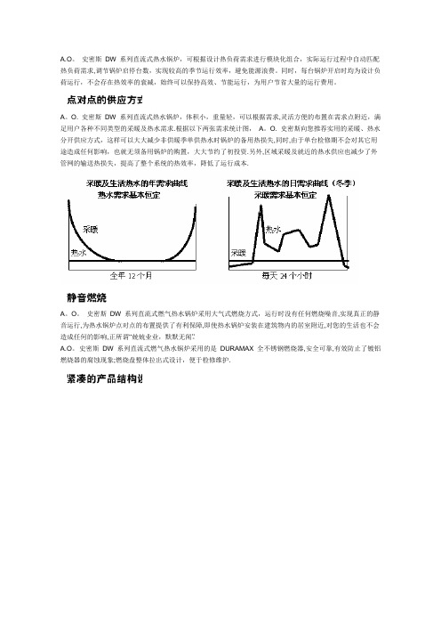
O. 史密斯DW 系列直流式热水锅炉,体积小,重量轻,可以根据需求,灵活方便的布置在需求点附近,满足用户各种不同类型的采暖及热水需求.根据以下两张需求统计图,A。
O. 史密斯向您推荐实用的采暖、热水分开供应方式,这样可以大大减少非供暖季单供热水时锅炉的备用热损失,同时,由于单台检修期不会对其它用途造成任何影响,也就无须备用锅炉的购置,大大节约了初投资.另外,区域采暖及就近的热水供应也减少了外管网的输送热损失,提高了整个系统的热效率,降低了运行成本.A。
O。
史密斯DW 系列直流式燃气热水锅炉采用大气式燃烧方式,运行时没有任何燃烧噪音,实现真正的静音运行,为热水锅炉点对点的布置提供了有利保障,即使热水锅炉安装在建筑物内的居室附近,对您的生活也不会造成任何的影响,正所谓“兢兢业业,默默无闻”。
A.O。
史密斯DW 系列直流式燃气热水锅炉采用的是DURAMAX 全不锈钢燃烧器,安全可靠,有效防止了镀铝燃烧器的腐蚀现象;燃烧盘整体拉出式设计,便于检修维护.A。
O。
史密斯DW 系列直流式燃气热水锅炉采用的是独特的全铜制热交换器,每根铜翅片管均为整根铜管经特殊加工而成,翅片与铜管为一个整体,并非后期压制而成,保证最佳的热量传递。
铜的热交换系数为350 W/M 2*℃,远远高于普通钢板材料的换热系数50W/M 2* ℃,并且,由于加工出的整体式翅片,大大增加了换热面积,换热系数更是得到了数倍的增加。
A.O。
史密斯DW 系列直流式燃气热水锅炉所采用的全铜热交换器为双层结构,上下两层交错排列,上层全铜热交换器上覆盖有折流片。
这样,保证高温烟气必须自折流环绕两层全铜热交换器流动,充分利用了热交换器的换热表面,增加了换热面积,提高了热交换器的换热效率.A。
Unitherm M.A.S燃烧器的特点及应用

Unitherm M.A.S燃烧器的特点及应用
薛俊东;杨得芹
【期刊名称】《水泥》
【年(卷),期】2012()3
【摘要】我公司承建的匈牙利NOSTRA 2 500t/d生产线采用单系列五级预热器和RSP分解炉,窑规格为Φ4m×60m,配有德国IKN公司的Pendulum篦冷机燃料使用石油焦,点火及升温时用天然气。
燃烧器采用奥地利Unitherm公司的M.A.S 燃烧器,可以100%使用烟煤、无烟煤及石油焦,同时可以加入固体废料在生产中的应用效果较好,本文对其特点及应用作一介绍。
【总页数】3页(P41-43)
【作者】薛俊东;杨得芹
【作者单位】中材建设有限公司调试服务部;鞍山冀东水泥有限责任公司
【正文语种】中文
【中图分类】TQ172.625.3
【相关文献】
1.节能环保型燃烧器技术特点分析及应用
2.飞机防火试验用油燃烧器的应用及特点介绍
3.旋流燃烧器与直流燃烧器的特点比较及发展前景
4.节能环保型燃烧器技术特点分析及应用
因版权原因,仅展示原文概要,查看原文内容请购买。
sofa燃烧器

sofa燃烧器Sofa燃烧器引言:在现代家居装饰中,沙发作为家居空间的重要组成部分,扮演着舒适、放松和时尚的角色。
然而,尽管沙发在我们生活中扮演着如此重要的角色,它们也可能成为火灾的源头。
为了解决这个问题,设计师和科学家们开发了一种新型的消防设备——Sofa燃烧器。
本文将介绍Sofa燃烧器的原理和工作机制,并探讨其在家庭和公共场所的应用。
1. Sofa燃烧器的原理和工作机制Sofa燃烧器是一种智能型消防装置,其主要作用是在沙发燃烧发生时迅速抑制火势并减少火灾的危害。
它采用了先进的传感技术和灭火剂喷射系统,能够迅速识别沙发燃烧的迹象,并自动启动灭火过程。
Sofa燃烧器的传感技术包括烟雾传感器和温度传感器。
当沙发燃烧时,烟雾传感器会检测到烟雾的存在,而温度传感器可以探测到异常高温。
一旦传感器检测到火灾迹象,Sofa燃烧器会立即启动灭火装置。
灭火装置通常由消防喷头和灭火剂组成。
消防喷头会根据火势的大小和位置进行精确喷射,将灭火剂喷洒到火源附近。
灭火剂通常使用无毒、无腐蚀性的化学物质,如干粉或气体。
2. Sofa燃烧器在家庭中的应用家庭是使用沙发最频繁的场所之一,也是火灾最容易发生的地方。
因此,在家庭中安装Sofa燃烧器可以大大减少由沙发燃烧引起的火灾的危险。
Sofa燃烧器可以在火灾发生时迅速启动,有效地扑灭火源,并降低火灾蔓延的风险。
此外,Sofa燃烧器还具有智能联动功能,可以与家庭安防系统相连。
一旦Sofa燃烧器启动,它会向家庭安防系统发送信号,触发警报并通知家庭成员和相关部门。
这种智能联动功能进一步增强了家庭的火灾安全性。
3. Sofa燃烧器在公共场所中的应用除了家庭,Sofa燃烧器还可以广泛应用于公共场所,如剧院、娱乐场所和写字楼等。
由于公共场所人流量大且人员分散,一旦火灾发生,疏散和灭火都变得更加困难。
Sofa燃烧器的安装可以提供一种有效的消防解决方案,帮助减少人员伤亡和财产损失。
在公共场所的应用中,Sofa燃烧器还可以与建筑消防系统和紧急疏散通道相结合。
- 1、下载文档前请自行甄别文档内容的完整性,平台不提供额外的编辑、内容补充、找答案等附加服务。
- 2、"仅部分预览"的文档,不可在线预览部分如存在完整性等问题,可反馈申请退款(可完整预览的文档不适用该条件!)。
- 3、如文档侵犯您的权益,请联系客服反馈,我们会尽快为您处理(人工客服工作时间:9:00-18:30)。
史密斯公司5000t/d燃烧器介绍1.丹麦史密斯公司简介众所周知,史密斯全球公司是世界上最大的水泥专业公司。
它不仅提供水泥工厂的成套设计,而且研发各种顶尖的水泥装备,它是引领世界水泥工业的先驱。
从1906年开始,该公司就向中国唐山启新洋灰公司提供了回转窑和磨机,在100多年的历史中,史密斯公司向中国市场提供了很多水泥生产线和各种装备,对中国水泥工业的发展起到了推动作用。
特别是近20年,史密斯公司在中国市场上的发展更为抢眼。
他们向中国最大的水泥集团-海螺集团提供四套10000t/d的水泥装备,它们包括生料磨、回转窑和窑尾系统,该生产线是中国最大,也是世界上目前单线最大生产能力的生产线。
史密斯公司经过多年的开发和研究,向世界水泥市场推出了一批性能优良、质量可靠和能力大的水泥装备,通过不断的改进和完善,他们越来越被更多的用户所选用。
目前,史密斯公司向中国市场提供的主要设备如下:ATOX辊磨用于粉磨水泥原料;OK辊磨用于粉磨水泥或矿渣;SF-推动棒式冷却机和多福乐喷煤管。
史密斯公司尽最大努力不断为中国水泥工业发展作出贡献。
史密斯机械工业(青岛)有限公司位于青岛市城阳区空港工业园,是著名水泥设备供应商--丹麦斯密斯公司在中国设立的全资子公司,公司资本为660万美元。
公司建于2000年,全公司职工130人,其中外国专家4人。
公司设备先进齐全,有CNC等离子数控切割机车床、铣床、刨床、卷板机、锯床、摇臂转床、Co2气体保护焊、氩弧焊等各种设备。
史密斯机械工业(青岛)有限公司全部采用丹麦技术,由总部精心设计产品,生产制造部门运用各种新工艺技术,精心检测运用X射线等无损检测设备,使产品具有可靠的品质保证并达到国际先进水平。
史密斯机械工业(青岛)有限公司主要产品为SF型推动棒式冷却机、DUOFLEX 燃烧器。
SF型冷却机具有热效率高,便于安装,维护费用低等特点,是我公司的专利产品。
DUOFLEX 燃烧器具有火焰强劲有力,易于调整,可使用于各种煤质及其它燃料。
2.DUOFLEX燃烧器介绍Duoflex系列燃烧器是水泥窑和分解炉专用燃煤设备,系丹麦史密斯公司(F.L. Smidth&A/S)积累以往20多年的多通道燃烧器设计和使用经验,于1997年新近发展出来的第三代燃烧器,代表了当今世界上最先进的水泥生产用燃烧器水平。
多福乐燃烧器适用于燃烧煤粉、焦碳粉、原油、天然气或它们的混合物。
如经过特殊改进,可用于与塑料碎片、废轮胎、垃圾、木屑和污泥等替代燃料一同燃烧,是环保产品。
燃烧器的最大发热能力从20mW到250mW,能够满足各种回转窑的煅烧要求。
它的设计理念是:中心为气体和液体燃料混合通道,用于点燃固体或液体燃料。
它外部的环形通道用来输送煤粉。
煤粉通道外面是两个同心风道,一个提供径向风,另一个提供轴向风,两股气流在通过燃烧器前部的锥形喷嘴处混合在一起。
这样可保证空气中的氧充分燃烧不形成CO。
由于温度较高,过剩空气少,其产生的NO也低。
由于多福乐燃烧器的独特性能,它越来越被广大用户所选用。
为确保在中国史密斯机械工业(青岛)有限公司(F. L. Smidth Machinery Industry (Qingdao) Co. Ltd.)生产的产品具有在丹麦生产的产品同等质量,每台燃烧器都由丹麦总部根据具体用户的燃料情况及使用条件进行设计;所有耐热、耐磨钢材和无机材料均从国外进口;位置调整机构以及伸缩节等关键部件也从丹麦总部直接进口。
燃烧器主要由以下几部分构成:1)多福乐窑用燃烧器:燃烧器主体2)移动小车:悬挂式/地面式3)燃油系统:5m3油箱(供图)/ 供油泵站/ 油量控制盘/ 点火油枪3. Duoflex 燃烧器的主要技术特点简单坚固的结构●煤风管道内置,从外向内依次为射流风管、旋流风管、输煤风管及中心保护管。
精心设计的连接结构使得射流风管和旋流风管同轴相套、多点支撑,浑然一体,有效地避免了燃烧器头部因受高温作用可能发生的弯曲。
●一次风通道(空气喷嘴)面积可调, 整个燃烧器内部仅有一个相对移动面。
通过调节手轮使煤风管伸缩, 一次风通道面积变化比为 1:2, 从而实现一次风喷出口速度大范围(1:2)调节;且可准确定、复位。
●结构简单、移动灵活的移动小车可灵活地实现喷煤管头部上下、左右及前后移动和定位。
●多重强度结构设计,确保足够钢度,内外风管做成一体,使燃烧器燃烧器强度大增,不容易变形弯曲.运行卓越的性能●旋流叶片内置, 射流/旋流风出口前混合合并后, 经锥形口喷出. 确保燃烧器产生强大的推力,从而强化煤粉与空气的混合, 使煤粉燃烧充分。
●火焰集中有力, 温度高火焰强。
燃烧器燃料在火焰中心喷入,确保了火焰不发散.煤风内置确保火力集中有力。
●输煤管内置,可确保在整个燃烧过程内煤粉始终富集于火焰中芯,沿轴线发展,十分有利于形成一个集中、有力,长度大范围可调的火焰。
这对熟料煅烧、窑皮形成和保持,以及降低窑筒体温度都十分必要。
●多福乐燃烧器使用寿命长。
风道出口为整体环状,无间隔体。
从而保证一次风高速喷出时,无气流扰动,可有效避免喷嘴的磨损。
●该燃烧器操作简单, 易于客户掌握调整要领。
从而使燃烧器形成良好的火焰形状,满足熟料煅烧要求。
●一次风用量仅为理论燃烧用风量的6-10%(如按实际用风计算则小于此值),较以往普通三通道燃烧器节省热能 8~12 Kcal/kgcl。
● 2500mmH2O的一次风压可保证火焰根部动量达2000m/s%以上,从而有效地保证了火焰强劲有力,形状调整灵活,广泛适应各种燃煤。
●设置大直径的中心管,除可在火焰根部构成钝体,除利于稳定火焰外,还为加装辅助燃烧头、废料燃烧头提供了通道。
辉煌的销售业绩●从1997年至今10年时间里,FLS公司在世界范围内就售出三百玖拾多台Duoflex 燃烧器。
由史密斯青岛公司生产,在国内售出的多福乐燃烧器就达230余台,另有30多台出口。
3. Duoflex 5000T/D窑用燃烧器技术说明及供货范围3.1 技术参数设备名称:Duoflex 燃烧器用途:用于带分解炉的5000t/d级回转窑内的煤粉燃烧型号:DBC-220-550-8.0规格:Φ550 x 8000 mm燃烧能力:12t/h,(Max. 18t/h)生产厂家:史密斯机械工业(青岛)有限公司回转窑回转窑产量: 5000(Max.6000)t/d水泥熟料单位热耗:3051 kj/kg窑/炉燃烧比: 40/60 %/ %冷却机型式:篦式冷却机回转窑规格: dia. 4.8x72m回转窑斜度: 3.5%海拔高度: 100m窑头送煤粉风量:m3/min Pa燃料柴油发热量: 9569 kcal/kg粘度: 3-4 cst煤粉净热值: kj/kg ( kcal/kg)细度: < 5% 0.08 mm 筛余水分: 0.5%温度: 50~80 ℃挥发份: %灰份: %Duoflex 燃烧器型号: Duoflex DBC-220-550-8.0燃烧器直径:550 mm (金属部分)浇铸料的长度:8000 mm浇铸料的厚度:80 mm喷咀结构:见所附样本连接管:煤粉用橡胶管;一次风用金属软管燃烧器能力:燃煤 Max. 18t/h调节范围: 10~100 %点火油枪: 120~1200 L/h燃烧器抗冲击压力:8 bar煤通道压力降:~130mbar煤风比:3-5kg/Nm3轴向风/径向风: 70~100/0~30 %燃烧器支撑形式:地面式/悬挂式燃烧器移动范围:根据用户需要燃烧器上、下、左、右摆角:2.5 度,燃烧器材质:进口高级耐热钢/耐磨钢/普通钢移动小车功率:减速电机 1.5 kW燃烧器总重:~8t油点火装置油箱: 5 m3油泵站: 1200 l/hr, 8-10kg/cm2 油量控制盘: 120~1200 l/hr油枪: 120~1200 l/hr一次风机形式:罗茨风机型号:进风口流量: 165 m3/min风压: 29.4kPa电动机:调速方法;变频事故冷却风机形式:离心风机型号: 9-26No.4A流量: 2440Nm3/h压力: 3332Pa电动机:型号: Y132S1-2功率: 5.5kW转速: 2900rpm电气要求控制电源:220V 1ph 50Hz动力电源:380V 3ph 50Hz电机防护等级:柴油雾化气源压力:max 7 barmin 5.5bar用气量: 1.5 m3/min3.2 供货范围及主要零部件规格I、卖方供货部分:(1) 窑用Duoflex燃烧器数量:1套包括:1-燃烧器, 主要有由外部套管,射流风、旋流风、煤风管及中心风管构成的燃烧器主体。
1-燃烧器头部, 用高级耐热钢制造且易于更换;1-燃烧器一次风通道位置调节、指示装置用于一次风出口面积调整,以便能调节一次风速,以达到适合于窑的火焰形状。
1一次风入口金属短管附带:1-旋流风手动调节阀;1-射流风手动调节阀;使用蜗轮蜗杆机构可确保对旋流和射流风量的精确调节和定位 1-煤风入口短管及所附耐磨材料(DENSIT) ;1-用于放置油枪的中心套管;1-用于旋流和射流风压力测量的压力表;1-煤风输送橡胶软管1-一次风金属软管1套-浇铸料用把钉(2) 移动小车: 1套(3) 燃油系统: 1套1-5 m3油箱(供图)1-供油泵站1-油量控制盘1-燃油枪II、买方采购部分●一次风机及事故风机●风机至燃烧器连接钢性风管及阀门●燃烧器移动小车用轨道和支架●燃烧器耐火浇铸料4. 质量保证期●燃烧器质保期为投产后12个月或交货后18个月,以先到为准。
5. 计制造标准及主要技术要求∙按丹麦FLS公司标准制造和中国国家制造标准;∙卖方所提供产品,在出厂前完成最终油漆;∙指示仪表的精度等级优于1.5级;压力开关的精度等级优于1级;∙每一个燃烧器均由总部专家根据用户提供的燃料情况及烧成系统工艺配置进行设计。
燃烧器的最终规格以史密斯公司丹麦总部作出的设计图纸为准。
