2104国家增压技术论坛-Semi-solid moulding technology for making automotive turbocharge compressor
智能工作面液压支架电液控制系统端头控制器设计

智能工作面液压支架电液控制系统端头控制器设计张晓海1,2, 田慕琴1,2, 张敏龙3, 宋建成1,2, 许春雨1,2, 聂鸿霖1,2, 杨永锴1,2(1. 太原理工大学 矿用智能电器技术国家地方联合工程实验室,山西 太原 030024;2. 太原理工大学 煤矿电气设备与智能控制山西省重点实验室,山西 太原 030024;3. 晋能控股装备制造集团金鼎山西煤机有限责任公司,山西 晋城 048006)摘要:随着无人值守智能化综采工作面建设的不断推进,对液压支架电液控制系统的自动化控制功能提出了更高的技术要求。
基于目前国内开发的电液控制技术在满足智能化生产技术要求方面,存在通信速率低、响应不及时和可靠性差等问题,开发了一种基于32位处理器的液压支架电液控制系统端头控制器,设计了基于工业以太网和CAN 总线的端头控制器通信架构。
根据无人值守智能化综采工作面具有智能感知、智能决策和自动控制的技术要求,在端头控制器中设计了参数巡检、参数修改、在线升级和跟机自动控制功能。
为了应对智能化综采工作面对液压支架电液控制系统数据标准化、规范化的要求,端头控制器可以对液压支架电液控制系统产生的数据按照基于位号的数据编码标准进行编码。
通过综采工作面“三机”实验平台进行实验,结果表明:端头控制器从发出巡检指令到接收到实验平台27台支架控制器的数据,整个过程用时1.8 s ,比使用RS485通信实现参数巡检快1.5 s ;端头控制器发送的升级程序大小为38 KiB ,传输时间为1.2 s 。
经过测试,综采工作面所有支架控制器从接收升级命令到一起升级成功用时为4~6 s ,达到了预期目标;端头控制器可以根据采煤机位置控制相应液压支架做出正确动作,且能够满足实时性要求。
关键词:端头控制器;ARM 处理器;电液控制系统;液压支架;智能化工作面中图分类号:TD355 文献标志码:ADesign of end controller for the electrohydraulic control system of intelligent working face hydraulic supportZHANG Xiaohai 1,2, TIAN Muqin 1,2, ZHANG Minlong 3, SONG Jiancheng 1,2,XU Chunyu 1,2, NIE Honglin 1,2, YANG Yongkai 1,2(1. National and Provincial Joint Engineering Laboratory of Mining Intelligent Electrical Apparatus Technology,Taiyuan University of Technology, Taiyuan 030024, China ; 2. Shanxi Key Laboratory of Mining Electrical Equipment and Intelligent Control, Taiyuan University of Technology, Taiyuan 030024, China ; 3. Shanxi Jincheng AnthraciteMining Group Jinding Mining and Machinery Co., Ltd., Jincheng 048006, China)Abstract : With the continuous promotion of the construction of unmanned automated fully intelligent mechanized working faces, higher technical requirements have been put forward for the automation control function of the hydraulic support electrohydraulic control system. The electrohydraulic control technology developed in China has problems such as low communication speed, delayed response, and poor reliability in meeting the requirements of intelligent production technology. An end controller for the electrohydraulic control system of hydraulic support based on a 32-bit processor has been developed. A communication architecture of the end controller based on industrial Ethernet and CAN bus has been designed. According to the technical收稿日期:2023-06-09;修回日期:2023-07-25;责任编辑:王晖,郑海霞。
2104国家增压技术论坛-InletSwirlOnCompressorPerformance_Lei Huang

9 Presentation at Turbocharging Seminar 23-24 Sept, 2014, Tianjin
nlett proprietary
NLETT
Inlet Swirl on Compressor Performance
P02/P01 = [1+(Dh0/h01)ht-t]g/g-1 , Dh0 = h02-h01 Dh0 = U2Cq2 – U1Cq1 = wR2[Cq2-(R1/R2)Cq1] ht-t =f(Ma1, i)
3 Presentation at Turbocharging Seminar 23-24 Sept, 2014, Tianjin
nlett proprietary
NLETT
Inlet Swirl on Compressor Performance
Experimental results – Positive swirl
Improved stability and efficiency
Reduced choke flow
rl
nlett proprietary
NLETT
Inlet Swirl on Compressor Performance
Loss mechanism of negative swirl at chock end
Entropy at 90% and 50% span, 50krpm and 53% mass flow
• Vane number, meridional shape, vane angle distribution, distance to impeller etc were optimised by CFD
superFlashMemory
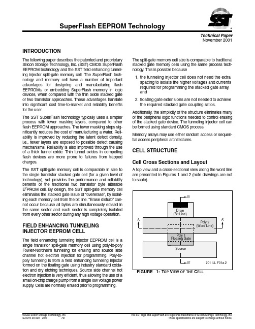
The split-gate memory cell size is comparable to traditional stacked gate memory cells using the same process technology. This is possible because
1. the tunneling injector cell does not need the extra spacing to isolate the higher voltages and currents required for programming the stacked gate array, and
SMC EX260-SEC1 -SEC2 -SEC3 -SEC4 商品说明书
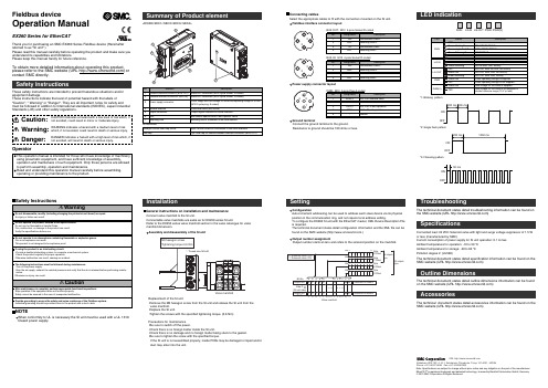
<EX260-SEC1/-SEC2/-SEC3/-SEC4>InstallationConfigurationAuto-increment addressing can be used to address each slave device via its physical position in the communication ring, and not require local address setting.To configure the EX260 SI unit with the EtherCAT master, XML Device Description File is required.The technical document states detail configuration information and the XML file can be found on the SMC website (.)Output number assignmentOutput number starts at zero and refers to the solenoid position on the manifold.General instructions on installation and maintenanceConnect valve manifold to the SI unit.Connectable valve manifolds are same as for EX250 series SI unit.Refer to the EX250 series valve manifold section in the valve catalogue for valvemanifold dimension.Power supply connector layoutGround terminalConnect the ground terminal to the ground.Resistance to ground should be 100 ohms or less.SettingReplacement of the SI unit•Remove the M3 hexagon screw from the SI unit and release the SI unit from the valve manifold.•Replace the SI unit.•Tighten the screws with the specified tightening torque. (0.6 Nm)Precautions for maintenance •Be sure to switch off the power.•Check there is no foreign matter inside the SI unit.•Check there is no damage and no foreign matter being stuck to the gasket.•Be sure to tighten the screw with the specified torque.If the SI unit is not assembled properly, inside PCBs may be damaged or liquid and/or dust may enter into the unit.Connecting cablesSelect the appropriate cables to fit with the connectors mounted on the SI unit.Fieldbus interface connector layoutTroubleshootingThe technical document states detail troubleshooting information can be found on the SMC website (URL )SpecificationsConnected load: 24VDC Solenoid valve with light and surge voltage suppressor of 1.5 W or less (manufactured by SMC)Current consumption of power supply for SI unit operation: 0.1 A max.Ambient temperature for operation: -10 to 50 ℃Ambient temperature for storage: -20 to 60 ℃Pollution degree 2: (UL508)The technical document states detail specification information can be found on the SMC website (URL )Akihabara UDX 15F, 4-14-1, Sotokanda, Chiyoda-ku, Tokyo 101-0021, JAPAN Phone: +81 3-5207-8249 Fax: +81 3-5298-5362URL Outline DimensionsThe technical document states detail outline dimensions information can be foundon the SMC website (URL )AccessoriesThe technical document states detail accessories information can be found on the SMC website (URL )*2: Single flash pattern*1: Blinking patternAssembly and disassembly of the SI unit*3: Flickering patternNOTEWhen conformity to UL is necessary the SI unit must be used with a UL 1310Class2 power supply.Fieldbus deviceOperation ManualEX260 Series for EtherCATThank you for purchasing an SMC EX260 Series Fieldbus device (Hereinafter referred to as "SI unit" ).Please read this manual carefully before operating the product and make sure you understand its capabilities and limitations.Please keep this manual handy for future reference.To obtain more detailed information about operating this product,please refer to the SMC website (URL ) or contact SMC directly.These safety instructions are intended to prevent hazardous situations and/or equipment damage.These instructions indicate the level of potential hazard with the labels of"Caution", " Warning" or "Danger". They are all important notes for safety and must be followed in addition to International standards (ISO/IEC), Japan Industrial Standards (JIS) and other safety regulations.OperatorNote: Specifications are subject to change without prior notice and any obligation on the part of the manufacturer.EtherCAT ®is registered trademark and patented technology, licensed by Beckhoff Automation GmbH, Germany.© 2010 SMC Corporation All Rights ReservedPWR: M12 5-pole Plug A-coded。
ASTM标准材质对照
ASTM钢管标准对照:l.r5?+f4d,n8]1f(Q$QA323-93(2000)硼铁规格A324-73(2000)钛铁合金三维|cad|机械汽车技术|catia|pro/e|ug|inventor|solidedge|so lidwor s|caxa)D4u:|-_&m!B7p#?!T/|A325-00经热处理最小抗拉强度为120/105ksi的钢结构螺栓三维网技术论坛5z(F#f9I3F9M&Q9E"tA325M-00结构钢连接件用高强度螺栓(米制)A327-91(1997)铸铁冲击试验方法三维网技术论坛6^0N+Y;f:P+d*I;^5])c!w0L3E+P:dA327M-91(1997)铸铁冲击试验方法(米制)三维网技术论坛9|)e!y9u#?3C2lA328/A328M-00薄钢板桩三维网技术论坛;V(P(~%s8U:J!D:_A331-95(2000)冷加工合金钢棒+n-h+G#Pj-W9r三维网技术论坛8L0p,Z+`;v.z6NA333/A333M-99低温用无缝与焊接钢管规格A334/A334M-99低温设备用无缝与焊接碳素和合金钢管三维,cad,机械技术汽车,catia,pro/e,ug,inventor,solidedge,solidwor s,caxa,时空镇江3P4B;l$_'L0J3r6@7z"q8\4H;`+N9\A335/A335M-01高温用无缝铁素体合金钢管A336/A336M-99e1压力与高温部件用合金钢锻件规格A338-84(1998)铁路,船舶和其他重型装备在温度达到650华氏度(345摄氏度)时使用的可锻铸铁法兰,管件和阀门零件三维网技术论坛8j&q7p$[9`*Z+PA34/A34M-96磁性材料的抽样和采购试验的标准惯例3I:c&v,~+hP%]4i0z'S)G*U&i6L8R.S,H)q3u+UA340-99a有关磁性试验用符号和定义的术语2b"@8F7O:vh/n6O9A341/A341M-00用直流磁导计和冲击试验法测定材料的直流磁性能的试验方法三维网技术论坛#]6ZQ"~1w4Z三维网技术论坛*~6Z+~,|5o7K/P,O%BA342/A342M-99磁铁材料导磁率的试验方法&z-Op&g-o7T6c*KA343-97在电力频率下用瓦特计-安培计-伏特计法(100-1000赫兹)和25厘米艾普斯亭(EPSTEIN)机架测定材料的交流电磁性能的试验方法三维,cad,机械技术汽车,catia,pro/e,ug,inventor,solidedge,solidwor s,caxa,时空镇江B&B:e&Z;[:k6@A345-98磁设备用平轧电炉钢A348/A348M-00用瓦特计--安培计--伏特计法(100-10000赫兹)和25厘米艾普斯亭框测定材料的交流磁性能的试验方法A350/A350M-00c要求进行缺口韧性试验的管道部件用碳素钢与低合金钢锻件技术规范0c%E+{:G/yA351/A351M-00容压零件用奥氏体及奥氏体铁素体铸铁的技术规范三维网技术论坛7Q;N2^3q+e/{5@/@3VA352/A352M-93(1998)低温受压零件用铁素体和马氏体钢铸件规格三维|cad|机械汽车技术|catia|pro/e|ug|inventor|solidedge|solidwor s|caxa2z/Z6C*I/z4X2T!~A353/A353M-93(1999)压力容器用经二次正火及回火处理的含9%镍的合金钢板A354-01淬火与回火合金钢螺栓,双头螺栓及其他外螺纹紧固件规格三维网技术论坛8A:A4n!A7S6H0HA355-89(2000)渗氮用合金钢棒"J5j_3q1{+x*@+J(Y6U6E4^6`'L;T%gA356/A356M-98e1蒸汽轮机用厚壁碳素钢、低合金钢和不锈钢铸件三维,cad,机械技术汽车,catia,pro/e,u g,inventor,solidedge,solidw or s,caxa,时空镇江;z:E2}5b,vfA358/A358M-01高温用电熔焊奥氏体铬镍合金钢管三维|cad|机械汽车技术|catia|pro/e|ug|inventor|solidedge|solidwor s|caxasm'a8E.E8H6z#[A36/A36M-00a碳素结构钢技术规范三维网技术论坛)^6X:m*j'I)x0f$NA363-98地面架空线用镀锌钢丝绳&T6S:n!@3K5X:_:A}J三维网技术论坛4l2|2K2s9t4R4\$MA367-60(1999)铸铁的激冷试验方法1G/z/e;K9s0g:YA368-95a(2000)不锈钢和耐热钢丝绳的标准-s7R+I2H3N$d2A369/A369M-01高温用锻制和镗孔碳素钢管和铁素体合金钢管三维网技术论坛2O6N4}"{-f!lA370-97a钢制品机械测试的标准试验方法和定义A372/A372M-99薄壁压力容器用碳素钢及合金钢锻件三维,cad,机械技术汽车,catia,pro/e,u g,inventor,solidedge,solidw orks,caxa,时空镇江9{3Y3]0^,c1B)f#@1L'l9It5a&WA376/A376M-01高温中心站用无缝奥氏钢管A377-99球墨铸铁压力管规范索引三维网技术论坛0G6i7,w!dA380-99e1不锈钢零件、设备和系统的清洗和除垢三维|cad|机械汽车技术|catia|pro/e|ug|inventor|solidedge|solidwor s|caxa,m4T.`3g$c三维网技术论坛0I(e2x2E+r/y I:`,G+N^/vA381-96高压输送用金属弧焊钢管9P#N*l(w)J*ec5H,p$vRA384-76(1996)防止钢组件热浸镀锌时翘曲和扭曲用安全保护A385-00提供高质量镀锌覆层(热浸)三维网技术论坛"G4,g-^.h(O2EA3-01低、中、高碳素钢鱼尾(连接)板三维,cad,机械技术汽车,catia,pro/e,u g,inventor,solidedge,solidw or s,caxa,时空镇江-t(F0F4W8T1O[:k%d(].{3JA387/A387M-99e1压力容器用铬钼合金钢板6K"s,~%P7b三维网技术论坛#D-n:R7_#L,m#hA388/A388M-95(2000)e1重型钢锻件超声波检测A389/A389M-93(1998)适合高温受压部件用经特殊热处理的合金钢铸件规格三维网技术论坛2s3D/H*~'R6h9n7Z8s4nA390-95(2001)饲养家禽用镀锌钢丝栏栅网(六角形和直线形)A391/A391M-9880号合金钢链条三维,cad,机械技术汽车,catia,pro/e,u g,inventor,solidedge,solidw orks,caxa,时空镇江9V7R.N't#|4t,ax三维网技术论坛F%q0n:A)IA392-96镀锌钢丝链环栏栅网三维|cad|机械汽车技术|catia|pro/e|ug|inventor|solidedge|solidwor s|caxa2[K2WZ.G#a9C8d三维|cad|机械汽车技术|catia|pro/e|ug|inventor|solidedge|so lidwor s|caxa9Z'A8a7L-i&@#F,h#xA394-00传动塔架用镀锌和裸露钢螺栓A395/A395M-99高温用铁素体球墨铸铁受压铸件三维网技术论坛4Z'~+M#b%U%B:RA400-69(2000)钢棒的成分及机械性能选择指南三维,cad,机械技术汽车,catia,pro/e,u g,inventor,solidedge,solidw or ks,caxa,时空镇江*c4n!z4g$F8|1a)|&t*^三维网技术论坛6p0s3\T-i0u5N0zA401/A401M-98铬硅合金钢丝!t!v(s'{+^*j/YA403/A403M-00b锻制奥氏体不锈钢管配件A407-93(1998)盘簧用冷拉钢丝三维网技术论坛;[9O;^7K8k4GA409/A409M-01腐蚀场所或高温下使用的焊接大口径奥氏体钢管三维|cad|机械汽车技术|catia|pro/e|ug|inventor|solidedge|so lidwor s|caxa2G4L/w%o&N1QA411-98镀锌低碳钢铠装线9A4i;n.j/f7A'Q(~A413/A413M-00碳素钢链A414/A414M-00压力容器用碳素薄钢板A416/A416M-99预应力混凝土用无涂层七股钢铰线A417-93(1998)之字型、方型和正弦型装垫弹簧元件用冷拉钢丝A418-99涡轮机及发电机钢转子锻件的超声波检查方法三维,cad,机械技术汽车,catia,pro/e,ug,inventor,solidedge,solidwor s,caxa,时空镇江&V6v-MP-[$l'^5v7o1L#y三维网技术论坛%y/Z5[2tm0~.t:XA420/A420M-00b低温下用锻制碳素钢和合金钢管配件三维|cad|机械汽车技术|catia|pro/e|ug|inventor|solidedge|solidwor s|caxa"t&Z.k%o,h$P6p$V2K/i*m2v8E)w"S;U/e!P5])kA421/A421M-98a预应力混凝土用无涂层消除应力钢丝的技术规范三维,cad,机械技术汽车,catia,pro/e,ug,inventor,solidedge,solidwor s,caxa,时空镇江)J;@.V/f9~2y8vA423/A423M-95(2000)无缝和电焊低合金钢管A424-00搪瓷用钢薄板三维|cad|机械汽车技术|catia|pro/e|ug|inventor|s olidedge|solidwor s|caxa%r(G1R$O6s三维,cad,机械技术汽车,catia,pro/e,ug,inventor,solidedge,solidwor s,caxa,时空镇江'~,}{#a(CP3?;~A426-92(1997)高温用离心铸造的铁素体合金钢管8I5M.c:Z;~-k,V2iA427-74(1996)e1冷轧和热轧用锻制合金钢辊三维网技术论坛/B2v)n#C7j1n(I-RA428/A428M-01钢铁制品上铝覆层重量的测试方法三维网技术论坛-Z:m6\2z-G6v$[7\9C:e)v;^3dA434-90a(2000)热轧与冷精轧经回火及淬火的合金钢棒三维,cad,机械技术汽车,catia,pro/e,u g,inventor,solidedge,solidw orks,caxa,时空镇江1N+a#y2\:_三维网技术论坛+J`-`,]!h1W$B5m+c!F*aA435/A435M-90(2001)钢板的直射束纵向超声波检验三维网技术论坛#w1A0w!E5M2_A436-84(1997)e1奥氏体灰口铁铸件A437/A437M-01高温用经特殊处理的涡轮型合金钢螺栓材料A438-80(1997)灰铸铁横向弯曲试验A439-83(1999)奥氏体可锻铸铁铸件A447/A447M-93(1998)高温用镍铬铁合金钢铸件(25-12级)三维网技术论坛/B:r#f1@2M8XLA449-00经淬火和回火的钢螺栓和螺柱三维网技术论坛4r"\/f0U2m;l2c8p三维网技术论坛"s2r2h([,a$e2LA450/A450M-96a碳素钢管、铁素体合金钢管及奥氏体合金钢管三维,cad,机械技术汽车,catia,pro/e,ug,inventor,solidedge,solidwor s,caxa,时空镇江(r"Z&c-t-Y:v)H%_0{/R:`A451-93(1997)高温用离心铸造的奥氏体钢管三维,cad,机械技术汽车,catia,pro/e,ug,inventor,solidedge,solidwor s,caxa,时空镇江B'd"`/m$B1^7FA453/A453M-00具有同奥氏体钢相类似的膨胀系数、屈服强度为50-120Ksi(345-827MPa)的耐高温螺栓材料三维网技术论坛"W0g&v9~-e!^'R3D;L)G/]A455/A455M-90(2001)压力容器用高强度碳锰钢板A456/A456M-99大型曲轴锻件的磁粉检查,x?+P0].GA459-97镀锌平轧扁钢铠装带A460-94(1999)包铜钢丝绳标准;C&{;a4R4]8p7x.J&M三维,cad,机械技术汽车,catia,pro/e,ug,inventor,solidedge,solidwor s,caxa,时空镇江R:Be3\;gA463/A463M-00热浸镀铝薄钢板(R#N:b6f8L3K*?0B#yA466/A466M-98非焊接碳素钢链A467/A467M-98机器链和盘旋链A469-94a(1999)用于发电机转子的真空处理钢锻件A470-01涡轮机转子和轴用经真空处理的碳素钢和合金锻件三维,cad,机械技术汽车,catia,pro/e,ug,inventor,solidedge,solidwor s,caxa,时空镇江0y"\4q9[,n#C/y6h;XA471-94(1999)涡轮转子转盘和转轮用真空处理合金钢锻件技术规范三维|cad|机械汽车技术|catia|pro/e|ug|inventor|solidedge|solidwor s|caxa$b,X$z8e'H.r6W A472-98蒸汽涡轮机轴及转子锻件的热稳定性的试验方法A473-01不锈和耐热钢锻件三维,cad,机械技术汽车,catia,pro/e,u g,inventor,solidedge,solidw orks,caxa,时空镇江+R1f*N/F7U9t+}:Q1wA474-98包铝钢丝绳标准三维网技术论坛;^8eb0Q/_'y1c/M4\三维网技术论坛0j(y?.p-g"F#H4[A475-98镀锌钢丝绳三维|cad|机械汽车技术|catia|pro/e|ug|inventor|solidedge|solidwor s|caxa7H0Q.6d4A476/A476M-00造纸厂干燥辊用球墨可锻铸铁件:|8O7Z6W"z4OA478-97铬镍不锈钢和耐热钢制编织钢丝三维网技术论坛2c1B!{3h'C*@)U,n9nA479/A479M-00锅炉及压力容器用不锈钢和耐热钢棒与型材三维网技术论坛M#t;G6l(h'u三维|cad|机械汽车技术|catia|pro/e|ug|inventor|solidedge|so lidwor s|caxa:l)?6b&V'B%wA47/A47M-99铁素体可锻铁铸件三维,cad,机械技术汽车,catia,pro/e,u g,inventor,solidedge,solidw orks,caxa,时空镇江7{+a0U1`"b/J!}$n9f8uz6h.Z,gA480/A480M-01扁平轧制耐热不锈钢厚板材、薄板材和带材通用要求A481-94(2000)金属铬三维,cad,机械技术汽车,catia,pro/e,ug,in ventor,solidedge,solid work s,caxa,时空镇江9U5H!^4gC5w/{,\7P*oA482-93(2000)铬铁硅三维,cad,机械技术汽车,catia,pro/e,ug,inventor,solidedge,solidwor s,caxa,时空镇江s+}l8H4z0q)LA483-64(2000)硅锰合金三维|cad|机械汽车技术|catia|pro/e|u g|inventor|solided ge|solidwor s|caxa(H9b6y0n1e4U3q.y:_A484/A484M-00不锈及耐热锻钢棒,钢坯及锻件的规格三维|cad|机械汽车技术|catia|pro/e|ug|inventor|solidedge|solidwor s|caxa%R"L5e,[-l%V)K.n9V"Q9@dA485-00高淬透性耐磨轴承钢的技术规范7D-S4El,F)LA487/A487M-93(1998)受压钢铸件三维网技术论坛)d1n9cn&W7R$j"n9x7qA488/A488M-01钢铸件焊接规程和工作人员的合格鉴定A48-94ae1灰铁铸件三维网技术论坛)U+|$@*{(n/j4V/M5J!A3?'FA489-00碳素钢吊耳m/K.}&H6|#W)|%B,D0~"j*|A490-00最小拉伸强度为150千磅/平方英寸热处理钢结构螺栓0?+W$V4t,H3A.W(wA491-96镀铝钢链环栏栅结构三维|cad|机械汽车技术|catia|pro/e|ug|inventor|solidedge|solidwor s|caxa"{(`4w']9J3}:R.q8zA492-95(2000)耐热不锈钢丝绳)n'T1m%y+l+z8v1A:p)A493-95(2000)冷镦和冷锻不锈钢和耐热钢丝3Lh6u#_8B0@*VA494/A494M-00镍和镍合金铸件&}8C&g*K)F%f!\2V"f6bA495-94(2000)硅钙合金钢技术规范三维网技术论坛.I2a7N/w&{2T6U9w7e/sA496-97ae1钢筋混凝土用变形钢丝三维,cad,机械技术汽车,catia,pro/e,ug,inventor,solidedge,solidwor s,caxa,时空镇江9j0~!K1F2f!s0W/J7`,S/x)VA497-99e1钢筋混凝土用焊接变形钢丝网A498-98无缝与焊接碳素钢,铁素体钢与奥氏体钢制有整体散热片的换热器钢管三维网技术论坛3U3E"L32H#X 三维网技术论坛(f+?x*]:A$J!S5PA49-01经热处理的碳素钢鱼尾(连接)板,微合金鱼尾板及锻制碳素钢异型鱼尾板三维网技术论坛*x*}(_!T/r+{A499-89(1997)e1轧制丁字钢轨用的碳素钢棒材及型材的技术规范三维网技术论坛1A.h6[*E9k7C&e:R,J$q01}!QA500-01圆形与异型焊接与无缝碳素钢结构管三维,cad,机械技术汽车,catia,pro/e,u g,inventor,solidedge,solidw or ks,caxa,时空镇江i6f7v2H4e-[三维,cad,机械技术汽车,catia,pro/e,ug,inventor,solidedge,solidwor s,caxa,时空镇江8OY2_!q$B:x%v4A501-01热成型焊接与无缝碳素钢结构管三维网技术论坛&?:D(Y5j5A;P:@/c*[A503/A503M-01锻制大型曲轴的超声波检验三维网技术论坛k8[#w4T0i-h5Y1a,d三维,cad,机械技术汽车,catia,pro/e,ug,inventor,solidedge,solidwor s,caxa,时空镇江:?&T54@%p"z8`3_8A504-93(1999)锻制碳素钢轮三维|cad|机械汽车技术|catia|pro/e|ug|inventor|solidedge|solidwor s|caxa:g7x-B.o8U3SA505-00热轧和冷轧合金钢薄板和带材三维网技术论坛8q4v:G+`.I7E+}u-x+.X%r*aj;o4q1tA506-00正规质量及优质结构的热轧和冷轧合金钢薄板与带材*C"B$H5Q6vA507-00优质拉拔,热轧和冷轧合金钢薄板与带材A508/A508M-95(1999)压力容器用经回火和淬火真空处理的碳素钢与合金钢锻件3Z9s-IM.r)E.j'c A510-00碳素钢盘条和粗圆钢丝通用要求A510M-00碳素钢盘条和粗圆钢丝(米制)三维,cad,机械技术汽车,catia,pro/e,ug,in ventor,solidedge,solidwor s,caxa,时空镇江3o5C+C%y)@;s-w-tA511-96无缝不锈钢机械管三维,cad,机械技术汽车,catia,pro/e,ug,inventor,solidedge,solidwor s,caxa,时空镇江4T8O7@%n-~%w)qA512-96冷拉对缝焊碳素钢机械管三维|cad|机械汽车技术|catia|pro/e|ug|inventor|solidedge|solidwor s|caxa)h7t+`/u/e)o"vA513-00电阻焊碳素钢与合金钢机械钢管A514/A514M-00a焊接用经回火与淬火的高屈服强度合金钢板三维,cad,机械技术汽车,catia,pro/e,ug,inventor,solidedge,solidwor s,caxa,时空镇江%y$P5I!];g8R!}A515/A515M-92(1997)中温及高温压力容器用碳素钢板三维|cad|机械汽车技术|catia|pro/e|ug|inventor|solidedge|solidwor s|caxa3Y%t2?*g;r0Z三维,cad,机械技术汽车,catia,pro/e,ug,inventor,solidedge,solidwor s,caxa,时空镇江$c6Y8F#T"\3VA516/A516M-90(2001)中温及低温压力容器用碳素钢板A517/A517M-93(1999)压力容器用经回火与淬火的高强度合金钢板A518/A518M-99耐蚀高硅铁铸件三维|cad|机械汽车技术|catia|pro/e|ug|inventor|solidedge|solidwor s|caxa5X/v#]*e/c/w#I2E2W;n0b2p8VA519-96无缝碳素钢与合金钢机械管三维|cad|机械汽车技术|catia|pro/e|ug|inventor|solidedge|solidwor s|caxa"Q*G+^%gls7qA521-96一般工业用闭式模钢锻件A522/A522M-95b(2000)低温用锻制或轧制含镍8%和9%的合金钢法兰,配件,阀门和零件规格:K#o;f3?}:f;T#aA523-96高压管型电缆线路用平端无缝与电阻焊钢管A524-96常温和低温用无缝碳素钢管三维|cad|机械汽车技术|catia|pro/e|ug|inventor|solidedge|solidwor s|caxa:B.A.h"H7o&J"r1Y4_6j三维,cad,机械技术汽车,catia,pro/e,ug,inventor,solidedge,solidwor s,caxa,时空镇江9p X:D(Q&i%z$A529/A529M-00高强度碳锰结构钢质量-I9g;G0G"e.L)r*J;B5C&|.b9VZA530/A530M-99e1特种碳素钢和合金钢管三维|cad|机械汽车技术|catia|pro/e|ug|inventor|solidedge|solidwor s|caxa%w1{3_+K+@:]三维,cad,机械技术汽车,catia,pro/e,ug,inventor,solidedge,solidwor s,caxa,时空镇江M2p.V2_:b,aA531/A531M-91(1996)涡轮发电机钢定位环的超声波检验A532/A532M-93a(1999)e1耐磨铸铁三维网技术论坛!X9p)U9P/@'Z-a三维网技术论坛3l-J-g#}!'v$f&GA533/A533M-93(1999)压力容器用经回火和淬火的锰钼及锰钼镍合金钢板I%N&U1B1@$v'Z/s三维,cad,机械技术汽车,catia,pro/e,ug,inventor,solidedge,solidwor s,caxa,时空镇江:H,U0_7@-b3`5x$R2NA534-94用于耐摩擦轴承的渗碳钢'D%S'e&D(U.g1`*S#p,B7KA536-84(1999)e1球墨铸铁件A537/A537M-95(2000)压力容器用经热处理的碳锰硅钢板三维|cad|机械汽车技术|catia|pro/e|ug|inventor|solidedge|solidwor s|caxa&O8O'e9R(R%J"A#C8X0z9KA53/A53M-01无镀层热浸的、镀锌的、焊接的及无缝钢管的技术规范#L(S0t#B%b/@A539-99天然气和燃料油管线用电阻焊钢盘管三维网技术论坛"_F#c-y-t3C"rA540/A540M-00特殊用途的合金钢螺栓材料三维网技术论坛;i%g4t!d8\-A(_&WA541/A541M-95(1999)压力容器部件用经淬火和回火的碳素钢及合金钢锻件.e*\0d-m,a#C'H7k3三维网技术论坛7X&n:X"b3["[A542/A542M-99e1压力容器用经回火和淬火的铬钼、铬钼钒及铬钼钒钛硼合金钢板A543/A543M-93(1999)压力容器用经回火和淬火的镍铬钼合金钢板三维网技术论坛S-e(l3`'R三维网技术论坛8J!E6T;U;X"?,y)e)V8G*QA550-78(2000)铌铁合金三维|cad|机械汽车技术|catia|pro/e|ug|inventor|solidedge|so lidwor s|caxa/K+^$n(_4N&xA551-94(1999)钢轮箍。
模块化定子混合励磁同步电机磁网络建模与分析

第27卷㊀第12期2023年12月㊀电㊀机㊀与㊀控㊀制㊀学㊀报Electri c ㊀Machines ㊀and ㊀Control㊀Vol.27No.12Dec.2023㊀㊀㊀㊀㊀㊀模块化定子混合励磁同步电机磁网络建模与分析吴胜男,㊀庞先文,㊀佟文明,㊀王玉坤(沈阳工业大学国家稀土永磁电机工程技术研究中心,辽宁沈阳110870)摘㊀要:以一台模块化定子交替极转子结构的混合励磁同步电机为研究对象,提出了一种三维磁网络模型,综合考虑了定子齿顶局部饱和问题㊁定子槽漏磁㊁转子端部漏磁㊁轴向漏磁㊁电枢反应㊁转子转动等因素㊂利用所搭建的三维磁网络模型分别计算分析了电机的气隙磁通密度㊁磁链与电动势等特性,并通过有限元分析验证了模型的准确性,同时,还对混合励磁同步电机的性能包括调磁能力㊁电磁转矩㊁铁耗等进行了对比分析,得出了该电机调磁能力良好,在通以2A 与4A 励磁电流时,相磁链相较于无励磁时分别增加了22.68%与45.36%,而在通以-2A 与-4A 励磁电流时,相磁链分别降低了13.45%与24.9%;功率调节灵活,在低速工作时可以通过增加电励磁电流来提升电机的输出功率;以及采用非晶合金可以有效降低铁耗,提高效率的结论㊂该解析模型与有限元方法相比节约了大量时间,为更高效准确地分析混合励磁同步电机的性能提供了新的思路㊂关键词:混合励磁电机;三维磁网络;局部饱和;轴向磁路;漏磁路;有限元分析DOI :10.15938/j.emc.2023.12.010中图分类号:TM341文献标志码:A文章编号:1007-449X(2023)12-0095-10㊀㊀㊀㊀㊀㊀㊀㊀㊀㊀㊀㊀㊀㊀㊀㊀㊀㊀㊀㊀㊀㊀㊀㊀㊀㊀㊀㊀㊀㊀㊀㊀㊀㊀㊀㊀㊀㊀㊀㊀㊀㊀㊀㊀㊀㊀㊀㊀㊀㊀㊀㊀㊀㊀㊀㊀㊀㊀㊀㊀㊀㊀㊀㊀㊀㊀㊀㊀㊀㊀㊀㊀㊀㊀㊀㊀㊀㊀㊀㊀㊀㊀㊀㊀㊀㊀㊀㊀㊀㊀㊀㊀㊀㊀㊀㊀㊀㊀㊀㊀㊀㊀㊀㊀㊀㊀㊀㊀㊀㊀㊀㊀收稿日期:2022-06-16基金项目:国家自然科学基金(51907129);辽宁省科技厅项目(2021-MS -236)作者简介:吴胜男(1985 ),女,博士,副教授,研究方向为特种电机及其控制;庞先文(1998 ),男,硕士研究生,研究方向为混合励磁电机分析与优化;佟文明(1984 ),男,博士,教授,博士生导师,研究方向为高性能永磁电机及其控制;王玉坤(1995 ),男,硕士研究生,研究方向为混合励磁电机设计㊂通信作者:佟文明Modeling and analysis of magnetic network of modular statorhybrid excitation synchronous motorsWU Shengnan,㊀PANG Xianwen,㊀TONG Wenming,㊀WANG Yukun(National Engineering Research Center for Rare-earth Permanent Magnet Machines,Shenyang University ofTechnology,Shenyang 110870,China)Abstract :A three-dimensional magnetic equivalent circuit (MEC)model was proposed,which is based on a modular stator and alternating pole rotor structure motor.In this model,the local saturation problemof stator tooth top,stator slot magnetic leakage,rotor end magnetic leakage,axial leakage flux,armature reaction,rotor rotation and other factors were comprehensively considered.The three-dimensional mag-netic network model was used to calculate and analyze the characteristics of the air gap magnetic flux den-sity,flux and EMF,etc.At the same time,a comparative analysis was conducted on the performance of the hybrid excitation synchronous motor,including magnetic regulation ability,electromagnetic torque,i-ron loss,etc.It is found that the motor has good magnetic regulation ability.When applying 2A and 4A excitation currents,the phase flux is increased by 22.68%and 45.36%respectively compared with when there is no excitation,while when applying -2A and -4A excitation currents,the phase flux is decreased by 13.45%and 24.9%respectively;Power regulation is flexible,and the output power of the motor can be improved by increasing the excitation current when working at low speeds;And the conclu-sion using amorphous alloys can effectively reduce iron consumption and improve pared with the finite element method,this analytical model saves a lot of time and provides a new idea for more efficient and accurate analysis of the performance of the new HESM.Keywords:hybrid excitation motor;three-dimensional magnetic network;local saturation;axial magnetic circuit;leakage of magnetic circuit;finite element analysis0㊀引㊀言与传统的电励磁同步电机及永磁同步电机相比,混合励磁电机避免了大量的励磁损耗导致电机效率低下以及永磁体退磁的问题[1]㊂由于其具有永磁发电机无刷㊁可靠以及调压方便的优点[2],所以被广泛应用于电动混合动力汽车驱动以及风力发电等领域[3]㊂对混合励磁电机进行静态特性计算与电磁性能预测有很多种方法,包括解析法[4-7]㊁等效磁网络法[8-12]㊁有限元法等㊂解析法具有计算速度快㊁精度高㊁对计算机设备性能要求低等特点,但解析法在计算时过于简化模型,如假设了定子铁心和转子背轭磁导无穷大而导致计算无法考虑铁心材料非线性变化带来的影响,计算并不准确[13]㊂等效磁网络法采用磁路和电路类比的方法,在计算时首先考虑了电机的几何形状,同时考虑了电机漏磁㊁磁饱和㊁电枢反应和转子旋转等因素,其计算结果相对比较准确,计算过程得益于MATLAB程序的广泛应用,可以在较短的计算时间内完成相对精确的磁场计算,适用于电机初始磁场计算和优化设计[14]㊂如今,磁网络已经被广泛用于各类电机的电磁特性分析,如开关磁阻电机[15]㊁永磁无刷电机[16]㊁内置式永磁电机等[17-18]㊂文献[19]将一台轴向磁通电机径向分层,将电机简化为多个直线电机进行建模分析;文献[20]对一台混合励磁三维轴向磁通电机建立了三维磁网络模型,该模型综合考虑了磁通边缘效应㊁斜槽㊁静态和动态偏心㊁槽漏磁以及多类型激励等多方面因素㊂文献[21]磁网络模型引入考虑磁动势和反作用磁通量的分支磁路,进而引入了涡流效应㊂文献[22]提出了模块化等效磁网络建模思路和具有通用性的气隙等效磁网络模型,在气隙模型中引入了一种耦合的可变磁导单元,该单元捕获轴向和周向气隙磁通密度㊂借助于耦合可变磁导元件,通过气隙和转子的时变连接来考虑瞬态磁场㊂目前对于混合励磁电机的性能分析多以有限元方法为主,本文旨在提供一种高效准确的分析方法并避免有限元耗时长的弊端㊂以一台电动汽车用新型模块化定子交替极转子结构的新型混合励磁同步电机为研究对象,提出一种三维磁网络解析模型,模型中考虑电机的定子齿顶饱和㊁槽漏磁㊁端部漏磁㊁电枢反应㊁转子转动等因素㊂同时利用该模型计算分析新型混合励磁同步电机的气隙磁密㊁磁链㊁反电动势与电磁转矩等特性,利用有限元结果验证准确性,并计算分析新型混合励磁同步电机的调磁性能㊂1㊀混合励磁同步电机结构与工作原理1.1㊀新型混合励磁同步电机结构新型模块化定子混合励磁同步电机的基本拓扑结构如图1所示㊂定子部分采用模块化结构,定子齿与定子轭分别加工后通过燕尾槽连接,电枢绕组与励磁绕组均缠绕在定子齿上,电励磁绕组沿轴向分为两段且电流方向相反,省去了电刷与滑环结构,提高了电机的可靠性,同时电机定子侧采用非晶合金材料代替了常用的硅钢片结构,减小了电机的铁耗,提升了电机的效率㊂转子侧采用实心交替极结构,沿轴向分为两段,依次放置永磁体磁极与铁磁极,周向方向上永磁体磁极与铁磁极交错排列,铁磁极为电励磁提供通路,电机基本参数如表1所示㊂1.2㊀新型混合励磁同步电机工作原理新型混合励磁同步电机存在3种工作状态,即永磁体单独励磁状态㊁直流励磁增磁状态与直流励磁去磁状态㊂当电机工作在永磁体单独励磁状态时,直流励磁电流为0,其磁通由永磁体N极出发经过气隙㊁定子齿㊁定子周向轭部㊁定子轴向轭部回到永磁体S极,此时铁磁极不作为磁通路径;当工作在增磁状态时,周向方向上临近N极的铁磁极经磁化显 S ,临近S极的铁磁极经磁化显 N ,磁通沿周向由N极到S极,这种情况下,电机每极下磁通增强;当工作在去磁状态时,周向方向上临近N极的69电㊀机㊀与㊀控㊀制㊀学㊀报㊀㊀㊀㊀㊀㊀㊀㊀㊀㊀㊀㊀㊀第27卷㊀铁磁极经磁化显 N ,临近S 极的铁磁极经磁化显 S ,磁通沿轴向由N 极到S 极,这种情况下,电机每极下磁通减弱,如图2所示㊂图1㊀混合励磁同步电机基本拓扑结构Fig.1㊀Basic topology of a hybrid excitation synchronousmotor表1㊀新型混合励磁同步电机基本参数Table 1㊀Basic parameters of novel hybrid excitation syn-chronous motors㊀㊀参数数值额定功率P /kW 1.0极数p 4额定频率f /Hz 100额定电压U /V 380定子槽数Q 6定子内径R 1/mm 82定子外径R 2/mm 145每相串联匝数N 240转子内径r 1/mm 24转子外径r 2/mm732㊀混合励磁同步电机三维磁网络建模2.1㊀模块化定子齿磁网络建模新型混合励磁电机定子侧简化磁网络模型如图3所示,其中:G sy 为定子周向轭部磁导;G st 为定子齿根磁导㊂图2㊀电机工作原理示意图Fig.2㊀Schematic diagram of working principle of themotor图3㊀定子简化磁网络模型Fig.3㊀Simplified stator magnetic network model由于定子齿尖存在严重的局部饱和现象,按照磁通流向,对定子齿尖进行磁导分割处理,如图4所示,为了精确计算结果,提供更多的计算节点,将定子齿根等效为一个磁导,定子齿尖共分割为22个等效齿尖磁导G tt ㊂其中:h tt 为齿尖分割磁导长度;w tt 与w ᶄtt 为齿尖分割磁导的宽度㊂79第12期吴胜男等:模块化定子混合励磁同步电机磁网络建模与分析图4㊀定子齿部磁导分割Fig.4㊀Stator tooth permeability division2.2㊀定转子相对位置当电机中磁场尚未达到饱和时,气隙处的空气磁导率远远小于铁心的磁导率,因此气隙磁阻远大于铁心磁阻,气隙等效磁导对于磁网络计算的精确性有很大影响,又因为等效磁路法计算的是某一瞬态时刻电机的参数,而电机的转子在不停地转动,气隙与定转子之间的相对位置也在不停地变化,以永磁N 极与A 相绕组正对位置为起始位置,模块化定子混合励磁电机采用集中绕组,起始位置即永磁极正对A 相定子齿位置,此时A 相磁链为最大值,同时以A 相定子齿为参考点,转子从初始位置开始转动,直到铁心极转到A 相绕组正对位置,此时磁链达到最小值,这时通过计算可以得到半个电周期的磁链与反电势波形,根据磁链对称性即可得到完整的磁链反电势波形㊂为了考虑这种定转子之间相对的位置变化,同时由于本文将定子齿尖分割为22个磁导,按照转子的转动规律,将半个电周期内的转子同样划分为22个区域,分别为θ0~θ22,在每个区域内,转子磁极与气隙㊁定子的连接情况都不同,电机定转子相对位置划分如图5所示㊂图5㊀定转子相对位置Fig.5㊀Relative position of stator and rotor同时,根据定转子之间相对位置不同,气隙磁通路径也有所不同,经过分析,可以得到如图6所示的几种典型磁通管,计算公式为:㊀㊀㊀G A =μ0ld 1g;(1)㊀㊀㊀G B =4μ0l πln(1+πd 24g)㊂(2)式中:G A 与G B 分别为A 类与B 类磁通管;μ0空气磁导率;l 为电机定子齿周向长度;g 为气隙长度㊂图6㊀气隙磁通管Fig.6㊀Air gap flux tube2.3㊀定子槽漏磁漏磁也是影响磁网络建模准确性的一个关键因素,电机定子槽内存在磁力线只与绕组匝链而不经过气隙,因此电机槽内存在漏磁路径,如图7所示,根据磁通路径将其分割为矩形与两个梯形结构,磁导计算公式为G sδ=h 1b1+2h 2b 1+b 2+2h 3b 2+b 3()μ0l ㊂(3)其中G sδ为槽内漏磁导㊂图7㊀定子槽漏磁示意图Fig.7㊀Schematic diagram of stator slot leakage reactance2.4㊀磁极端部漏磁与极间漏磁新型混合励磁同步电机存在磁极间端部漏磁与89电㊀机㊀与㊀控㊀制㊀学㊀报㊀㊀㊀㊀㊀㊀㊀㊀㊀㊀㊀㊀㊀第27卷㊀磁极极间漏磁,如图8所示为电机在增磁状态时磁极的端部漏磁与极间漏磁示意图,为方便求解,对漏磁路径进行了分割处理,端部漏磁可以分解为一个矩形与两个半圆磁通管,极间漏磁可以分解为一个矩形和两个1/4圆磁通管,其计算公式为:G c -l =ʏgμ0l m πr 2+W d d r 2=μ0lm πln 1+πg W d();(4)G a -l=ʏg0μ0w m πr 2+W d-axiald r 2=μ0wm πln 1+πg W d-axial ();(5)G end =ʏW d 2μ0l m 2πr 1+H d d r 2=μ0l m πln 1+πW dH d()㊂(6)式中:G c -l 为增磁状态下周向磁极极间漏磁导;G a -l 为去磁状态下轴向磁极极间漏磁导;G end 为磁极端部漏磁导;l m 为磁极轴向长度;w m 为磁极宽度;W d 为周向磁极间距离;W d -axial 为轴向磁极间距离;H d 为磁极磁化方向长度㊂r 1与r 2分别为端部漏磁与极间漏磁分割后圆形磁通管的半径㊂2.5㊀新型混合励磁同步电机三维磁网络模型假设定子与气隙磁网络模型的连接在瞬态计算时是固定不变的,转子与气隙磁网络的相对连接位置通过关联矩阵与转子区域划分进行考虑,如图9所示为搭建好的新型混合励磁电机一对极下的转子处在θ4位置时的单元电机三维磁网络模型㊂该模型结合了前面描述的定转子㊁气隙及漏磁模型,其中:F AC 为电机电枢磁动势;F DC 为电机直流励磁磁动势;F PM 为永磁体等效磁动势;G st 为定子齿根磁导;G tt 为定子齿尖磁导;G sy 为定子周向轭部磁导;G a -sy为定子轴向轭部磁导;G sδ为定子槽漏磁导;G g 为气隙磁导,包括A 类磁通管与B 类磁通管;G PM 为永磁体磁极等效磁导;G iron 为铁磁极等效磁导;G r 为转子磁导;G a -l 为电机轴向磁极极间漏磁导;G c -l 为电机周向磁极极间漏磁导;G end 为磁极端部漏磁导㊂图8㊀电机转子磁极漏磁Fig.8㊀Rotor magnetic pole leakage of themotor图9㊀新型混合励磁电机三维磁网络模型Fig.9㊀Three-dimensional magnetic network model of novel hybrid excitation motor99第12期吴胜男等:模块化定子混合励磁同步电机磁网络建模与分析2.6㊀非线性迭代及磁网络求解在对磁网络模型求解时,可以利用其与电路的相似性,采用节点电压法进行求解,得到节点电压方程矩阵:AGA T F n =AΦ;(7)G =G (1,1)G (1,2) G (1,n )G (2,1)G (2,2) G (2,n )︙︙︙G (m ,1)G (m ,1)G (m ,n )éëêêêêêùûúúúúúmˑn;(8)F n =[F (1)F (2)F (n )]T ㊂(9)其中:A 为关联矩阵;G 为各支路磁导矩阵;G (i ,j )为节点i 与节点j 之间的磁导;F n 为各支路磁动势矩阵;Φ为各支路磁通矩阵㊂由于新型混合励磁电机定子采用非晶合金材料,而铁磁材料受到非线性B -H 特性曲线的影响,磁导率将发生变化,因此要对铁磁材料的磁导率进行迭代求解,其步骤如下:1)设置迭代终止误差ε0,假设各磁导初始磁导率μ(0),根据前文磁势矩阵计算各磁导的磁密为B(k )i=Φ(k )iS (k )i㊂(10)其中:S (k )i为第i 条支路磁导对应的截面积;k 为迭代次数㊂2)通过新计算得到的磁密B i (k ),通过B -H 曲线得到磁导率μ(k ),利用插值公式加快迭代,即μ(k +1)=μ(k -1)0.95μ(k )0.05㊂(11)3)计算两个迭代前后磁导率误差εend ,当εend <ε0时,跳出循环并结束,当εend >ε0时,返回第2)步继续迭代计算㊂3㊀有限元分析及验证3.1㊀气隙磁密由于电机除周向磁路外还存在轴向磁路,通过有限元法得到电机处在无直流励磁状态㊁电流为2A 的增磁励磁状态与电流为-2A 的去磁励磁状态下的三维气隙磁密如图10所示㊂为验证三维磁网络模型的准确性,如图11为采用所搭建的磁网络模型计算电机处在θ4位置时三种状态下轴向平均半径分别为+35mm 与-35mm 处的气隙磁通密度结果并与有限元对比㊂图10㊀电机三维气隙磁密Fig.10㊀3-D air gap flux density of motor结果表明,有限元法与等效磁网络法得到的气隙磁密基本吻合,并且在通以2A 与-2A 励磁电流时对永磁磁极的气隙磁密有所影响,增磁状态下永磁磁极磁密有所增加,去磁状态下永磁磁极磁密有所降低㊂3.2㊀磁链与反电势磁链与反电势可以通过下式计算:ψ=N ㊃B ㊃S ;(12)01电㊀机㊀与㊀控㊀制㊀学㊀报㊀㊀㊀㊀㊀㊀㊀㊀㊀㊀㊀㊀㊀第27卷㊀e =-d ψd t㊂(13)其中:N 为线圈匝数;B 与S 分别为定子齿的磁通密度与线圈横截面积㊂图12为有限元与磁网络解析计算的磁链比较结果,图13为有限元与磁网络解析计算的反电动势对比结果,可以看出磁网络计算结果与有限元方法分析结果较为接近,验证了三维磁网络模型的正确性㊂图11㊀气隙磁密对比图Fig.11㊀Air gap magnetic density comparisondiagram图12㊀磁链对比图Fig.12㊀Flux linkage comparisondiagram图13㊀反电势对比图Fig.13㊀Induced voltage comparison diagram4㊀混合励磁同步电机性能分析4.1㊀调磁能力分析新型混合励磁同步电机调节磁场的本质是通过电励磁绕组产生的磁通量来改变气隙合成磁通㊂新型混合励磁同步电机在转子转动时,会产生两种磁链,分别为永磁体产生的永磁磁链与励磁电流产生的电励磁磁链,当两种磁链方向相同时,对电机起增磁作用,方向相反时,起去磁作用㊂对电机施以不同的电励磁电流就可以起到调节磁场的作用,分别通入ʃ4A㊁0A 与ʃ2A 的励磁电流,采用磁网络与有限元两种方法计算对比空载A 相磁链的变化如图14所示,对电机的调磁能力分析如图15所示㊂图14㊀不同励磁电流下空载磁链波形对比图Fig.14㊀Different excitation currents no-loaded flux linkage comparison diagram通过对A 相磁链的变化分析可知:1)电枢绕组磁链随励磁电流变化明显,电机具有良好的调磁能力;101第12期吴胜男等:模块化定子混合励磁同步电机磁网络建模与分析2)在通以2A 与4A 励磁电流时,相磁链相较于无励磁时分别增加了22.68%与45.36%,而在通以-2A 与-4A 励磁电流时,相磁链分别降低了13.45%与24.9%,因此电机的增磁能力要优于弱磁能力,即电机在低速状态时提升转矩能力更佳;3)磁链随励磁电流的变化非线性㊂这是由于随着励磁电流增大,铁磁材料趋于饱和,磁阻逐渐增大,降低了调磁效率㊂图15㊀调磁能力分析Fig.15㊀Magnetometric capability analysis4.2㊀转矩分析计算得到电机的三相磁链后,通过Clark 与Park 变换得到电机dq 轴磁链如下:C =23cos δcos(δ-2π3)cos(δ+2π3)-sin δ-sin(δ-2π3)-sin(δ+2π3)éëêêêêùûúúúú;(14)ψd ψq éëêêùûúú=C ㊃ψA ψB ψC éëêêêùûúúú㊂(15)其中δ为d 轴与A 相轴线间的夹角㊂同样,d 轴与q 轴电流也可以通过坐标变换得到,即i d i q éëêêùûúú=C ㊃i A i B i C éëêêêùûúúú㊂(16)电机电磁转矩可以通过下式计算得到:T em =32p (ψd i q -ψq i d )㊂(17)图16为电机电枢绕组电流幅值为2A,电流角为0ʎ时,磁网络解析计算与有限元结果的电磁转矩对比图,可以看出,采用磁网络解析计算得到的结果要略小于有限元分析的结果,为了进一步分析造成这种现象的原因,对电机在不同电流角下的平均转矩进行计算与仿真,其结果曲线如图17所示㊂图16㊀电磁转矩对比图Fig.16㊀Electromagnetic torque comparisondiagram图17㊀不同电流角下平均转矩对比图Fig.17㊀Comparison chart of average torque at differ-ent current angles由图17可以看出,电机的平均转矩大小与电流角有关,同时,采用磁网络与有限元法计算转矩结果的差异也会随着电流角而变化,这是由于在不同的电流角度下,电机存在不同的磁饱和区域,这些过饱和区域影响了磁网络计算的准确度,但是由此造成的差异并不大,这也验证了磁网络模型的准确性㊂永磁同步电机采用变频调速方式调速时,当电机转速低于额定转速,其输出转矩保持恒定,此时的输出功率较小㊂而模块化定子混合励磁同步电机可以通过低速时电励磁增磁解决这一问题,采用i d =0控制时混合励磁电机的电磁转矩为T e =32pi q (ψm+M sf i f )㊂(18)201电㊀机㊀与㊀控㊀制㊀学㊀报㊀㊀㊀㊀㊀㊀㊀㊀㊀㊀㊀㊀㊀第27卷㊀其中:T e 为电磁转矩;p 为永磁体极对数;ψm 为永磁体磁链;M sf 为d 轴绕组与电励磁绕组之间的互感;i f 为电励磁电流;i q 为q 轴电枢电流,采用磁网络与有限元的方法分别计算了在不同励磁电流下电机平均转矩的变化,如图18所示㊂图18㊀不同励磁电流下平均转矩对比图Fig.18㊀Comparison of average torques at different ex-citation currents由图18可知,电机电磁转矩随电励磁电流的增加近似线性增加,在电励磁电流为4A 时,转矩提升了约32.39%㊂而传统永磁同步电机运行在低于额定转速时,其转矩为恒定值,随着转速的提高,输出功率线性增加㊂本文研究的模块化混合励磁电机在低速时通过增加电励磁电流i f 可以提升电机的输出功率,具有调节灵活方便的特点㊂4.3㊀铁耗分析电机的铁耗也是影响电机性能的重要因素,模块化定子混合励磁同步电机采用非晶合金材料代替传统的硅钢片材料,极大地降低了电机的铁心损耗,分别采用有限元与磁网络计算的方法对电机转速在1000r /min 到4000r /min 下使用硅钢片DW270与非晶合金两种材料的铁耗进行计算,计算公式为P Fe =k h B βm f +k c B 2m f 2+k e B 1.5m f1.5㊂(19)其中:f 为频率;k h 为磁滞损耗系数;k c 为涡流损耗系数;k e 为附加损耗系数;B m 为磁密幅值㊂计算结果如图19所示㊂由图19可以看出磁网络解析计算与有限元结果相差不大,验证了三维磁网络模型的准确性;同时可以看出,电机采用非晶合金作为铁心材料时铁耗在1000r /min 时由于频率较低且磁密不高,定子铁耗仅有0.32W,在转速达到4000r /min 时铁耗达到3.02W㊂而采用DW270硅钢片在1000r /min 时定子铁耗为非晶合金定子铁耗的8.7倍㊁2000r /min 时为8.1倍㊁3000r /min 时为7.7倍㊁4000r /min 时为7.6倍㊂因此从铁耗的角度考虑,采用非晶合金可以极大地降低铁耗,提升电机效率㊂图19㊀非晶合金与硅钢片铁耗对比图Fig.19㊀Comparison of iron consumption of amorphousalloy and silicon steel sheet5㊀结㊀论本文以一台混合励磁同步电机为研究对象,在考虑电机局部饱和㊁漏磁㊁轴向磁路㊁电枢反应㊁转子转动等的基础上提出了一种三维磁网络解析模型,并对其进行了迭代求解计算㊂同时利用所搭建的三维磁网络模型分别计算分析了电机的气隙磁通密度㊁磁链㊁反电动势波形等特性,并通过有限元方法验证了所搭建磁网络的准确性㊂最后,对混合励磁同步电机的性能如调磁能力㊁电磁转矩㊁铁耗等进行了计算分析,得到了电机调磁能力良好㊁功率调节灵活以及铁耗低效率高的结论㊂该解析模型与有限元方法相比,在保证计算精度的前提下节约了大量时间,为分析此类混合励磁同步电机提供了新的思路㊂参考文献:[1]㊀赵纪龙,林明耀,付兴贺,等.混合励磁同步电机及其控制技术综述和新进展[J].中国电机工程学报,2014,34(33):5876.ZHAO Jilong,LIN Mingyao,FU Xinghe,et al.A review and new progress of hybrid excitation synchronous motors and their control technologies[J].Proceedings of the CSEE,2014,34(33):5876.[2]㊀张卓然,王东,花为.混合励磁电机结构原理㊁设计与运行控制技术综述及展望[J ].中国电机工程学报,2020,40(24):7834.ZHANG Zhuoran,WANG Dong,HUA Wei.Review and prospect of structural principle,design and operation control technology ofhybrid ecitation motor[J].Proceedings of the CSEE,2020,40(24):7834.[3]㊀黄允凯,周涛,董剑宁,等.轴向永磁电机及其研究发展综述301第12期吴胜男等:模块化定子混合励磁同步电机磁网络建模与分析[J].中国电机工程学报,2015,35(1):192.HUANG Yunkai,ZHOU Tao,DONG Jianning,et al.A review of axial permanent magnet motors and their research and development [J].Proceedings of the CSEE,2015,35(1):192. [4]㊀许欣,邓智泉,张忠明.高速电机定子单槽绕组交流损耗近似解析建模及验证[J].中国电机工程学报,2021,41(12):4306.XU Xin,DENG Zhiquan,ZHANG Zhongming.Approximate ana-lytical modeling and verification of AC losses in single slot winding of high-speed motor stator[J].Proceedings of the CSEE,2021, 41(12):4306.[5]㊀HANIC Ana,ZARKO Damir,KUHINEK Dalibor,et al.On-loadanalysis of saturated surface permanent magnet machines using conformal mapping and magnetic equivalent circuits[J].IEEE Transactions on Energy Conversion,2018,33(3):915. [6]㊀MIN Seun Guy,BULENT Sarlioglu.Analytical calculation of backEMF waveform for linear PM motors in slotted and slotless struc-tures[J].Journal of Technology&Science,2017,53(12):1.[7]㊀高锋阳,齐晓东,李晓峰,等.不等宽不等厚Halbach部分分段永磁同步电机电磁性能解析计算与优化分析[J].电工技术学报,2022,37(6):1398.GAO Fengyang,QI Xiaodong,LI Xiaofeng,et al.Unequal width and unequal thickness Halbach part of the segmented permanent magnet synchronous motor electromagnetic performance analysis calculation and optimization analysis[J].Transactions of China Electrotechnical Society,2022,37(6):1398.[8]㊀LIM Dong-Kuk,YI Kyung-Pyo,WOO Ddong-Kyun,et al.Analy-sis and design of a multi-layered and multi-segmented interior per-manent magnet motor by using an analytic method[J].IEEE Transactions on Magnetics,2014,50(6):1.[9]㊀于慎波,江爽,夏鹏澎.盘式电机气隙漏磁与空载气隙磁密的解析计算[J].电机与控制学报,2021,25(7):61.YU Shenbo,JIANG Shuang,XIA Pengpeng.Analytical calcula-tion of air gap leakage and no-load air gap magnetic density of disc motor[J].Electric Machines and Control,2021,25(7):61.[10]㊀LIU Guohai,WANG Yong,CHEN Qian.Design and analysis ofa new equivalent magnetic network model for IPM machines[J].IEEE Transactions on Magnetics,2020,56(6):1. [11]㊀佟文明,姚颖聪,李世奇.考虑磁桥不均匀饱和的内置式永磁同步电机等效磁网络模型[J].电工技术学报,2022,37(12):2961.TONG Wenming,YAO Yingcong,LI Shiqi.Equivalent magneticnetwork model of built-in permanent magnet synchronous motorconsidering non-uniform saturation of magnetic bridge[J].Trans-actions of China Electrotechnical Society,2022,37(12):2961.[12]㊀赵玫,于帅,张华强.聚磁式横向磁通永磁直线电机的变磁导等效磁网络[J].电机与控制学报,2020,24(4):12.ZHAO Mei,YU Shuai,ZHANG Huaqiang.Variable permeabili-ty equivalent magnetic network of concentrated magnetic lateralflux permanent magnet linear motor[J].Electric Machines andControl,2020,24(4):12.[13]㊀朱晓锋,花为.定子永磁型磁通切换电机齿槽转矩及其抑制技术[J].中国电机工程学报,2017,37(21):6146.ZHU Xiaofeng,HUA Wei.Stator permanent magnet type fluxswitching motor cogging torque and its suppression technology[J].Proceedings of the CSEE,2017,37(21):6146. [14]㊀ZHANG Jialin,WANG Jin,YU Zhanyang,et al.Analytical cal-culation for two layers PMSRM based on equivalent magnetic net-work method[C]//2020IEEE International Conference on Ap-plied Superconductivity and Electromagnetic Devices(ASEMD),October16-18,2020,Tianjin,China.2020:1-2. [15]㊀张志友,项倩雯,孙玉坤,等.基于等效磁网络法的混合励磁双定子磁悬浮开关磁阻电机建模研究[J].电机与控制应用,2022,49(3):40.ZHANG Zhiyou,XIANG Qianwen,SUN Yukun.Modeling of hy-brid excitation dual stator magnetic levitation switched reluctancemotor based on equivalent magnetic network method[J].ElectricMachines and Control Application,2022,49(3):40. [16]㊀徐衍亮,吴巧变,宫晓.新型盘式横向磁通永磁无刷电机的变网络等效磁路模型[J].电工技术学报,2016,31(17):147XU Yanliang,WU Qiaobian,GONG Xiao.Variable network e-quivalent magnetic circuit model of a new type of disk type trans-verse flux permanent magnet brushless motor[J].Transactions ofChina Electrotechnical Society,2016,31(17):147. [17]㊀LIU Guohai,JIANG Shan,ZHAO Wenxiang,et al.Modular re-luctance network simulation of a linear permanent-magnet verniermachine using new mesh generation methods[J].IEEE Transac-tions on Industrial Electronics,2017,64(7):5323. [18]㊀陈威,吴桂初,方攸同.基于绕组分布函数理论和动态磁网络的两种内置式永磁牵引电机解析建模方法[J].电工技术学报,2020,35(S2):377.CHEN Wei,WU Guichu,FANG Youtong.Two analytical mod-eling methods of built-in permanent magnet traction motor basedon winding distribution function theory and dynamic magnetic net-work[J].Transactions of China Electrotechnical Society,2020,35(S2):377.[19]㊀SEO Jangho,CHOI Hoonson.Analytical modeling for calculatingcogging torque in interior permanent magnet machine with multiflux-barriers[J].IEEE Transactions on Applied Superconductivi-ty,2014,24(3):1.[20]㊀RAMIN Alipour-Sarabi,ZAHRA Nasiri-Gheidari,ORAEE Hashem.Development of a three-dimensional magnetic equivalent circuitmodel for axial flux machines[J].IEEE Transactions on Industri-al Electronics,2020,67(7):5758.[21]㊀WANG Jian,ZHU Jianguo.A simple method for performanceprediction of permanent magnet eddy current couplings using anew magnetic equivalent circuit model[J].IEEE Transactions onIndustrial Electronics,2018,65(3):2487.[22]㊀TONG Wenming,WANG Shuai,DAI Shanhong,et al.A quasi-three-dimensional magnetic equivalent circuit model of a double-sided axial flux permanent magnet machine considering local satu-ration[J].IEEE Transactions on Energy Conversion,2018,33(4):2163.(编辑:刘素菊)401电㊀机㊀与㊀控㊀制㊀学㊀报㊀㊀㊀㊀㊀㊀㊀㊀㊀㊀㊀㊀㊀第27卷㊀。
GE Industrial Solutions iVB Intelligent Embeded Po

• GB1984-2003
<High-voltage alternating current circuit breaker>
• GB/T11022-1999
Intelligent and Compact
Intelligence
Bring you reliable power solution
VCB is the most critical component for MV Switchgear iVB integrates conveniently for you
<Common specifications for high-voltage switchgear and control gear standards>
• DL/T 402-2007
<High-voltage alternating current circuit breakers>
• DL/T 403-2000
T : +86 21 3877 7888
Printing Code: IN201301B26EN
F : +86 21 3877 7600
© Copyright GE Industrial Solutions 2013
iVB Intelligent Embeded Pole Vacuum Circuit Breaker
Aux. contact
iTU
iTU Intelligent relay protection
SIWAREX WP231工程说明书
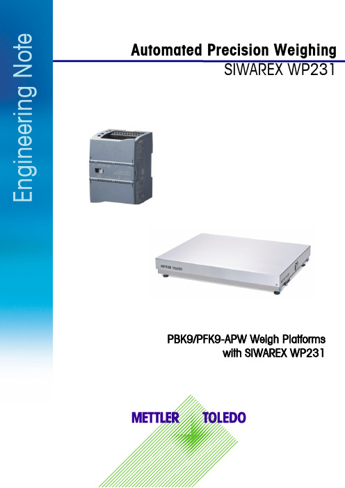
Automated Precision WeighingSIWAREX WP231E n g i n e e r i n g N o t ePBK9/PFK9-APW Weigh Platformswith SIWAREX WP2312E n g i n e e r i n g N o t eInhaltsverzeichnis1.1 Field of application ....................................................................................... 32.1 Connecting to Siwarex WP231 ...................................................................... 4 2.2 Configuring Siwarex WP231 ......................................................................... 5 2.3Configuring PBK9/PFK9 Weigh Platform ......................................................... 5 2.3.1 Connecting the weighing sensor to a PC ................................................................... 5 2.3.2 RS422/485 interface .............................................................................................. 5 2.3.3 Weight output ........................................................................................................ 6 2.3.4 User mode ............................................................................................................ 6 2.4 Weight transmission with Siwatool ................................................................. 6 4.1 Other Applicable Documents .......................................................................... 8 4.2 Figures . (8)1Introduction1.1Field of applicationPBK9/PFK9-APW weigh platforms from METTLER TOLEDO (hereafter referred to as “weighing sen-sors”)were developed especially for operation in automated plants. The weighing sensors profides an optionfor direct connection to the SIWAREX WP231 weighing system by Siemens (hereafter referred to as "Si-warex"). This document describes the steps for commissioning and optimizing this kind of connection.Figure 1: Connection to Siwarex via RS48534E n g i n e e r i n g N o t e2 CommissioningThis chapter summarizes, in form of a list, the steps required for commissioning PBK9/PFK9-APW weigh platforms at Siwarex.2.1 Connecting to Siwarex WP231The following diagram shows the connection of the PBK9/PFK9-APW weigh platforms to Siwarex WP231.Figure 2: Connection diagrammAssignment of the connections at SIWAREX WP231for the connection with PBK9/PFK9-APW weigh plat-form:2.2Configuring Siwarex WP231The following sections describe the steps required to configure the Siwarex when using Siwatool PCSoftware. Service mode must be activated before the records can be sent from Siwatool to the Siwarex:service commands-> Service Mode ON. When the service mode is activated, the corresponding icon(open-end wrench on red background) appears in the status bar.For SIWAREX WP231 as of firmware V3.0.4, parameters in the data record 3 and 13 must be adjustedas follows:DR3:Weight unit: grLoading cell type: Digital load cell Mettler Toledo PBKMaximum weight: capacity of the weighing sensor (unit: gr)Calibration weight 0: 0Calibration weight 1: capacity of the weighing sensor (unit: gr)Calibration weight 2: 0Calibration digits 0 (measured): 0Calibration digits 1 (measured): (capacity of the weighing sensor (unit: gr)) / (resolution)e.g.: 1 kg / 0.1 g = 1000 gr / 0.1 gr = 10,000Calibration digits 2 (measured): 0DR13:RS485 Protocol: Mettler Toledo PBK/PFK9 (Code 4)RS485 Baudrate: 38400RS485 Parity: evenRS485 Data Bits: 7RS485 Stop Bits: 1Delay: 2000 ms2.3Configuring PBK9/PFK9 Weigh PlatformThe steps are described below to configure the weighing sensor such that it operates with Siwarex.2.3.1Connecting the weighing sensor to a PCThe RS232 interface of the weighing sensor should be connected to a PC (using APW-Link TM - Free Con-figuration Tool – /apw-link) via the SubD9 connector of the ConBlock. The interface pa-rameters are configured in factory settings as follows: 9,600 baud, 8 data bits, no parity and1 stop bit.These settings shall NOT be modified.2.3.2RS422/485 interfaceFor the weighing platform, following parameters need to be configured:Parameter Value DescriptionM103 1 2 Configure the communication interface of the weighing platform as "RS485mode (half-duplex)"COM 1 8 0 0 Configure the communication interface of the weighing platform as follows:▪38400 bits per second▪7 data bits / even parity / 1 stop bit▪No handshakeM68 0 Keep the parameters of the communication interface permanently stored,such that they are not reset to factory defaults after a power cycle56E n g i n e e r i n g N o t e2.3.3 Weight outputFor seamless communication with the Siwarex, the update rate must be configured as follows:Update rate (UPD): UPD 922.3.4 User modeThe weighing sensors are automatically set to zero at power on. This might be undesirable in certain applications, particularly for larger platforms when a weight value shall be recovered after power off. When selecting the mode described below, the weight values refer to a fix reference point (as per pro-duction setting) and the zeroing at start up is disabled.Start-up with fix reference point: M35 12.4 Weight transmission with SiwatoolAfter successfully configuring the Siwarex and the weighing sensor, Siwatool can be used to weigh forcontrol purposes.The "Start Send" command (code 905) is used to send the individual records to the Siwarex. To con-firm, a record with “Receive” can be read out from the Siwarex. The communication can be stopped with the "Stop Send" command (code 906).Below in the picture, you can see the overview of the SIWATOOL:Figure 3: Siwatool(1) Control elements for SIWATOOL and the for the operation of the weighing sensor (2) Parameter list of the SIWATOOL module (3) Offline values of the SIWATOOL module(4) Online values of the connected SIWAREX module3Supported METTLER TOLEDO ProductsFTAV9.5.2WMS/WMSPBK9-APW/PBK9PFK9-APW/PFK9SLF6/SLF67Mettler-Toledo GmbH IndustrialCH-8606 Nänikon, SwitzerlandSubject to technical changes© 03/2017 Mettler-Toledo GmbHPrinted in Switzerland EN181_160407 4 Appendix4.1 Other Applicable Documents[1] METTLER TOLEDO, Reference Manual, Standard Interface Command Set (11781363G)[2] METTLER TOLEDO, Installation Manual PBK9 bench scales (30233012A)[3] METTLER TOLEDO, Installation Manual PFK9 floor scales (30233015A)[4]Siemens, Siwarex WP231, Device Manual, version 06/2014 (or later)4.2 FiguresFigure 1: Connection to Siwarex via RS485.................................. 3 Figure 2: Connection diagramm .................................................. 4 Figure 3: Siwatool (6)。
华为FusionSolar产品说明书

Battery Module (Energy Optimizer Included)
LUNA2000-5/10/15-S0
2.5
5
10
String Battery Solution
Power (kw)
DC Arc Fault Has Been Found the Major Cause of Fire in PV System
130GW+
Huawei inverters deployed worldwide
85% 100% 100% 100%
Higher Self-consumption
with Smart String ESS
Flexible
5kWh per pack scalable for flexible investment
Excellent product quality with extendable warranty to protect your investment
Standard 10 Years Warranty Extendable to Max. 20 Years
Available Now
FusionSolar Smart PV Management System
(Three Phase) SUN2000-3/4/5/6/8/10KTL-M1
Smart Energy Controller
Convert solar energy into electricity to power your house
Get FusionSolar with peace in mind
170+
Countries & regions with Huawei products and services
G1600-1500辊压机说明书
修改版号:
NCM809A-AM&SM
中材装备集团有限公司南京分公司
G1600-1500 辊压机 安装、使用说明书 NCM809A-AM&SM
编制 校对 审核 审定 共 1 册 / 复用 68 册
本册页数
2012 年 08 月 27 日
修改版号:
NCM809A-AM&SM
中材装备集团有限公司南京分公司
5. 出厂检验及运输 ............................................................................................... 16
5.1 随机文件 ............................................................................................................................................. 16 5.2 检测项目 ............................................................................................................................................. 16 5.3 运输 ..................................................................................................................................................... 17
西门子 NXGPro+ 控制系统手册_操作手册说明书
3.4
单元通讯的协议 ............................................................................................................ 36
3.5
NXGpro+ 高级安全 .......................................................................................................37
3.2
功率拓扑 ......................................................................................................................34
3.3
控制系统概述 ...............................................................................................................35
NXGPro+ 控制系统手册
NXGPro+ 控制系统手册
操作手册
AC
A5E50491925J
安全性信息
1
安全注意事项
2
控制系统简介
3
NXGPro+ 控制系统简介
4
硬件用户界面说明
5
参数配置/地址
6
运行控制系统
7
高级的操作功能
8
软件用户界面
9
运行软件
10
故障和报警检修
11
维沙尖 Siliconix S18-0633-Rev. A 汽车级 P-Channel 30 V 1
SQS407ENW-T1_GE3SQS407ENWVishay SiliconixAutomotive P-Channel 30 V (D-S) 175 °C MOSFETMarking code: Q033FEATURES•TrenchFET ® power MOSFET •AEC-Q101 qualified d •100 % R g and UIS tested•Material categorization:for definitions of compliance please see /doc?99912Notesa.Package limitedb.Pulse test; pulse width ≤ 300 μs, duty cycle ≤ 2 %c.When mounted on 1" square PCB (FR4 material)d.Parametric verification ongoinge.See solder profile (/doc?73257). The PowerPAK 1212-8W is a leadless package. The end of the lead terminal is exposed copper (not plated) as a result of the singulation process in manufacturing. A solder fillet at the exposed copper tip cannot be guaranteed and is not required to ensure adequate bottom side solder interconnectionf.Rework conditions: manual soldering with a soldering iron is not recommended for leadless componentsPRODUCT SUMMARYV DS (V)-30R DS(on) (Ω) at V GS = -10 V 0.0108R DS(on) (Ω) at V GS = -4.5 V 0.0170I D (A)-16Configuration SinglePackagePowerPAK 1212-8WPowerPAK ® 1212-8W S in g leTop View13.33.3mmm m Bottom View1S GD 8D D 6D S2S3475ABSOLUTE MAXIMUM RATINGS (T C = 25 °C, unless otherwise noted)PARAMETER SYMBOL LIMIT UNIT Drain-source voltage V DS-30VGate-source voltage V GS ± 20Continuous drain current aT C = 25 °C I D -16A T C = 125 °C-16Continuous source current (diode conduction) a I S -16Pulsed drain current bI DM -64Single pulse avalanche current L = 0.1 mH I AS -23Single pulse avalanche energy E AS 26.5mJ Maximum power dissipation bT C = 25 °C P D 62.5W T C = 125 °C 20Operating junction and storage temperature range T J , T stg-55 to +175°C Soldering recommendations (peak temperature) e, f260THERMAL RESISTANCE RATINGSPARAMETER SYMBOL LIMIT UNIT Junction-to-ambient PCB mount cR thJA 81°C/WJunction-to-case (drain)R thJC2.4SQS407ENWVishay SiliconixNotesa.Pulse test; pulse width ≤ 300 μs, duty cycle ≤ 2 %b.Guaranteed by design, not subject to production testingc.Independent of operating temperatureStresses beyond those listed under “Absolute Maximum Ratings” may cause permanent damage to the device. These are stress ratings only, and functional operation of the device at these or any other conditions beyond those indicated in the operational sections of the specifications is not implied. Exposure to absolute maximum rating conditions for extended periods may affect device reliability.SPECIFICATIONS (T C = 25 °C, unless otherwise noted)PARAMETER SYMBOL TEST CONDITIONS MIN.TYP.MAX.UNITStaticDrain-source breakdown voltage V DS V GS = 0 V, I D = -250 μA -30--V Gate-source threshold voltage V GS(th)V DS = V GS , I D = -250 μA -1.5-2.0-2.5Gate-source leakageI GSS V DS = 0 V, V GS = ± 20 V--± 100nAZero gate voltage drain current I DSS V GS = 0 V V DS = -30 V ---1μA V GS = 0 V V DS = -30 V, T J = 125 °C ---50V GS = 0 V V DS = -30 V, T J = 175 °C---150On-state drain current aI D(on)V GS = -10 V V DS ≤ -5 V -20--A Drain-source on-state resistance bR DS(on)V GS = -10 VI D = -12 A -0.00900.0108ΩV GS = -10 V I D = -12 A, T J = 125 °C --0.0150V GS = -10 V I D = -12 A, T J = 175 °C--0.0180V GS = -4.5 VI D = -9 A-0.01400.0170Forward transconductance b g fsV DS = -15 V, I D = -7 A-34-S Dynamic bInput capacitance C iss V GS = 0 VV DS = -20 V, f = 1 MHz-35154572pFOutput capacitanceC oss -376490Reverse transfer capacitance C rss -358465Total gate charge c Q g V GS = -10 VV DS = -15 V, I D = -4 A-5977nC Gate-source charge c Q gs -8.611.2Gate-drain charge c Q gd -11.515Gate resistance R g f = 1 MHz358ΩTurn-on delay time c t d(on)V DD = -15 V, R L = 3.8 ΩI D ≅ -4 A, V GEN = -10 V, R g = 1 Ω-11.415ns Rise time ct r -4 5.3Turn-off delay time c t d(off)-6281Fall time c t f -2432Source-Drain Diode Ratings and Characteristics bPulsed current a I SM ---64A Forward voltageV SDI F = -8.8 A, V GS = 0 V --0.8-1.2VSQS407ENW Vishay SiliconixTYPICAL CHARACTERISTICS(T A = 25 °C, unless otherwise noted)Output Characteristics TransconductanceCapacitanceTransfer CharacteristicsOn-Resistance vs. Drain CurrentGate ChargeSQS407ENWVishay SiliconixTYPICAL CHARACTERISTICS (T A = 25 °C, unless otherwise noted)On-Resistance vs. Junction Temperature On-Resistance vs. Gate-to-Source Voltage Source Drain Diode Forward VoltageThreshold VoltageDrain Source Breakdown vs. Junction TemperatureSQS407ENW Vishay SiliconixTHERMAL RATINGS(T A = 25 °C, unless otherwise noted)Safe Operating AreaNormalized Thermal Transient Impedance, Junction-to-AmbientSQS407ENW Vishay SiliconixTHERMAL RATINGS(T A = 25 °C, unless otherwise noted)Normalized Thermal Transient Impedance, Junction-to-CaseNote•The characteristics shown in the two graphs- Normalized Transient Thermal Impedance Junction-to-Ambient (25 °C)- Normalized Transient Thermal Impedance Junction-to-Case (25 °C)are given for general guidelines only to enable the user to get a “ball park” indication of part capabilities. The data are extracted from single pulse transient thermal impedance characteristics which are developed from empirical measurements. The latter is valid for the part mounted on printed circuit board - FR4, size 1" x 1" x 0.062", double sided with 2 oz. copper, 100 % on both sides. The part capabilities can widely vary depending on actual application parameters and operating conditionsVishay Silicon ix main tain s worldwide man ufacturin g capability. Products may be man ufactured at on e of several qualified location s. Reliability data for Silicon Technology and Package Reliability represent a composite of all qualified locations. For related documents such as package / tape drawings, part marking, and reliability data, see /ppg?76627.Package Information Vishay SiliconixPowerPAK® 1212-8W Case OutlineDIM.MILLIMETERS INCHESMIN.NOM.MAX.MIN.NOM.MAX.A0.97 1.04 1.120.0380.0410.044 A10-0.050-0.002 A20-0.130-0.005 b0.230.300.410.0090.0120.016 c0.230.280.330.0090.0110.013D 3.20 3.30 3.400.1260.1300.134D1 2.95 3.05 3.150.1160.1200.124 D2 1.98 2.11 2.240.0780.0830.088 D40.47 typ.0.0185 typ.D5 2.3 typ.0.090 typ.E 3.20 3.30 3.400.1260.1300.134E1 2.95 3.05 3.150.1160.1200.124 E2 1.47 1.60 1.730.0580.0630.068 E3 1.75 1.85 1.980.0690.0730.078 E40.34 typ.0.013 typ.e0.65 BSC.0.026 BSCK0.86 typ.0.034 typ.H0.300.410.510.0120.0160.020 L0.300.430.560.0120.0170.022 L10.060.130.200.0020.0050.008 0°-12°0°-12°W0.150.250.360.0060.0100.014 M0.125 typ.0.005 typ.ECN: C15-1530-Rev. B, 16-Nov-15DWG: 6032Application Note 826Vishay SiliconixA P P L I C A T I O N N O T RECOMMENDED MINIMUM PADS FOR PowerPAK ® 1212-8 SingleLegal Disclaimer Notice VishayDisclaimerALL PRODUCT, PRODUCT SPECIFICAT IONS AND DAT A ARE SUBJECT T O CHANGE WIT HOUT NOT ICE T O IMPROVE RELIABILITY, FUNCTION OR DESIGN OR OTHERWISE.Vishay Intertechnology, Inc., its affiliates, agents, and employees, and all persons acting on its or their behalf (collectively, “Vishay”), disclaim any and all liability for any errors, inaccuracies or incompleteness contained in any datasheet or in any other disclosure relating to any product.Vishay makes no warranty, representation or guarantee regarding the suitability of the products for any particular purpose or the continuing production of any product. To the maximum extent permitted by applicable law, Vishay disclaims (i) any and all liability arising out of the application or use of any product, (ii) any and all liability, including without limitation special, consequential or incidental damages, and (iii) any and all implied warranties, including warranties of fitness for particular purpose, non-infringement and merchantability.Statements regarding the suitability of products for certain types of applications are based on Vishay’s knowledge of typical requirements that are often placed on Vishay products in generic applications. Such statements are not binding statements about the suitability of products for a particular application. It is the customer’s responsibility to validate that a particular product with the properties described in the product specification is suitable for use in a particular application. Parameters provided in datasheets and / or specifications may vary in different applications and performance may vary over time. All operating parameters, including typical parameters, must be validated for each customer application by the customer’s technical experts. Product specifications do not expand or otherwise modify Vishay’s terms and conditions of purchase, including but not limited to the warranty expressed therein.Except as expressly indicated in writing, Vishay products are not designed for use in medical, life-saving, or life-sustaining applications or for any other application in which the failure of the Vishay product could result in personal injury or death. Customers using or selling Vishay products not expressly indicated for use in such applications do so at their own risk. Please contact authorized Vishay personnel to obtain written terms and conditions regarding products designed for such applications.No license, express or implied, by estoppel or otherwise, to any intellectual property rights is granted by this document or by any conduct of Vishay. Product names and markings noted herein may be trademarks of their respective owners.© 2017 VISHAY INTERTECHNOLOGY, INC. ALL RIGHTS RESERVEDSQS407ENW-T1_GE3。
永磁直线伺服系统终端互补滑模位置控制
第27卷㊀第6期2023年6月㊀电㊀机㊀与㊀控㊀制㊀学㊀报Electri c ㊀Machines ㊀and ㊀Control㊀Vol.27No.6Jun.2023㊀㊀㊀㊀㊀㊀永磁直线伺服系统终端互补滑模位置控制赵希梅,㊀孙洪潇,㊀金鸿雁(沈阳工业大学电气工程学院,辽宁沈阳110870)摘㊀要:为了解决永磁直线同步电机(PMLSM )直驱伺服系统易受端部效应㊁非线性摩擦以及外部扰动等不确定因素影响的问题,提出一种将互补滑模控制(CSMC )与终端滑模控制(TSMC )相结合的终端互补滑模控制(TCSMC )方法㊂首先,建立具有不确定因素的PMLSM 动态模型㊂其次,将广义滑模面与互补滑模面相结合,同时利用饱和函数替换切换函数设计CSMC ,与传统的滑模控制相比,其跟踪误差减半,能有效削弱抖振㊂为了进一步提高系统的收敛速度,在互补滑模面中引入终端项,设计TCSMC ,使得系统在CMSC 减少系统误差的基础上,进一步提高控制性能㊂最后,通过理论分析,证明控制器的稳定性,系统实验表明,与CSMC 和TSMC 相比,TCSMC 不但提高了系统收敛速度和控制精度,削弱了抖振现象,而且明显增强了系统的鲁棒性㊂关键词:永磁直线同步电机;不确定因素;终端互补滑模控制器;收敛速度;控制精度;鲁棒性DOI :10.15938/j.emc.2023.06.019中图分类号:TP273文献标志码:A文章编号:1007-449X(2023)06-0182-09㊀㊀㊀㊀㊀㊀㊀㊀㊀㊀㊀㊀㊀㊀㊀㊀㊀㊀㊀㊀㊀㊀㊀㊀㊀㊀㊀㊀㊀㊀㊀㊀㊀㊀㊀㊀㊀㊀㊀㊀㊀㊀㊀㊀㊀㊀㊀㊀㊀㊀㊀㊀㊀㊀㊀㊀㊀㊀㊀㊀㊀㊀㊀㊀㊀㊀㊀㊀㊀㊀㊀㊀㊀㊀㊀㊀㊀㊀㊀㊀㊀㊀㊀㊀㊀㊀㊀㊀㊀㊀㊀㊀㊀㊀㊀㊀㊀㊀㊀㊀㊀㊀㊀㊀㊀㊀㊀㊀㊀㊀收稿日期:2022-05-10基金项目:辽宁省博士科研启动基金计划项目(2022-BS -177)作者简介:赵希梅(1979 ),女,博士,教授,博士生导师,研究方向为电机控制㊁智能控制;孙洪潇(1998 ),女,硕士研究生,研究方向为直线电机及其控制;金鸿雁(1993 ),女,博士,讲师,研究方向为电机控制㊁智能控制㊂通信作者:赵希梅Terminal complementary sliding mode position control forpermanent magnet linear servo systemZHAO Ximei,㊀SUN Hongxiao,㊀JIN Hongyan(School of Electrical Engineering,Shenyang University of Technology,Shenyang 110870,China)Abstract :In order to solve the problem that permanent magnet linear synchronous motor (PMLSM)direct drive servo system is susceptible to end effect,nonlinear friction and external disturbance,a terminal complementary sliding mode control (TCSMC)method combining complementary sliding mode control (CSMC)and terminal sliding mode control (TSMC)is proposed.Firstly,a PMLSM dynamic model with uncertain factors was established.Secondly,the CSMC was designed by combining the generalized sliding mode surface with the complementary sliding mode surface,and replacing the switching function with the saturation function.The tracking error is half of the traditional sliding mode control,which can effectively reduce chattering.In order to further improve the convergence speed of the system,a terminal term was introduced into the complementary sliding mode surface and TCSMC was designed,which can further im-prove the control performance of the system while reducing system errors by CMSC.Finally,through the-oretical analysis,the stability of the controller was demonstrated.System experiments show that compared with CSMC and TSMC,TCSMC can improve the system convergence speed and control accuracy,weakenthe chattering phenomenon,and significantly enhance the system robustness.Keywords:permanent magnet linear synchronous motor;uncertainty;terminal complementary sliding mode controller;convergence speed;control accuracy;robustness0㊀引㊀言近年来,永磁直线同步电机(permanent magnet linear synchronous motor,PMLSM)由于具有精度高㊁推力大㊁速度快的优势,被广泛应用于医疗器械㊁定位平台和航空航天等许多工业应用中的精密定位领域[1-2]㊂由于省去了传统旋转电机结构中间的机械传动装置,有效减小了机械损耗,增大了电磁推力,但同时端部效应㊁摩擦力以及外部扰动等不确定因素直接作用于动子上,会对PMLSM造成不利影响[3-4],给控制带来困难㊂因此,改进实际控制方法对促进PMLSM在高精度伺服领域的发展有十分重大的意义㊂针对高精度㊁快响应的运动要求,学者们提出许多不同的控制方法,如无差拍电流预测控制[5]㊁反推控制[6]㊁自适应神经网络鲁棒控制[7]㊁迭代学习控制[8]以及滑模控制(sliding mode control,SMC)[9]等㊂在上述方法中,SMC因响应快㊁对不确定因素不敏感㊁易于实现等优势,引起学者们的广泛关注[10]㊂但是SMC也有固有的缺点,即滑模面设计中的大切换控制增益会引起系统的高频抖振问题㊂文献[11]将全阶SMC应用于高阶非线性系统中,削弱了系统抖振,但控制器设计较为复杂,引入赫尔维茨多项式,且需进行多次求导㊂文献[12]设计了一种积分终端滑模面,积分与TSMC相结合,有效减小了抖振并提高了鲁棒性,但是将符号函数引入滑模控制率,使得系统的稳定性得不到保证㊂文献[13]将模糊控制与分数阶SMC相结合,减小了稳态误差和调节时间,但模糊规则不易选取㊂互补滑模控制(complementary sliding mode con-trol,CSMC)较好地解决了SMC中固有的抖振问题,滑模面中结合了广义滑模面与互补滑模面,能够有效增强系统鲁棒性,使系统的跟踪误差减小,提高了跟踪性能㊂文献[14]设计CSMC减小了PMLSM伺服系统受不确定因素的影响,与SMC相比,其位置跟踪误差减半,有效改善了位置跟踪性能,提高了鲁棒性,但其在误差减小时收敛速度较慢㊂文献[15]提出CSMC中优化饱和函数边界层厚度参数方法,获得了边界层参数的最优值,有效抑制了抖振,但瞬态响应并未有所提高㊂文献[16]提出一种非线性系统的非奇异终端滑模控制方法(terminal sliding mode controller,TSMC),保证了系统在有限时间内收敛,提高了跟踪性能,但系统对于外部扰动非常敏感,甚至在扰动较大时会发生系统失稳的现象㊂将CSMC跟踪误差小㊁鲁棒性强的优点与TSMC在误差减小时收敛速度快的优势相结合,在互补滑模面中引入终端项,提出一种PMLSM终端互补滑模控制(terminal complementary sliding mode control,TCSMC)方法㊂首先,利用CSMC策略提高系统的控制精度和鲁棒性㊁削弱抖振;然后,结合TSMC收敛速度快的优势,进一步提高系统的跟踪性能㊂实验证明,该控制方法可以有效提高系统的控制精度,增强系统的鲁棒性,降低系统的跟踪误差,削弱系统抖振,提高系统的收敛速度和跟踪性能㊂1㊀PMLSM数学模型首先,对PMLSM采用矢量控制,可得电磁推力为F e=3π2τp[ψf i q+(L d-L q)i d i q]㊂(1)式中:i d㊁i q分别为d㊁q轴电流;p为极对数;τ为极距;ψf为永磁体产生的励磁磁链;L d㊁L q分别为d㊁q 轴励磁电感㊂由于PMLSM气隙较大,所以可以忽略磁极的凸极效应和电机的电枢反应,即L d=L q㊂另外,令电流内环i d=0,可得到PMLSM的电磁推力方程为F e=3π2τpψf i q=K f i q㊂(2)式中K f为电磁推力系数,K f=3π2τpψf㊂PMLSM的机械运动方程可表示为F e=M d v d t+B v v+FΣ㊂(3)式中:M为动子和动子所带负载的总质量;v为动子速度;B v为粘滞摩擦系数;FΣ为集总扰动,包括端部效应波动推力F end㊁摩擦力F fri以及其他系统不确定性扰动㊂其中:F end=F emax cos2πdτ();(4)381第6期赵希梅等:永磁直线伺服系统终端互补滑模位置控制F fri =(F s -F c )e -(d ㊃/v s )2sgn(d ㊃)+F c sgn(d ㊃)㊂(5)式中:F emax 为推力波动峰值;d 为动子位移;F s 为最大静摩擦力;F c 为最小库仑摩擦力;d ㊃为动子速度;v s 为Stribeck 速度系数;sgn(㊃)为符号函数㊂忽略集总扰动F Σ对系统的影响,由式(2)㊁式(3)可得d v d t =d ㊃㊃=-B v M v +K f Mi q =A n d ㊃+B n u ㊂(6)式中:u =i q ,为控制器输入;A n =-B v /M ;B n =K f /M ,为系统标态下的参数㊂存在不确定性影响时,将式(6)改写为d ㊃㊃=(A n +ΔA )d ㊃+(B n +ΔB )u +(C n +ΔC )F Σ=A n d ㊃+B n u +H ㊂(7)式中:ΔA n ㊁ΔB n 和ΔC 为系统参数M ㊁B v 受扰动后发生变化引起的参数变化量;C n =-1/M ;H 为系统的总不确定因素,表达式为H =ΔAd ㊃+ΔBu +(C n +ΔC )F Σ,(8)且假设系统集总扰动有界,则|H |也有界,即|H |ɤρ,ρ为正常数㊂2㊀PMLSM 系统设计2.1㊀PMLSM 系统组成PMLSM 伺服控制系统框图如图1所示㊂系统外环位置环中控制器采用TCSMC,同时采用CSMC㊁TSMC 进行对比实验,输入为位置跟踪误差,输出为q 轴电流指令信号,内环电流环中控制器采用PI 控制㊂图1㊀PMLSM 控制系统框图Fig.1㊀Block diagram of PMLSM servo control system2.2㊀互补滑模控制器设计为保证PMLSM 伺服系统的控制性能,减小不确定性的影响,提高电机运行时的位置跟踪精度,采用CSMC 减少位置跟踪误差,提高系统的跟踪性能和鲁棒性,削弱传统滑模控制策略的抖振现象㊂CSMC 结构框图如图2所示㊂图2㊀CSMC 结构图Fig.2㊀Structure diagram of CSMC为实现动子的实际位置d 精准地跟踪给定位置d m ,定义跟踪误差为e =d m -d ㊂(9)设计广义滑模面s g1和互补滑模面s c1分别为:s g1=(dd t +λ1)2ʏt0e (τ)d τ=e ㊃+2λ1e +λ21ʏt 0e (τ)d τ;(10)s c1=(d d t +λ1)(dd t -λ1)ʏte (τ)d τ=e ㊃-λ21ʏte (τ)d τ㊂(11)式中λ1为正常数㊂由式(10)㊁式(11)可得滑模面间关系为s㊃c1+λ1(s g1+s c1)=s ㊃g1㊂(12)为保证系统的稳定性,设计互补滑模控制律为:u CSMC =u eq1+u v1;(13)u eq1=1B n[d ㊃㊃m -A n d ㊃+λ1(2e ㊃+λ1e +s g1)];(14)u v1=1B n ρ1sat s c1+s g1Φ1()[]㊂(15)式中:u eq1为等效控制律;u v1为切换控制律;ρ1为给定正常数;Φ1为边界层厚度;sat(㊃)为饱和函数,表达式为satsg1+s c1Φ1()=1,s g1+s c1ȡΦ1;s g1+s c1Φ1,-Φ1<s g1+s c1<Φ1;-1,s g1+s c1ɤ-Φ1㊂ìîíïïïï(16)481电㊀机㊀与㊀控㊀制㊀学㊀报㊀㊀㊀㊀㊀㊀㊀㊀㊀㊀㊀㊀㊀第27卷㊀其最终边界可以限定为:|e |ɤΦ12λ1;|e ㊃|ɤΦ1㊂üþýïïï(17)误差会在有限时间内收敛至边界层,然后沿着滑模面向零点的邻域滑动,与传统SMC 相比,跟踪误差减半,但是,其收敛时间并没有进一步减少,而TSMC 可以有效缩短收敛时间㊂2.3㊀终端滑模控制器设计设计终端滑模面为s =e ㊃+αe κ1/κ2㊂(18)式中:α>0;κ2>κ1>0,且κ1㊁κ2均为奇数㊂设计控制率为:㊀㊀u TSMC =u 1+u 2;(19)㊀㊀u 1=1B n d ㊃㊃m -A n d ㊃+ακ1κ2e ㊃e κ1-κ2κ2();(20)㊀㊀u 2=1B n ρ2sat(s )㊂(21)式中:u 1为等效控制项,用于控制系统的确定部分;u 2为非线性控制项,用于控制系统的不确定部分;ρ2为正常数㊂假设,t =0时,终端滑模面s (0)ʂ0,t r 为从s (0)到s =0的时间,即s (t r )=0㊂因为ss ㊃ɤ-γ1|s |,γ1为ρ2和扰动之间的差值,设s (0)ȡ0,则s ㊃ɤ-γ1,两边积分得ʏs (t r )s (0)d s ɤʏt r-λ1d t ㊂(22)可得t r ɤs (0)γ1,同理,当s (0)ɤ0时,t r ɤ-s (0)γ1,即系统在任意状态到达滑模面的时间t r ɤ|s (0)|γ1㊂到达滑模面s =0后,s =e ㊃+αe κ1/κ2=0,则由d ed t=-αe κ1/κ2可求得κ2κ2-κ1e (t r )κ2-κ1κ2=αΔt ㊂(23)即系统由滑模面到达原点的时间为Δt =κ2α(κ2-κ1)e (t r )κ2-κ1κ2㊂(24)所以可得,系统经t r +Δt 由任意状态到达原点㊂与传统SMC 的渐近收敛相比,明显提高了收敛速度㊂2.4㊀终端互补滑模控制器设计与传统的SMC 相比,CSMC 可以有效地减少系统跟踪误差,提高系统跟踪性能㊂但与TSMC 系统可以在t r +Δt 时间段内由任意状态到达原点相比,在误差减小时,CSMC 收敛速度变慢㊂因此,将CSMC 思想和TSMC 相结合,设计了TCSMC,以提高系统的控制性能,其结构框图如图3所示㊂图3㊀TCSMC 系统结构图Fig.3㊀System structure diagram of TCSMCTCSMC 设计如下,将终端项引入滑模面可得广义滑模面s g2和互补滑模面s c2分别为:s g2=e ㊃+2λ2e +λ2e m+λ22ʏt 0[e (τ)+e m(τ)]d τ;(25)s c2=e ㊃+λ2e m -λ22ʏt[e (τ)+e m(τ)]d τ㊂(26)式中m 为一正常数,0<m =ab<1,a ㊁b 均为正奇数㊂根据s g2和s c2得到滑模面总和σ,表达式为σ=s g2+s c2=2e ㊃+2λ2(e m +e )㊂(27)由式(19)㊁式(20)可得:s㊃g2=e ㊃㊃+2λ2e ㊃+λ2me m-1e ㊃+λ22(em+e )=(d ㊃㊃m -A n d ㊃-B n u -H )+2λ2e ㊃+λ2me m-1e ㊃+λ22(em+e );(28)s㊃c2=e ㊃㊃+λ2me m-1e ㊃-λ22(em +e )=(d ㊃㊃m -A n d ㊃-B n u -H )+λ2me m-1e ㊃-λ22(em+e )㊂(29)确定s g2和s c2的关系为s㊃c2+λ2σ=s ㊃g2㊂(30)选择Lyapunov 函数V 为V =12(s 2g2+s 2c2)㊂(31)对V 求导可以得到581第6期赵希梅等:永磁直线伺服系统终端互补滑模位置控制V ㊃=s g2s ㊃g2+s c2s ㊃c2=(s g2+s c2)[d ㊃㊃m -A n d ㊃-B n u -H +2λ2e ㊃+λ2me m-1e ㊃+λ22(e +e m )-λ2s c2]㊂(32)因此,得到终端互补滑模控制律u TCSMC ,表达式为:u TCSMC =u eq2+u v2;(33)u eq2=1B n{d ㊃㊃m -A n d ㊃+λ2[2e ㊃+me m-1e ㊃+λ2(e +e m )+s g2]};(34)u v2=1B n ρ3sat σΦ2()[]㊂(35)结合式(26)~式(29)可得㊀V ㊃=s g2s ㊃g2+s c2s ㊃c2=-λ2(s g2+s c2)2+(s g2+s c2)(-B n u v2)+(s g2+s c2)(-H )ɤ-λ2(s g2+s c2)2+(s g2+s c2)(-B n u v2)+|s g2+s c2||-H |ɤ-λ2(s g2+s c2)2+|s g2+s c2|(|H |-ρ3)㊂(36)由ρ3为H 的上界可得V ㊃ɤ0,即系统满足Lya-punov 稳定性条件,滑模运动可在有限时间内到达边界层㊂假设t =0时,滑模面总和σ(0)ʂ0,t ᶄr 为从σ(0)到σ=0的时间,即σ(t ᶄr )=0㊂因为σσ㊃ɤ-2γ2|σ|,γ2为ρ3和扰动之间的差值,设σ(0)ȡ0,则σ㊃ɤ-2γ2,两边积分得ʏσ(t ᶄr )σ(0)d σɤʏt ᶄr-2γ2d t ,(37)可得t ᶄr ɤσ(0)2γ2,同理,当s (0)ɤ0时,t ᶄr ɤ-σ(0)2γ2,即系统在任意状态到达滑模面的时间t ᶄrɤ|σ(0)|2γ2㊂到达滑模面σ=0后,σ=2e ㊃+2λ2(e m +e )=0,即d ed t=-λ2(e m +e ),即ʏt ᶄr +Δtᶄt ᶄr1e m+ed e =-λ2Δt ᶄ㊂(38)与TSMC 相似,此处不再赘述,TCSMC 也可经有限时间,即Δt ᶄ时间段由滑模面收敛到原点㊂所以可得,系统经t ᶄr +Δt ᶄ由任意状态到达原点,与互补滑模的渐进收敛相比,明显提高了收敛速度㊂3㊀系统实验分析为验证TCSMC 方法的有效性,基于Links-RT实验平台分别对采用CSMC㊁TSMC 和TCSMC 3种方法的PMLSM 伺服系统进行实验研究,实验框图如图4所示㊂Links-RT 半实物仿真平台可以将数学仿真和物理实验相结合,为系统提供一个半物理的实验环境㊂采用上-下机位的系统架构,上位机中进行模型搭建㊁系统试验㊁编译生成二进制代码以及试验后的数据处理等工作,下机位运行在VxWorks 操作系统上,对模型实时解算并进行数据采集及传输㊂其中通过调节 通用型伺服驱动器 的控制模式,改变负载电机的推力,从而以对拖的形式模拟实验电机的负载变化情况㊂图4㊀基于Links-RT 的PMLSM 实验系统框图Fig.4㊀Block diagram of experiment for PMLSM sys-tem based on Links-RT实验中所选PMLSM 参数为:极距τ=32mm,极对数n p =2,动子绕组电阻R s =2.5Ω,d㊁q 轴电感L d =L q =8.2mH,磁通ψf =0.09Wb,M =8.2kg,K f =50.7N /A,B =0.01N㊃s /m㊂为使系统工作在最佳状态,通过试凑法不断调试得到控制器相关参数㊂CSMC 的参数为:Φ1=0.01,ρ1=5,λ1=400;TSMC 的参数为:α=300,κ1=5,κ2=3,ρ2=500;TC-SMC 的参数为:λ2=50,Φ2=0.0045,a =23,b =25,ρ3=650㊂给系统3种不同的输入信号:1)幅值为1mm的阶跃信号,在0.2s 时负载由F L =100N 增加到F L =400N;2)幅值为1mm 的阶跃信号,在0.2s 时负载由F L =500N 减为F L =200N;3)幅值为1mm,频律为25Hz 的正弦信号,全程加入随机扰动,且在0.3s 时负载由5N 增加到20N㊂实验一:图5(a)是系统输入信号为1)时,基于CSMC㊁TSMC 和TCSMC 的位置跟踪曲线,其误差曲线如图5(b)所示㊂681电㊀机㊀与㊀控㊀制㊀学㊀报㊀㊀㊀㊀㊀㊀㊀㊀㊀㊀㊀㊀㊀第27卷㊀图5㊀输入信号1)下的位置曲线对比图Fig.5㊀Comparison charts of the position curves under the input signal1)启动时,TCSMC系统在0.04s便达到了稳定状态,稳态误差为0.7μm;TSMC系统稳定时间为0.02s,稳态误差为1.6μm;而CSMC系统启动超调量为0.8mm,稳定用时0.08s,稳态误差为0.1μm㊂0.2s突增负载扰动时,TCSMC系统最大误差为10μm,在0.025s后重新恢复到稳定状态,稳态误差为2.5μm㊂CMSC系统最大误差为0.33mm,在0.06s后重新恢复到稳定状态,稳态误差为0.14μm㊂而TSMC系统最大误差为32μm,在0.008s后恢复到稳定状态,误差为17μm㊂另外,由图可知,TCSMC明显削弱系统的抖振现象,在0.2s前的稳定状态,TCSMC系统抖振幅度为20nm,TSMC系统和CSMC分别为0.2μm和0.25μm;突增负载扰动稳定后,TCSMC系统抖振幅度为13nm,TSMC系统和CSMC系统分别为23nm㊁0.15μm㊂表1为输入信号为1)时各控制器跟踪性能的比较,其中:δ1为启动时超调量,t1为启动时间,δ2为启动时的稳态误差,δ3为F L=100N时的抖振幅度,δ4为突增负载扰动时系统的最大误差,t2为恢复稳定时间,δ5为突增负载扰动后的稳态误差,δ6为F L=400N时的抖振幅度㊂表1㊀输入信号为1)时各控制器跟踪性能比较Table1㊀Comparison of tracking performance for each controller when the input signal is1)参数CSMC TSMC TCSMCδ1/mm0.8t1/s0.080.020.04δ2/μm0.1 1.60.7δ30.25μm0.2μm20nmδ40.33mm32μm10μmt2/s0.060.0080.025δ5/μm0.1417 2.5δ60.15μm23nm13nm实验二:图6(a)是系统输入信号为2)时,基于CSMC㊁TSMC和TCSMC的位置跟踪曲线,其误差曲线如图6(b)所示㊂图6㊀输入信号2)下的位置曲线对比图Fig.6㊀Comparison chart of the position curves under the input signal2)启动时由于负载影响,TSMC㊁CSMC系统的最大误差均为0.14mm,TCSMC系统最大误差为0.06mm㊂TSMC系统0.03s到达稳定状态,稳态误差为24μm;CSMC系统超调量为1.02mm,0.08s 到达稳定状态,稳态误差为0.25μm;TCSMC系统0.05s到达稳定状态,稳态误差为3.4μm㊂0.2s 突减负载时,TCSMC系统最大误差为9μm,在0.03s 后重新恢复到稳定状态,稳态误差为0.7μm㊂CM-781第6期赵希梅等:永磁直线伺服系统终端互补滑模位置控制SC系统最大误差为0.32mm,在0.06s后重新恢复到稳定状态,稳态误差为0.13μm㊂TSMC系统则由上一次的稳态向这一次稳态过渡,误差由24μm逐渐减小,0.01s后恢复到稳定状态,稳态误差为5.3μm㊂在0.2s前的稳定状态,TCSMC系统抖振宽度为20nm,TSMC系统和CSMC系统分别为30nm和0.12μm㊂突减负载扰动稳定后,TCSMC 系统抖振宽度为20nm,TSMC系统和CSMC系统分别为30nm㊁0.15μm㊂表2为输入信号为2)时各控制器跟踪性能的比较,其中:δ7为系统启动最大误差,δ8为启动超调量,t3为启动时间,δ9为F L=500N时稳态误差,δ10为其抖振宽度,δ11为突减负载扰动时系统的最大误差,t4为恢复稳定时间,δ12为F L=200N的稳态误差㊂表2㊀输入信号为2)时各控制器跟踪性能比较Table2㊀Comparison of tracking performance for each controller when the input signal is2)参数CSMC TSMC TCSMCδ7/mm0.140.140.06δ8/mm 1.02t3/s0.080.030.05δ9/μm0.2524 3.4δ100.12μm30nm20nmδ110.32mm 9μmt4/s0.060.010.03δ12/μm0.13 5.30.7由表1和表2可知,TCSMC系统较CSMC系统响应速度明显提高,有效减小了瞬态误差;而与TSMC系统相比,带负载情况下,稳态误差更小,且受负载扰动影响更小,具有更好的跟踪性和鲁棒性㊂另外,TCSMC系统能更好地抑制系统抖振㊂实验三:图7(a)为给定的随机外界扰动,图7(b)为系统输入信号为3)时,基于CSMC㊁TSMC 和TCSMC的位置跟踪曲线,图7(c)~图7(d)是其误差曲线㊂启动时,TCSMC超调量为7μm,稳定时间为15ms,稳定误差受随机扰动的影响,在-37nm~0.1μm范围内呈波动状态,0.3s突加负载扰动后,误差在0.3~0.5μm范围内波动,抖振幅度为20nm;TSMC系统启动无超调,稳定时间为9ms,稳定误差波动范围为8nm~0.15μm,0.3s 突加负载扰动后,误差在0.4~0.8μm范围内波动,抖振幅度为30nm;而CSMC系统启动超调量为10μm,稳定时间为24ms,稳定误差在随机扰动的影响下在-19~96nm范围内波动,0.3s突加负载扰动后,误差在0.22~0.35μm范围内波动,抖振幅度为25nm㊂图7㊀输入信号3)下的位置曲线对比图Fig.7㊀Comparison charts of the position curves under the input signal3)表3为输入信号为3)时,各控制器跟踪性能的比较,其中:δ13为启动时的超调量,t5为启动时间,881电㊀机㊀与㊀控㊀制㊀学㊀报㊀㊀㊀㊀㊀㊀㊀㊀㊀㊀㊀㊀㊀第27卷㊀δ14为只有随机扰动时的稳态误差,δ15为突增负载扰动后的稳态误差,δ16为抖振幅度㊂表3㊀输入信号为3)时各控制器跟踪性能比较Table3㊀Comparison of tracking performance for each controller when the input signal is3)参数CSMC TSMC TCSMCδ13/μm10 7t5/ms24915δ14-19~96nm8nm~0.15μm-37nm~0.1μm δ15/μm0.2~0.350.4~0.80.3~0.5δ16/nm253020由表可知,在起始阶段,TCSMC系统与CSMC 系统比较,在引入终端项的影响下,明显提高了系统的响应速度,减小了超调量;而与TSMC系统比较,在互补滑模面的影响下,减少了稳态误差,对负载扰动具有更强的鲁棒性㊂在负载扰动前后的稳定状态下,TCSMC系统明显比CSMC系统和TSMC系统的抖振幅度更小,即有效地抑制了抖振现象㊂4㊀结㊀论为满足PMLSM伺服系统高跟踪性能的加工要求,减小不确定因素对精度的影响,提高系统的鲁棒性,设计了一种将CSMC思想与TSMC相结合的控制方法㊂首先利用CSMC削弱传统滑模控制中存在的抖振问题,增强系统鲁棒性,提高系统的控制精度;然后在互补滑模面中引入终端项,提高系统的收敛速度,使TCSMC不仅具有CSMC跟踪误差减半的优势,而且具有TSMC在误差减小时收敛速度快的优点㊂实验结果表明,该方法不仅能够提高系统跟踪精度和收敛速度,增强系统鲁棒性,而且明显减小了系统的抖振幅度㊂参考文献:[1]㊀LIU Xiaoli,ZHEN Shengchao,SUN Hao,et al.A novel modelbased robust control for position tracking of permanent magnet line-ar motor[J].IEEE Transactions on Industrial Electronics,2020, 67(9):7767.[2]㊀HU C,OU H C.Deep GRU neural-network prediction and feed-forward compensation for precision multi-axis motion control sys-tems[J].IEEE/ASME Transactions on Mechatronics,2020,25(3):1377.[3]㊀张康,王丽梅.基于周期性扰动学习的永磁直线电机自适应滑模位置控制[J].电机与控制学报,2021,25(8):132.ZHANG Kang,WANG Limei.Adaptive sliding mode position con-trol for permanent magnet linear motor based on periodic disturb-ance learning[J].Electric Machines and Control,2021,25(8):132.[4]㊀HUANG Xuzhen,LI Jing,TAN Qiang,et al.Sectional combina-tions of the modular tubular permanent magnet linear motor and the optimization design[J].IEEE Transactions on Industrial Electron-ics,2018,65(12):9658.[5]㊀尹忠刚,白聪,杜超,等.基于内模干扰观测器的永磁同步直线电机无差拍电流预测控制方法[J].电工技术学报,2018,33(24):5741.YIN Zhonggang,BAI Cong,DU Chao,et al.Deadbeat predictive current control for permanent magnet linear synchronous motor based on internal model disturbance observer[J].Transactions of China Electrotechnical Society,2018,33(24):5741. [6]㊀赵希梅,王天鹤.基于Hermite多项式函数链模糊神经网络的PMLSM分数阶反推控制[J].电机与控制学报,2021,25(9):61.ZHAO Ximei,WANG Tianhe.Fractional-order backstepping con-trol based on Hermite polynomial functional link fuzzy neural net-work for PMLSM[J].Electric Machines and Control,2021,25(9):61.[7]㊀王一光,李晓杰,陈兴林.基于永磁直线同步电机的光刻机掩模台鲁棒自适应神经网络控制[J].电工技术学报,2016,31(6):38.WANG Yiguang,LI Xiaojie,CHEN Xinglin.A robust adaptive neural network control method based on permanent magnetic linear synchronous motor for the reticle stage of lithography[J].Transac-tions of China Electrotechnical Society,2016,31(6):38. [8]㊀SONG Fazhi,LIU Yang,XU Jianxin,et al.Iterative learning i-dentification and compensation of space-periodic disturbance in PMLSM systems with time delay[J].IEEE Transactions on Indus-trial Electronics,2018,65(9):7579.[9]㊀孙宜标,仲原,刘春芳,基于LMI的直线伺服滑模位移跟踪控制[J].电工技术学报,2019,34(1):33.SUN Yibiao,ZHONG Yuan,LIU Chunfang.LMI-based sliding mode displacement tracking control for permanent magnet linear synchronous motor[J].Transactions of China Electrotechnical So-ciety,2019,34(1):33.[10]㊀严乐阳,叶佩青,张辉,等.基于多周期迭代滑模控制的直线电机干扰抑制[J].电机与控制学报,2017,21(1):8.YAN Yueyang,YE Peiqing,ZHANG Hui,et al.Disturbance re-jection for linear motor based on multi-periodic learning variablestructure control[J].Electric Machines and Control,2017,21(1):8.[11]㊀CHEN Qiang,TAO Liang,NAN Yurong.Full-order slidingmode control for high-order nonlinear system based on extended981第6期赵希梅等:永磁直线伺服系统终端互补滑模位置控制state observer[J].Journal of Systems Science&Complexity,2016,29(4):978.[12]㊀GAO Jianguo,LIU Yuchao,ZHOU Jun.Integral terminal slidingmode control for nonlinear systems[J].Journal of Systems Engi-neering and Electronics,2018,29(3):571.[13]㊀雷城,蓝益鹏,孙云鹏.直线同步电动机磁悬浮系统的模糊分数阶滑模控制[J].电机与控制学报,2022,26(3):94.LEI Cheng,LAN Yipeng,SUN Yunpeng.Fuzzy fractional slid-ing mode control of magnetic levitation system of linear synchro-nous motors[J].Electric Machines and Control,2022,26(3):94.[14]㊀赵希梅,赵久威.永磁直线同步电机的互补滑模变结构控制[J].中国电机工程学报,2015,35(10):2552.ZHAO Ximei,ZHAO plementary sliding mode varia-ble structure control for permanent magnet linear synchronous mo-tor[J].Proceedings of the CSEE,2015,35(10):2552. [15]㊀HUANG Yanwei,XIE Yuqing,HUANG plemen-tary sliding mode speed control with saturation function boundarylayer optimization[J].Journal of Harbin Institute of Technology,2019,26(5):67.[16]㊀GAMBHIRE S J,KANTH K S,MALVATKAR G M,et al.Ro-bust fast finite-time sliding mode control for industrial robot ma-nipulators[J].International Journal of Dynamics&Control,2018,7(2):607.(编辑:邱赫男)091电㊀机㊀与㊀控㊀制㊀学㊀报㊀㊀㊀㊀㊀㊀㊀㊀㊀㊀㊀㊀㊀第27卷㊀。
增压
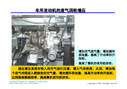
•
废气涡轮增压 将发动机排气引入涡轮机,利
用废气能量推动涡轮机旋转, 由此驱动与涡轮同轴的压气机 气波增压 利用排气压力波使空气受到压缩,以 实现增压。 提高进气压力的方式
•
•
复合增压
School of Mechanical & Automotive Engineering South China University of Technology
2.
难点
1) 2) 3) 4)
School of Mechanical & Automotive Engineering South China University of Technology
第一节 概述
从实际应用的情况来 看,较为常见的是 涡 轮 增压和机械增压, 其 中 涡轮增压占了绝大 部 分 ,而机械增压则在 近 年 来重新得到重视, 发 展 较快。
排气经涡壳引导进 入叶片式喷管,在 流经喷管时降压、 降温,增速膨胀, 将压力能转化成动 能,推动叶轮旋转。 废气沿径向流入涡轮机,沿轴向流出涡轮机。
School of Mechanical & Automotive Engineering South China University of Technology Copyright © 2012. All rights reserved.
1 – 进气道 2 – 工作轮 3 – 扩压器
4 – 出气涡壳
空气沿轴向流入压气机,沿径向流出压气机。 空气经进气管进入压气机叶轮,并在离心力作用下从叶轮中心流向 叶轮周边。从旋转的叶轮获得能量,在扩压器中减速增压。在蜗壳 School of Mechanical & Automotive Engineering S中继续减速增压,完成动能向压力能的转化 outh China University of Technology Copyright © 2012. All rights reserved.
Infineon-AN2011_05_IGBT_Modules_Explanation-AN-v1.1-en

3.10 Dynamic behavior ............................................................................................................................18 3.11 Short circuit ......................................................................................................................................20 3.12 Leakage currents ICES and IGES ........................................................................................................21 3.13 Thermal characteristics ....................................................................................................................21 4 Datasheet parameters Diode ....................................................................................................................22 4.1 4.2 4.3 4.4 Diode forward characteristic ............................................................................................................22 Repetitive peak forward current .......................................................................................................23 I t value ............................................................................................................................................23 Reverse recovery .............................................................................................................................23
管子智能生产线工艺布置设计

Shipbuilding Technology Research管子智能生产线工艺布置设计韦 刚,殷 超,吴思远(招商局重工(江苏)有限公司,江苏海门 226100)摘 要:为了满足多元化船舶产品生产需要,设计一种具有高柔性、高效率的综合管子智能生产线的工艺布置。
它在硬件上符合DN 40~DN 400管径碳钢管加工工艺流程要求,在软件上与公司现有的ERP 系统对接,并自带MES 系统,实现全自动区及半自动区的信息及物流顺畅贯通。
所设计的工艺布置兼顾智能、高效、柔性生产特点,工艺适应范围广,产能可扩展,管子智能生产线规划方案理念及配置先进,符合智能化发展方向。
关键词:DN 40~DN 400管径碳钢管;工艺布置;智能化;ERP 系统中图分类号:U664.82 文献标志码:A DOI :10.14141/j.31-1981.2021.02.020Process Layout Design of Intelligent Pipe Production LineWEI Gang, YIN Chao, WU Siyuan(China Merchants Heavy Industry (Jiangsu) Co., Ltd., Haimen 226100, Jiangsu, China)Abstract: In order to meet the production demand of diverse ship products, a kind of process layout of integrated pipe intelligent production line with high flexibility and efficiency is designed. It meets the processing technology process requirements of DN 40~DN 400 pipe diameter carbon steel pipe in hardware and connects with the company's existing ERP system in software, and has its own MES system to realize the smooth connection of information and logistics in the automatic area and the semi-automatic area. The designed process layout has the characteristics of intelligent, high efficient and flexible production. The process is adaptable to a wide range. The production capacity can be expanded. The idea and configuration of the intelligent production line planning scheme of pipe are advanced, which is in the line with the direction of intelligent development.Key words: carbon steel pipe with diameter of DN 40~DN 400; process layout; intelligent; ERP system基金项目:2020年江苏省工业和信息产业转型升级专项资金项目“智能薄板分段生产线及管子加工中心建设项目”。
氯离子与有机添加剂协同作用对铜箔组织性能的影响

第15卷第2期2024年4月有色金属科学与工程Nonferrous Metals Science and EngineeringVol.15,No.2Apr. 2024氯离子与有机添加剂协同作用对铜箔组织性能的影响孙桢1, 黄剑1, 宋宁1, 樊小伟1, 廖娟1, 王丽娟1,唐云志*1, 谭育慧1, 陆冰沪2, 李大双2(1.江西理工大学材料冶金化学学部,江西 赣州 341000; 2.安徽铜冠铜箔集团股份有限公司,安徽 池州 247100)摘要:随着锂离子电池产业的发展,负极集流体用铜箔正朝着高抗拉强度、高延伸率以及极薄尺寸的趋势发展。
本实验通过探讨镀液中Cl -、SPS 和胶原蛋白添加剂协同作用对铜箔微观形貌及力学性能的影响规律,制备了抗拉强度为502 MPa 、延伸率达5.1%的高性能铜箔。
利用SEM 、TEM 、XRD 、激光共聚焦显微镜表征了铜箔的表面形貌和织构,采用万能试验机、电化学工作站和接触角测试仪评估铜箔的力学强度、电化学性能及表面润湿性。
结果表明,Cl -和SPS 的协同效应有利于铜箔晶粒细化,促使Cu (220)晶面取向增加,提高了铜箔的力学性能。
Cl -、SPS 和胶原蛋白的组合添加协同作用进一步增强了铜箔(220)晶面取向,织构系数Tc 达到 52%,显著提高了铜箔抗拉强度、延伸率和表面润湿性能。
关键词:添加剂;电沉积;晶粒细化;极化作用中图分类号:TG113.2 文献标志码:AEffects of the synergistic interaction of Cl - and organic additives on the organization and properties of copper foilSUN Zhen 1, HUANG Jian 1, SONG Ning 1, FAN Xiaowei 1, LIAO Juan 1, WANG Lijuan 1,TANG Yunzhi *1, TAN Yuhui 1, LU Binghu 2, LI Dashuang 2(1.Faculty of Materials Metallurgy and Chemistry , Jiangxi University of Science and Technology , Ganzhou 341000, Jiangxi , China ;2. Anhui Tongguan Copper Foil Group Co., Ltd., Chizhou 247100, Anhui , China )Abstract: With the development of the lithium-ion battery industry, copper foil for negative current collectors is moving toward higher tensile strength, higher elongation, and extremely thin dimensions. By exploring the synergistic interaction laws of Cl -, SPS, and collagen additives in the plating solution on the microscopic morphology and mechanical properties of copper foil, high-performance copper foils with a tensile strength of 502 MPa and elongation of 5.1% were prepared in this experiment. The surface morphology and texture of the copper foil were characterized by SEM, TEM, XRD and laser confocal microscopy. Its mechanical strength, electrochemical properties, and surface wettability of copper foil were evaluated by the universal testing machine, electrochemical workstation and contact angle tester. The results showed that the synergistic effect of Cl - and SPS favored the grain refinement of copper foil, increased the Cu(220) crystal plane orientation, and improved the mechanical properties of copper foil. The synergistic effect of Cl -, SPS and collagen further improved the copper收稿日期:2023-03-02;修回日期:2023-04-21基金项目:江西省自然科学基金重点基金资助项目(20202ACB202001);江西省重点研发计划项目(20212BBE51018、20224BBE51045);江西省教育厅项目(GJJ210831)通信作者:唐云志(1975— ),博士,教授,主要从事高性能铜箔的制备与表面处理的研究工作。
SIWAREX WT231 weighing终端说明书

Stand-aloneOverviewPlatform and hopper scales / SIWAREX WT231 weighing terminalPlatform and hopper scales / SIWAREX WT231 weighing terminal2/70SIWAREX WT231 weighing terminalThe SIWAREX WT231 is a weighing terminal for industrial use.Siemens standard components are installed in a stainless steelenclosure with numerous connection options. This ensures the tried and tested SIWAREX quality for stand-alone solutions and is alsoideal for hopper scales and platform scales.SIWAREX WT231 offers the following key advantages:•Complete solution – no configuration in SIMATIC required•Fast and easy commissioning due to intuitive operating concept •Stainless steel enclosure permits applications in many diverse environments•Integrated terminals for up to 4 load cells (1 … 4 mV/V)•Flexible connection to different systems through diverse choice of interfaces:-Four digital inputs (24 V DC)-Four digital outputs (24 V DC)-One analog output (0/4 … 20 mA)-RS 485 interface and Modbus RTU•High resolution of load cell signal of up to ± 4 million parts •Comprehensive diagnostics functions•All diagnostic and error messages, as well as all scale parameters,in plain text•Recovery point for simple restoration of all parameters•Automatic calibration is possible without the need for calibration weights•Simulation mode•Three freely programmable limit valuesSIWAREX WT231 is the optimum solution wherever strain gauge sensors, such as load cells, force sensors or torque measuring shafts, are used for measuring tasks. The following are typical SIWAREX WT231 applications:•Non-automatic weighing instruments •Fill-level monitoring of silos and bins •Measuring of crane and cable loads•Load measuring for industrial elevators and rolling mills•Force measuring, hopper scales, platform scales and crane scalesSIWAREX WT231 is a stand-alone weighing terminal based on the tried and tested Siemens SIWAREX WP231 products and theSiemens SIMATIC KTP 400 touch display. Along with a connection board and a wide-range power supply, these components are preinstalled in a compact, stainless steel enclosure.The enclosure can be wall mounted and has 9 cable entries, of which 5 are equipped with cable glands at the factory. A variety of interfaces support the integration into the plant environment.The SIWAREX WT231 is preconfigured with the SIWAREX "Ready-for-use" software. This means that no further commissioning isrequired in SIMATIC.The primary task of SIWAREX WT231 is the measurement and conversion of sensor voltage into a weight value. Up to three interpolation points are used for the weight calculation. The signal can also be digitally filtered if required.Weighing functionsThere are commands available for zeroing and taring. Up to three different tare default values can be activated. The SIWAREX WT231is calibrated at the factory. This means the scale can be automatically adjusted without adjustment weights, and modules can be replaced without the need to readjust the scale.Monitoring and control of the scale signals and statesIn addition to weight determination, the SIWAREX WT231 monitorstwo freely programmable limits (optionally min/max) as well as the empty range. A violation of the limit values is signaled.SIWAREX WT231 operating view "Limit values"SoftwareThe touch panel is preconfigured with the SIWAREX "Ready-for-use"software. This gives the user interface a clear structure and makes it intuitive to operate: English, German, French and Chinese versions are available. The structured menu-based operation facilitates the operation of the scale and supports the user through guided commissioning.A variety of diagnostics options is also offered: Using the trace function, weighing histories can be recorded and exported. A further option also makes it possible to simulate the behavior of the scale.The service tool "SIWATOOL V7", which is included in the optional configuration package, is required for reading out this trace data. In addition, using SIWATOOL a scale backup can be created and reimported whenever required. This means that in the event of a fault,the WT231 can be replaced within seconds, without the need for recalibration.Siemens WT 10 · 2022Stand-aloneWeighing Electronics© Siemens AG 2022Stand-alonePlatform and hopper scales / SIWAREX WT231 weighing terminal2/71Integration in the plant environmentUsing the onboard RS 485 interface and the Modbus RTU protocol,the SIWAREX WT231 can be connected to a wide range of different automation systems or to a PC.Four digital inputs, four digital outputs und one analog output are also available. Direct, straightforward further processing of alarms or status messages is thus made possible.Siemens WT 10 · 2022Weighing ElectronicsStand-alonePlatform and hopper scales / SIWAREX WT231 weighing terminal2/72Siemens WT 10 · 2022Weighing Electronics。
IR2104 + IRF540 MOS电机驱动全桥 学习与实践过程

使用L293或L298等全桥芯片来控制直流电机虽然简便而且成本低廉,但由于它们的内阻较大,在控制大电流的马达时芯片常常过热,导致系统的整体效率较低。
在电动车上,马达控制芯片的内阻过大会导致车子的加速度变小。
本人设想在暑假制作一个大的轮式或者履带式机器人,并且希望它能跑到公交车那么快,于是开始研究如何使用MOS管来控制更大电流的电机。
首先,本人参考了《大功率直流马达的驱动——ABU ROBOCON 2005比赛之动力方案》一文中的电路图(原文地址/article.php?sid=192 )按照这个原理图,我热转印制作了单个全桥的实验电路。
个别的电阻电容值有所变动。
分了三路电源,5V给74HC00,10-20V的给2104,还有10-100V的给马达。
都没做稳压。
这玩意对电源要求比较高。
2104一掉电很容易烧。
日本人的图的逻辑不对,我当年犯二,没注意想就抄了,把门去了就对了.还有,老烧板到最后发现是电源的问题,线性稳压很容易被击穿,要注意防反向电动势!上电并给予有效的持续高电平信号后发现电路不能驱动马达,而2104开始发烫,540没有任何反应。
于是更换2104,但仍出现同样的现象。
通过示波器检测发现,高端MOS没有被驱动,而低端MOS的G 端信号正常,因而桥没有被导通。
更换信号方向,另外半桥仍然出现相同的现象。
本人开始怀疑是BOOTSTRAP电容的问题,于是实验了不同的电容值。
但无论怎么变换,问题仍然没有被解决。
由于手头没有4148,使用了IN5819作为续流二极管,按道理5819只会比4148更好,不应该成为问题的原因。
由于手头2104只有6片,而所有的都上电并且发热过,于是重新购买了一批2104。
在这里感谢周顺同学,那天刚好他毕业考考好,帮我到科技京城买了2104。
更换2104后,电路工作正常。
周顺看了看我原来的2104,恍然大悟:原来的芯片是97年前的旧货。
马达欢快地转了起来。
由于540的内阻要比298小很多,马达的加速度明显提高,变向时电刷更是发出了闪亮的火星。
天然气增压开采工艺技术罗波
天然气增压开采工艺技术罗波发布时间:2021-11-03T01:51:23.834Z 来源:《中国科技人才》2021年第20期作者:罗波[导读] 随着社会的不断发展,人们对环境保护的观念与意识也在不断的提升。
长庆油田分公司第二采气厂陕西榆林 719000摘要:随着社会的不断发展,人们对环境保护的观念与意识也在不断的提升。
而在当前环境形式日益加剧的形势下,天然气的开发也面临着更加艰巨的挑战。
即在天然气后期开采的过程中,增压开采技术的有效应用可以有效的提升天然气的开采质量,使天然气开采活动所面临的困境得到缓解。
本文简要介绍了天然气增压开采工艺技术的概念以及应用现状,在提出行之有效的策略的同时希望能为相关行业提供可参考的建议。
关键词:天然气;增压开采;工艺技术引言随着社会经济的不断发展与进步,世界所需资源的总量也在与日俱增。
天然气作为一种新型能源因其较高的生产效率与较低的环境污染优势被广泛的运用着。
而天然气增压开采技术对于天然气的开采有着十分重要的作用。
不仅能够有效的提升天然气利用效率,同时在开采过程中对于环境的影响也相对较小,因此被广泛的应用到天然气开采过程中。
一、天然气增压开采天然气增压开采通常情况下是指在天然气开发的后期对井部气压进行改造从而通过压强的改变使得外输液态压力不足的状态得到有效缓解的一种工艺方式。
对于我国来说,该方式可以有效的改善我国能源开采和效率优化的问题,使我国绿色无污染能源开发的进程大大加快。
二、天然气增压开采的方法分析由于我国各地地质地域和相关企业的天然气采集要求有所不同,因此天然气增压开采所运用的方法也有所不同,不同的方法之间存在的不同的特征与优势。
而我国主要运用的天然气增压方法主要包括分散式增压、区域性增压、集中性增压以及集气增压几种。
1.单井增压单井增压具有强度可控、适用情况多的特点。
这也就使得这种方式能够不用受到气田开采比例问题的影响。
但是单井增压的不足在于其产量有限,如果工作量较大的话就需要设置较多个增压井点,这样一来工作量会增加很多,而且后期的维护与运营成本也会增加。
- 1、下载文档前请自行甄别文档内容的完整性,平台不提供额外的编辑、内容补充、找答案等附加服务。
- 2、"仅部分预览"的文档,不可在线预览部分如存在完整性等问题,可反馈申请退款(可完整预览的文档不适用该条件!)。
- 3、如文档侵犯您的权益,请联系客服反馈,我们会尽快为您处理(人工客服工作时间:9:00-18:30)。
8 7 6 5 4 3 2 1 0
Viscosity (Pas)
10 10 10 10 10 10 10 10
3890.5γ
-1 -1.1
288403.2γ 2454.7γ 467.7γ
-6
-0.84 -0.95
45185.6γ 1659.6γ
10
-5
-1 -2
Aluminium melt Graphite tube
Piston Process
Graphite crucible
Die Casting
Lowcost
Good control flexibility
Suitable for a variety of alloy
17
1
4
2
5
3
6
Rheo-casting slug
SSM provides a new way for low-cost and high quality products.
SSM has inherently better durability than cast product and has lower costs than MFS. Rheo-castings can get the similar mechanical properties as thixocastings. But the cost is much lower .
2
3
Horizontal Section
319S aluminum alloy Al-6%Si-3%Cu-0.3%Mg modified by Sr
Vertical section
4
100
90 80
Fraction liquid (%)
70
60 50
40 30
A356 A357 2014 6082 7075 7010
Liquid Fraction:about 50%
8
Compressor wheel Tooling Real-time controlled Buhler die casting machine
Tooling is made up of 14 petals that fit into a carrier ring
25
MIM process
Microstructure
Homogeneous microstructure. Fine grains. Casting defects free
Mechanical properties
Alloy Cast In713c Rupture Rm(MPa) 850 Yield Rp0.2(MPa) 740 Elongation(%) 8
10
Semisolid metal flow behavior:(non-Newtonian)
When the shear rate is high, the solidifying dendrites are broken and the fluidity is increasing (the viscosity is decreasing).
Sintered MIM713c
HIPped MIM713c
1082
1375
916
959
12
25
26
GRINM leads developing MIM turbine wheels together with the University of Science and Technology Beijing, Beijing Institute for Materials and WeiFu Technologies Ltd. Key know-hows on die design, injection, vacuum sintering and HIP etc have been gained. Turbine wheels with density more than 99.5% have been achieved.
1
Introduction to the compressor wheel Material selection for the SSM process Thixo-casing process
2
3
34 5 6
Rheo-casting process Concluding Remarks Future works
10 8 6 4 2 0
Casting 354.0
Casting C355
SSM Thixo-casting 319s
Forging 2618
15
Elongation (%)
319s SSM compressor wheel
Casting compressor wheel
The fatigue life of compressor wheels provided by different methods
18
Filling ability
Microstructure
(a)
Silicon Particles
Rheo-casting
a
Thixo-casting
(c)
19
20
SSM has been successfully applied to manufacture very complex geometry turbocharger compressor wheels and now in production.
was improved on the basis of Power Law model.
Power Law Cut-off model
a 0 K if
n
0
a 0 K 0 if
n
0
Viscosity decreasing phenomenon in filling process
Turbine wheels manufactured by Metal Injection Moulding (MIM)
A turbine wheel works under the conditions of high temperature, corrosive environment, cyclic speed and resonance frequency of blade
Compressor wheel
Biscuit
Overflow and vent
Runner
9
Front view
Left view
Filling direction of the semi-solid slurry
Material tracing video(Simulation) The red part of the slug will fill into the compressor wheel cavity.
Tensile properties (Holset Spec) of casting vs forging vs SSM materials
160
Density corrected stress (MPa / g/mm )
3
140 120 100 80 60 40 20 0
UTS YS Elongation
21
Cost
MFS
Thixocasting
SSM
201 alloy
Ideal
Cast
SSM
Rhrocasting
Durability
22
Report in 2015
Turbine wheels manufactured by Metal Injection Moulding (MIM)
23
Future works to be reported in 2015
319s DSC test Heating Cooling
7075
A357
7010
Rheoprocessing, Thixomolding
Thixoforming
A356 2014
20 10
0 450 500 550 600 650 6082
Thixoforging
700பைடு நூலகம்
Temperature (° C)
-1.25 -1.38
-2
10
10
-4
10
-3
10
10
-1
10
0
10
1
10
2
10
3
10
4
Shear rate (1/s)
11
Nowadays, viscosity modelling for semi-solid alloy slurry usually use the Power Law model, the Carreau model, the Cross model and the Bingham Model etc. In our work,we use the Power Law Cut-Off model (PLCO)which
12
Simulation results
13
Partial filling experiment
Casting C355, 354.0
Thixo-casting 319s
MFS 2618
3D X-ray CT test of the Thixo-casting compressor wheel
14
The working performance of Thixo-casting and traditional casting compressor wheel
