ams1070m电流计使用说明书
AMS1000 说明书

AMS1000 说明书气体质量流量计⚫集成质量流量与温度测量⚫重复性好⚫支持多种气体测量⚫标准Modbus-RTU通信⚫2个NPN集电极开路输出(用于上下限报警)⚫1~5V线性电压输出或4~20mA线性电流输出⚫LCD屏显示⚫9~24V DC电源供电应用范围AMS1000适用于空气、氮气、氩气、二氧化碳、氦气、氧气等干燥洁净无腐蚀性气体(易燃易爆炸气体除外)的质量流量监测。
已被广泛应用于高校科研、消防、环境监测、烟草、智慧农业、食品、医药等行业。
图1. AMS1000产品简述AMS1000是一款热式质量流量传感器,通过测量电阻变化计算被测量气体的质量流量。
传感器采用自主研发的MEMS质量流量芯片,具有直观、精准、稳定、耐高低温、线性好、响应时间短等特点。
出厂前对AMS1000的量程、精度、重复性、响应时间等均进行了严格的校准。
1.外观结构及接口定义1.1 外观结构图2展示的是AMS1000的外观结构及工作界面,包含了传感器风道和工作界面等。
工作界面包括LCD显示屏和操作按键,LCD显示的内容有流量计Modbus通信地址、气体温度、累积流量及瞬时流量。
按键包括向上、向下、DISP和MODE四个按键。
传感器风道在工作界面下方,包括进气口和出气口,且传感器上标明了气流的方向。
图2. AMS1000结构示意图1.2 设备DB9公头DB9公头的针脚定义,如图3和表1所示。
图3.DB9公头针脚示意图表1.DB9公头针脚定义针脚定义1 外部输出12 模拟输出3 RS485B4 RS485A5 电源线6 GND7 GND8 GND9 外部输出2 1.3 AMS1000引出线(DB9母头)若购买AMS1000引出线,引出线与针脚关系如图4所示。
图4.DB9引出线与针脚关系图2.AMS1000技术指标及机械参数表2. AMS1000技术指标及机械参数参数描述型号AMS1000H00 AMS1000H01 AMS1000H02 AMS1000A00 AMS1000A01 AMS1000A02 量程0~200L/min 0~20L/min 0~2L/min 0~200L/min 0~20L/min 0~2L/min精度±4%RD(2≤x≤50L/min)±2%RD(50<x≤200L/min)±4%RD(0.2≤x≤5L/min)±2%RD(5<x≤20L/min)±4%RD(0.02≤x≤0.5L/min)±2%RD(0.5<x≤2L/min)±4%RD(2≤x≤50L/min)±2%RD(50<x≤200L/min)±4%RD(0.2≤x≤5L/min)±2%RD(5<x≤20L/min)±4%RD(0.02≤x≤0.5L/min)±2%RD(0.5<x≤2L/min)产品重量565g 330g 565g 330g输出方式RS485、NPN集电极开路输出、1~5V线性电压输出RS485、NPN集电极开路输出、4~20mA线性电流输出重复性±1%F.S.响应时间50ms供电方式外部电源9~24V DC显示方式LCD显示屏显示单位累计流量:L(ft3×10-1)瞬时流量:L/min(CFM×10-2)最大工作压力0.8MPa标准校准气体空气(25℃,1个标准大气压)工作温度-10~+60℃引出线DB9母头数据线(非标配)功耗0.85W(典型)外壳材料PC风道材料6061铝合金3.产品主要尺寸图AMS1000H00、AMS1000A00尺寸如下图。
多功能电流计操作流程

多功能电流计操作流程一、介绍多功能电流计是一种用于测量电流的仪器,具有多个功能和应用。
本文将介绍多功能电流计的操作流程,帮助读者正确、高效地使用此仪器。
二、准备工作1. 确认电流计的型号和规格,了解其使用方法和特点。
2. 检查电流计的外观是否完好,无损伤。
必要时进行清洁。
3. 准备所需的电源和连接线,确保电源正常工作。
三、连接电源1. 将电源线插入电流计的电源插座。
2. 将电源线的另一端插入适配器或电源插座,确保连接牢固。
3. 打开电源开关,确认电流计已经成功通电。
四、连接被测电路1. 停止被测电路的工作状态,确保安全。
2. 将电流计的测量端口分别与被测电路的正负极相连。
3. 注意连接的稳固性,确保信号传输的可靠性。
五、选择测量模式1. 根据被测电路的特点和需求,选择合适的测量模式。
多功能电流计通常提供直流、交流和其他特殊模式的选择。
2. 在电流计上找到相应的模式设置按钮或旋钮,按照说明调整到所需的模式。
六、校准电流计1. 进入校准模式,按照电流计的说明书进行校准操作。
2. 按照校准操作指引,根据被测电路的参考电流值进行校准,确保电流计的准确度。
七、进行测量1. 打开被测电路,使其正常工作。
2. 观察电流计的读数,记录下测量结果。
3. 如有需要,可以连续测量多次,取平均值以提高准确性。
4. 注意观察电流计的量程范围,确保读数在可承受范围内。
八、数据处理与记录1. 将测量结果记录下来,包括时间、测量值、测量模式等相关信息。
2. 如需进一步处理数据,可使用电脑或其他设备进行分析、生成图表等操作。
九、结束测量1. 关闭被测电路,断开电流计与电路的连接。
2. 关闭电流计的电源开关,断开电源线连接。
3. 清理和整理电流计及相关设备,确保其安全、干净。
总结:本文介绍了多功能电流计的操作流程,包括准备工作、连接电源和被测电路、选择测量模式、校准电流计、进行测量、数据处理与记录以及结束测量等步骤。
通过正确操作,能够准确测量电流并记录测量结果,提高工作效率和准确性。
Omega 流量监测仪产品文档说明书
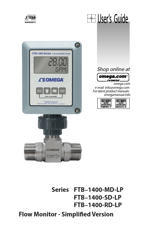
e-mail:**************For latest product manuals:Shop online atSeries FTB–1400-MD-LP FTB–1400-SD-LP FTB–1400-RD-LPFlow Monitor - Simplified VersionServicing North America:Servicing Europe:U.S.A.:Omega Engineering, Inc., One Omega Drive, P.O. Box 4047ISO 9001 Certified Stamford, CT 06907-0047Toll-Free: 1-800-826-6342Tel: (203) 359-1660FAX: (203) 359-7700e-mail:**************Canada:976 BergarLaval (Quebec), Canada H7L 5A1Toll-Free: 1-800-826-6342TEL: (514) 856-6928FAX: (514) 856-6886e-mail:*************For immediate technical or application assistance:U.S.A. and Canada:Sales Service: 1-800-826-6342/1-800-TC-OMEGA ®Customer Service: 1-800-622-2378/1-800-622-BEST ®Engineering Service: 1-800-872-9436/1-800-USA-WHEN ®Mexico:En Español: 001 (203) 359-7803FAX: (001) 203-359-7807**************.mxe-mail:*****************Benelux:Managed by the United Kingdom Office Toll-Free: 0800 099 3344TEL: +31 20 347 21 21FAX: +31 20 643 46 43e-mail:**************Czech Republic:Frystatska 184733 01 Karviná, Czech RepublicToll-Free: 0800-1-66342TEL: +420-59-6311899FAX: +420-59-6311114e-mail:*****************France:Managed by the United Kingdom OfficeToll-Free: 0800 466 342TEL: +33 (0) 161 37 29 00FAX: +33 (0) 130 57 54 27e-mail:**************Germany/Austria:Daimlerstrasse 26D-75392 Deckenpfronn, GermanyToll-Free************TEL: +49 (0) 7059 9398-0FAX: +49 (0) 7056 9398-29e-mail:*************United Kingdom:OMEGA Engineering Ltd.ISO 9001 Certified One Omega Drive, River Bend Technology Centre, NorthbankIrlam, Manchester M44 5BD EnglandToll-Free: 0800-488-488TEL: +44 (0)161 777-6611FAX: +44 (0)161 777-6622e-mail:**************.uk OMEGAnet ® Online Service Internet e-mail **************It is the policy of OMEGA Engineering, Inc. to comply with all worldwide safety and EMC/EMI regulations that apply. OMEGA is constantly pursuing certification of its products to the European New Approach Directives. OMEGA will add the CE mark to every appropriate device upon certification.The information contained in this document is believed to be correct, but OMEGA accepts no liability for any errors it contains, and reserves the right to alter specifications without notice.WARNING: These products are not designed for use in, and should not be used for, human applications.CONTENTSINTRODUCTION . . . . . . . . . . . . . . . . . . . . . . . . . . . . . . . . . . . . . . . . . . . . . . . . . . . . . . . . . . .4 SPECIFICATIONS . . . . . . . . . . . . . . . . . . . . . . . . . . . . . . . . . . . . . . . . . . . . . . . . . . . . . . . . . .6 OPERATING THE MONITOR . . . . . . . . . . . . . . . . . . . . . . . . . . . . . . . . . . . . . . . . . . . . . . . .7 BASIC PROGRAMMING MODE . . . . . . . . . . . . . . . . . . . . . . . . . . . . . . . . . . . . . . . . .7 PROGRAMMING . . . . . . . . . . . . . . . . . . . . . . . . . . . . . . . . . . . . . . . . . . . . . . . . . . . . . . .7 FTB–1400 Simplified 4-20 mA Programming . . . . . . . . . . . . . . . . . . . . . . . . .10 ADDITIONAL INPUT OPTIONS . . . . . . . . . . . . . . . . . . . . . . . . . . . . . . . . . . . . . . . . . . .12 TROUBLESHOOTING GUIDE . . . . . . . . . . . . . . . . . . . . . . . . . . . . . . . . . . . . . . . . . . . . .17 DEFAULT K-FACTOR VALUES . . . . . . . . . . . . . . . . . . . . . . . . . . . . . . . . . . . . . . . . . . . . .17 PART NUMBERING . . . . . . . . . . . . . . . . . . . . . . . . . . . . . . . . . . . . . . . . . . . . . . . . . . . . . .18 REPLACEMENT PARTS . . . . . . . . . . . . . . . . . . . . . . . . . . . . . . . . . . . . . . . . . . . . . . . . . . .183INTRODUCTIONThe FTB–1400 Flow Monitor is a state-of-the-art, digital signal processing flow monitor, designed to provide the user with exceptional flexibility at a very affordable price . Though designed for use with Omega FTB–1400 flow meters, this display can be used with almost any flow meter producing a low amplitude AC output or contact closure signal(s) .This flow monitor is capable of accepting a low-level frequency input for calculating flow rate and total . These calculations can then be displayed in the desired units of measurement . All FTB–1400 flow monitors come pre-calibrated, from the factory, if ordered with an Omega FTB–1400 Flow Meter . If required, however, it can easily be re-configured in the field . The monitor’s large 8 digit by .75" numeric liquid crystal display makes extend-ed range viewing practical . The second 8 digit by .38" alphanumeric display provides for selectable units viewing in run mode and prompts for vari-ables in program mode . Finally, the user can choose between displaying rate, total, or alternating between both rate and total .Figure 1: Flow Monitor Face4FEATURES• Displays Rate and/or Total• Large 0 .75 Inch, 8 Digit Display for Easy Viewing• Simple, Front Panel Programming• Various Mounting Styles Available• NEMA 4X Suitable for Outdoor Mounting• Intrinsically Safe• Microprocessor Based, Low Power Components• 4-20 mA Loop Powered• Automatic Decimal Point Locating• Lead Zero Blinking• Surface Mount Technology Use Throughout5SPECIFICATIONSPower Supply:4-20 mA loop powerPower Consumption:25 mA (maximum)Alphanumeric Rate and Total Display:8 digit, .75" high numeric display8 character, .38" high alphanumeric displayFixed or toggle modes of operation for flow rate and totalizer display Pulsed Output Signal:Outputs one pulse for each increment of the least significanttotalizer digitMax . Voltage: 30 VdcPulse Type: Opto-Isolated open collector transistorPulseWidthONState:***************************** Magnetic Pick-up Inputs:Frequency Range: 0 to 3500 HzTrigger Sensitivity: 30 mV p-pOver Voltage Protected: ±30 VDCFrequency Measurement Accuracy: ±0 .1%Temperature Drift: 50 ppm / ºC (max)Transient Overvoltages: Category 3, in accordance with IEC664 Pollution Degree: 2, in accordance with IEC664Mounting Classification:Meter Mount: NEMA 4X EnclosureRemote Mount: NEMA 4X EnclosureSwivel Mount: NEMA 4X EnclosureEnvironmental:Operating Temperature: -22 ºF to +158 ºF (-30 ºC to +70 ºC)Humidity: 0-90% Non-condensingUnits of Measure:Gallons, Oil Barrels, Liters, Cubic Meters, MGal, Cubic FT, MCF, MMCF Megltrs, Acre FT, Liq . Barrels, LBS, KGSTime Intervals: Day, Hour, Minute, Second6OPERATING THE MONITORThe monitor has two modes of operation referred to as the RUN mode and the PROGRAM mode . Both the run mode and the program mode display screen enunciators confirming the state of the monitor . A quick glance at the lower left hand corner of the LCD screen will confirm operating status . Normal operation will be in the RUN mode . To access the program mode, press the MENU button until the first programming screen is displayed . After programming the display with the necessary information, a lock out feature can be turned on to prevent unauthorized access or changing the meter’s setup parameters .BASIC PROGRAMMING MODEKeys:MENU – Switch between RUN and PROGRAM modesUP Arrow – Scrolls through programming sub-menus in forwarddirection and increments numeric variablesRIGHT Arrow – Scrolls through programming sub-menus in reverse direction and moves the active digit to the rightENTER – Used to enter sub-menus, save programming informationand in the reset processIf your monitor was ordered with an Omega flow meter, the two compo-nents ship from the factory calibrated as a set . If the monitor is a replace-ment, the turbine’s K-factor has changed, or the monitor is being used with some other pulse generating device, programming will be necessary . PROGRAMMINGEach turbine flow meter is shipped with either a K-factor value or frequency data . If frequency data is provided, the data must be converted to a K-factor before programming . K-factor information, when supplied, can usually be found on the neck of the flow meter or stamped on the body . The K-factor represents the number of pulses per unit of volume . The K-factor will be needed to program the monitor .ENTER PRO GRAM MO DE – Change to program mode by press-ing the MENU button once . The mode indicator will change from RUN to PROGRAM .78ton once . The current meter size number will begin to flash . Using the arrow keys, scroll through the size choices until you find the bore size ofyour meter . Press ENTER once to save the meter size choice .Rate / Total DisplayAndProgrammingKeys Mode IndicatorAndProgramming ChoicesFigure 2: Flow Monitor ControlsENTER THE METER’S K-FACTOR UNIT – Directly after the METER size is selected, the display’s K-factor unit must be chosen . Use the UP arrow key to select your K-factor unit . For meters calibrated in gallons, use PUL/GAL (pulses per gallon); for meters calibrated in cubic meters, use PUL/M3 (pulses per cubic meter), etc . Press ENTER to save the K-factorunit and advance to the next parameter .SELECT THE RATE/TOTAL UNITS OF MEASURE – The monitor allows the choice of five common rate/total units . The monitor shows the rate/ total unit that the display is currently set for . If the current selection is correct, press the ENTER key once to advance to the next parameter . To change to an alternate unit, use the arrow keys to scroll to the desiredrate unit and press ENTER to save the choice .SELECT THE DISPLAY FUNCTION – The monitor can display RATE or TOTAL or alternate between BOTH rate and total . At the DISPLAY prompt, press the ENTER key once . The monitor now shows the display mode currently in effect . If the current selection is correct, press the ENTER key to advance to the next parameter . To change to an alternate display mode, use the ar-row keys to scroll to the desired display mode and press ENTER to save the choice .A TEST function is also available in the Display Function sub-menu . With the test function selected, the display acts like a frequency counter and displays the raw input frequency being supplied to the frequency input terminals . This is very useful when troubleshooting flow problems .9TOTALIZER PULSE OUTPUT – The pulse output parameter can be either enabled or disabled . When enabled this output generates 20 mS duration pulse for every time the least significant digit of the totalizer increments . The amplitude of the pulse is dependent on the voltage level of the supply connected to the pulse output and is limited to a maximum 30 VDC . FTB–1400 SIMPLIFIED 4-20 MA PROGRAMMINGFLOW 4mA SETTING – When the loop powered option is ordered, the flow rate that corresponds to 4mA must be set . Zero is default flow rate for this setting . If the current selection is correct, press the ENTER key once to advance to the next parameter . If adjustment is required, use the RIGHT arrow key to select the position of the number you wish to change . Then use the UP arrow key to increment the number . Once you have completed this step, press the ENTER key to advance to the next parameter .FLOW 20mA SETTING – The flow rate that corresponds to 20mA must be set next . The turbine meter’s maximum flow rate is the default value .If the current selection is correct, press the ENTER key once to advance to the next parameter . If adjustment is required, use the RIGHT arrow key to select the position of the number you wish to change . Then use the UP arrow key to increment the number . Once you have completed this step, press the ENTER key to advance to the next parameter .4-20mA CALIBRATIO N – When ordered with a 4-20mA option, this menu item allows the fine adjustment of the 4-20mA output . The 4mA setting is typically between 35 and 50 . To set the 4mA value, connect an ammeter in series with the loop power supply . At the 4mA OUT prompt, adjust the 4mA value to obtain a 4mA reading on the amme-ter . The UP arrow key increments the value and the RIGHT arrow key decrements the value . When a steady 4mA reading is obtained on the ammeter, press the ENTER key to lock in this value and move to the 20mA adjustment . The 20mA adjustment is performed using the same procedure as the 4mA adjustment .4-20mA TEST – The monitor contains a diagnostic routine that allows the simulation of mA values between 4 and 20 to check output track-ing . At the 4-20TEST prompt the arrow keys change the simulated mA output in increments of 1mA . The ammeter should track the simulated mA output . If a 4-20mA test in not necessary, pressing the ENTER key once will escape the testing at any time .1011Figure 3: Typical Ammeter ConnectionPASSWO RD – Password protection prevents unauthorized users fromchanging programming information . Initially, the password is set to all ze-ros . To change the password, simply enter any 4 digit code using the arrow keys as previously described to enter the password value . Pressing ENTER once will store the password and take you back to the RST PSWD screen .RST PSWD – The reset password screen allows the operator to enter any 4 digit code for the manual reset totals function .RESET TOTAL – To reset the monitor total display, in RUN mode press the MENU and ENTER simultaneously until TOTAL RST starts to flash . The TOTAL RST will stop flashing and the display will return to the RUN mode at the conclusion of the reset procedure .STORE TOTAL – The current total can be manually stored in the monitor’s flash memory . Press and hold the ENTER key for 2 seconds . The display will respond with a flashing TOTALSVD and then return to the RUN mode .AUTOMATIC STORE TOTAL – The monitor is equipped with a store total feature that works automatically, saving the current total to flash memory . The frequency of saves depends on the power supply option chosen .Loop Powered: Once every ten minutes . ADDITIONAL INPUT OPTIONSThe FTB–1400 Flow Monitor is capable of receiving magnetic pick-up input (small signal sine wave) or a contact closure input (pulse) . Since Omega FTB–1400 Flow Meters utilize a magnetic pick-up, the monitor is shipped configured for magnetic pick-up input . To change to a contact closure in-put, remove JP2 from the top two pins and jumper them to the bottom two pins . See Figure 4 .+10 - 30 VDC+1 - 5 VDCFigure 4: Wiring Diagram12Figure 5: Basic Programming Menu13REMOTE DISPLAY14151SWIVEL MOUNTFigure 6: MOUNTING OPTIONSFigure 7: Installation Drawing 16TROUBLESHOOTING GUIDEDEFAULT K-FACTOR VALUES17PART NUMBERINGFTB–1400–X D–LPMounting StyleM -Meter MountR -Remote MountS -Swivel MountREPLACEMENT PARTS18Where Do I Find Everything I Need for Process Measurement and Control?OMEGA…Of Course!Shop online at SMTEMPERATUREThermocouple, RTD & Thermistor Probes, Connectors, Panels & Assemblies Wire: Thermocouple, RTD & Thermistor Calibrators & Ice Point ReferencesRecorders, Controllers & Process Monitors Infrared PyrometersPRESSURE, STRAIN AND FORCETransducers & Strain Gages Load Cells & Pressure Gages Displacement Transducers Instrumentation & AccessoriesFLOW/LEVELRotameters, Gas Mass Flowmeters & Flow Computers Air Velocity IndicatorsTurbine/Paddlewheel Systems Totalizers & Batch ControllerspH/CONDUCTIVITYpH Electrodes, Testers & Accessories Benchtop/Laboratory MetersControllers, Calibrators, Simulators & Pumps Industrial pH & Conductivity EquipmentDATA ACQUISITIONData Acquisition & Engineering Software Communications-Based Acquisition Systems Plug-in Cards for Apple, IBM & Compatibles Datalogging System sRecorders, Printers & PlottersHEATERSHeating CableCartridge & Strip Heaters Immersion & Band Heaters Flexible Heaters Laboratory HeatersENVIRONMENTALMONITORING AND CONTROLMetering & Control Instrumentation Refractometers Pumps & TubingAir, Soil & Water MonitorsIndustrial Water & Wastewater TreatmentpH, Conductivity & Dissolved Oxygen InstrumentsM-5299/0613☑☑☑☑☑☑☑☑☑☑☑☑☑☑☑☑☑☑☑☑☑☑☑☑☑☑☑☑☑☑☑☑☑。
水流计使用方法说明书
水流计使用方法说明书使用方法说明书一、产品说明本说明书主要介绍水流计的使用方法。
水流计是一种用来检测流体流量的仪器,适用于各种液体和气体的流量测量。
本水流计采用先进的技术和高精度传感器,能够准确、稳定地测量流体的流量。
二、使用前准备1.确认产品完整:在开始使用前,检查水流计是否完好无损,并确保配件齐全。
2.仔细阅读说明书:请认真阅读本使用方法说明书,了解产品的结构、性能和使用要求。
3.检查流体参数:在使用水流计时,需要了解被测流体的温度、压力和介质等参数,确保测量的准确性和安全性。
三、使用步骤以下是水流计的使用步骤:步骤一:安装与接线1.选择合适的安装位置:根据实际需要,选择合适的安装位置并固定水流计。
2.连接电源:将水流计的电源接线与电源线连接,确保电源供应稳定。
3.接线:将水流计的信号接线与检测设备接线端口连接,确保信号传输畅通。
步骤二:参数设置1.打开电源:接通电源并确认电源指示灯亮起。
2.进入设置界面:根据产品说明书,进入相应的设置界面。
3.设置参数:根据被测流体的实际参数,按照说明书中的指导进行参数的设置。
步骤三:校准1.开始校准:在校准前,请确保水流计已经预热并稳定工作。
2.按照校准操作说明:根据产品说明书中的校准操作说明,按照要求进行校准。
3.保存校准数据:根据说明书中的指引,将校准数据保存在水流计中。
步骤四:开始测量1.打开水流计:根据产品说明书中的指引,打开水流计并等待其初始化完成。
2.选择测量模式:根据需要选择合适的测量模式,并调整相应参数。
3.开始测量:按下开始按钮,水流计将开始测量流体的流量。
4.记录数据:在测量过程中,可以查看实时数据,并记录需要的数据。
步骤五:维护与保养1.定期清洁:根据产品说明书,定期清洁水流计,确保其正常工作。
2.保护仪器:使用水流计时,请避免剧烈震动和碰撞,保护仪器免受外界损伤。
3.定期维护:按照产品说明书中的要求,定期对水流计进行维护和保养。
四、注意事项1.安全使用:使用水流计时,请遵守相关安全操作规程,确保人员和设备的安全。
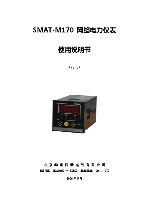
SMAT-M170说明书
SMAT-M170 网络电力仪表使用说明书(V2.0)北京华东西瑞电气有限公司BEIJING HUADONG — XIRUI ELECTRIC CO. , LTD2006年5月一、产品简介◆单相电流测量、开关量输入、实时显示、参数设定、网络通讯于一体;◆先进的交流采样软件和精密可靠的硬件电路相结合,所有仪表均可分散就地安装或集中组屏安装;◆完全取代模拟式电表、变送器;既可单独作为盘装电表使用,也可作为电力监控系统的前端采集装置;◆标准的外观设计,可与多种标准常规指针仪表互换,单行LED显示,允许在高光照环境中读表;◆强大的网络通讯功能,可与RTU、PLC及多种工控软件实现网络通讯,构成分布式综合电力监控系统;◆外型尺寸:48×48×91mm;◆固定方法及开孔尺寸:采用盘装仪表固定方式,开孔尺寸为46×46 mm,由一个套框支架固定;◆包装说明:主机1台,固定套架1套,产品合格证1张。
【应用领域】●电力自动化监测系统●智能型开关柜、配电盘●工业动力监视、管理●分布式综合电量采集系统●邮电、铁路负荷监测●电量参数就地显示、变送二、SMA T-M170功能◆测量内容:单相电流;测量精度为0.5%;◆2路开关量光隔输入,为有源接点;◆标准RS485通讯接口;MODBUS通讯协议;◆各种参数均可通过前面板设定(密码保护)或软件设定;◆电源电压:AC175~265V或AC/DC85~265V(订货时须注明);◆工作温度:环境温度:-20℃~+55℃,存储温度:-40℃~+70℃。
三、产品特点◆强大的网络通讯功能标准RS485通讯接口及标准MODBUS通讯协议,通讯地址(1-255)和波特率(19.2L、9600bps)均可设定;所有信号测量数据及仪表参数均可经由RS485串行口读出;通讯距离最长可达1200米,一条双绞线最多可连接128台SMAT-M系列仪表。
◆显示操作简便SMAT-M170网络电力仪表采用LED数码显示,通过按键可进行各种仪表参数设置,所有设定存放在仪表内部的非易失性存贮器中,掉电不丢失,所有设定均有密码保护。
AMS-1070M电流计使用说明书
目录安全使用注意事项 (2)1、概要 (3)2、特征 (3)3、装置规格 (3)4、外观图、各部分名称 (4)5、操作方法 (5)6、注意事项 (7)7、维护保养 (7)为了确保您的安全,请在使用该装置前仔细阅读注意事项。
注意事项:1)开封前请先确认外包装有无损伤。
2)确认包装上注明的物品是否齐全。
(如有遗失、损伤,请与销售商联络。
)3)请仔细阅读本说明书后,按要求正确连接装置、线缆等。
4)装置的使用场所要求不可有强电磁波及震动。
5)请使用规格为额定(单相AC100VAC120V 50/60Hz)的电源,此规格以外不~可使用。
6)请不要在容易接触到水或油的场所使用。
7)装置的使用请不要超出其本身的使用范围以外。
8)装置内含有精密的电子部件,请不要拆卸、改造。
9)搬运中请注意不要滑落、撞击等。
10)请不要揭下注意、警告标贴及铭板。
11)为确保测定的精确度,请一年实施一次定期点检12)装置报废处理时,请作为工业废弃物处理。
因未遵守以上注意事项而造成的装置故障及错误使用所引发的问题,我公司概不负责。
1)本体AMS-1070M ……………………………… 1台2)笔式探头……………………………… 2根3)AC插头(AC100V用)……………………………… 1个4)装卡片……………………………… 1个5)使用说明书……………………………… 1本1、概要本装置是数字式电阻焊接测定装置(微欧计)。
可对多点电阻焊机的次级线缆、启动线缆等因劣化引起的直流电阻值的增加情况进行测定。
另外,对提早发现焊机因螺丝松动、拧紧度不够等引起的接触面氧化等异常现象很有帮助。
测定方法采用了“四端子法”,可以忽略测定端子与被测定物之间的接触电阻。
并且,为了实现对微小电阻的高精度测定,装置内部采用了2.5A的高精度低电流回路、微小电压增幅回路、共通电压回路等手段。
采用读取方便的LED数字显示。
2、特征2-1、良否判定存储功能可存储10组上限电阻值。
阿基斯莫电子产品介绍说明书

4-1462039-2Axicom IM, Signal Relays, 250VAC Contact Voltage Rating, 220VDC Contact Voltage Rating, 100mW Signal Relay Coil Power Rating (DC)Relays, Contactors & Switches > Relays >Signal RelaysInsertion Loss (HF Parameter):-.03dB @ 100MHz, -.33dB @ 900MHzIsolation (HF Parameter):-18.8dB @ 900MHz, -37dB @ 100MHzSignal Relay Coil Power Rating (DC):100 mWContact Voltage Rating:220 VDCFeaturesProduct Type Features Relay Type IM Relay Product TypeRelayElectrical Characteristics Coil Power Rating Class 50 – 300 mW Actuating SystemDC Insulation Initial Dielectric Between Open Contacts 1000 Vrms Contact Limiting Short-Time Current2 A Insulation Initial Dielectric Between Contacts and Coil 1800 Vrms Insulation Initial Dielectric Between Coil/Contact Class 1500 V – 2500 VAVoltage Standing Wave Ration (HF Parameter) 1.06 @ 100MHz, 1.49 @ 900Mhz Insulation Initial Dielectric Between Adjacent Contacts 1800 Vrms Insulation Initial Resistance 1000000 MΩContact Limiting Making Current 2 A Coil Resistance90 ΩContact Limiting Continuous Current 2 A 4-1462039-2 ACTIVEAxicom TE Internal #:4-1462039-2Axicom IM, Signal Relays, 250VAC Contact Voltage Rating, 220VDC Contact Voltage Rating, 100mW Signal Relay Coil Power Rating (DC)View on >Axicom IM|Coil Type BistableContact Limiting Breaking Current 2 AContact Switching Load (Min).1mA @ .0001VContact Voltage Rating220 VDCSignal Relay Coil Power Rating (DC)100 mWSignal Relay Coil Voltage Rating 3 VDCSignal Relay Contact Switching Voltage (Max)220 VDCSignal Relay Coil Magnetic System Bistable, 1 CoilSignal CharacteristicsIsolation (HF Parameter)-18.8dB @ 900MHz, -37dB @ 100MHz Insertion Loss (HF Parameter)-.03dB @ 100MHz, -.33dB @ 900MHz Body FeaturesInsulation Special Features2500V Initial Surge Withstand Voltagebetween Contacts & CoilWeight.75 g[.026 oz]Contact FeaturesContact Plating Material GoldContact Current Class0 – 2 AContact Special Features Bifurcated/Twin ContactsSignal Relay Terminal Type PCB-SMTSignal Relay Contact Current Rating 2 ASignal Relay Contact Arrangement 2 Form C (2 CO)Contact Material PdRu+AuContact Number of Poles2Termination FeaturesTermination Type Surface MountMechanical AttachmentSignal Relay Mounting Type Printed Circuit BoardDimensionsWidth Class (Mechanical)0 – 6 mmWidth 6 mm[.236 in]Height 5.65 mm[.222 in]Length Class (Mechanical)0 – 10 mmLength10 mm[.393 in]Height Class (Mechanical)0 – 6 mmDimensions (L x W x H) (Approximate)10 x 6 x 5.65 mm[.393 x .236 x .222 in] Usage ConditionsEnvironmental Ambient Temperature (Max)85 °C[185 °F]Environmental Ambient Temperature Class70 – 85°CEnvironmental Category of Protection RTVOperating Temperature Range-40 – 85 °C, -40 – 85 °COperation/ApplicationPerformance Type High DielectricPackaging FeaturesPackaging Method ReelOtherAdditional Features Gull WingProduct ComplianceFor compliance documentation, visit the product page on >EU RoHS Directive 2011/65/EU CompliantEU ELV Directive 2000/53/EC CompliantChina RoHS 2 Directive MIIT Order No 32, 2016No Restricted Materials Above ThresholdEU REACH Regulation (EC) No. 1907/2006Current ECHA Candidate List: JUN 2020(209)Candidate List Declared Against: JUL 2019(201)Does not contain REACH SVHCHalogen Content Low Bromine/Chlorine - Br and Cl < 900ppm per homogenous material. Also BFR/CFR/PVC FreeSolder Process Capability Reflow solder capable to 260°CProduct Compliance DisclaimerThis information is provided based on reasonable inquiry of our suppliers and represents our current actual knowledgebased on the information they provided. This information is subject to change. The part numbers that TE has identified asEU RoHS compliant have a maximum concentration of 0.1% by weight in homogenous materials for lead, hexavalentchromium, mercury, PBB, PBDE, DBP, BBP, DEHP, DIBP, and 0.01% for cadmium, or qualify for an exemption to theselimits as defined in the Annexes of Directive 2011/65/EU (RoHS2). Finished electrical and electronic equipment productswill be CE marked as required by Directive 2011/65/EU. Components may not be CE marked. Additionally, the partnumbers that TE has identified as EU ELV compliant have a maximum concentration of 0.1% by weight in homogenous materials for lead, hexavalent chromium, and mercury, and 0.01% for cadmium, or qualify for an exemption to these limits as defined in the Annexes of Directive 2000/53/EC (ELV). Regarding the REACH Regulation, the information TE provides on SVHC in articles for this part number is based on the latest European Chemicals Agency (ECHA) ‘Guidance on requirements for substances in articles’ posted at this URL: https://echa.europa.eu/guidance-documents/guidance-on-reachTE Model / Part #YDTS20Z15-19SAV001RECP ASSYTE Model / Part #1-825433-1MOD 2 PINHDR 1X11P.TE Model / Part #160088-1RING TONGUE 20-16 AWG 0.198 X .700 BRTE Model / Part #1-1415537-7RTD1L005TE Model / Part #1586963-104P UMNL PIN HDR ASSY, GWTE Model / Part #10213286-00DIGITAL THERMOPILE SENSORTE Model / Part #1-1546927-212P .325 TRI-BARRIER W/COVERTE Model / Part #1-1415017-1SR6C4012 - V23050-A1012-A551Signal Relays(122)RJ45 Connectors(2) TE Model / Part #6-1462039-8IM41DGR=IM RELAY 100 MW 3 V BisTE Model / Part #CAT-AX41-IM11B IM STANDARD (2 FORM C, 2CO CONTACTS)Compatible PartsAlso in the Series Axicom IMCustomers Also BoughtTE Model / Part #YDTS20Z25-35PNV001RECP ASSYTE Model / Part #YDTS20Z21-35PNV001RECP ASSYDocumentsProduct DrawingsIM41CGR=IM-RELAY 100MW 3V BISEnglishIM41CGR=IM-RELAY 100MW 3V BISEnglishDatasheets & Catalog PagesAxicom Signal and High Frequency Relays (RF Switches) APPLICATION NOTE #2EnglishIM Relay DatasheetEnglishIndustrial Relays Quick Reference GuideEnglishProduct SpecificationsDefinitions RelaysEnglish。
操作指南电流计使用方法说明书
操作指南电流计使用方法说明书一、引言电流计是一种广泛应用于电子工程领域的测试仪器,用于测量电路中的电流强度。
本操作指南将详细介绍电流计的使用方法,旨在帮助用户正确、高效地操作电流计。
二、电流计的基本构造电流计由外壳、显示屏、操作按钮、电池盒等部分组成。
外壳采用耐压材料制成,显示屏采用高分辨率技术,操作按钮设计合理,易于操作,电池盒为电源提供持久的供电。
三、操作步骤1. 准备在操作电流计之前,确保已安装好电池,并确认电流计处于关闭状态。
握住电流计的手柄,让探测头对准待测电路。
2. 打开电流计按下电流计上的电源按钮,显示屏将亮起并显示基本信息,进入待测状态。
3. 设置测量范围根据待测电路的预估电流大小,选择适当的测量范围。
电流计一般提供多个档位供选择,通过按钮进行档位切换。
4. 连接电流计将电流计的探测头与待测电路连接,确保连接牢固。
注意接线的正确性,避免连接错误引起测量结果的误差。
5. 进行测量根据实际需求,选择直流或交流测量模式。
在显示屏上可以清晰地看到经过滤波处理后的电流数值。
6. 结束测量在完成测量后,按下电源按钮将电流计关闭。
四、注意事项1. 使用电流计时,避免在潮湿的环境中操作,以免影响仪器的正常工作。
2. 当电流计长时间不使用时,应将电池取出,以免电池漏液损坏电流计。
3. 尽量避免激烈震动和摔落,保护好电流计的外壳和显示屏。
五、故障排除1. 如果电流计出现显示异常或无法启动的情况,请先检查电池是否安装正确或是否电量低下。
2. 如果测量结果与预期差距较大,可先确认接线是否正确,并检查测量范围是否选择合适。
六、总结本操作指南详细介绍了电流计的使用方法,包括准备、打开电流计、设置测量范围、连接电流计、进行测量、结束测量等步骤。
同时,还提供了注意事项和故障排除的指导。
希望本说明书能够帮助用户正确操作电流计,并获得准确的测量结果。
以上就是电流计使用方法的操作指南,祝您顺利使用电流计并取得满意的测量效果。
电流测试仪的使用方法
电流测试仪的使用方法电流测试仪是一种电力仪器,用于测量电路中的电流。
它通常由一个显示屏、一个电流夹头和一些控制按钮组成。
使用电流测试仪的前提是确保用户具备一定的电路基础知识,并且了解相关的安全操作规程。
首先,在使用电流测试仪之前,用户需要确保电源已经关闭,并且电路中没有任何电流流动。
这主要是为了用户的安全考虑。
在进行任何测试之前,应该检查电流测试仪的外观是否完好,电池是否有足够的电量,并且测量范围与实际测试的电流数值相匹配。
接下来,用户需要将电流测试仪的电源开关打开,然后将测试引线连接到电流测试仪上的电流夹头上。
测试引线有红色和黑色两个插头,需要根据实际情况选择插入到电流夹头的相应位置。
红色插头通常用于连接正极,而黑色插头用于连接负极。
然后,用户需要打开待测电路的电源,并将电流夹头固定在电路中的待测元件上。
电流夹头通常具有一个可以打开和关闭的松紧开关,用户应该确保夹头紧固到位,并确保它与待测元件完全接触,以确保准确测量电流值。
在连接好电流测试仪之后,用户可以通过观察仪器上的显示屏来读取电流数值。
通常,显示屏上会显示电流的数值以及单位。
用户应该确保读数不超过电流测试仪的额定测量范围,以免对仪器造成损坏。
除了测量直流电流之外,电流测试仪还可以用于测量交流电流。
在测量交流电流时,用户应该确保电流测试仪的测量范围选择正确,以便准确读取交流电流的数值。
此外,用户还可以根据测量需要选择不同的测量模式,比如平均值模式、峰值模式或者有效值模式。
在使用电流测试仪期间,用户还应该注意以下几点:1. 避免触碰电路中的任何裸露导线或焊点,特别是当电流测试仪处于工作状态时。
这可能导致电击风险。
2. 在使用电流测试仪时,应尽量避免弯曲或拉伸测试引线,以免引起测试引线损坏或导致不准确的测量结果。
3. 当电流测试仪不使用时,应将电源开关关闭,并及时取下电流夹头,以减少电池能量消耗,并延长电流测试仪的使用寿命。
4. 在实际测试中,用户应当记住测量的目的和方法,了解被测电路的特性与运行状态,以实现准确的测试结果。
马波斯量仪简易操作说明书
马波斯量仪简易操作流程一.首先开机,待量仪自检完成后,显示测量界面。
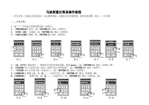
此量仪共有参数设置、线性倍率调整、校正、三大步骤,二.、参数设置:1、按“↑”2秒进入参数设置功能(如图1)。
2、『PROGRAM』程序。
按:『ENTER键』确认(如图2)。
3、『ONE。
CH』①通道。
按:『ENTER键』确认(如图3)。
4、『MEASURE』测量。
按:『ENTER键』确认(如图4)。
图1 图2 图3 图4 图5 图6 图75、『M。
SYST』测量单位(一般情况不更改里面的设置,选择metric)。
按:『ENTER键』确认(如图5、6)。
6、『TOLER+ =』公差带上限(设定:按照产品公差带设置)。
.按:『ENTER键』确认(如图7)。
7、『TOLER - =』公差带下限(设定同上)。
.按:『ENTER键』确认(如图8)。
8、『APPRCH+』报警上限。
设:R。
(关闭不用)。
按:『ENTER键』确认(如图9、10)。
9、『APPRCH-』报警下限。
设:R。
(关闭不用)。
按:『ENTER键』确认(如图11、12)。
图8 图9 图10 图11 图1210、『SCALE』量程选择。
(选择:Auto)即:量仪显示值为每小格0.002mm。
按:『ENTER键』确认(如图13)。
11、『K。
CH。
A』K系数(内径设为+1。
0000)。
与(外径设为-1。
0000)。
按:『ENTER键』确认(如图14)。
12、『ABSOLUT=』名义值:产品的基本尺寸。
按:『ENTER键』确认(如图15)。
13、『MASTER1』大规实测值与基本尺寸之差。
(大规实测值减去名义值)。
按:『ENTER键』确认(如图16)。
图13 图14 图15 图1614、『MASTER2』小规实测值与基本尺寸之差。
(小规实测值减去名义值)。
按:『ENTER键』确认(如图17)。
15、直按“↑”出现『。
』退至测量模式。
注:如果更改参数,程序自动弹出『save』保存提示。
AEM 完整功能电压电流多功能测量器说明书
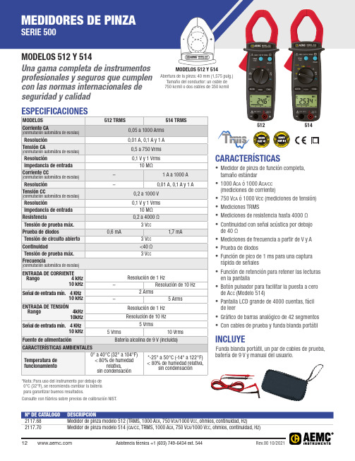
CARACTERÍSTICAS• Medidor de pinza de función completa, tamaño estándar• 1000 A CA ó 1000 A CA/CC (mediciones de corriente)• 750 V CA ó 1000 Vcc (mediciones de tensión)• Mediciones TRMS• Mediciones de resistencia hasta 4000 Ω• Continuidad con señal acústica por debajo de 40 Ω• Mediciones de frecuencia a partir de V y A • Prueba de diodos• Función de pico de 1 ms para una captura rápida de señales• Función de retención para retener las lecturas en la pantalla• Botón pulsador para facilitar la puesta a cero de A CC (Modelo 514)• Pantalla LCD grande de 4000 cuentas, fácil de leer• Gráfico de barras analógico de 42 segmentos • Con cables de prueba y funda blanda portátilMODELOS 512 Y 514Abertura de la pinza: 40 mm (1,575 pulg.) Tamaño del conductor: un cable de 750 kcmil o dos cables de 350 kcmilINCLUYEFunda blanda portátil, un par de cables de prueba, batería de 9 V y manual del usuario.Nº DE CATÁLOGO DESCRIPCIÓN2117.68Medidor de pinza modelo 512 (TRMS, 1000 A ca , 750 V ca /1000 V cc , ohmios, continuidad, Hz)*Nota: Para uso del instrumento por debajo de 0°C (32°F), se recomienda cambiar la batería para garantizar buenos resultados.Consulte con fábrica sobre precios de calibración NIST.MODELOS 512 Y 514Una gama completa de instrumentos profesionales y seguros que cumplen con las normas internacionales de seguridad y calidad 512514*El modelo 566 se encuentra en la sección de Medidores y Sondas Amperimétricas de Corriente de Fuga en la página 83 Consulte con fábrica sobre precios de calibración NIST.。
ua微安ma毫安级自动切换量程电流电压表
ua微安ma毫安级自动切换量程电流电压表
摘要:
一、引言
二、产品概述
三、功能特点
四、应用领域
五、结论
正文:
一、引言
随着科技的快速发展,电流电压测量仪器在各个行业中的应用越来越广泛。
微安级自动切换量程电流电压表作为一种高精度的测量工具,已经在电子、通信、科研等领域发挥着重要作用。
本文将为您详细介绍ua微安ma毫安级自动切换量程电流电压表的产品特点及应用。
二、产品概述
ua微安ma毫安级自动切换量程电流电压表是一种集电流、电压测量功能于一体的仪器。
它采用微安表和毫安表自动切换量程的技术,使得测量范围更广泛,测量结果更为精确。
此外,该产品还具备较高的抗干扰能力和稳定性,适用于各种复杂环境下的测量工作。
三、功能特点
1.自动切换量程:微安表和毫安表自动切换量程,用户无需手动调整,操作简便。
2.高精度:采用先进的测量技术,使得测量结果精确到微安级别。
3.高稳定性:产品具备良好的抗干扰性能,能够在复杂环境下保持稳定工作。
4.广泛测量范围:可测量电流、电压,满足多种测量需求。
四、应用领域
1.电子行业:在电子产品的设计、生产、维修等环节中,对电流电压进行精确测量。
2.通信行业:在通信设备的安装、调试、维护等过程中,对电流电压进行实时监测。
3.科研领域:在实验室中对电流电压进行精确测量,为科研工作提供数据支持。
4.其他行业:还包括电力、医疗、石油化工等领域,对电流电压的测量需求。
五、结论
ua微安ma毫安级自动切换量程电流电压表凭借其优越的产品性能和广泛的测量范围,在各个行业中得到了广泛的应用。
马波斯气动量仪气电转换放大器调整说明书(优选)word资料

马波斯气动量仪气电转换放大器调整说明书(优选)word资料马波斯气动量仪气电转换放大器灵敏度及零位调整操作说明书一、概略各部图示:放大器电源a.灵敏度调节钮(倍率调节钮。
d.放大器进气口。
b.零位调节钮。
e.排气口。
c.放大器出气口(至气测头。
f.电源指示灯。
g.电源开关。
二、测量前准备1.按要求准备好马波斯工作的电源和气源。
(供气压力0.15~0.2Mpa,供气压力恒定,气源干燥无水、无油2.将“灵敏度调节钮”、“零位调节钮”右旋到底(全部关闭。
三、确认当前测量事件对于放大器灵敏度和零位所需要调节的方向,方法如下:1.样件或标准环选用的原则:1.1 要避免样件圆度及锥度不良对测量所造成的误差。
1.2 要尽量按照工艺控制上下限的范围选用样件。
2. 准备好二个已经标定好实际尺寸的产品样件或标准环,按标定值计算出它们的绝对值差如 D1 = V1max-V1min;3. 将两个样件分别放入气动测头,按触摸屏显示值计算出它们的绝对值差如D2 = V2max-V2min;4. 调整方向的确定:如D1 > D2,则“灵敏度调节钮”和“零位调节钮”都要统一向右调节; 如D1 < D2,则“灵敏度调节钮”和“零位调节钮”都要向左调节。
四、内径测量调整举例说明:1. 假定两个产品样件标定值分别为 V1max = -1μm;V2max = -10μm;则 D1 = V1max-V1min = -1-(-10=9μm;那么D = D1/2 = 9/2 = 4.5μm;2.将气动测头放入大尺寸样件,调节“灵敏度调节钮”直至触摸屏显示值 = D= 4.5μm;3.将气动测头放入小尺寸样件,调节“零位调节钮”直至触摸屏显示值 = -D= -4.5μm;4.再将气动测头放入大尺寸样件,调节“灵敏度调节钮”直至触摸屏显示值 =D = 4.5μm;5.再将气动测头放入小尺寸样件,调节“零位调节钮”直至触摸屏显示值 = -D = -4.5μm;6.反复多次直至气动测头放入大尺寸样件显示值= 4.5μm;气动测头放入小尺寸样件显示值 = -4.5μm;7.最后将气动测头放入小尺寸样件,调节“零位调节钮”使显示值 = -10μm即可。
多功能电流电压测量器说明书
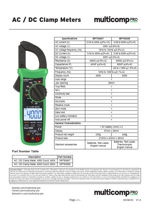
Page <1>V1.005/08/20AC / DC Clamp Meters/multicomp-pro /multicomp-pro/multicomp-proSpecifications MP760607MP760608AC current (A)0.04 to 400A ±(2%+10)0.06 to 600A ±(2%+5)AC voltage (V)600V ±(0.8%+5)AC voltage frequency (Hz)10Hz to 10kHz ±(0.5%+2)DC Current (A)0.04 to 400A ±(2%+5)0.06 to 600A ±(2%+5)DC voltage (V)600V ±(0.5%+2)Resistance (Ω)40MΩ ±(0.8%+2)60MΩ ±(0.8%+2)Capacitance (F)40mF ±(4%+5)60mF ±(4%+5)Temperature (°C)--40 to +1000 ±(1.5%+5)Frequency (Hz)10Hz to 10MHz ±(0.1%+4)Display count 40006000Auto range √Jaw opening 28mm True RMS √NCV√Continuity test √Diode √MAX/MIN √Relative mode √Zero mode √Data hold√Low battery indication √Auto power off√General Characteristics Power 1.5V battery (AAA) x 2Display37mm x 25mmProduct net weight 235g248gProduct size215mm x 63mm x 36mmStandard accessoriesBatteries, Test Leads, English manualBatteries, Test Leads, Thermocouple, English manualImportant Notice : This data sheet and its contents (the “Information”) belong to the members of the AVNET group of companies (the “Group”) or are licensed to it. No licence is granted for the use of it other than for information purposes in connection with the products to which it relates. No licence of any intellectual property rights is granted. The Information is subject to change without notice and replaces all data sheets previously supplied. The Information supplied is believed to be accurate but the Group assumes no responsibility for its accuracy or completeness, any error in or omission from it or for any use made of it. Users of this data sheet should check for themselves the Information and the suitability of the products for their purpose and not make any assumptions based on information included or omitted. Liability for loss or damage resulting from any reliance on the Information or use of it (including liability resulting from negligence or where the Group was aware of the possibility of such loss or damage arising) is excluded. This will not operate to limit or restrict the Group’s liability for death or personal injury resulting from itsnegligence. Multicomp Pro is the registered trademark of Premier Farnell Limited 2019.Part Number TableDescriptionPart Number AC / DC Clamp Meter, 4000 Count, 400A MP760607AC / DC Clamp Meter, 6000 Count, 600AMP760608。
布斯曼电阻器产品说明说明书
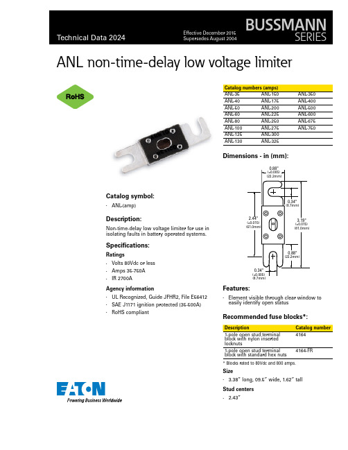
ANL non-time-delay low voltage limiterCatalog symbol:• ANL-(amp)Description:Non-time-delay low voltage limiter for use in isolating faults in battery operated systems. Specifications:Ratings• Volts 80Vdc or less• Amps 35-750A• IR 2700AAgency information• UL Recognized, Guide JFHR2, File E56412• SAE J1171 ignition protected (35-500A)•RoHS compliantANL-35ANL-150ANL-350 ANL-40ANL-175ANL-400 ANL-50ANL-200ANL-500 ANL-60ANL-225ANL-600 ANL-80ANL-250ANL-675 ANL-100ANL-275ANL-750 ANL-125ANL-300ANL-130ANL-325 Dimensions - in (mm):Features:• Element visible through clear window to easily identify open statusRecommended fuse blocks*:block with nylon insertedlocknuts1-pole open stud terminalblock with standard hex nuts4164-FR* Blocks rated to 80Vdc and 800 amps.Size• 3.38” long, 09.5” wide, 1.62” tallStud centers• 2.43”ANL non-time-delay low voltage limiterTechnical Data 2024Effective December 2015Eaton and Bussmann are valuabletrademarks of Eaton in the U.S. and other countries. You are not permitted to use the Eaton trademarks without prior written consent of Eaton.UL is a registered trademark of the Underwriters Laboratories, Inc.Eaton1000 Eaton Boulevard Cleveland, OH Bussmann Division 114 Old State Road Ellisville, MO 63021United States/bussmannseries© 2015 EatonAll Rights Reserved Printed in USAPublication No. 2024 — BU-MC15053December 2015For Eaton’s Bussmann series product information,call 1-855-287-7626 or visit:/bussmannseriesFollow us on social media to get thelatest product and support information.The only controlled copy of this data sheet is the electronic read-only version located on the Eaton network drive. All other copies of this document are by definition uncontrolled. This bulletin is intended to clearly present comprehensive product data and provide technical information that will help the end user with design applications. Eaton reserves the right, without notice, to change design or construction of any products and to discontinue or limit distribution of any products. Eaton also reserves the right to change or update, without notice, any technical information contained in this bulletin. Once a product has been selected, it should be tested by the user in all possible applications.Time-current curves – average melt:10,000101001000CURRENT IN AMPS1001010.10.01T I M E I N S E C O N D SAMP RATING503580100130150200225275325350400500。
电流测量程序使用说明
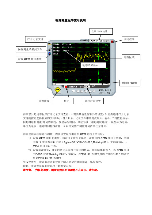
电流测量程序使用说明
如果您只是用本程序打开记录文件查看,不需要其他任何额外的设置,只需要通过打开记录文件的按钮选择相应的文件即可。
打开以后,记录文件中的电流最大,最小,平均值将显示,同时将绘制电流-时间的曲线,横坐标为时间,单位为秒(相对测试开始)。
纵坐标为电流,单位为毫安。
通过时间拖拽滑杆,可以浏览整个测量时间内的任意部分。
如果使用本程序进行测量,需要设置程控电源在GPIB 总线上的地址:
1) 设置GPIB 接口的类型,通过这个按钮选择您正在使用的GPIB 接口卡类型,当前共有3中类型可以支持(Agilent/NI VISA,NI488.2,Keithley488),大部分情况下,VISA 接口可以工作。
2) 设置电源地址,地址的格式必须符合固定的格式,如实际地址为5,当GPIB 接口为VISA 或者Keithley488时,请输入:GPIB0::05::INSTR,如果使用NI488.2则请使用GPIB0::05::96::INSTR.
完成设置后,请在监视时间设置中输入期望的时间间隔,单位为秒。
此时,按开始监视的按钮将开始测量过程。
请注意: 为提高速度,测量开始以后电源将不在显示,请勿动。
动态结果显示。
电流、电压表使用说明书

电流、电压表使用说明书一、第一次使用前的检查:1、检查USB母头中间两个脚是否短路,如果没有短路,手机最大充电电流只有500MA(即进入电脑USB充电模式)。
2、查看表头显示的是哪个状态,如果已经是电流4秒、电压4S交替显示状态,就不需要调。
否则,可先通过按键调到电流电压交换显示状态,再长按此键5S锁定,这样掉电后还是这样显示的,以后无需再调。
3、表头校准,可用户万用表测试显示电压是否有误差,充电器输出一般不低于4.8V;测试X1关屏待机,并且电池电量低于80%的状态下的充电电流是否能达到800MA以上?如果电流未达标,建议按下面的3.2项做判断。
如果确认是表头显示问题,可通过表头上的可调电阻来调节准确度。
二、实际测试:把表头的USB公头插充电器,母头接数据线给手机充电测试,其显示的电流与电压为手机的充电电流与电压。
接具体连接方式见下图。
三、手机各状态的充电电流:3.1娟流充:电池电压约低于3V时,约300MA的娟流充,使电压达到手机软件能启动的电压,约3.5V转为恒流充。
娟流充状态可以忽略,很少达到这个状态。
3.2恒流充:当电池电压在3.5-4.0V之间(约低于90%电量),为恒流充。
其电流大小与以下情况有关:A、是否关屏待机(亮屏使用时会少200MA左右);B、充电设备有关(在电脑上充电时,上限500MA,当手机检测到USB中间两个数据脚为短路状态时,为正常充电,可达到设定充电电流,超过500MA);C、与外部环境温度有关(提示低温,高温时,只有约300MA,达到一定温度停止充电);D、与充电器输出电压有关(从4.9V开始,每下降0.1V,充电电流约减少200MA);E、与数据线阻抗有关:如果数据线阻抗过大,导致线损电压过多,电流会下降,其下降关系与D项相同。
如果满足以上最优条件,各机型恒流充电电流可按如下判断:S7/S7T/E1/E1T/Y3T/Y1/ V2等机型充电都低于700MA,其它机型充电大于700MA。
数字电流夹测量器手册说明书
2. Safety
2-1. InBiblioteka ernational Safely Symbols This symbol, adjacent to a terminal, indicates that, under normal use, hazardous voltages may be present Double insulation
Range
Accuracy (% of reading + digits)
0.1% ~ 99.9% ±1.2% of rdg ±2 dgts
Resolution 0.1%
Sensitivity: <0.5V RMS Pulse width: > 100μs, < 100ms; Overload protection: 300V DC or 300V AC rms
400Ω 4kΩ 40kΩ 400kΩ 4MΩ 40MΩ
Accuracy (% of reading + digits) ±(1.0% + 4d) ±(1.5% + 4d) ±(1.5% + 4d) ±(1.5% + 4d) ±(2.5% + 4d) ±(3.5% + 4d)
Resolution
0.1Ω 1Ω 10Ω 100Ω 1kΩ 10kΩ
n, m, W, M, k
Unit of measure prefixes: nano, milli, micro, mega, and kilo
Continuity test
Diode test
Accuracy (% of reading + digits)
±(3% + 5d)
- 1、下载文档前请自行甄别文档内容的完整性,平台不提供额外的编辑、内容补充、找答案等附加服务。
- 2、"仅部分预览"的文档,不可在线预览部分如存在完整性等问题,可反馈申请退款(可完整预览的文档不适用该条件!)。
- 3、如文档侵犯您的权益,请联系客服反馈,我们会尽快为您处理(人工客服工作时间:9:00-18:30)。
目录安全使用注意事项 (2)1、概要 (3)2、特征 (3)3、装置规格 (3)4、外观图、各部分名称 (4)5、操作方法 (5)6、注意事项 (7)7、维护保养 (7)为了确保您的安全,请在使用该装置前仔细阅读注意事项。
注意事项:1)开封前请先确认外包装有无损伤。
2)确认包装上注明的物品是否齐全。
(如有遗失、损伤,请与销售商联络。
)3)请仔细阅读本说明书后,按要求正确连接装置、线缆等。
4)装置的使用场所要求不可有强电磁波及震动。
5)请使用规格为额定(单相AC100VAC120V 50/60Hz)的电源,此规格以外不~可使用。
6)请不要在容易接触到水或油的场所使用。
7)装置的使用请不要超出其本身的使用范围以外。
8)装置内含有精密的电子部件,请不要拆卸、改造。
9)搬运中请注意不要滑落、撞击等。
10)请不要揭下注意、警告标贴及铭板。
11)为确保测定的精确度,请一年实施一次定期点检12)装置报废处理时,请作为工业废弃物处理。
因未遵守以上注意事项而造成的装置故障及错误使用所引发的问题,我公司概不负责。
1)本体AMS-1070M ……………………………… 1台2)笔式探头……………………………… 2根3)AC插头(AC100V用)……………………………… 1个4)装卡片……………………………… 1个5)使用说明书……………………………… 1本1、概要本装置是数字式电阻焊接测定装置(微欧计)。
可对多点电阻焊机的次级线缆、启动线缆等因劣化引起的直流电阻值的增加情况进行测定。
另外,对提早发现焊机因螺丝松动、拧紧度不够等引起的接触面氧化等异常现象很有帮助。
测定方法采用了“四端子法”,可以忽略测定端子与被测定物之间的接触电阻。
并且,为了实现对微小电阻的高精度测定,装置内部采用了2.5A的高精度低电流回路、微小电压增幅回路、共通电压回路等手段。
采用读取方便的LED数字显示。
2、特征2-1、良否判定存储功能可存储10组上限电阻值。
预先存储测定对象的上限电阻值,可以此作为判定基准,快速确定OK/NG。
2-2、自动启动功能测定探头为自动启动型,现场使用方便简单。
2-3、自动关电节能功能为了节省电池,当停止操作约10分钟以上时,装置自动关电。
3、装置规格CPU : Z80同等品测定显示范围: 0.003 mΩ(3μΩ)~ 19.99 mΩ判定对象范围: 0.003 mΩ(3μΩ)~ 9.999 mΩ精度/相对精度:全量程3/1000以下(0.3%)/绝对精度:全量程1/100以下(1%)基准电流: 2.5A定电流存储功能: 10项目索引显示: 4段红色LED设定:按键开关(设定上限电阻值用)电源:可充电铅蓄电池主体尺寸:参照外形尺寸图附属品:笔式探头(线长3M)充电用AC电源插头(AC100V用)装卡片4、外观图、各部分名称A:选择显示部(Ch) G:设定/存储显示键(SET)B:数据显示部(mΩ) H:模式切换键(MODE)C:信号灯 I:电源开关键(ON/OFF)OK/NG :判定LEDCHARGE:充电显示 J:AC插头连接部(DC IN 12V)EMPTY :电池电量不足显示D:模式指示灯MEASURE:测定模式SET :设定模式E:选择键↑:通道(Ch)切换数值增↓:通道(Ch)切换数值减F:设定键↑:闪烁段的数值增↓:闪烁段的数值减→:闪烁段的移动5、操作方法5-1、测定方法①将测定探头安装到主体上。
按电源开关键(POWER)的[ON/OFF]。
测定数据显示部会显示[0.000],[模式指示灯]的MEASURE(绿)亮灯。
接通电源后即为测定模式。
②设定电阻值的上限值时,按选择键[↑][↓]来选择您需要的编号。
上限值可存储设定0~9组。
按[↑]键,Ch显示部的数值会以1为单位增加。
按[↓]键,Ch显示部的数值会以1为单位减少。
③用力将探头的先端按在测定对象物上。
自动开始测定,在[数据显示部]会显示出测定结果的电阻值。
※当所测电阻值在设定值以下的场合,蜂鸣器会发出一声短音(噼),[信号灯]的OK(LED)会亮灯。
※当所测电阻值超出设定值的场合,蜂鸣器会发出五声短音(噼噼噼噼噼),[信号灯]的NG(LED)会亮灯。
※测定过程中,如探头与测定物分离而不能正确测定的场合,[数据显示部]会显示[- - - -]并判定为NG。
※当电阻值超出测定显示范围的场合,会显示[- O. F.-]判定为NG。
接着进行另一次测定的场合,从上述的②项开始反复操作即可。
5-2、上限电阻值的设定方法(存储设定)通过设定测定对象物的上限电阻值,即可对测定值进行NG判定。
上限电阻值可设定记忆0~9 Ch 10组。
①按模式切换键[MODE],即可从测定模式[MEASURE](绿灯亮)切换成设定模式[SET](黄灯亮)。
※按此键即可反复切换模式。
②按选择键选择需要的编号。
按[↑]键,Ch显示部的数值会以1为单位增加。
按[↓]键,Ch显示部的数值会以1为单位减少。
※每显示一个编号(0~9 Ch),设定上限电阻值会在[数据显示部]显示。
③可变更[数据显示部]闪烁字段的数值。
闪烁字段利用[定位开关]的[→]键移动。
利用[↑][↓]键变更数值。
[→]:闪烁字段的移动[↑]:闪烁字段的数值增[↓]:闪烁字段的数值减④变更上限电阻值设定后,按[设定/存储显示键](SET键),记忆变更后的新设定值。
※请注意此时若忘记按[SET]键,变更后的数值就不会被记忆。
5-3、上限电阻值内容确认方法(存储确认)①在测定模式(MEASURE 绿灯亮灯时)的状态下,利用选择键[↑][↓]来选择您想要确认的存储Ch。
②按[设定/存储显示键][(SET键],设定的上限电阻值就会在[数据显示部]显示,即可确认。
※确认其他设定内容的场合,反复操作①②项即可。
5-4、有关充电电池电池电压下降到其下限值,信号灯[ENPTY]LED就会亮灯,蜂鸣器会发出一声长音、3声短音(噼—·噼噼噼),然后自动切断电源。
此时,请及时将AC电源插头插入主体充电。
充电过程中,信号灯[CHARGE]LED亮灯。
※电池的电量快充满的时候,充电LED会逐渐变暗。
※即使是报警LED没有亮灯,也请养成每次测定结束后都充电的习惯。
如此则可延长内置电池的使用寿命。
※充电时请务必使用附属品的AC电源插头。
其他的AC电源插头的容量及极性与其可能会有所不同,会引起机械故障破损,请不要使用。
5-5、自动关电功能为了减少内置充电电池的消耗,操作结束后电源仍在接通状态或忘记关掉电源的场合,约10分钟后蜂鸣器会发出三声长音(噼—噼—噼—),然后自动切断电源。
6、注意事项接通电源的同时,如果蜂鸣器发出一次声音,则表明存储的数据损坏了,因此,建议在测定前确认一下存储的数据。
※发生下述(1)~(3)的情况,可能会造成数据损坏。
(1)长时间放置不充电的场合。
(2)不充电,电池电量用尽后。
(3)更换电池后。
7、维护保养本公司的产品虽然均经过调整·检查后才出货的,但仍避免不了产品特性方面故障的发生,因此请允许我们为您提供如下的售后服务。
请阅读以下内容,并在发生故障的场合按其对应。
本产品是精密的检测仪器。
为了能够保持其准确的测定精度,请定期实施校正点检。
【保修期间】(1)本公司产品出货后1年内,在正确使用状态下发生故障及问题的场合,原则上在我公司工场无偿为您修理·再调整。
但是,为修理或点检而运送到我公司的单程运费和包装费等由客户承担。
(2)修理或点检作业通常在我公司受理日起14日内完成。
但是,修理所需配件等有特殊交货期的场合除外。
(3)修理或点检作业通常在我公司的服务工场进行。
但是,根据客户的使用状况希望出差修理、点检的场合,请事先与我公司营业部联络。
(4)由于使用者的操作方法错误、擅自改造产品及过度污损(油、酸、灰、砂)等由使用者的责任引起的故障,即使是在1年以内的保修期也是有偿修理,客户除了要承担我公司规定的费用(技术费、部件费、人工费)外,还要承担往返运输费和捆包费。
有关修理作业内容,会提出修理明细报告书。
【保修期间外】(1)产品出货超过1年后发生的故障及问题,不管是什么原因造成的,进行修理或点检作业时,需支付我公司规定的费用(技术费、部件费、人工费)。
这种场合与保修期间内一样,修理或点检作业在我公司的服务工场进行,发生的修理品运输费和捆包费等由客户承担。
(2)修理时间与保修期间内的修理时间相同。
(3)客户需要出差修理、点检的场合,请与我公司营业部联络。
另外,需事先提出报价的场合,请客户指示。
判断故障品后,提出报价,取得客户的同意之后进行修理或点检。
※我公司承诺保修规定的内容根据上述记载的期间、条件无偿对应。
此保障期间并不会限制客户在法律方面的权利。
有关超出保修期间的修理等,您若有不清楚的,请与购入的销售商或我公司的营业部联络。
