HB5740_HB4740_智能电流表使用说明书
智能数显电流表说明书
AH1<AL1:区间内报警;AH1=AL1:无报警 AL1>PV>AH1 电继器报警 测量值小于100且大于80时继电器吸和 测量值大于100,或者小于80时,继电器释放
说明: 1、每一个继电器是通过吸和值和释放值的大小关系来确定做上限 (区间外报警)还是下限报警(区间内报警)
二、技术参数:
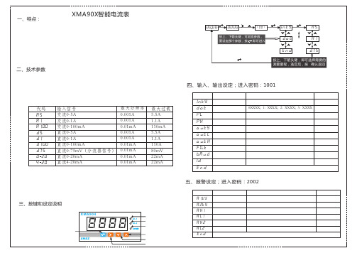
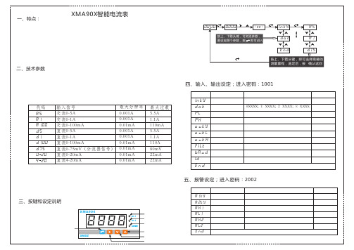
1、工作电源:AC/DC86~265V(DC24V可订货)
2、直流测量精度:0.3%FS; 3、交流测量精度:0.5%FS
四、输入、输出设定;进入密码:1001
4、采样刷新时间:每秒8次 5、测量量程及过载能力
参数符号 参数意义
设定说明
inty 输入信号类型 请参见上文输入信号列表
出厂设定 A5
0.001A
直流0-100mA
0.01mA
直流0-75mV(分流器信号) 0.01mA
直流0-20mA
0.01mA
直流4-20mA
0.01mA
6、交流频率:50Hz/60HZ(其他频率可定制)
5.5A 1.1A 110mA 5.5A 1.1A 110A 80mV 22mA 22mA
pl ph OUTY oUTL OUTH filt baud id end
一、特点:
XMA90X智能电流表
2、参数设定方法
1、第三代智能型电流表以高性能32位ARM单片机为管理核心 2、POWER公司TOP系列电源芯片,保证产品能长期、稳定、可靠工作。
00 00 0000
1 001
inty
a5
3、测量精度高、高速稳定采样,报警响应时间快,可替代电路保护器使用 4、两路继电器报警输出,上限、下限,区间内、区间外报警多种报警方式可选
智能数显电流表说明书
参数符号 参数意义
设定说明
inty 输入信号类型 请参见上文输入信号列表
出厂设定 A5
代码 输入信号
最大分辨率 最大过载
dot 显示量程小数点 0:XXXX;1:XXX.X;2:XX.XX;3:X.XXX 1
A5 A1 A100 D5 D1 D100 D75 0 20 4 20
交流0-5A
0.001A
区间内报警继电器动作规则
AH1<AL1:区间内报警;AH1=AL1:无报警 AL1>PV>AH1 电继器报警 测量值小于100且大于80时继电器吸和 测量值大于100,或者小于80时,继电器释放
说明: 1、每一个继电器是通过吸和值和释放值的大小关系来确定做上限 (区间外报警)还是下限报警(区间内报警)
用户用XMA40X电流表直接测量交流0-150A的电流,配备200A/5A
的电流互感器,把0-150A之间的电流变送输出为4-20mA信号
设定:INTY:A5 DOT:1
PL:0000
PH:2000
OUTY:4 -20 OUPL:000 0 OUTH150 0
区间外报警继电器动作图示
AH1(100)
AL1(80)
报警
报警
报警
区间内报警继电器动作图示
AL1(100)
AH1(80)
报警
报警
区间外报警继电器动作规则
AH1>AL1:区间外报警;AH1=AL1:无报警 PV>AH1或者PV<AL1 电继器报警 测量值大于10或0者,小于80时继电器吸和 测量值小于100且大于80时,电继器释放
交流0-1A
0.001A
交流0-100mA
0.01mA
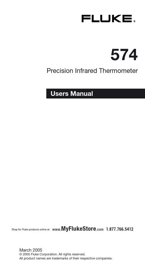
574 精密红外温度计用户手册说明书
574Precision Infrared ThermometerMarch 2005© 2005 Fluke Corporation. All rights reserved. All product names are trademarks of their respective companies.Shop for Fluke products online at: 1.877.766.5412www.MyFlukeStore .com574LIMITED WARRANTY AND LIMITATION OF LIABILITYThis Fluke product will be free from defects in material and workmanship for one year from thedate of purchase. This warranty does not cover fuses, disposable batteries, or damage from accident, neglect, misuse, alteration, contami-nation, or abnormal conditions of operation or handling. Resellers are not authorized to extendany other warranty on Fluke’s behalf. To obtain service during the warranty period, contact your nearest Fluke authorized service center to obtain return authorization information, then send the product to that Service Center with a descriptionof the problem.THIS WARRANTY IS YOUR ONLY REMEDY. NO OTHER WARRANTIES, SUCH AS FITNESS FORA PARTICULAR PURPOSE, ARE EXPRESSEDOR IMPLIED. FLUKE IS NOT LIABLE FOR ANY SPECIAL, INDIRECT, INCIDENTAL OR CONSE-QUENTIAL DAMAGES OR LOSSES, ARISING FROM ANY CAUSE OR THEORY. Since somestates or countries do not allow the exclusion or limitation of an implied warranty or of incidentalor consequential damages, this limitation of liabi-lity may not apply to you.Shop for Fluke products online at: 1.877.766.541223574WarningA Warning identifies conditions and actions that pose ha-zards to the user. To avoid electrical shock or personal injury, follow these guidelines:• Do not point laser directly at eye or indirectly off reflective surfaces.• Before using the thermometer inspect the case. Do not use the thermometer if it appears damaged. Look for cracks or missing plastic.• Replace the batteries as soon as the battery indicator two or less segments.• Do not use the thermometer if it operates abnormally. Protection may be impaired. When in doubt, have the thermometer serviced.• Do not operate the thermometer around explosive gas, vapor, or dust.• Do not connect the optional external probe to liveelectrical circuits.• To avoid a burn hazard, remember that highly reflective objects will result in lower than actual temperature measurements.• Do not use in a manner not specified by this manual or the protection supplied by the equipment may be impaired. CautionTo avoid damaging the thermometer or the equipment under test protect them from the following:• EMF (electro-magnetic fields) from arc welders,induction heaters, etc.• Static electricity• Thermal shock (caused by large or abruptambient temperature changes- allow 30 minutesfor thermometer to stabilize before use).• Do not leave the thermometer on or nearobjects of high temperature.Safety InformationShop for Fluke products online at: 1.877.766.5412www.MyFlukeStore .com4574Table of ContentsIntroduction (5)Warning for the Model 574 NI (6)Symbols and Safety Markings (7)Laser Warning and Serial Number Labels (8)Delivery Content (9)Functions and Display (10)Batteries and Measurement (11)Field of View (12)Spot Size (13)Emissivity - Explanation and Adjust (14)Emissivity - Table and Unknown Value (15)Mode - Maximum and Minimum (16)Mode - Difference and Avarage (17)Probe Connections (18)Setup Alarm (19)Setup - Time and Date (20)Setup - Offset and Min-Max Values (21)Data Logging and Recall (22)Display (23)Display - Man. Range (24)Display - Cycle (25)DIP Switches (26)Troubleshooting (27)Maintenance (28)Emissivity Table (Selected Values) .........................29CE Conformity . (30)Specifications (31)Factory Defaults ....................................................32Shop for Fluke products online at: 1.877.766.5412www.MyFlukeStore .com574 IntroductionThe Fluke Model 574 Infrared Thermometer (the thermometer) is for non-contact temperature measurement. This thermometer determinesan object‘s surface temperature by measuringthe amount of infrared energy radiated by theobject‘s surface.Contacting FlukeTo contact Fluke, call one of the followingtelephone numbers:USA: 1-888-44-FLUKE (1-888-443-5853)Canada: 1-800-36-FLUKE (1-800-363-5853)Europe: +31 402-675-200Japan: +81-3-3434-0181Singapore: +65-738-5655Anywhere in the world: +1-425-446-5500For USA Service: 1-888-99-FLUKE (1-888-993-5853)Or, visit Fluke's Web site at www.fl.To register your product, visit register.fl.Shop for Fluke products online at: 1.877.766.541256574Concerning Factory Mutual ApprovedNonincendive Devices:Operation in Environments that RequireNonincendive DevicesWARNINGIN HAZARDOUS LOCATIONS DO NOT use serial port con-nections, change batteries or open serial port cover. To re-duce risk of explosion in hazardous locations, use only Fluke temp probe part 2432508 and do not use other accessories, such as power supply and cables.A nonincendive rating (NI) indicates that this infrared thermo-meter has been tested to standards for preventing explosi-ons in hazardous areas by limiting the ability of equipment to ignite a specifi ed fl ammable gas or vapor-in-air mixture. Nonincendive equipment is incapable of releasing suffi cient electrical or thermal energy to ignite fl ammable gases or vapors under NORMAL operation and environmental condi-tions.This noncontact thermometer has a Factory Mutual Nonin-cendive rating. The rating from this USA organization reads: “Nonincendive, Class I, Division 2, Groups A, B, C, D; Class I, Zone 2 IIC; T4 Ta = 50ºC when used with 1.5V alkaline batteries.“A Class I, Division 2 location is a location:• where volatile fl ammable liquids or fl ammable gases or vapors exist, but are normally confi ned within closed containers;• where ignitable concentrations of gases, vapors or liquids are normally prevented by positive mechanicalventilation; or• adjacent to a Class I, Division 1 location, where ignitable concentrations might be occasionally communicated• groups A, B, C, D refers to: Acetylene, Hydrogen, Ethylene, and Propane.Warning for the Model 574 NIShop for Fluke products online at: 1.877.766.5412www.MyFlukeStore .com7574 Symbol Explanation Risk of danger. Important information. See Risk of dan Manual.Hazardous voltage. Precedes warning Warning. Laser.Conforms to requirements of European Union and European Free Trade Association (EFTA)°C Celsius°F FahrenheitBattery Symbols and Safety Markings1The laser sight simplifies sighting of the measure-ment object. It shows the spot size that includes the measured target.To turn the laser on or off press the LASER button (K) when the trigger is pulled. A laser symbol (1)appears when the laser is on. The laser automaticallyturns off if you release the trigger.LASERK 1Shop for Fluke products online at: 1.877.766.5412www.MyFlukeStore .com574Laser Warning and Serial Number Labels89574• The unit• Getting Started• Two AA batteries• Manual on CD• Thermocouple type K probe• Windows-based software on CD• RS232 cable • Power supply Delivery Content Shop for Fluke products online at: 1.877.766.5412www.MyFlukeStore .com10574Functions and Display Function keys and display:(A)Visual and audible alarm (B)Display (C)Up and Down keys (D)Enter (E)Handle and battery compartment (DIP switches for adjustments are inside handle)(F)Trigger (G)Tripod mount (H)6 main function keys FUNCTIONSUSER INTERFACEDisplayed functions:(1)Laser condition /Lock symbol (2)Time (or date)(3)Main temperature display (4)Graphic display (5)Emissivity value (6)Status bar (7)Mode indicator (8)Battery life indicator (9)MAX, MIN, DIF, AVG symbols DISPLAYA B C D E F G H 123456789Shop for Fluke products online at: 1.877.766.5412www.MyFlukeStore .comBatteries and MeasurementTo open the battery compartment, press gently on the top part of the handle to release the catch and pivot the grip as shown in thefigure. Orient the batteries (two alkaline R6 (AA,UM3)) positive side up as shown on the housing.To take a temperature measurement, hold the unit as shown. Aim at the target. Pull the trigger (F).The temperature of the object being measured is shown on the display (B). The temperature will be displayed for seven seconds after trigger is released.MEASUREMENT MEASUREMENTShop for Fluke products online at: 1.877.766.5412www.MyFlukeStore .comField of ViewMake sure that the target is larger than the unit’s spot size. The smaller the target, the closer you should be to it.Shop for Fluke products online at: 1.877.766.5412STANDARD MODELOptical ChartFOCUS POINT D:S = 60:1 FAR FIELD D:S = 35:1CLOSE FOCUS MODELOptical ChartFOCUS POINT D:S = 50:1 FAR FIELD D:S = 12:1The measured spot size depends on the dis-tance between the object you are measuring and the infrared thermometer.The relationship between distance and spot sizeis 60:1(Standard Focus) or 50:1 (Close Focus) at the focus point. The D:S in the far field (>33ft/10m) is 35:1 (Standard) or 12:1 (Close Focus). Spot SizeShop for Fluke products online at: 1.877.766.5412Emissivity - Explanation and AdjustReflected energyEmitted energyT ransmitted energyEMISSIVITYT argetThe amount of infrared energy radiated by an object depends on its emissivity and its temperature.The emissivity depends on the material and its surface characteristics. For more accurate readings, adjust the emissivity value for the type of material being measured.To adjust the emissivity value, press EMISS (P).Use the Up and Down keys to select “Free“(“Free(“Free” will have a flashing underline) (7).Press EMISS again.“Free” is not underlined,and the emissivity icon (5)flashes. Use the Up and Down keys (C) to adjust.Press ENTER (D) to activate this setting.EMISSIVITYADJUST EMISSIVITYP57CDShop for Fluke products online at:1.877.766.5412www.MyFlukeStore .comEmissivity - Table and Unknown ValueTo adjust the unit’To aT s emissivity value for a material with unknown emissivity, plug in the probe.Pull the unit’s trigger.Place the measuring tip of the probe on the area to be measured.Wait for the reading to stabilize.P75CDNote the indicated probe temperature reading.Release the trigger. Pull the trigger again. Measure the same area using infrared measurement. Press the emissivity button (P). Use the Up and Down keys (C) to select the material name “Free” which will be shown in the display (7). Press the emissivity button (P) again until the emissivity sign (5) flashes. Use the arrow keys (C) to change the emissivity value until the temperature matches the probe’s reading.UNKNOWN VALUETo choose the emissivity of a material, press EMISS (P). The display shows a material name (7), an emissivity value,and the calculatedtemperature value (5). To choose another material,use the Up and Down keys (C). Press ENTER (D) to activate this setting.TABLE OF VALUESTAB T Shop for Fluke products online at: 1.877.766.5412www.MyFlukeStore .comMode - Maximum and MinimumO To activate the MAX mode,press MODE (O) until the MAX symbol appears (9).The measured maximum temperature is displayed (3) as long as the trigger is pulled or locked on. The real time temperature is shown in the lower part of the display (NORM) (7).MAXIMUMTo activate the MIN mode,press MODE (O) until theMIN symbol (9) appears.The measured minimumtemperature (3) isdisplayed as long as the trigger is pulled or locked on.The real time temperature is shown in the lower partof the display (NORM) (7).MODEMINIMUMO937MAX937MINShop for Fluke products online at: 1.877.766.5412www.MyFlukeStore .comMode - Difference and AvarageO37AVG9 To activate the AVG mode,press MODE (O) until theAVG symbol (9) appears.The average value ofmeasured temperatures(3) is displayed as longas the trigger is pulled orlocked on. The real timetemperature is shown inthe lower part of thedisplay (NORM) (7).To activate the DIF mode,press MODE (O) until theDIF symbol (9) appears.The difference betweenthe measured max andmin temperatures isdisplayed (3) as long asthe trigger is pulled orlocked on. The real timetemperature is shown inthe lower part of thedisplay (NORM) (7).3O97DIF AVERAGEDIFFERENCEShop for Fluke products online at: 1.877.766.5412Probe Connections121011Open the battery compart-ment and set the switches ON or Off according to the desired probe type.(10) NTC - thermistor (11) TC - thermocouple (12) Thermocouple type J (13) Thermocouple type KPROBECONNECTIONS13Connect the probe to the input (U). Press MODE,until the desired probe symbol (7) appears. The probe temperature isshown in the lower part of the display (6). The real time infrared temperature is shown in the maindisplay (3).U763Shop for Fluke products online at:1.877.766.5412www.MyFlukeStore .comSetup AlarmNA 6D CThe low alarm (LoAl)generates an audible andvisual (flashing LED (A)and laser) alarm if thetemperature is below the setpoint. To set the alarm value (6), Press SETUP (N) twice and use the Up and Down keys (C).Then press ENTER (D)to activate this setpoint.NA 6CDThe high alarm (HiAl) generates an audible and visual (flashing LED (A)and laser) alarm if the temperature is above the setpoint.To set the alarm value (6),Press SETUP (N) once,and use the Up and Down keys (C).Then press ENTER (D) to activate this setpoint.HIGH ALARMLOW ALARMShop for Fluke products online at: 1.877.766.5412www.MyFlukeStore .comSetup - Time and DateTo set the time, press SETUP (N) three times.Change the time (2)using the Up and Down keys (C).Then press ENTER (D)for each time segment to activate this time setting.The time appears on the display and is stored within the data logger .TIMEN2CDNDATETo set the date, press SETUP (N) four times.Change the date using the Up and Down keys (C).Then press ENTER (D) for each date segment to activate this date setting.The date (2) is stored within the data logger .2DCShop for Fluke products online at:1.877.766.5412www.MyFlukeStore .comSetup - Offset and Min-Max ValuesMODEMAXMINDIFAVGTC/NTCMIN-MAXO6N D C confirm. The OFFSET feature allows the temperature values for several units to be matched, correcting for the allowed temperature tolerance difference between units. The OFFSET function can also be used toincrease the accuracy for a narrow temperature range.This function is used with a selected emissivity to add or subtract an offset value (±10°C/±18°F) to thetemperature value. Press the Setup button (N) until "Offset" appears in thedisplay. With the arrowkeys (C) adjust the displayto the corrected value.Press ENTER (D) toOFFSETTo show the minimum To sT and maximumtemperature values dur-ing a measurement at the bottom of the display,press MODE (O) until the two values appear (6).MIN-MAX VALUES X VALMIN-MAX V MODEShop for Fluke products online at:1.877.766.5412www.MyFlukeStore .comData Logging and RecallHOW TO STORE DATATo Recall stored data,To RT press the ENTER button (D), without pulling the trigger. Then press the DATA button (M) until RCL appears on the display. A log location will be shown(6).To select another log loca-tion, use the Up and Down keys (C).DAT DA ATA T RECALLM 6D C By pressing the ENTER button (D) the LOG function (6) appears on the display. Pull the trigger (F) and hold it. Aim at the target. Be sure that the laser sighting is inside the target. Gently release the trigger to record the temperature. The next location will be shown on the display.This function is also initiat-ed by pressing the DATA button (M) once.D6FM Shop for Fluke products online at: 1.877.766.5412www.MyFlukeStore .comDisplayLC The graphic display (4)shows the temperature asa picture. The last tenmeasurements are shown(B). It is possible to choosebetween Auto Range andManual Range. In manualrange the user defines thebeginning and endingtemperature points of thegraph.B4 Press DISPLAYLAYPress DISPLA(L) once.Use the Up and Downkeys (C) to toggle betweenranges. Auto Range isautomatically defined bythe measured maximumand minimum value.Manual Range (ManRange) is user defined(see DISPLAY, BEGINLAY,(see DISPLAsection).GRAPHIC DISPLAYAUTO OR MAN RANGEShop for Fluke products online at: 1.877.766.5412Display - Man. RangeTo set the BEGIN value for the graphic display (Man Range is activated),press DISPLAY (L) until “Begin” is shown at the status bar. Use the Up and Down keys (C) to select the value (6).DISPLAYBEGIN(Man. Range)LC6DISPLAYEND(Man. Range)To set the END value of the graphic display (Man.Range), press DISPLAY LAY Range), press DISPLA (L) until ”End” is shown at the status bar. Use the Up and Down keys (C) to select the value (6).LC6Shop for Fluke products online at:1.877.766.5412www.MyFlukeStore .comDisplay - CycleLC7CYCLE allows the adjustment of the display interval.Press DISPLAY (L)until Cycl.: (7) is shown at the status bar. To select the interval time, use the Up and Down keys (C). The default value is pre-set for 0.2 sec.Shop for Fluke products online at:1.877.766.5412www.MyFlukeStore .comDIP SwitchesBacklight:Backlight On or Off.Set Default:Activates the factory defaultsby overwriting listed settings (see specifications).Ltd. Access:No function buttons will serflash:The laser flashes in case ofover- or underranging of the alarm values.Lock C/ F Digi/Ana Laserflash Ltd. Access Set Default Backlight Buzzer TC-J/TC-KNTC/TC Time/Date Printer Factory Defaults�DIP-Switch Settings�Lock:°C/°F:ch Buzzer:Digi/Ana:Digital or Analog output.Time/Date:Time or date shown on the display.Trigger locked(on) orunlocked (off).:changes between °C and °F and date and time format.Audible alarm On or Off.Change the setting in the unit by using the DIP switches located in the battery compartment (see BATTERIES section).BATT BA NTC/TC:Thermistor (NTC) or thermocouple (TC).TC-J/TC-K:Type of thermocouples.Shop for Fluke products online at:1.877.766.5412www.MyFlukeStore .comTroubleshootingCode Problem Action-O-Target temp. is over Select target-U-or under range within unit’s specs EEPROM-Err EEPROM error Contact factory CalAreaErr Calibration errors Contact factory ProbCalErrBattery icon Battery is low Replace batteries flashes orLowBatt onStatus lineBlank display Battery is dead Replace batteries Laser won’t Low or dead battery Replace batteriesworkAmbient above 45°C Operate unit in 45°C(113°F)(113°F) ambient orbelowShop for Fluke products online at: 1.877.766.5412MaintenanceLens Cleaning:Blow off loose particlesusing clean compressedair. Brush remaining de-bris away with a camel’shair brush.Wipe the surface with amoist cotton swab. Theswab may be moistenedwith water or a waterbased glass cleaner.NOTE: DO NOT use sol-vents to clean theplastic lens.Cleaning the Housing:To clean the exteriorhousing, use soap andwater or a mild commer-cial cleaner. Wipe with adamp sponge or soft rag.Shop for Fluke products online at: 1.877.766.5412Emissivity Table (Selected Values)Aluminum*0.30Asbesto 0.95Asphalt 0.95Basalt 0.70Brass*0.50Brick 0.90Carbon 0.85Ceramic 0.95Concrete 0.95Copper*0.95Dirt0.94Frozen food, 0.90Hot food 0.93Glass (plate)0.85Ice 0.98Iron* 0.70Lead* 0.50Limestone 0.98Oil 0.94Paint 0.93Paper 0.95Plastic** 0.95Rubber 0.95Sand 0.90Skin 0.98Snow 0.90Steel* 0.80Textiles Text T 0.94Water 0.93Wood***0.94*oxidized** opaque, over 20 mils *** naturalShop for Fluke products online at:1.877.766.5412www.MyFlukeStore .comCE ConformityThis instrument conforms to the following standards:EMC: - EN 61326-1:1997+A1:1998+A2:2001 Safety: - EN 61010-1:2001- EN 60825-1:2001This product herewith complies with the requirements of the EMC Directive89/336/EEC and the Low VoltageDirective 73/23/EEC.This instrument conforms to the Standardsof the European Community.CertificationThe temperature sources used to calibrate this instrument are traceable to the U.S. National Institute of Standards and Technology (NIST)and the Deutscher Kalibrierdienst (DKD). Calibration certificates are available as an option.Shop for Fluke products online at: 1.877.766.5412574 Specifi cationsTemperature Range- 30 to 900°C (- 25 to 1600°F)Display Resolution0.1°C (0.2°F)Accuracy± 0.75% of reading or(Infrared)± 0.75K (± 1,5°F), whichever is greaterat 25°C (77°F) ambient temperature,± 2K (± 4°F) for targetsbelow -5°C (23°F)Ambient derating< 0.05K/K or < 0.05%/K,whichever is greater at+ 25°C (77°F) ± 25K (± 45°F)Optical Resolution60:1 (19mm spot size at 1.15 M.) (Standard Focus)(0.75in. spot size at 3.8 feet)Optical Resolution50:1( 6mm spot size at 0.3 M.) (Close Focus)(0.24in. spot size at 0.98 feet) Accuracy± 2K or ± 0.75%,(Thermocouple K & J)whichever is greaterAccuracy(Thermistor)-30to0°C (-22 to 32°F)± 0.6K0to70°C (32 to 158°F)± 0.4K70to100°C (158 to 212°F)± 1K100to120°C (212 to 248°F)± 1.5KRepeatability± 0.5% of reading or ± 0.5°C (1°F), (Infrared)whichever is greater,± 1°C (± 2°F) for targetsbelow -5°C (23°F)Response Time (95%)250 mSecHot Spot Detection (30%)85 mSecSpectral Range8 to 14 µmAmbient Operating Range0 to 50°C (32 to 122°F)Storage Temperature-20 to 50°C (-4 to 122°F)(without batteries)Analog output 1 mV/°C(°F)Digital Output RS232Shop for Fluke products online at: 1.877.766.54123132574Factory DefaultsPower 2 x 1.5 V Alkaline Type AABattery Life 13 hrs. (50% laser and 50% backlight on)Power supply 7.5 V >200 mA (Using the power supply (External)the display automatically switches on)Dimensions 200 x 170 x 50 mm (7.9 x 6.7 x 2 inches)Tripod Mount1/4”-20 UNCData logger100 pointspre-set with emissivity 0.95Lo-Al:0°C Hi-Al:50°Cadjustable only via Software AccessoryDefaultRange Emissivity/Gain 0.95 0.10 to 1.50 in steps of 0.01Emissivity Table Free 30 materialsMode normal Hi Alarm 50°C (100°F) -30 to 900°C (-25 to 1600°F)Lo Alarm 0°C (32°F) -30 to 900°C (-25 to 1600°F)Offset Adjust 0°C (0°F) -10 to 10°C (-18 to 18°F)Graphic Display Auto Range Auto Range / Man Range Cycle Time 0.2 sec0.1 sec to 300 sec Shop for Fluke products online at:1.877.766.5412www.MyFlukeStore .com。
智能电能表说明书

本手册可以在本公司的主页上下载到,同时也提供一些相应的测试软件下 载。
目录
一、YKE□-WH3 智能电度表使用手册…………………………………………1 1、概述…………………………………………………………………………1 2、技术参数……………………………………………………………………1 3、编程和使用…………………………………………………………………2 测量显示……………………………………………………………………2 编程操作……………………………………………………………………6 4、通迅…………………………………………………………………………9 通迅报文举例………………………………………………………………10 MODBUS 地址信息表……………………………………………………10 5、功能输出……………………………………………………………………13
型号
外形尺寸(mm)
测量
显示
辅助功能
YKE120-WH3 YKE96-WH3
120*120*112 96*96*112
有功电能 无功电能 单排 LCD 分 电能脉冲输 总有功功率、总无功功率 页显示 出数字通讯
二、技术参数
输 入 测 量 显 示
电源 输出 安全
网络
电压 电流
额定值 过负荷 功耗 阻抗 精度 额定值 过负荷 功耗 阻抗 精度 频率 功率 电能 显示
主机查询:查询消息帧包括设备地址码、功能码、数据信息码、校验码。地址码表明要选中的从机
智能数显电流表说明书

AL1
NC
NO
COM
345
AL2
NC
NO
COM
678
XMA904(96*48*80)
9 10 11 12 13 14 15 16
A+
B-
5A 1A 100mA 75mV COM
九:设定说明
用户用XMA90X电流表直接测量直流0-2A的电流
设定:INTY:D5 DOT:3
PL:0000
PH:5000
000.0 500.0 4-20 000.0 500.0 01 9600 001
7、变送输出:0~20mA、4~02mA、0~01V 8、通讯规则:RS485(RTU协议)
五、报警设定;进入密码:2002
9、继电器触点:AC250V A 7 10、工作温度:-10~50℃
参数符号 参数意义
设定说明
出厂设定
代码 disp
f END
输入信号 报警延时 测量交流电流频率 退出标志,无需设定
设定范围 0-60秒 50、60
八:接线方式
AC220V
~
12
AL1
AL2 mA-
NO
NO
COM
3456
XMA902(48*48*100)
7 8 9 10 11 12
mA+ 5A 1A 100mA 75mV COM
AC220V ~
一、特点:
XMA90X智能电流表
2、参数设定方法
1、第三代智能型电流表以高性能32位ARM单片机为管理核心 2、POWER公司TOP系列电源芯片,保证产品能长期、稳定、可靠工作。
00 00 0000
1 001
inty
三相三四线智能电能表使用说明指导书
三相三四线智能电能表使用说明指导书1 综合介绍1.1 概述DSZ331/DTZ341三相三线/三相四线智能电能表是威胜集团有限公司研制生产的新一代智能型高科技电能计量产品,符合GB/T17215.321-2008、GB/T17215.322-2008、GB/T17215.323-2008 和DL/T614-2007 等电能表有关标准,采用DL/T645-2007通信规约(有扩展)。
1.2 工作原理简述本产品由电流互感器、集成计量芯片、微控制器、温补实时时钟、数据接口设备和人机接口设备组成。
集成计量芯片将来自电压分压,电流互感器的模拟信号转换为数字信号,并对其进行数字积分运算,从而精确地获得有功电能和无功电能,微控制器依据相应费率和需量等要求对数据进行处理。
其结果保存在数据存储器中,并随时向外部接口提供信息和进行数据交换,其原理框图如图1所示。
拟制:扶小飞2011-06-24 图号:OKRW2.702.635SS审核:拟 制: 扶小飞 2011-06-24 图 号:OKRW2.702.635SS 审 核:L C D 显示器Ia+Ia-Ib+Ib-Ic+Ic-仪用电流互感器(CT)ia-ia+ib-ib+ic-ic+ 微控制器Ua Ub Uo Uc Uo 电压分压电路Uo uauo uo uoubuc 通信接口内部存储器时钟/电池脉冲输出按钮集成计量芯片停电抄表电池电源aU bU U U c n图1:工作原理简述(以三相四线表为例)1.3 技术参数1.3.1 主要技术参数项目 技术要求参比电压 3×220V/380V ,3×57.7V /100V , 3×100V电压测量范围 三相80%Un ~120%Un电流测量范围 1%Ib~6Ib互感器接入式:0.3(1.2)A,1(2)A,1.5(6)A, 5(6)A直通式:5(20)A,10(40)A,拟 制: 扶小飞 2011-06-24 图 号:OKRW2.702.635SS 审 核:15(60)A,20(80)A具体电流规格参见面板标识准确度等级 有功0.2S 、0.5S 级、1级 ; 无功2级工作温度 -25℃~60℃极限工作温度-40℃~70℃相对湿度 ≤95%(无凝露)频率范围 (50±2.5)Hz启动电流 互感器接入式表:1‰In(0.2s 级),1‰In(0.5s 级),2‰In(1级)直通表:4‰Ib(1级)功耗 <1.5W ,6VAMTBF ≥1×10⁵ h设计寿命 10年拟 制: 扶小飞 2011-06-24 图 号:OKRW2.702.635SS 审 核:1.3.2 日历时钟 (DS3231SN 温补时钟) 时钟误差 ≤0.5 s/d (0℃~+40℃时:±2ppm;-40℃~+85℃时:±3.5ppm )时钟频率 1Hz电池寿命 10年电池连续工作时间≥5年1.3.3 光耦脉冲输出脉冲输出常数 出厂设置以仪表面板标识为准。
NHR-5740系列四回路数字显示控制仪使用说明书(130601)

版本号:5740-130601NHR-5740系列四回路数字显示控制仪使用说明书一、概述NHR-5740系列四回路数字显示控制仪采用了表面贴装工艺,全自动贴片机生产,具有很强的抗干扰能力。
本仪表支持多种信号类型输入,可与各类传感器、变送器配套使用,实现对温度、压力、液位、速度、力等物理量的测量显示,可同时显示四路测量信号,可带8路分别报警输出或4路分别变送输出功能、RS485/232通讯等输出功能,适用于需要进行多测量点检测的系统。
二、技术参数三、仪表的面板及显示功能12)开机显示画面:a 、显示全8,指示灯全亮:b、仪表型号和版本号:c、四路信号类型-----第1,2路输入类型-----第3,4路输入类型d、四路测量值-----第1,2路测量值-----第3,4路测量值3)面板指示灯AL1:第一报警指示灯AL2:第二报警指示灯AL3:第三报警指示灯AL4:第四报警指示灯AL5:第五报警指示灯AL6:第六报警指示灯AL7:第七报警指示灯AL8:第八报警指示灯5)标准配线仪表在现场布线注意事项:PV输入(过程输入)1. 减小电气干扰,低压直流信号和传感器输入的连线应远离强电走线。
如果做不到应采用屏蔽导线,并在一点接地。
2. 在传感器与端子之间接入的任何装置,都有可能由于电阻或漏流而影响测量精度。
热偶或高温计输入应采用与热偶对应的补偿导线作为延长线,最好有屏蔽。
RTD(铂电阻)输入三根导线的电阻必须相同,导线电阻不能超过15Ω。
四、通电设置仪表接通电源后进入自检,自检完毕后,仪表自动转入工作状态,在工作状态下,按压键显示LOC,LOC参数设置如下:1. 1)Loc等于任意参数可进入一级菜单(LOC=00;132时无禁锁);2)Loc=132,按压键4秒可进入二级菜单;3)Loc=130,按压键4秒可进入时间设置菜单,对于带打印功能的表;4)Loc等于其它值,按压键4秒退出到测量画面。
2.如果Loc=577,在Loc 菜单下,同时按住键和键达4秒,可以将仪表的所有参数恢复到出厂默认设置。
HB404智能电流表

HB404智能电流表产品概述HB404智能电流表是一种基于数字嵌入式技术的现代化电流检测仪器,适用于各种交流电路中电流的测量和显示。
该仪器具有高精度、可靠性高、易于操作的特点,并且还具有超负荷保护、防雷击、防误操作等安全保护措施。
产品特点1.数字直流电流检测技术:采用先进的数字直流电流检测技术,保证了电流的精确测量和显示。
2.超负荷保护:设备内置超负荷保护模块,当电流超过仪器额定电流范围时,自动切断电路,保护仪器和被测电路的安全。
3.防雷击:具有强大的防雷击功能,在雷击时可自动切断电路,确保仪器的安全。
4.显示清晰:采用大屏幕液晶显示器,可以清晰直观地显示电流值,让用户一看便知。
5.便于携带:体积小巧,重量轻,可随时携带,方便用户进行移动测量。
产品规格•电流范围:0~200A•分辨率:0.1A•显示方式:液晶屏显示•频率范围:50~60Hz•精度:±1.5%•外观尺寸:150mm85mm35mm•重量:约0.3kg应用领域HB404智能电流表广泛应用于电力、石油、化工、建筑、轨道交通等领域,用于测量各种电路中的直流电流值。
它也可以用于火车、汽车、电机等设备的电流检测。
使用方法1.按下电源开关,仪器开始运行。
2.将被测电路的电流线穿过表夹,仪器开始检测电流。
3.显示屏上将出现被测电路中的电流值。
4.测量结束后,按下电源关闭键,关闭仪器。
注意事项1.HB404智能电流表只能测量直流电流。
2.测量时,应保证电流计回路正常接通,以免影响检测精度。
3.测量过程中,应避免仪器在强磁场和强电场下使用,以免出现电磁干扰。
如果必须在强磁场和强电场下使用,应注意加入屏蔽措施。
4.测量时切勿使用过大电流进行测量。
5.在使用过程中,如需清洁仪器,请使用干布进行擦拭,切勿使用湿布或液体清洁。
总结HB404智能电流表是一款功能强大、实用性强、操作便捷的电流检测仪器。
该仪器采用数字直流电流检测技术,保证了电流的精确测量和显示,还具有超负荷保护、防雷击等安全保护措施。
nhr5740系列四回路数字显示控制仪使用说明书(130601)
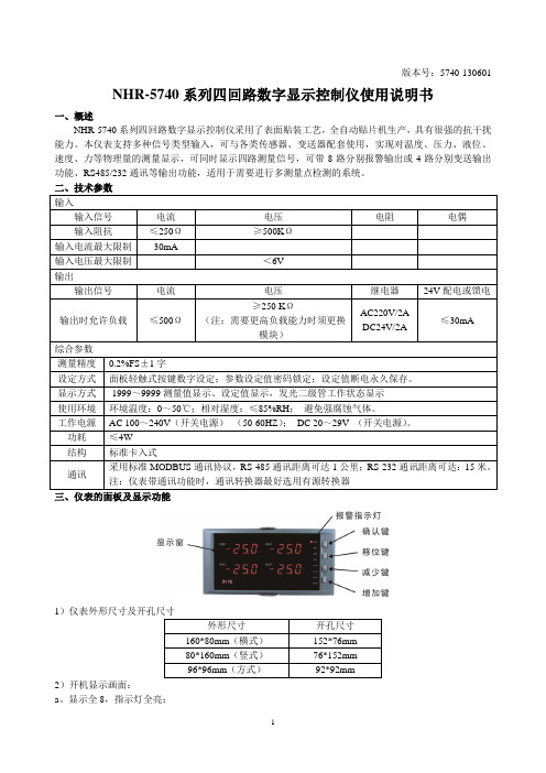
版本号:5740-130601NHR-5740系列四回路数字显示控制仪使用说明书一、概述NHR-5740系列四回路数字显示控制仪采用了表面贴装工艺,全自动贴片机生产,具有很强的抗干扰能力。
本仪表支持多种信号类型输入,可与各类传感器、变送器配套使用,实现对温度、压力、液位、速度、力等物理量的测量显示,可同时显示四路测量信号,可带8路分别报警输出或4路分别变送输出功能、RS485/232通讯等输出功能,适用于需要进行多测量点检测的系统。
二、技术参数三、仪表的面板及显示功能12)开机显示画面:a 、显示全8,指示灯全亮:b、仪表型号和版本号:c、四路信号类型-----第1,2路输入类型-----第3,4路输入类型d、四路测量值-----第1,2路测量值-----第3,4路测量值3)面板指示灯AL1:第一报警指示灯AL2:第二报警指示灯AL3:第三报警指示灯AL4:第四报警指示灯AL5:第五报警指示灯AL6:第六报警指示灯AL7:第七报警指示灯AL8:第八报警指示灯5)标准配线仪表在现场布线注意事项:PV输入(过程输入)1. 减小电气干扰,低压直流信号和传感器输入的连线应远离强电走线。
如果做不到应采用屏蔽导线,并在一点接地。
2. 在传感器与端子之间接入的任何装置,都有可能由于电阻或漏流而影响测量精度。
热偶或高温计输入应采用与热偶对应的补偿导线作为延长线,最好有屏蔽。
RTD(铂电阻)输入三根导线的电阻必须相同,导线电阻不能超过15Ω。
四、通电设置仪表接通电源后进入自检,自检完毕后,仪表自动转入工作状态,在工作状态下,按压键显示LOC,LOC参数设置如下:1. 1)Loc等于任意参数可进入一级菜单(LOC=00;132时无禁锁);2)Loc=132,按压键4秒可进入二级菜单;3)Loc=130,按压键4秒可进入时间设置菜单,对于带打印功能的表;4)Loc等于其它值,按压键4秒退出到测量画面。
2.如果Loc=577,在Loc 菜单下,同时按住键和键达4秒,可以将仪表的所有参数恢复到出厂默认设置。
单相智能电能表说明书
目录一、产品简介 (1)1.1 概述 (1)1.2 规格和主要参数 (1)二、外形说明及安装 (3)2.1 液晶显示及内容 (3)2.2 电表的安装及接线 (5)三、功能说明 (8)3.1 计量功能 (8)3.2 费控功能.......................................................................................................... 错误!未定义书签。
3.3 测量及监测 (8)3.4 事件记录 (8)3.5 费率、时段 (9)3.6 显示功能 (9)3.7 报警功能 (9)3.8 冻结功能 (9)3.9 计时功能 (10)3.10 脉冲输出 (10)3.11 通信接口 (10)四. 工作原理 (10)五、安装............................................................................................................................ 错误!未定义书签。
六、运输与贮存................................................................................................................ 错误!未定义书签。
七、质保期限.................................................................................................................... 错误!未定义书签。
一、产品简介1.1 概述单相智能电能表是本公司研制生产的新一代电能计量产品。
本产品采用专用大规模集成电路和SMT生产工艺,具有电能计量、数据处理、实时监测、自动控制、信息交互等功能。
三相四线费控智能电能表使用说明书
三相四线费控智能电能表使用说明书DTZY22-Z 型三相四线费控智能电能表采用当今最先进的电能表专用集成电路、永久保存信息的不挥发性存贮器、红外通讯、汉字大画面液晶显示等多项技术。
该表集众多功能于一体,实现了有功、无功双向分时电能计量、分相双向计量、需量计量、功率因数计量、显示和远传实时电压、电流、功率等,并实现用户的预付费功能,又可灵活预置多种功能:超负荷报警和自动断电、缺相报警、缺相情况记录、自动抄表等。
以手持电脑为媒介实现用户与供电部门计算机的信息传输。
本表还具有双RS485 接口,方便电力部门实现计算机网络管理。
并采用多种软件、硬件抗干扰措施,保证电表可靠运行,从而适应了电力部门对用户有效及时地现代化科学管理需求。
1.1、性能 1.1.1、电能表的线路设计和元器件的选择以较大的环境允差为依据,因此可保证整机长期稳定工作。
精度基本不受频率,温度、电压变化影响。
整机体积小,重量轻,密封性能好,可靠性较其它同类产品有明显提高。
1.1.2、经过严格的安全认证,可通过远程对电能表进行远程拉、合闸控制和时段等参数的设置,进而对用户的用电实施远程管理。
1.1.3、当电源失电后,锂电池作为后备电源,可以保证内部数据不丢失,日历,时钟、时段程序控制功能正常运行,来电后自动投入运行。
在电能表端钮盒上设置有光电耦合脉冲输出接口,以便于进行误差测试和数据采集,脉冲输出常数与标牌标志的表常数一致。
1.1.4、电表运行信息可由手持电脑、RS485 接口两种媒介传输,电力部门可根据本地区具体情况自行选择一种或多种传输方式。
电能表通讯规约符合DL/T645。
三相四线费控智能电能表使用说明书- 4 - 二、原理与主要技术参数:A、B、C 三相电压、电流信号经专用电能表高速集成电路处理转换成相应的数字信息后,计算出各相电压、电流、功率、电能,CPU 中央处理器通过SPI 口读取有关数据量,并通过程序处理求出各总电量、费率电量、需量、功率因素等。
三相智能电能表说明书
计量功能………………………………………………………4
电参量测量功能…………………………………………………6
电压监测功能…………………………………………………7
电网负荷曲线数据记录功能…………………………………7
事件记录功能…………………………………………………8
指示为第Ⅳ象限时,表示当前的有功功率为正向,无功处于第Ⅳ象限。
电压的实时状态通过液晶下方的“电压指示符”(“Ua”、“Ub”、“Uc”)指示,“Ua”指示A相,“Ub”指示B相,“Uc”指示C相。当某相电压正常时,相应相别的“电压指示符”常显;当某相电压断相时,相应相别的“电压指示符”闪烁。
电流的实时状态通过液晶下方的“电流指示符”(“-Ia”、“-Ib”、“-Ic”)指示,每个指示符前面的“-”表示该相电流的方向,“Ia”指示A相,“Ib”指示B相,“Ic”指示C相。当某相有电流时,相应相别的“电流指示符”常显;当某相无电流(严重不平衡)时,相应相别的“电流指示符”闪烁。当某相电流正向时,相应相别的“电流指示符”前面的“-”不显示,当某相电流反向时,相应相别的“电流指示符”前面的“-”显示。
功耗
电压回路:每相≤、6VA;电流回路:每相≤(Ib)
工作/极限温度范围
-25℃~65℃/-40℃~75℃
相对湿度
≤95%(无凝露)
时钟内部电池参数
时钟误差
温补硬时钟,在工作温度范围内,≤d
内部时钟电池
容量:1块锂电池(SAFT/OMNICELL)
外部抄表电池
容量:2块3V锂电池(SAFT/OMNICELL)
1、概述…………………………………………………………………1
电流表的使用

2
火炬实验室·实验说明书
安全警示和注意事项
• 请严格按照电流表使用的注意事项操作。不要损坏电流表。
Work hard. Dream big. Have fun. @TorchLab
3
(6)怎样才能把电流表正确接入电路呢?如图所示的几种错误接法究竟错在哪里?
(7)请按下图连接电路,学习用电流表测量通过灯泡的电流 (请按正确连接电路的规则连接电路:①、连接电路时,开关应断开;②、检查无误后,先用开 关试触,不超量程,在闭合开关;③、读数时,视线要正对电流表表盘。)
Work hard. Dream big. Have fun. @TorchLab
针在这排上所指示的位置读数。
Work hard. Dream big. Have fun. @TorchLab
1
火炬实验室·实验说明书
下图(a):量程 ______A.刻度盘每大格表示______A。每小格表示_______A,指针示数为 ________A。 下图(b):量程 ______A.刻度盘每大格表示______A。每小格表示_______A,指针示数为 ________A。
火炬实验室·实验说明书
用电流表测量电流的大小
类型 级别 难度 目的
基础测量实验 A 初中做实验 认识电流表,会看电流表的说明书,会正确使用电流表测量电路中的电流。
会用电流表测量电路中电流的大小是必备的实验技能,是后续研究电路必备的基础 知识。对照实物,认真学习“j0407型直流电流表说明书”熟悉电流表的使用方法。 通过实验,掌握电流表使用规则,会正确测出电路中电流的大小。
