【都灵理工】电路理论CircuitTheory_Exercise_1
《电路》教学大纲

教学大纲课程编码:05311230课程名称:电路英文名称:Circuit Theory学分:5学时:75(其中:讲课学时:75 分析讨论:0 实验学时:0 上机学时:0)课程内容:“电路”课程是一门研究电路理论、电路分析与综合的基础工程学科,它属于电类以及相关各专业共同的一门主要的技术基础课.课程内容主要包括:电路基本概念和电路定律、电阻电路的等效变换、电阻电路的分析方法、电路定理、动态电路的时域分析、正弦稳态电路的分析、谐振电路、互感电路、三相电路、非正弦周期电流电路、动态电路的复频域分析、电路方程的矩阵形式、二端口网络。
通过学习本门课程,使学生掌握电路理论的基本知识、基本分析计算方法和基本实验技能,为学习后继相关课程准备必要的电路理论知识,为从事工程技术工作、科学研究以及开拓性技术领域打下坚实的基础。
选课对象:自动化、电气工程、电子信息工程、电子信息科学与技术、农业电气化、生物医学工程、机械电子工程、测控技术与仪器、光信息科学与技术、通信工程、建筑电气与智能化等专业的本科学生先修课程:高等数学、工程数学、物理教材:《电路原理》(第2版)陈晓平李长杰主编,机械工业出版社,2011年7月出版电路Circuit Theory课程编号:05311230学分:5学时:75 (其中:讲课学时:75 分析讨论:0 实验学时:0 上机学时:0)先修课程:高等数学、工程数学、大学物理适用专业:自动化、电气工程、电子信息工程、电子信息科学与技术、农业电气化、生物医学工程、机械电子工程、测控技术与仪器、光信息科学与技术、通信工程、建筑电气与智能化等专业教材:《电路原理》(第2版)陈晓平李长杰主编,机械工业出版社,2011年7月出版开课学院:电气信息工程学院一、课程的性质与任务《电路原理》课程是一门研究电路理论、电路分析与综合的基础工程学科,它属于电类以及相关各专业共同的一门主要的技术基础课。
本课程是电类专业以及相近专业的入门课。
《电路理论》课程教学大纲
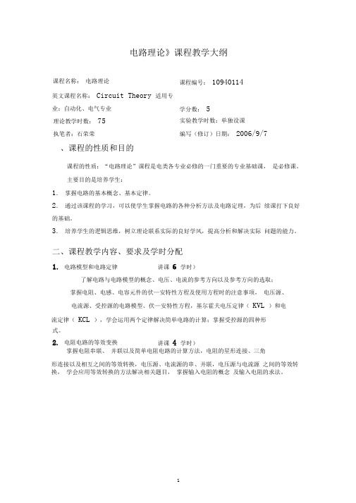
电路理论》课程教学大纲课程名称: 电路理论 课程编号: 10940114英文课程名称: Circuit Theory 适用专业:自动化、电气专业、课程的性质和目的课程的性质:“电路理论”课程是电类各专业必修的一门重要的专业基础课, 是必修课。
主要目的是培养学生:1. 掌握电路的基本概念、基本定律。
2. 通过该课程的学习,可以使学生掌握电路的各种分析方法及电路定理,为后 续课打下良好的基础。
3. 培养学生的逻辑思维,树立理论联系实际的良好学风,提高分析和解决实际 问题的能力。
二、课程教学内容、要求及学时分配了解电路与电路模型的概念、电压、电流的参考方向以及参考方向的选取;掌握电阻、电感、电容元件的伏—安特性方程及使用方程时的注意事项, 电压源、电流源、受控源的电路模型、伏—安特性方程,基尔霍夫电压定律( KVL )和电流定律( KCL ),学会运用两个定律解决简单电路的计算;掌握受控源的四种形掌握电阻串联、 并联以及简单电阻电路的计算方法,电阻的星形连接、三角形连接以及相互之间的等效转换,电压源、电流源的串、并联,电压源与电流源 之间的等效转换, 学会应用等效转换的方法解决相关题目, 掌握输入电阻的概念 及输入电阻的求法。
理论教学时数: 75实验教学时数:单独设课执笔者:石荣荣编写(修订)日期: 2006/9/7 学分数: 51. 电路模型和电路定律 讲课 6 学时)式。
2. 电阻电路的等效变换 讲课 4 学时)3. 电阻电路的一般分析方法 讲课 6 学时) 掌握KCL 、KVL 独立方程的个数及独立回路的选择方法; 了解支路电流法及 方程的列写过程;掌握网孔电流法,重点掌握回路电流法,结点电压法的思路。
学会运用三种方法求解一般电阻电路, 难点是当电路中存在无伴电压源、 流源时方程的列写方法。
了解替代定理的使用条件和使用方法; 重点掌握线性电路的叠加定理, 宁定理和诺顿定理的内容, 学会利用这些定理解决复杂电路的分析和计算; 最大功率传输定理及其使用过程;了解特勒根定理,互易定理的基本内容。
[VIP专享]80110104-《电路理论(1)》教学大纲
![[VIP专享]80110104-《电路理论(1)》教学大纲](https://img.taocdn.com/s3/m/ee4e764fc1c708a1284a44c5.png)
《电路理论(1)》课程教学大纲课程编号: 80110104课程名称:电路理论(1)英文名称: Circuit Theory(1)总学时: 40 讲课学时:40学 分: 2.5适用对象: 电气工程及其自动化专业等先修课程:高等数学B(1)、线性代数、大学物理(1)课程类型: 专业基础课一、课程性质、目的和任务本课程是电类等专业的一门重要的技术基础课,是研究电路理论的入门课程,是继续学习电路理论、后续专业基础课和专业课的桥梁。
本课程已成为培养工程技术人员,特别是电气工程师的重要基础。
它的任务是通过本课程的学习,使学生掌握电阻电路的基本概念、基本理论和分析计算电路的基本方法,为进一步学习电路理论打下坚实基础,并为后续课程准备必要的电路知识。
电路理论这门课程理论严密,逻辑性强,在培养学生的辩证抽象思维能力和严肃认真的科学作风,树立理论联系实际的科学观点和提高学生分析问题解决问题的能力、培养学生的创新意识以及加强基本技能训练等方面起着重要的作用。
二、教学内容、方法及基本要求(黑体,小4号字)1教学内容和方法第一部分电路模型及其基本规律本部分基本内容(1)基本概念:集中参数电路模型、电路的常用物理量(电流、电压、功率)、参考方向(2)基尔霍夫定律(电流定律、电压定律)、KCL方程和KVL方程的独立性(3)电路元件的特性方程及伏安关系线性电阻、独立电源、线性电容、线性电感、受控源(4)用两类约束直接分析电路本部分扩展内容实际电阻器、电容器和线圈的电路模型教学重点(1)参考方向和功率的计算(2)KCL方程和KVL方程的列写(3)元件的伏安关系(4)利用两类约束将一个电压或电流用其它电压、电流表示第二部分电路的等效变换分析法本部分基本内容(1)简单电路的分析单回路电路和双节点电路、分压公式和分流公式(2)等效化简分析法等效及等效变换的概念等效二端网络常用的基本等效二端网络电阻的串并联等效化简、独立源的串并联化简、电源模型之间的等效变换多余元件的处理、含受控源网络的等效化简星形网络和三角形网络的(Y-△)等效变换(3)输入电阻本部分扩展内容电源位移、利用等电位点分析电路教学重点(1)简单电路的分析(2)混联电路的等效化简分析(3)对称Y-△变换(4)输入电阻的求法(5)电桥平衡第三部分复杂电阻电路的分析本部分基本内容(1)支路分析法(2)节点分析法(3)网孔分析法(4)图论的基本知识(5)回路分析法本部分扩展内容改进节点法、用PSpice进行电路仿真计算教学重点(1)节点分析法(2)网孔分析法第四部分电路定理本部分基本内容(1)叠加定理和齐性定理(2)等效电源定理(戴维南定理和诺顿定理)(3)最大功率传递定理(4)替代定理(5)特勒根定理(6)互易定理(7)对偶原理本部分扩展内容定理的综合应用教学重点(1)叠加定理(2)等效电源定理和最大功率传递定理第五部分双口网络本部分基本内容(1)双口网络的基本概念(2)双口网络的参数及其方程开路电阻参数、短路电导参数、传输参数、混合参数、各参数之间的关系(3)双口网络的等效电路(4)双口网络的复合联接(级联、串联、并联)(5)用端口法分析电路(6)理想运算放大器及含理想运算放大器电阻电路的分析(7)回转器本部分扩展内容含源双口网络、多口网络、跨导运算放大器、电流传输器教学重点(1)双口网络的参数(2)含理想运放电阻电路的分析第六部分简单非线性电阻电路本部分基本内容(1)非线性二端电阻元件(2)非线性电阻电路的方程(3)非线性电阻电路的图解法曲线相加法(DP图)和曲线相交法(直流工作点)(4)非线性电阻电路的小信号分析法(5)分段线性化法本部分扩展内容运算放大器的非线性低频模型、用PSpice进行非线性电阻电路仿真计算教学重点(1)含单一非线性电阻电路的分析(2)小信号分析法2 基本要求该课程介绍电路的基本概念、元件的特性方程和基尔霍夫定律以及电阻电路的分析方法,是电路分析的基础部分。
电路原理 (1.6.1)--节点法,回路法
支路。
iS3
un1 1
R3
un2 2
iS1
R1
iS2
R2
R4
R5
0
?× ( 1 R1
+
1 R2
+
1 R3
+
1 R4
)un1
-
(
1 R3
+
1 R4
)un2
=
- iS1
-
iS2
+
iS3
节点 1 与节点 2 之 间 的
互电导,等于接在 节
G21un1+G22un2 = isn2 un1 1
iS3 i3
R3 u2n2
iS1
i1
R1
iS2
R2
i4 i2
R4
i5 R5
0
Principles of Electric Circuits Lecture 6 Tsinghua University 2013
16
一般情 (n况个 独 立 节 点)
G11un1+G12un2+…+G1nunn=iSn1 G21un1+G22un2+…+G2nunn=iSn2
Gn1un1+Gn2un2+…+Gnnunn=iSnn
其中 Gii 自电导,等于接在节点 i 上所有支路的电导之 和。
Gij = G自ji 电互导电总导为,正等。于接在节点 i 与节点 j 之间的 所有
15
(
1 R1
+
1 R2
+
1 R3
+
1 R4
)
un1
-
电路理论基础
法,如半导体器件的模型是在半导体物理提供 的概念与方法基础上,通过对其中载流子运动 过程的分析后得出的。
Real R, L, C Components: General Case
High Frequency At Low Frequency
⎧
⎪
0,
⎪
I DS
=
⎪ ⎨
⎪
W Kp L
(VGS
− VT
−
VDS 2
)VDS
,
⎪ ⎪⎩K p
W L
(VGS
−VT )2 2
(1+ λVDS ),
VGS < VT VGS > VT ,VGD < VT VGS > VT ,VGD > VT
动态模型同样是再在上式基础上加上各种寄生电 容。
MOSFET 中的寄生电容
∫ f (t) = 1 +∞ F ( jω)e jωtdω
2π −∞
∫ f (t) = 1 σ + j∞ F (s)estds
2π j σ − j∞
电路理论的发展(1)
电路理论始于19世纪早中期的欧姆定律与基尔霍 夫定律,由于早期电报与电话通信、电机工程的 发展而形成一些基本概念与方法。
20世纪初电子三极管的发明使长距离通信、无线 电广播与电视得到发展,滤波、放大、振荡等基 本电路得到逐渐深入的研究。
MOSFET 完整模型
MOSFET完整模型
电路理论(3)
线性电阻电路 与多端口分析
HDU, 9/2011
1、节点电压方程
对一个电路作分析计算,基本的方法是根据元器 件的特性与电路的基本规律KCL & KVL列写出电 路方程,再作进一步计算。
【都灵理工】电路理论CircuitTheory_cap7
RC circuit
ODE solution
RL circuit natural evolution of circuit
RC circuit
solution equations for t > 0
Circuit Theory Chap. 7 M. Repetto dynamics
ODE
for t > 0 the switch is open so that current A must ow through R and C components solution equations are written in the same way as for resistive circuits
RC circuit
ODE solution
RL circuit natural evolution of circuit
t<0
t>0
A
v=0
R
C
A
R
iR
iC
C
v
RC circuit
Circuit Theory Chap. 7 M. Repetto dynamics
ODE
solution equations for t < 0
RC circuit
Circuit Theory Chap. 7 M. Repetto dynamics
ODE
solution equations for t > 0
by considering that R and C are parallel connected v iR = R and thus by substituting inside the KCL A = iR + iC C v dv + =A dt R (10)
【都灵理工】工程材料学基础_08_electrical properties
Engineering Materials 2009/2010 Marco ACTIS GRANDE
Engineering Materials 2009/2010 Marco ACTIS GRANDE
Electrical conductivity is the reciprocal of the resistivity, or
Engineering Materials 2009/2010 Marco ACTIS GRANDE
The electrical properties of a solid material are a consequence of its electron band structure. Four different types of band structures are possible at 0 K:
In all conductors, semiconductors, and many insulating materials, only electronic conduction exists, and the magnitude of the electrical conductivity is strongly dependent on the number of electrons available to participate in the conduction process. The number of electrons available for electrical conduction in a particular material is related to the arrangement of electron states or levels with respect to energy, and then the manner in which these states are occupied by electrons.
电气英文术语
电路的基本概念及定律电源source电压源voltage source电流源current source理想电压源ideal voltage source理想电流源ideal current source伏安特性volt-ampere characteristic电动势electromotive force电压voltage电流current电位potential电位差potential difference欧姆Ohm伏特Volt安培Ampere瓦特Watt焦耳Joule电路circuit电路元件circuit element电阻resistance电阻器resistor电感inductance电感器inductor电容capacitance电容器capacitor电路模型circuit model参考方向reference direction参考电位reference potential欧姆定律Ohm’s law基尔霍夫定律Kirchh off’s law基尔霍夫电压定律Kirchhoff’s voltage law(KVL)基尔霍夫电流定律Kirchhoff’s current law(KCL)结点node支路branch回路loop网孔mesh支路电流法branch current analysis网孔电流法mesh current analysis结点电位法node voltage analysis电源变换source transformations叠加原理superposition theorem网络network无源二端网络passive two-terminal network有源二端网络active two-terminal network戴维宁定理Thevenin’s theorem诺顿定理Norton’s theorem开路(断路)open circuit短路short circuit开路电压open-circuit voltage短路电流short-circuit current交流电路直流电路direct current circuit (dc)交流电路alternating current circuit (ac)正弦交流电路sinusoidal a-c circuit平均值average value有效值effective value均方根值root-mean-squire value (rms)瞬时值instantaneous value电抗reactance感抗inductive reactance容抗capacitive reactance法拉Farad亨利Henry阻抗impedance复数阻抗complex impedance相位phase初相位initial phase相位差phase difference相位领先phase lead相位落后phase lag倒相,反相phase inversion频率frequency角频率angular frequency赫兹Hertz相量phasor相量图phasor diagram有功功率active power无功功率reactive power视在功率apparent power功率因数power factor功率因数补偿power-factor compensation串联谐振series resonance并联谐振parallel resonance谐振频率resonance frequency频率特性frequency characteristic幅频特性amplitude-frequency response characteristic 相频特性phase-frequency response characteristic截止频率cutoff frequency品质因数quality factor通频带pass-band带宽bandwidth (BW)滤波器filter一阶滤波器first-order filter二阶滤波器second-order filter低通滤波器low-pass filter高通滤波器high-pass filter带通滤波器band-pass filter带阻滤波器band-stop filter转移函数transfer function波特图Bode diagram傅立叶级数Fourier series三相电路三相电路three-phase circuit三相电源three-phase source对称三相电源symmetrical three-phase source对称三相负载symmetrical three-phase load相电压phase voltage相电流phase current线电压line voltage线电流line current三相三线制three-phase three-wire system三相四线制three-phase four-wire system三相功率three-phase power星形连接star connection(Y-connection)三角形连接triangular connection(D- connection ,delta connection) 中线neutral line电路的暂态过程分析暂态transient state稳态steady state暂态过程,暂态响应transient response换路定理low of switch一阶电路first-order circuit三要素法three-factor method时间常数time constant积分电路integrating circuit微分电路differentiating circuit磁路与变压器磁场magnetic field磁通flux磁路magnetic circuit磁感应强度flux density磁通势magnetomotive force磁阻reluctance电动机直流电动机dc motor交流电动机ac motor异步电动机asynchronous motor同步电动机synchronous motor三相异步电动机three-phase asynchronous motor 单相异步电动机single-phase asynchronous motor 旋转磁场rotating magnetic field定子stator转子rotor转差率slip起动电流starting current起动转矩starting torque额定电压rated voltage额定电流rated current额定功率rated power机械特性mechanical characteristic继电器-接触器控制按钮button熔断器fuse开关switch行程开关travel switch继电器relay接触器contactor常开(动合)触点normally open contact常闭(动断)触点normally closed contact时间继电器time relay热继电器thermal overload relay中间继电器intermediate relay可编程控制器(PLC)可编程控制器programmable logic controller语句表statement list梯形图ladder diagram半导体器件本征半导体intrinsic semiconductor掺杂半导体doped semiconductorP型半导体P-type semiconductorN型半导体N--type semiconductor自由电子free electron空穴hole载流子carriersPN结PN junction扩散diffusion漂移drift二极管diode硅二极管silicon diode锗二极管germanium diode阳极anode阴极cathode发光二极管light-emitting diode (LED)光电二极管photodiode稳压二极管Zener diode晶体管(三极管)transistorPNP型晶体管PNP transistorNPN型晶体管NPN transistor发射极emitter集电极collector基极base电流放大系数current amplification coefficient场效应管field-effect transistor (FET)P沟道p-channelN沟道n-channel结型场效应管junction FET(JFET)金属氧化物半导体metal-oxide semiconductor (MOS)耗尽型MOS场效应管depletion mode MOSFET(D-MOSFET)增强型MOS场效应管enhancement mode MOSFET(E-MOSFET)源极source栅极grid漏极drain跨导transconductance夹断电压pinch-off voltage热敏电阻thermistor开路open短路shorted基本放大器放大器amplifier正向偏置forward bias反向偏置backward bias静态工作点quiescent point (Q-point)等效电路equivalent circuit电压放大倍数voltage gain总的电压放大倍数overall voltage gain饱和saturation截止cut-off放大区amplifier region饱和区saturation region截止区cut-off region失真distortion饱和失真saturation distortion截止失真cut-off distortion零点漂移zero drift正反馈positive feedback负反馈negative feedback串联负反馈series negative feedback并联负反馈parallel negative feedback共射极放大器common-emitter amplifier射极跟随器emitter-follower共源极放大器common-source amplifier共漏极放大器common-drain amplifier多级放大器multistage amplifier阻容耦合放大器resistance-capacitance coupled amplifier 直接耦合放大器direct- coupled amplifier输入电阻input resistance输出电阻output resistance负载电阻load resistance动态电阻dynamic resistance负载电流load current旁路电容bypass capacitor耦合电容coupled capacitor直流通路direct current path交流通路alternating current path直流分量direct current component交流分量alternating current component变阻器(电位器)rheostat电阻(器)resistor电阻(值)resistance电容(器)capacitor电容(量)capacitance电感(器,线圈)inductor电感(量),感应系数inductance正弦电压sinusoidal voltage集成运算放大器及应用差动放大器differential amplifier运算放大器operational amplifier(op-amp)失调电压offset voltage失调电流offset current共模信号common-mode signal差模信号different-mode signal共模抑制比common-mode rejection ratio (CMRR) 积分电路integrator(circuit)微分电路differentiator(circuit)有源滤波器active filter低通滤波器low-pass filter高通滤波器high-pass filter带通滤波器band-pass filter带阻滤波器band-stop filter波特沃斯滤波器Butterworth filter切比雪夫滤波器Chebyshev filter贝塞尔滤波器Bessel filter截止频率cut-off frequency上限截止频率upper cut-off frequency下限截止频率lower cut-off frequency中心频率center frequency带宽Bandwidth开环增益open-loop gain闭环增益closed-loop gain共模增益common-mode gain输入阻抗input impedance电压跟随器voltage-follower电压源voltage source电流源current source单位增益带宽unity-gain bandwidth频率响应frequency response频响特性(曲线)response characteristic波特图the Bode plot稳定性stability补偿compensation比较器comparator迟滞比较器hysteresis comparator阶跃输入电压step input voltage仪表放大器instrumentation amplifier隔离放大器isolation amplifier对数放大器log amplifier反对数放大器antilog amplifier反馈通道feedback path反向漏电流reverse leakage current相位phase相移phase shift锁相环phase-locked loop(PLL)锁相环相位监测器PLL phase detector和频sum frequency差频difference frequency波形发生电路振荡器oscillatorRC振荡器RC oscillatorLC振荡器LC oscillator正弦波振荡器sinusoidal oscillator三角波发生器triangular wave generator方波发生器square wave generator幅度magnitude电平level饱和输出电平(电压)saturated output level功率放大器功率放大器power amplifier交越失真cross-over distortion甲类功率放大器class A power amplifier乙类推挽功率放大器class B push-pull power amplifier OTL功率放大器output transformerless power amplifier OCL功率放大器output capacitorless power amplifier 直流稳压电源半波整流full-wave rectifier全波整流half-wave rectifier电感滤波器inductor filter电容滤波器capacitor filter串联型稳压电源series (voltage) regulator开关型稳压电源switching (voltage) regulator集成稳压器IC (voltage) regulator晶闸管及可控整流电路晶闸管thyristor单结晶体管unijunction transistor(UJT)可控整流controlled rectifier可控硅silicon-controlled rectifier峰点peak point谷点valley point控制角controlling angle导通角turn-on angle门电路与逻辑代数二进制binary二进制数binary number十进制decimal十六进制hexadecimal二-十进制binary coded decimal (BCD)门电路gate三态门tri-state gate与门AND gate或门OR gate非门NOT gate与非门NAND gate或非门NOR gate异或门exclusive-OR gate反相器inverter布尔代数Boolean algebra真值表truth table卡诺图the Karnaugh map逻辑函数logic function逻辑表达式logic expression组合逻辑电路组合逻辑电路combination logic circuit译码器decoder编码器coder比较器comparator半加器half-adder全加器full-adder七段显示器seven-segment display时序逻辑电路时序逻辑电路sequential logic circuitR-S 触发器R-S flip-flopD触发器D flip-flopJ-K触发器J-K flip-flop主从型触发器master-slave flip-flop置位set复位reset直接置位端direct-set terminal直接复位端direct-reset terminal寄存器register移位寄存器shift register双向移位寄存器bidirectional shift register 计数器counter同步计数器synchronous counter异步计数器asynchronous counter加法计数器adding counter减法计数器subtracting counter定时器timer清除(清0)clear载入load时钟脉冲clock pulse触发脉冲trigger pulse上升沿positive edge下降沿negative edge时序图timing diagram波形图waveform脉冲波形的产生与整形单稳态触发器monostable flip-flop双稳态触发器bistable flip-flop无稳态振荡器astable oscillator晶体crystal555定时器555 timer模拟信号与数字信号的相互转换模拟信号analog signal数字信号digital signalAD转换器analog -digital converter (ADC)DA转换器digital-analog converter (DAC)半导体存储器只读存储器read-only memory(ROM)随机存取存储器random-access memory(RAM)可编程ROM programmable ROM(PROM)11 / 11。
EE233电路理论实验1:RC电路说明书

EE 233 Circuit TheoryLab 1: RC CircuitsTable of Contents1Introduction (1)2Precautions (1)3Prelab Exercises (2)3.1The RC Response to a DC Input (2)3.1.1Charging RC Circuit (2)3.1.2Discharging RC Circuit (3)3.1.3Square Wave Input (3)3.1.4Multiple-stage RC Circuits (3)3.2The RC Response to a Sinusoidal Input (4)3.2.1Time-domain RC Response (4)3.2.2Frequency-domain RC Response (5)4Experimental Procedure and Data Analysis (6)4.1The RC Response to a DC Input (6)4.1.1Square Wave Input Analysis (6)4.1.2Time Constant Measurement (7)4.2The RC Response to a Sinusoidal Input (7)5Reference Material (9)5.1RC Step Response and Timing Parameters (9)5.2Elmore Delay Estimation (10)5.3Frequency Response of a Circuit System (10)5.4Parameter Extraction via Linear Least-Squares-Fit Technique (11)Table of FiguresFigure 3.1.1: Single-stage RC circuit. (2)Figure 3.1.2: Two-stage RC circuit. (4)Figure 3.1.3: Three-stage RC circuit. (4)Figure 3.2.1: An RC circuit with the output over the resistor. (5)Figure 4.1.1: RC circuit for lab experiment. (6)Figure 5.1.1: Timing parameters of signal waveforms. (9)Figure 5.2.1: N-stage RC circuit delay estimation. (10)1 IntroductionThis lab is designed to teach students methods for characterizing circuit systems, and more specifically, an RC circuit system. This lab will also familiarize students with the test bench instruments used in this class by having them use the equipment to analyze some fundamental response trends of step and sinusoidal input functions for an RC circuit.A circuit system can be pictured as a box with inputs and outputs, and the characteristics of this system can be represented by its input and output signals, e.g. voltage and current. A signal contains three parameters: magnitude, frequency, and phase. Any change of these parameters in the input signal will affect the output signal.The RC circuit has many interesting characteristics while staying one of the most basic circuit systems. This lab is going to allow students to observe these characteristics and teach them how to analyze the output signals with changes in input magnitude or frequency.This lab is split into a prelab exercise and hardware implementation. Submit one prelab report and one lab report per group, with the members’ names are clearly written on the front page. There is no template for the prelab report, and the lab report template is available on Canvas. These reports must be in pdf format. There are multiple apps, including CamScanner, for Apple and Android phones that turn photos into pdf’s. 2PrecautionsNone of the devices used in this set of experiments are particularly static sensitive; nevertheless, you should pay close attention to the circuit connections and the polarity of the power supplies, function generator, and oscilloscope inputs.3 Prelab Exercises3.1 The RC Response to a DC Input3.1.1 Charging RC CircuitThe differential equation for v out (t) is the most fundamental equation describing the RC circuit, and it can be solved if the input signal v in (t) and an initial condition are given.Figure 3.1.1: Single-stage RC circuit. Now suppose the input signal v in (t) has been zero for a long time, and then is changed to V o , a positive constant, at time t =0. The input signal is then a step function, which means:v in (t )=V o u(t)={0, t <0V o , t ≥0The initial condition for v out (t ) is needed to solve the differential equation. The output voltage should be zero when t <0, since there is no input until t =0. Thus, the initial condition for v out (t ) is v out (0)=0.Download Lab1_Prelab.m and lab1plot.m from the Canvas webpage, making sure they are in the same folder on your computer. Suppose V o =5V, R =10k Ω, and C =0.01µF.To do this, open Lab1_Prelab.m using Matlab (there is no need to open the other file) and read the developer comments about how to use the lab1plot function. Run the script, select “Change Folder” if the warning appears, and the plot for Prelab #3 should appear. You are not expected to know how to use Matlab in this course, so feel free to ask the TA for assistance if you have difficulty using the script.3.1.2 Discharging RC CircuitYou have now analyzed t he RC circuit’s step response, and you also have a general idea of what this response looks like by plotting it with the input voltage. Now suppose the input signal has been V o , a positive constant, for a long time before being changed to zero at t =0, which meansv in (t )=V o u(−t)={V o , t <00, t ≥03.1.3 Square Wave InputIf the input signal is turned on and off periodically then it becomes a square wave. Suppose the period of this square wave is T , and its duty cycle (the ratio of how long the square wave is on vs. how long it’s off) is 50%. If half of the period, T/2≫RC then the output voltage goes to its limit before the input changes. Example: If T =10RC , the ratio V out (T/2)−V out (0)V 0=V 0exp (−5)V=0.67%<1%. So the change of output voltage is almost equal to the change of the input voltage, andit means the output voltage is close to its limit.Refer to Reference 5.1 to answer Prelab #6.When deriving the expressions, notice that these timing parameters are independent of the input voltage. 3.1.4 Multiple-stage RC CircuitsRefer to Reference 5.2 Elmore Delay Estimation to answer Prelab #8.Figure 3.1.2: Two-stage RC circuit.Figure 3.1.3: Three-stage RC circuit.3.2The RC Response to a Sinusoidal Input3.2.1Time-domain RC ResponseWhile the input square wave changes the magnitude of the signal, exploration of the RC response to an AC signal can show more interesting characteristics of the RC circuit. Looking back on Figure 3.1.1, the single-stage RC circuit, suppose we are using a sinusoidal wave as an input signal, v in(t)=V o cos(ωt), where ω is the angular frequency of the signal.This differential equation is the fundamental equation describing the RC circuit system. The solution for the steady-state output voltage isv out(t)=V o1+R2C2ω2[cos(ωt)+RCωsin(ωt)]This solution shows that v out(t) is a function of the signal’s frequency f and time t. The relationship between angular frequency ω and signal frequency f is ω=2πf.Suppose V o =1V (notice it’s different), f =1kHz, R =10k Ω, and C =0.01µF.3.2.2 Frequency-domain RC ResponseNow consider the solution for v out (t ) with the signal’s frequency f being the independent variable. The output voltage is a sinusoidal wave with the same frequency as the input voltage, and its magnitude is given by|V out (f )|=V o √1+4π2R 2C 2f 2Suppose V o =1V, R =10k Ω, and C =0.01µF. Notice that the frequency-domain plot’s x -axis is logarithmic, that is, each division is 10 times greater than the previous. This frequency-domain plot will become very important in subsequent labs, where you will use it to design filters for your audio mixer.Now consider another RC system in Figure 3.2.1,in which the output voltage is over the resistor,rather than the capacitor.The output voltage is now the input signal minusthe voltage over the capacitor, and its magnitude isgiven bySuppose V o =1V, R =10k Ω, and C =0.01µF.Figure 3.2.1: An RC circuit with the output over the resistor. |V out (f )|=o +4π2R 2C 2f 24 Experimental Procedure and Data Analysis4.1 The RC Response to a DC Input4.1.1 Square Wave Input AnalysisBuild the circuit in Figure 4.1.1 and set thefunction generator to provide a square wave inputas follows:a) The period T ≥4ms (to ensure that T ≫RC ).This value of T guarantees that the output signalhas sufficient time to reach a final value beforethe next input transition. Record your value ofT . b) The minimum voltage is 0V and maximumvoltage is 5V. Note that you may need to manually set the offset to achieve this waveform. Use the oscilloscope to display this waveform on Channel 1 to verify that the amplitude is correct. We use these amplitudes since it they are common in computer systems (false = 0V, true = 5V).Use Channel 2 of the oscilloscope to display the output voltage over the capacitor. Adjust the time base to display 3 complete cycles of the signals. Capture the output from the scope display with both the waveforms and the measured values. Turn this oscilloscope waveform in as part of your lab report.Using the oscilloscope ’s Cursor menu, record the period T of the input signal, as well as the maximum and minimum values of the output signal. Then measure the time value of the 10% point of V out , the time value of the 90% point of V out , and the time value of the 50% point of V out .Note: Instructions for using the lab equipment are found in Lab Equipment.pdf , on the Canvas webpage. Percent error is defined as:PE =|actual value −theoretical value|theoretical value ×100%Now clear all the oscilloscope measurements. Use the measurement capability of the oscilloscope to measure the rise time of v out (t), the fall time of v out (t), and the two delay times t PHL and t PLH .Figure 4.1.1: RC circuit for lab experiment.4.1.2Time Constant MeasurementThe time constant τ=RC is one of the most important characteristics of RC circuit, and its value can be extracted from measured data.To measure the time constant τ, use the oscilloscope’s Cursor menu to measure the voltage and time values at 10 points on the v out waveform during one interval when v out either rises or falls with time (pick one interval only). Note that the time values should be referred to time t=0 at the point where the input signal rises from 0V to 5V or falls from 5V to 0V. Record the 10 measurements.Explanation: Consider the ratio of |v out−v in| and high voltage V0. It isRatio(t)=|v out(t)−v in||V0|=e−tτand it can be calculated by measured data. So the function ln (Ratio(t)) is linearaccording to time, and the slope is −1τ. Read Reference 5.4 for more information.Now build two-stage and three-stage RC circuits and measure time constant τtwo−stage and τthree−stage using the same methods as the single stage circuit analysis. Record all your measurements.4.2The RC Response to a Sinusoidal InputRebuild the circuit in Figure 4.1.1 and set the function generator to provide a sinusoidal input with:a) An amplitude of 1V, which means V pk−pk=2Vb) A frequency of 1kHz.Connect Channel 1 to the input voltage and Channel 2 to the voltage over the capacitor as the output. Display the input and output voltages simultaneously on the oscilloscope in 3 complete cycles. Capture the output from the scope display with both the waveforms and the measured values. Turn this oscilloscope waveform in as part of your lab report.Now measure the RC response to sinusoidal signals with various frequencies. Keep the input amplitude at 1V, but sweep the frequency from the starting input frequency of 10Hz, varying it using a 1-2-5 sequenceup to 1MHz (i.e. set input frequency to 10Hz, 20Hz, 50Hz, 100Hz, 200Hz … up to 1MHz). Record the amplitudes of the output signals.Once done, switch the locations of the resistor and capacitor and change the output to be the voltage over the resistor. Set the function generator to provide a sinusoidal wave input with 1V amplitude. As before, sweep the frequency starting from 10Hz using the 1-2-5 sequence up to 1MHz. Record the amplitudes of the output signals.5Reference Material5.1RC Step Response and Timing ParametersThe step response of a simple RC circuit, illustrated in Figure 5.1.1, is an exponential signal with time constant τ=RC. Besides this timing parameter, four other timing parameters are important in describing how fast or how slow an RC circuit responds to a step input. These timing parameters are marked in Figure5.1.1, as three voltage levels:a) The 10%-point is the point at which the output voltage is 10% of the maximum output voltage.b) The 50%-point is the point at which the output voltage is 50% of the maximum output voltage.c) The 90%-point is the point at which the output voltage is 90% of the maximum output voltage.Figure 5.1.1: Timing parameters of signal waveforms.The three timing parameters are defined as follows:a) Rise time: the time interval between the 10%-point and the 90%-point of the waveform when the signal makes the transition from low voltage (L) to high voltage (H). Notation: t r.b) Fall time: the time interval between the 90%-point and the 10%-point of the waveform when the signal makes the transition from high voltage (H) to low voltage (L). Notation: t f.c) Delay time (or propagation delay time): the time interval between the 50%-point of the input signal and the 50%-point of the output signal when both signals make a transition. There are two delay times depending on whether the output signal is going from L to H (delay notation t PLH) or from H to L (delay notation t PHL). The subscript P stands for “propagation.”Note that the rise time and the fall time are defined using a single waveform (the output waveform), while the delay time is defined between two waveforms: the input waveform and the corresponding output waveform.5.2Elmore Delay EstimationFigure 5.2.1 depicts a multi-element configuration. The resistor R1 in this figure charges all N capacitors downstream of its own position. The Elmore estimated delay τ1 from point x0 to x1 is thereforeτ1=R1∑C mNm=1Resistor R2 charges only capacitors numbered 2 through N, so the estimated delay from point x1 to x2 isτ2=R2∑C mNm=2Working down the row, the total delay for the whole circuit is then estimated as:τ=∑R nNn=1∑C m Nm=nFigure 5.2.1: N-stage RC circuit delay estimation.5.3Frequency Response of a Circuit SystemAn analog circuit system has different responses for sine waves with different frequencies. The magnitude of the output voltage always changes in terms of frequencies if the magnitude of the input sine wave stays the same. Therefore, the frequency response is the quantitative measure to characterize the system. Since any input signal can be regarded as the sum of a set of sinusoidal waves, the output signal will have different responses to input waves with the set of frequencies. If the circuit has high magnitude for low frequencies, and close to zero magnitude for high frequencies, the high frequencies will be removed by the circuit in the output signal, and vice versa.The frequency response is one of the main characteristics of the system, and you will explore methods of analyzing the frequency response in the following labs.5.4Parameter Extraction via Linear Least-Squares-Fit TechniqueThe important parameters of V out(t) are the maximum amplitude and the time constant τ. The maximum amplitude is easily measured by using the oscilloscope. Measuring the time constant directly and accurately is more difficult, since the waveform is an exponential function of time. A linear least-squares-fit procedure can be used in the lab to extract the time constant from measured voltage and time values as follows.The equation for V out(t) during the time interval when V out(t) falls with time, which you can write based on what you learned in prerequisite courses, can be manipulated to provide a linear function in terms of the time t. The slope of this line is then used to extract the time constant τ.Alternatively, the equation for V out(t) during the time interval when V out(t) rises with time can also be manipulated to provide a linear function in terms of the time t. The slope of this line is then used to extract the time constant τ.In the lab, you will measure a set of data points (t,V out). These values, after the appropriate manipulation as above, can be used to plot a straight line, whose slope is a function of τ. You can use any procedure or a calculator to plot and extract the slop. The slope value will then be used to calculate the time constant τ. Make sure you understand this procedure and be ready to use it in the lab. Note that the more points you measure, the more accurate the extracted value for τ.。
电路理论发展史

电路理论发展史电路理论的历史与发展概况电路理论作为一门独立的学科出现于人类历史中大约已有200多年了,在这纷纭变化的200多年里,电路理论从那种用莱顿瓶和变阻器描述问题的原始概念和分析方法逐渐演变成为一门抽象化的基础理论科学,其间的发展和变化贯穿于整个电气科学的发展之中。
如今它不仅成为了整个电气科学技术中不可缺少的理论基础,同时也在开拓和发展新的电气理论和技术方面起着重要的作用。
电路理论是一个极其美妙的领域,在这一领域内,数学、物理学、信息工程、电气工程与自动控制工程等学科找到了一个和谐的结合点,其深厚的理论基础和广泛的实际应用使其具有旺盛持久的生命力。
因而,对于许多有关的学科来说,电路理论是一门非常重要的基础理论课。
1. 历史的回顾电,这个词来源于古希腊语“琥珀(elektron)”,琥珀是一种树脂化石。
大约在公元前600年,古希腊人第一次产生了电场,其方法是用一块丝绸或毛皮与琥珀棒摩擦。
人们注意到有一些带电的材料被带电的玻璃片所吸引,而另一些却被排斥,这说明存在两种不同的电。
本杰明.富兰克林称这两种电(或电荷)为正电和负电(正电荷或负电荷)。
法国科学家查利·奥古斯丁·库仑(Charlse-Augustin de Coulomb )和英国科学家卡文迪什(Cavendish)在十八世纪研究了这种靠摩擦产生的静电,发现了这种电所遵循的规律,这个规律被称为库仑定律(178年)。
然而电科学真正的突破是从1800年伏打(Alessandro Voltar)发明化学电池后开始的。
后人采用伏特作为电压的单位,以纪念科学家伏打。
由于伏打电池使电流连续成为可能,因而使很多电的实验变得简单可行,于是在短期内就有了一系列重要的发现。
比如,1820年奥斯特(H.C.Oersted)发现,罗盘指针在载流导体旁会发生偏转,于是他断定:电荷的流动产生了磁。
这一发现揭开了电学理论的新的一页。
1825年安培(A.M.Ampere)提出了描述电流与磁之间关系的安培定律,同时毕奥和沙伐尔也用实验表明了电流与磁场强度的关系。
电子电路基础

2022 电路原理一、 绪论1.1 EECS:1.2 电路的组成:源(发电厂,光电池,麦克风等),负荷(电动机,扬声器,屏幕等),能量和信号处理电路(变压器,放大器等),导线与开关(输电线路,电路板等). 1.3 电路的变量:1.3.1 电流current:电荷的时间变化率(单位时间内从A 到B 的正电荷量)I =dQ dt1.3.2 电压voltage:电场力移动单位电荷做的功(电场力将正电荷从A 移动到B 所作的功)(电位的降低)Uab =dW abdq=−Uba =φa −φb1.3.3电位potential:从某点到参考节点的电压参考点(reference point)的电位是零.两点间的电压等于两点之间的电位差.两点间的电压与参考节点的选取无关.1.3.4 电动势eletromotive force:非电场力将单位正电荷从B 移动到A 所作的功(电位的升高)e BA =dW BAdq=φA −φB1.4 变量的大小写:不变的量大写,可能变化的量小写. 1.5 电压和电流的参考方向:电压或电流的方向未知;电压或电流的方向随时间变化.表示电流参考方向的两种方法:箭头;双下标(i AB )-参考方向从A 指向B二端元件上电压参考方向和电流参考方向之间的关系关联参考方向associated reference directions:u =Ri 均正端流入,负端流出非关联参考方向non-associated reference directions:u =−Ri1.6 电路的功率Power:单位时间内从A 到B 所做的功(元件吸收)P =dw dt =dw dq dq dt=ui1.6.1功率的计算:或全部按关联方向进行计算电阻总是吸收功率,电源可能吸收也可能发出功率.电路中被吸收功率之和一定等于发出功率之和.1.7总结:电压,电流都是参考方向;电动势是电源的本质参数;电压-电流有关联/非关联两种情况—功率有两种计算方法二、 电阻电路的基本分析方法:2.1 电阻器(Resistor): 2.1.1 电阻符号:2.1.2 G 电导(Conductance):G =1RUnit:S(西)(Siemens 西门子) 2.1.3 欧姆定律:电压电流采用关联参考方向:u =RiR- resistence Unit-Ω(欧姆)电压电流采用非关联参考方向:u =−Ri or i =−Gu2.1.4 开路与短路:当R=0(G=∞),视其为短路.u=0,i 由外电路决定; 当R=∞(G=0),视其为开路,i=0,u 由外电路决定电阻消耗的功率:p 吸=ui =i 2R =u2RP 发=ui =(−Ri )i =u(−u R )=−i 2R =−u2R阻值和功率是电阻器最重要的两大指标.R =ρL S2.2 独立电源(independent source):2.2.1 理想独立电压源(ideal independent voltage source):电路符号:特性:独立电压源两端的电压与电路其余部分无关.独立电压源的电流由外电路决定直流:u s为常数(Us)正弦交流:u s随时间变化,可以表示为u s=U m sinϖtu-i特性:零值电压源等效于零值电阻,等效于短路线.2.2.2理想独立电流源(independent current source):电路符号:特性:流经独立电流源的电流与电路的其余部分无关电流源上的电压由外电路决定直流:i s为常数(Is)正弦交流:i s随时间变化,可以表示为i s=I s sinωtu-i特性:零值电流源等效于零值电导(无穷大电阻),等效于开路线.2.2.3独立电源的短路和开路:理想电流源不能被开路(Is=C(C≠0));理想电压源不能被短路(Us=C=C(C≠0)).2.2.4独立电源的功率:先算支路量(电压U,电流I),再算功率(P).2.2.5实际电源:2.3受控元件:2.3.1受控电阻:开关:端口(port):端口由两个接线端构成,且满足如下条件:从一个接线端流入的电流等于从另一个接线端流出的电流二端元件自然构成一端口理想开关的u-i特性:一个压控电阻的实例:MOSFETU DS较小时,MOSFET等效为电阻;U DS较大时,MOSFET等效为电流源.2.3.2受控电源(Dependent source):定义:受控电压源:该电压源的电压由电路中某电压或电流控制.受控电流源:该电流源的电流由电路中某电压或电流控制.线性受控源的分类:压控电流源(Voltage Controlled Current Source(VCCS)):流控电流源(Current Controlled Current Source(CCCS)):流控电压源(Current Controlled Voltage Source(CCVS)):压控电压源(Voltage Controlled Voltage Source(VCVS)):进一步讨论:受控源不是二端元件;独立源电压/电流由电源本身决定,而受控源电压/电流直接由控制量决定独立源是真正电路中的”源”,受控源在电路中是能量或信号处理元件. 2.4基尔霍夫定律(Kirchhoff’s Laws):2.4.1术语:支路(branch):若干元件无分叉地首尾相连构成一个支路(b)节点(node):3个或更多支路的连接点(n)路径(path):两个节点间包含的支路回路(loop):由支路组成的闭合路径(l)网格(mesh):平面电路中不与其余支路相交的回路也有教材认为:二端元件构成一个支路;两个元件之间的接线端构成一个节点2.4.2Kirchhoff’s Current Laws(KCL):∑i(t)=0流出节点的电流的代数和为零/流入节点的电流的代数和为零∑i in(t)=∑i out(t)注意事项:只适用于集总参数电路;对有参考方向的电流仍然有效广义KCL:2.4.3Kirchhoff’s Voltage Laws(KVL):∑u(t)=0回路中所有电压(降)的代数和为零两种方向:顺时针/逆时针∑u drop(t)=∑u rise(t)广义KVL:电路中任意两点间的电压等于两点间任意一条路径经过的各元件电压的代数和U AB(沿l1)=U AB(沿l2)电压的唯一性:U AB=U2+U3U AB=U s1+U1−U S2−U4对于外部电路而言,电流源串联元件与否无影响2.52b法求解电路:b各独立元件约束,n-1个独立KCL,b-n+1个独立KVL;三、电路的等效变换:3.1电阻等效变换:3.1.1串并联可能改变的量应当以斜体表示.二端网络:与外部只有两个接线端相连的网络.无独立源二端网络:网络内部没有独立源的二端网络一个无独立源二端电阻网络可以用端口的入端电阻来等效:两个电路等效:两个电路u-i关系的形式和参数均一样电阻元件串联(无分叉的首尾相接):等效电阻Req:等效的相对性:除了选定电路之外的电路来说,这两个电路是等效的(相同的u-i形式和参数),对于被等效的两个电路内部来说,并没有什么关系.串联电阻元件的分压:电阻越大,压降越大.Us:电压形式表示的信号源负载电阻R L相对越大,负载上得到的信号越大电压源内阻R S相对越小,为负载提供信号的能力越强(带载能力强) 并联电阻元件(元件共用两个接线端):并联电阻器的分流:电导越大(电阻越小),电流越大Is:电流形式表示的信号源负载电阻R L相对越小,负载上得到的信号越大电流源内阻R S相对越大,为负载提供信号的能力越强串并联的判断:方法1:节点的移动,元件的拉伸方法2:去掉已知(串联短路,并联开路)3.1.2平衡电桥等电位点:A-B间(开路)电压为0等电位点间接任意电阻(含开短路)不影响电路的电压电流分布3.1.3Y-∆变换∆倾向于使用广义KCL,Y倾向于使用广义KVL来进行判断.化成相同的形式,比较对应的参数用∆参数表示Y:用Y参数表示∆:总结:∆型,Y型网络的变形:3.1.4含受控源二端网络的入端电阻求入端等效电阻—求端口上的电压电流关系—加压求流/加流求压加压求流:等效于把理想电压源短路进行运算加流求压:等效于把理想电流源开路进行计算3.1.5总结3.2电源等效变换3.2.1理想独立源等效变换理想独立源的串联:和电流源串联的任何元件(在不违背KCL和KVL的前提下)都对外等效为电流源,仅改变电流源的电压/功率理想独立源的并联:和电压源并联的任何元件(在不违背KCL和KVL的前提下)都对外等效为电压源,仅改变电压源的电流/功率3.2.2实际独立源等效变换实际独立电压源:i与u是非关联:i从正端流出,负端流入;u从正端至负端存在压降/将Us与Rs看成单个元件进行判断实际独立电流源:电源等效变换:例子:和电流源串联等效于电流源—电压源转换成电流源—电流源叠加—均分电流电流源转换成电压源—KVL电阻匹配四、运算放大器4.1运算放大器(Operational Amplifier)及其外特性4.1.1电路符号:a:反相输入inverting input, u-b:同相输入noninverting input, u+u d=u+-u-;o:输出output,u o±V CC:供电电压working voltageA:开环电压增益open-loop voltage gain, 10^5~10^8Op Amp需要直流电源供电才能工作本质上说就是将u d放大A倍输出为u o对于图二,省略供电模块,使用KCL时要加上供电端4.1.2运算放大器外特性:在可接受的误差范围内,常常将非线性化为线性进行分析分三个区域:线性工作区:|u d |<U ds ,则u o =Au d 正向饱和区: u d >U ds ,则u o =U sat 反向饱和区: u d <−U ds ,则u o =−U sat运算放大器消耗的功率一般小于W 运算放大器的输入和输出电阻:MΩ和Ω4.1.3 电压型信号处理电路3个最重要的性质:电压放大倍数:A u =u o u i输入电阻:从u 1两端向输出端看的等效电阻(接或不接负载)( MΩ级) 输出电阻:从u o 两端向输入端看的等效电阻(u s 短路)( Ω级)4.1.4 电路模型:模型抽象化:Ri:运算放大器两输入端间的输入电阻(MΩ) Ro:运算放大器的输出电阻(Ω)工程观点:与运算放大器连接的电阻保持在KΩ级:输入电阻(KΩ)很大--∞;输出电阻(Ω)很小—0负反馈电路:工程观点:A 足够大u 0u i =−R f R i原有的直接接在信号源与负载间的问题:ui 的取值范围太小—允许输入电压范围小不同的Op Amp 的A 差别很大—设计好的放大器只能针对某个Op Amp 使用 Op Amp 的A 随温度变化较大—设计好的放大器只能在某个温度下使用 三个问题全被解决4.2理想运算放大器(Ideal Op Amp)及其外特性4.2.1电路符号:4.2.2电压转移特性(外特性):在线性放大区,将运放电路作如下的理想化处理:A→∞:u0为线性区(如10V)→u0=A u d→u d→0→(虚短):负相输入端与正相输入端等电位.R i→∞从输入端看进去,元件相当于开路(虚断):负相输入端与正相输入端无电流4.3负反馈理想运算放大器电路分析4.3.1电压跟随器:分析:虚短→A点电位为ui→B点电位为ui→C点电位为ui(uo)(放大倍数) 将运算放大器改画:输入电阻:从ui两端向输出端看的等效电阻→开路→无穷大(则无所谓接/不接负载) 输出电阻:从uo两端向输入端看的等效电阻→电压源置零→加流求压→uo=0综上,其参数指标:电压放大倍数:1输入电阻:无穷大输出电阻:0应用:要满足:u 2=R 2R 1+R 2u 1需要使用电压跟随器:从A-B 往电压跟随器看,其电阻无穷大,则分压由R2决定;从C 往电压跟随器看,其输出电阻为0,则负载获得R2全部分压.说明:电压型信号处理电路的输入电阻越大越好:因为电压跟随器从前级采样电压,其输入电阻越大,对前级的影响越小(1/∞为0,不影响前级分压);电压型信号处理电路的输出电阻越小越好,当输出电阻小至0时,不受任何负载影响,亦即不会与负载进行分压4.3.2反相比例放大器:信号接在反相输入端与地,反馈Rf接在反相输入端,形成负反馈虚短:u+=u−=0虚断:i−=0,i+=0,i2=i1i1=u1R1,i2=−u oR f因此:u o=−R f R1u i注意:当Rf和R1确定后,为使uo不超过饱和电压(即保证工作在线性区),对ui有一定的限制Rf接在输出端和反相输入端,称为负反馈负反馈的噪声抑制作用:输出端有微小正扰动→u-端有微小正扰动→u+-u-变小→输出值变小4.3.3同相比例放大器:信号接在同相输入端,反馈Rf接在反相输入端,形成负反馈虚断:i+=i−=0虚短:由于i+=0,因此u+=u i,u−=u+由于i−=0,因此A点以上无分压,则A点电压为:u i=u A=R2R1+R2u ou o=(1+R1R2)u i4.3.4反相加法器:虚短:i+=i−=0虚断:u C=u B=u A=0对C点使用KCL:i1+i2+i3=i f,又因为uc为零,因此u1 R1+u2R2+u3R3=−u oR fu o=−(R fR1u1+R fR2u2+R fR3u3)4.3.5改进的减法器:在同相输入端加装一个简单分压器分析:u=R fR1+R fu2u1−u R1=u−u oR f即:u o=−R fR1(u1−u2)4.3.6电流源:分析:由于没有电流,因此u A=u B=u c=u i,也即i=u iR1,因此流过负载R L的电流完全由ui决定,与R L的值无关i=u i R14.3.7负电阻:负反馈电路:u2=−Ri2欧姆定律u1=u2虚短R1i1=R2i2虚短,虚断,KVL因为虚短,A,B,C三点可看成一点;从ABC三点其中一点到D运用KVL进行求解即:R1=u1i1=−R1R2R五、二端口网络(Two-Port Network):5.1二端口网络的参数和方程(根据给定电路求二端口参数):5.1.1定义:端口(port):端口由两个接线端构成,且满足如下条件:从一个接线端流入的电流等于从另一个接线端流出的电流(端口条件)二端口(two-port):当一个电路与外部电路通过两个端口连接时称此电路为二端口网络.二端口网络的两个端口之间一般不能有支路直接相连,否则可能破坏端口条件导致二端口不能成立回忆一端口网络的电压电流关系:应当用两个电压电流关系方程来描述二端口网络,用两个物理量来表示另外两个物理量5.1.2 用电压表示电流:G 参数和方程i 1=G 11u 1+G 12u 2 i 2=G 21u 1+G 22u 2即:i 1i 2=G 11G 12G 21G 22 u 1u 2G 参数的实验测定:一侧接电源,另一侧短路G 11=i 1u 1|u 2=0 自电导G 12=i 1u 2|u 1=0 转移电导G 21=i 2u 1|u 2=0 转移电导G 22=i 2u 2|u 1=0 自电导G 为短路电导参数矩阵5.1.3互易二端口:激励无论加在哪侧,另一侧产生的响应都一样因此,互易二端口网络四个参数中只有三个是独立的.由线性电阻组成的二端口→互易定理→互易二端口例子:u1直接接在Gb上,形成非关联流入节点的电流等于流出节点的电流G =[G a +G b−G b−G b G b +G c]对于A,B 两点,运用KCL 和KVL 进行求解i 1=u 1G a +(u 1−u 2)G b KCL(A),KVL(A →B)i 2=u 2G c +(u 2−u 1)G b5.1.4 对称二端口:两个端口的外特性完全一样对称二端口只有两个参数是独立的 结构对称的二端口→对称二端口5.1.5含受控源的二端口网络:求解G11时,对A点进行KCL;求解G21时,对B点进行KCL;求解G12与G21时,零值电流源等效于开路等效于G=0;5.1.6用电流表示电压:R参数和方程称R为开路电阻参数矩阵R参数的实验测定:一端加电流源,另一端开路。
电路理论在实践中的应用
电路理论在实践中的应用摘要:电路理论是电气工程和电子科学技术的主要理论基础,是一门研究电路分析和网络综合与设计基本规律的基础工程学科。
在工程技术实际与生活实际中,电路理论有着非常广阔的应用。
从简单的照明电路到复杂的电路系统,从单个的手提电话、收音机、电视机到卫星通星网络、计算机互联网,都与电路理论有一定的关系。
电路理论涵盖了各个物理学、数学和工程技术等多方面,是它们的成果的融合。
物理学,尤其是其中的电磁学为研制各种电路器件提供了原理依据,对各种电路现象作出理论上的阐述;数学中的许多理论在电路理论得到广泛的应用,成为分析、设计电路的重要方法;工程技术的进展不断向电路理论提出新的课题,推动电路理论的发展。
在日常生活中,有很多东西都要应用到电路理论。
关键字:电路理论实践应用Circuit theory in practiceAbstractThe circuit main theoretical basis of the theory of electrical engineering and electronic science and technology, a study circuit analysis and network synthesis and design of the basic law foundation engineering disciplines. Engineering actual real life has a very broad application of circuit theory. From simple lighting circuit to complex circuit systems, from a single mobile phone, radio, TV, satellite communications network, computer Internet, circuit theory, a certain relationship. Circuit theory covering many aspects of physics, mathematics and engineering, and the integration of their results. Physics, electromagnetics especially for the development of various circuit devices the principle basis of the phenomenon of the various circuit theoretical exposition; been widely used in many mathematical theory in circuit theory, the analysis, design circuit important method; engineering and technical progress to keep the circuit theory put forward new issues, to promote the development of circuit theory. In everyday life, there are a lot of things have to be applied to the circuit theory.Keywords: Circuit Theory Practice Application电路理论基本概述电路理论是当代电气工程与电子科学技术的重要理论基础之一。
专业英语电路理论作文

专业英语电路理论作文Title: Circuit Theory: The Foundation of Modern Electronics.Circuit theory, at the heart of electronics, is the backbone of modern technological advancements. It is the study of electrical circuits, which are composed of various electrical components such as resistors, capacitors, inductors, and sources of electrical energy like batteries or generators. This theory explores how these components interact with each other and how they affect the flow of electricity within a circuit.The foundation of circuit theory was laid in the 19th century by pioneers like Michael Faraday, James Clerk Maxwell, and Gustav Kirchhoff. Their works revolutionized the understanding of electricity and magnetism, leading to the development of fundamental laws and principles that govern electrical circuits.One of the most fundamental laws in circuit theory is Ohm's Law, which states that the voltage across a resistor is directly proportional to the current through it, provided the temperature remains constant. This law provides a basic understanding of how resistors behave in a circuit and is crucial for analyzing and designingelectrical systems.Another crucial concept in circuit theory isKirchhoff's Circuit Laws. These laws, which consist of the current law and the voltage law, govern the behavior of electrical circuits. The current law states that the sum of currents entering a node in a circuit is equal to the sum of currents leaving that node. The voltage law, on the other hand, states that the sum of voltage drops around a closed loop in a circuit is zero. These laws provide a framework for analyzing complex circuits and understanding their behavior.Circuit theory also delves into the concept of impedance, which is a measure of the opposition to the flow of alternating current in a circuit. Impedance takes intoaccount both resistance and reactance, which is the opposition to the flow of alternating current due to inductance and capacitance. The understanding of impedanceis crucial in analyzing circuits that involve alternating current, such as those found in radios, televisions, and other electronic devices.In addition to these fundamental concepts, circuit theory also explores more advanced topics such as network analysis, AC/DC conversion, and signal processing. Network analysis involves the use of matrices and graph theory to analyze complex circuits. AC/DC conversion deals with the conversion of alternating current to direct current andvice versa, which is crucial in power systems andelectronic devices. Signal processing, on the other hand, focuses on the manipulation and analysis of electrical signals, enabling the extraction of useful information from noisy or complex signals.The applications of circuit theory are vast and diverse, ranging from the smallest microchips in our smartphones to the largest power grids that supply electricity to cities.Circuit theory is essential in the design and analysis of electrical systems, ensuring their efficiency, reliability, and safety.In conclusion, circuit theory is the cornerstone of modern electronics, providing a fundamental understanding of how electrical components interact and affect the flow of electricity. It is a field that continues to evolve and expand, driven by the increasing complexity and sophistication of electrical systems. As we move into the future, circuit theory will remain a crucial tool for engineers and scientists seeking to push the boundaries of electronics and create the next generation of technological wonders.。
电路原理chapter4
当电流增大, i >0,di/dt >0,则u >0, , p >0, 电感吸收功率。 当电流减小, i >0,di/dt <0,则u <0, , p <0, 电感提供功率。 表明 电感能在一段时间内吸收外部供给的能量转化为磁场能量储存起来, 在另一段时间内又把能量释放回电路,因此电感元件是无源元件、是 储能元件,它本身不消耗能量。
i(t0)称为电感电流的初始状态(初始值),它反映电感初始时刻的储能状况。 表明 • 实际电路中电感的电压 u为有限值,则电感电流 i 不能跃变,必定是时间 的连续函数。 • 电感元件有记忆电压的作用,故称电感为记忆元件
3. 电感的功率和储能 ① 功率
di p ui L i dt
u、i 取关联参考方向
2 t/s
t 0
0 t 1s 1 t 2s t2
1 t uC ( t ) 0d 0 C 1 0 1 t uC ( t ) 0d 1d 0 2t 2t C C 0 1 t uC ( t ) u(1) 1 (1)d 4 2t 0.5 1 t uC ( t ) u(2) 2 0d 0 0.5
du 1 t i C , u idt dt C 1 2 1 2 wC Cu q 2 2C
表明 • 两元件方程的形式是相似的,若把 u-i,q- ,C-L互换,可由电容 元件的方程得到电感元件的方程。 • C 和L 称为对偶元件, 、q 等称为对偶元素。
例1
试绘出图示电路元件两端的电压波形,开关在 t =0 时打开。 + +
2. 电容的VCR
u、i 取关联参考方向
i + u
东莞理工学院专业英语资料

07届专业英语复习资料(Z·J·F)第一部分:专业术语ALU:Arithmetic Logical Unit算术逻辑部件,运算器SCR: silicon controlled rectifier可控硅整流器VSWR: voltage standing wave ratio电压驻波比BNC:同轴电缆卡环形接头FCC :federal communications commission邮电管理局AGP:accelerated graphics port加速图形接口DVD:digital video disc数字视盘IEEE:电气和电子工程师协会IC: Integrated circuits 集成电路LSI:Large-scale Integration大规模集成(电路)VLSI:Very Large-scale Integration 超大规模集成(电路)MSI: Medium Scale Integration中规模集成(电路)VHSIC: Very High Speed Integration 甚高速集成电路CMOS :Complementary Metal Oxide Silicon 互补金属氧化物半导体TTL :Transistor-transistor Logic 晶体管-晶体管逻辑(电路)MOS: Metal-Oxide-Silicon 金属氧化物半导体PMOS: p-type Metal-oxide semiconductor p型金属氧化物半导体NMOS: n-type Metal-oxide semiconductor n型金属氧化物半导体flip-flop 触发器SRAM: Static Random Access Memory 静态随机存取存储器RAM:random-access memory 随机存取存储器DRAM:Dynamic Random Access Memory 动态随机存取存储器ROM: Read Only Memory 只读存储器EEPROM:Electrically Erasable Programmable ROM 电可擦除只读存储器MIPS: Million Instructions Per Second 每秒百万条指令GBW: Gain bandwidth 增益带宽积DC: Direct Current 直流电AC: Alternating Current 交流电GSM: Global System for Mobile communications 全球数字移动通信系统TCXO: Temperature Compensated Crystal Oscillator 温度补偿晶体振荡器PLL: Phase Locked Loop 锁相环VCO: Voltage Controlled Oscillator 压控振荡器MTSO: Mobile Telephone Switching Office移动电话交换局MSC: Mobile Switching Center移动交换中心PSTN: Public Switched Telephone Network公共交换电话网First-Generation Mobile Phones: Analog Voice第一代移动电话:模拟话音AMPS: Advanced Mobile Phone System先进移动电话系统TDM: Time Division Multiplexing 时分复用FDM: Frequency-Division Multiplexing频分复用PCM : Pulse Code Modulation 脉冲编码调制CB : Citizen's Band 民用波段D-AMPS :The Digital Advanced Mobile Phone SystemGSM :The Global System for Mobile Communications全球移动通信系统CDMA: Code Division Multiple Access码分多址CPU:central processing unit 中央处理器BIOS: Basic input/output system基本输入输出系统IDE : Integrated Drive Electronics 集成驱动电子设备PCI: Peripheral Component Interconnect 周边元件互连接口SCSI small computer system interface小型计算机系统接口AGP: Accelerated Graphics Port加速图形接口USB: Universal Serial Bus通用串行总线DSL: Digital Subscriber Line 数字用户线VDSL: Very high bit-rate DSL 超高数据率数字用户线OS:Operating system 操作系统LAN:Local area network局域网,本地网Ethernet 以太网POST: Power-On Self Test 通电自检CD: compact disc 光盘LP: long playing record 慢转密纹唱片CAD: Computer Aided Design 计算机辅助设计EDA: Electronic Design Automatic 电子设计自动化HDL: Hardware Description Language 硬件描述语言ASIC: Application Specific Integrated Circuit 专用集成电路PLD: Programmable Logic Device 可编程逻辑器件PLA: Programmable Logic Array 可编程逻辑阵列RTL: Register Transfer Level 寄存器传送级CPLD: complex programmable-logic device复杂可编程逻辑器件FPGA: field-programmable gate array现场可编程门阵列MPEG: Moving Picture Expert Group 运动图像专家组ASSP: Application-Specific Standard Products 专用标准器件IP:Intellectual Property 知识产权SIP: single in-line package 单行排齐(SIP)封装register 寄存器comparator比较器capacitor 电容器microcontroller微处理器microprocessor 微处理器assembler汇编器transfer function传输/转移函数tranducer传感器line driver线路驱动器level shifter电平移动器oscillator振荡器voltage source 电压源current source 电流源signal conditione信号调节器actuator传动器integrator 积分器latch 锁存器,锁存Laplace transform 拉普拉斯变换rectifier整流器inductor电感器regulator稳压器调节器detector检测器tri-state buffer三态缓冲器transistor 晶体管discrete 不连续的,离散的semiconductor 半导体implement 实现,工具] miniaturization 小型化consumpiton 消耗component 成分,组件incorporate 合并的,一体化的mechanical 机械的magnetic有磁性的macrofunction 宏功能static静态的dynamic动态的configure 配置bipolar 双极的hybrid 混合的approach 接近方法,途径erasable 可擦除的subtraction 减少multiplication乘法/增加permanent 永久的assembly language汇编语言opcode操作码drift漂移stability稳定性passive被动的,无源的log/log coordinates对数-对数坐标complex复杂的quality factor 品质因数cascade级联damping减幅reference voltage参加电压switching 开关,转换conductivity传导性load current负载电流series串联dielectric电介质resonant(seris/parallel)串/并联谐振skew相位偏移duty cycle占空比cordless不用电线的impedance 阻抗component部件if not如果不是amazing令人惊奇的a great deal of(大量的) solid state 固态的electronic电子的non-voatile 非易失的high density高密度code and data 代码和数据embedded 嵌入式backup 备份as soon asavailablelayer 层via 经由(通道)share a frequency channel共用一个频道digitized speech数字化语音a number of time slots若干时隙data rate数据率synchronization同步apart from除去第二部分:课本习题Unit 11.fill in the blanks with proper words, phrases or clauses.(1)The microprocessor is the central _component (部件)of the PC._All the job that you do(你做的的全部工作)on your computer is performed directly or indirectly by the processor . Obviously , it is one of the most important components of the PC, if not (如果不是)the most important . It is also , scientifically , not only one of the most amazing (令人惊奇的)parts of the PC , but one of the most amazing devices (器件)in the world of technology .The processor plays a significant role (扮演重要的角色)in the following important aspects (方面)of your computer system :Performance : The processor is probably the most important single determinant (决定性的因素)of system performance in the PC . While other component also play a key role in determining performance , the processor’s capabilities dictate (控制)the maximum performance of a system . The other devices only allow the processor to reach its full potential .(达到它的全部潜能)Energy Consumption and Cooling : Originally processors consumed relatively little power compared to other system devices . Newer processors can consume a great deal of (大量的)power . Power consumption has an impact on everything from cooling method selection to overall system reliability .Moterboard Support : The processor you decide to use in your system will be a major determining factor in what sort of chipset you must use , and hence what motherboard you buy . The motherboard in turn (反过来)dictates many facets of your system’s capabilities and performance .(2)Flash memory is a solid state (固态的) storage device-everything is electronic (电子的) . Flash memory provides a non-volatile (非易失的) , reliable , low power , low cost , high density (高密度) storage device for programmable code and data (代码和数据) , making it extremely useful in the embedded (嵌入式) marketplace . The most noticeable attribute of the FLASH part is its ability to retain data without the need for power or battery backup (备份) . For example , let’s say I had my PDA and I was typing in a casual business acquaintance’s telephone number . In the middle of my typing , the battery dies . If the information is in RAM , the information will be lost as soon as the battery dies . If the information is in FLASH before I lose power , the information will be available when I find another battery .2.Translate the following passages into Chinese or English .1)Many of the products and services in modern society are based upon the work of electrical engineers and computer scientists . The tremendous reduction over the last decade in the cost of digital electronic devices has led to an explosive growth in the use of computer science has made possible the development of new software systems of increased power , sophistication , and flexibility .现代社会的许多产品和服务都是建立在电气工程师和计算机科学家的工作基础之上。
- 1、下载文档前请自行甄别文档内容的完整性,平台不提供额外的编辑、内容补充、找答案等附加服务。
- 2、"仅部分预览"的文档,不可在线预览部分如存在完整性等问题,可反馈申请退款(可完整预览的文档不适用该条件!)。
- 3、如文档侵犯您的权益,请联系客服反馈,我们会尽快为您处理(人工客服工作时间:9:00-18:30)。
C APITOLO 1C ALCOLO DI RESISTENZA EQUIVALENTE ESERCIZIO1da 2Ωsiano in parallelo, in quanto collegate entrambe ai morsetti C e D, che coincide con il morsetto esterno B. Esse sono dunque equivalenti ad una unica resistenza di valore metà rispetto a quelle indicate. Lo schema equivalente diviene:A. Canova, G. Gruosso, M. Repetto ©2006A. Canova, G. Gruosso, M. Repetto ©2006La serie in questione fornisce il risultato dell'esercizio e si ottiene:R AB = 1 +1 = 2ΩESERCIZIO 2Determinare la resistenza ai morsetti AB del circuito:Soluzione Nel circuito si nota come le tre resistenze da 3Ω siano collegate a tre morsetti C, F e D che risultano essere coincidenti in quanto collegati da corto-circuiti. Il sistema di resistenze puo’ quindi essere ridisegnato come segue:A. Canova, G. Gruosso, M. Repetto ©2006Notiamo che dopo l'eliminazione dei corti-circuiti è presente un parallelo di tre resistenze da 3Ω che per la regola del parallelo sono equivalenti ad un'unica resistenza di 1Ω, in serie all'altro resistore di eguale valore. Si ottiene pertanto:ESERCIZIO 3Determinare la resistenza ai morsetti AB del circuito:Soluzione Dall’esame del circuito si nota come i morsetti C e D siano elettricamente equivalenti (allo stesso potenziale) in quanto collegati da un corto-circuito.A. Canova, G. Gruosso, M. Repetto ©2006Una prima riduzione si puo’ ottenere sostituendo alle resistenze da 3 e 6 Ωil loro equivalente parallelo,dato da:le resistenze da 2 e 2 Ω collegate tra i morsetti c e B sono in serie, e quindi possono essere sostituite da una resistenza equivalente pari a:le due resistenze da 4Ω sono quindi in parallelo ed, essendo uguali, ilΩ. Si ottiene quindi:. ESERCIZIO 4Determinare la resistenza ai morsetti AB del circuito:Dall’analisi del circuito si puo’ notare come i tre morsetti C, D, F e B siano connessi tra di loro da corto-circuiti e quindi risultano tra loro coincidenti e quindi il circuito puo’ essere ridisegnato come:A. Canova, G. Gruosso, M. Repetto ©2006A. Canova, G. Gruosso, M. Repetto ©2006da cui si vede come le tre resistenze collegate tra i morsetti C, D, F ed il morsetto G sono ininfluenti in quanto una corrente iniettata dal morsetto A, dopo aver attraversato la resistenza da 10 Ω, puo’ giungere al morsetto B attraverso il corto circuito. La resistenza equivalente e’ quindi .ESERCIZIO 5Determinare la resistenza ai morsetti AB del circuito:Le due resistenze da 15 Ω sono connesse in serie, una prima riduzione del circuito da luogo a:A. Canova, G. Gruosso, M. Repetto ©2006è ancora in serie ad altri due da 10Ω e si ottiene infine:.ESERCIZIO 6Determinare la resistenza ai morsetti AB del circuito:Soluzione Il circuito puo’ essere semplificato considerando che i due morsetti C e D sono collegati da un corto circuito e quindi risultano coincidenti. La resistenza da 100 Ω viene quindi eliminata dal circuito in quanto in parallelo con un corto circuito. La rete resistiva diventa quindi:A. Canova, G. Gruosso, M. Repetto ©2006Le due resistenze da 2 Ω in parallelo possono essere sostituite da una resistenza equivalente da 1 Ω e quindi la resistenza complessiva diventa .ESERCIZIO 7Determinare la resistenza ai morsetti AB del circuito:Soluzione Esaminando il circuito si puo’ notare come il percorso tra i morsetti C, D, F, G, H e B sia costituito da corto circuiti. La tensione tra il nodo C e B risulta quindi sempre nulla e tutte le resistenze, tranne quella da 10Ω, sono quindi ininfluenti per la resistenza ai morsetti che coincinde con la resistenza da 10 Ω collegata tra A e C.A. Canova, G. Gruosso, M. Repetto ©2006ESERCIZIO 8Soluzione Partendo dall'esterno del circuito si nota come vi siano due resistori in parallelo da 1 e 3Ω. L'equivalente di questa parte del circuito diviene:;vi è poi in serie una resistenza da 3Ω:;::ESERCIZIO 9SoluzioneLa cosa più conveniente da fare è trasformare il triangolo di resistenze di 3Ωnella stella equivalente, essendo le tre resistenze uguali le formule generali si semplificano nella:I lati della stella equivalente hanno pertanto resistenza equivalente diA. Canova, G. Gruosso, M. Repetto ©2006Calcolo resistenza equivalente I.11 A. Canova, G. Gruosso, M. Repetto ©2006E' semplice ora calcolare la resistenza equivalente: i due lati della stella sono ciascuno in serie ad una resistenza di 2Ω. Per ognuno dei rami si ha :Essendo in parallelo i due rami danno luogo ad una resistenza equivalente pari a 1.5Ω.Complessivamente si ha che:.ESERCIZIO 10Determinare la resistenza del circuito visto dai morsetti AB e CDSoluzione Per quanto riguarda la resistenza vista da AB si considerano i morsettiC eD aperti, si ottiene quindi che nella parte superiore della figura i tre resistori da 1 Ω ciascuno risultano collegati in serie . L’equivalente è: Lo stesso discorso vale per la parte inferiore della figura: la serie delle due resistenze ha un equivalente di:Si ottiene un circuito come quello sotto riportato:Calcolo resistenza equivalente I.12 A. Canova, G. Gruosso, M. Repetto ©2006A questo punto si evidenzia un parallelo fra la resistenza di 3Ω e quella di 1Ωche può essere sostituito con il parallelo equivalente: Ω:Tale e’ ora in parallelo alla resistenza da 1Ω, collegata ai morsetti AB, e si ottiene:Per quanto riguarda la resistenza vista dai morsetti CD, si puo’ considerare ora le tre resistenze in basso sono collegate in serie equindi si ottiene:Calcolo resistenza equivalente I.13 A. Canova, G. Gruosso, M. Repetto ©2006le resistenze da 3Ω ed 1Ω si puo’sostituire con:che risulta in serie con le due resistenze:Ω e quindila resistenza equivalente e’ data da:。
