《古惑仔online》堂口系统介绍
二盖一体系概述

非二盖一部分一、一阶花色开叫:高花保证5张,低花保证3张,3-3低花一律开叫1C,12-21点。
1NT:15-17点。
二、一阶低花开叫的应叫:一阶新花逼叫,高花保证4张;对1C开叫应叫1D可能8点以下或者有再应叫牌力;1C-1NT:8-10点;1D-1NT:6-10点。
跳叫同伴花色,限制性邀叫。
三、一阶高花开叫的应叫:6点以上,高花保证4张,逼叫一轮。
跳叫同伴花色,限制性邀叫。
四、开叫方再叫:1.一阶再叫新花:17点以下,不逼叫;2.二阶顺叫新花:17点以下,不逼叫;3.逆叫:低花16点高花18点以上,应有5-4以上套;逼叫一轮。
4.跳叫2NT:18-19点;5.跳叫3NT:20-21点,属低花长套不适合开叫2NT的牌类。
6.同花跳叫:16-17点(含坏的18点),不逼叫。
7.加叫同伴花色:15点以下,4张支持。
8.跳叫同伴花色:16-18点,4张支持。
9.爆裂叫:19-21点,对上同伴花色,所叫花色单缺。
10.双跳所开叫的低花:19-21点,对同伴应叫的高花有4张支持,所叫花色5张,无单缺;11.异花色跳叫(顺叫): 18点以上,5-4套以上,进局逼叫。
12.跳逆叫:由于逆叫包含更高的点力,跳逆叫为小爆裂叫,配上同伴套,满贯兴趣。
五、应叫方再叫:1.新花逼叫,首叫高花5张以上,10点以上。
2.再叫同花5张以上,10点以下,不逼叫。
3.跳叫同伴花色,邀叫。
4.跳叫新花,对上同伴第二花色的小爆裂叫,进局逼叫。
5.对同伴跳叫2nt后的处理:1C 1H 1C 1H2NT 3H 2NT 3S(H套为5张)(H、S为4-4)1C – 1H - 1C – 1H –2NT 3D 2NT 3C(H、S为5-4 )(C配合,满贯兴趣)六、1NT开叫的应叫-2C:8点以上问高花。
同伴答叫后再叫3C或3D为低花满贯兴趣,逼叫。
-2D\2H:0点以上转换,要求同伴叫高一级花色,然后视点力再叫或者不叫。
-2S:7点以下,低花转换。
苍空帮会系统

苍空帮会系统
游戏内的帮会是玩家最具凝聚⼒的社会群体,等级达到20级之后就可以加⼊帮会,在帮会中,玩家可以接触到更多更新颖的玩法和福利。
帮会家园:
玩家⼀旦拥有帮会并成为正式成员,便可以进⼊帮会家园地图,在帮会家园地图中进⾏⼀些活动
帮会仓库:
帮会的仓库分为精品仓库与普通仓库,精品仓库中会⾃动收录所有绿⾊以上物品,普通仓库⾃动收录绿⾊以下物品。
帮主副帮主可以任意移动两个仓库中的东西及⽀取。
帮会科技:
帮主、副帮主可以通过帮会科技来提升帮会建筑及帮会活动的加成; “存储学”:增加帮会仓库空间
“篝⽕学”:增加帮会篝⽕经验加成,并同时增加⽕神数量
帮会⼯资:
帮会根据玩家活跃情况,帮会等级,每周由系统⾃动⽣成⼯资(绑⾦),可以由帮主发放给帮会内成员。
每周每⼈只能发放⼀次。
降妖阵:
召集帮会成员⼀起参加,当参加⼈数达到8⼈时,即可完成降妖阵
降妖阵完成后,所有当⽇⾸次参加降妖阵的帮会玩家都可以获得奖励
帮会篝⽕:
在帮会家园中点燃篝⽕,在篝⽕周围打坐喝酒可以获得更多的经验。
帮会守护:
击败来犯的怪物防守帮会,根据守住的波数和消灭的怪物数,获得经验及帮会贡献度
帮会武学:
通过消耗帮会资⾦、经验,来提升武学,武学会始终⽣效并对⼈物产⽣加成效果
帮会b o s s:
击败帮会b o s s(在帮会家园中根据设定的时间出现)可获得奖励
逗游⽹——中国2亿游戏⽤户⼀致选择的”⼀站式“游戏服务平台。
弹弹堂服务端详细设置说明

一、服务器架构图……………………………………………………………………二、服务器硬件(带宽)检查………………………………………………………三、需求代理商提供域名指向....…………………………………………………….四、服务器安全部署前相关软件安装……………………………………………….五、服务器安全部署………………………………………………………………….六、中心服务器(DB)部署…………………………………………………………….七、IIS服务器部署…………………………………………………………………...八、GM后台部署…………………………………………………………………….九、游戏服务器部署………………………………………………………………….十、测试……………………………………………………………………………….Parter_ID 代理商编号(一个区一个编号,由我们分配)IP_Db 数据库服务器的IP(一般为192.168.0.2)Port_Db 数据库端口(一般设置为2433)Pass_Tank77 数据库账号tank77的密码Pass_Count77 数据库账号count77的密码Pass_LoginKey 合作伙伴的登陆地址(一般由代理商提供给我们)Pass_ChargeKey 合作伙伴的充值地址(一般由代理商提供给我们)Version 游戏版本号(由我们提供) 游戏主域名,游戏的入口 Web请求站点的域名,处理一些普通的数据业务。
资源文件站点的域名LoginPage 登陆地址()MainPage 首页(现在已经无用,可以填同登陆地址一致)RegistePage 注册地址(现在已经无用)PayPage 充值地址注意,文档中以【x】编著的部分,表示此变量x的值。
File 模板站点(格式一般为file1.ddt.官方域名)Gameadmin后台站点(格式一般为gameadmin.ddt.官方域名)Channel_ID 频道的ID,在数据库录入。
帮会约战FAQ

帮会约战FAQQ:帮会约战分那几个阶段?A:一出完整的帮会约战是由邀战-备战-决战-止战四步节奏组成的。
Q: 邀战阶段是指?A:邀战即向目标帮会发起约战邀请,在这个过程中将确定此次约战的时间、规模、类型及筹码。
(注:约战邀请只允许有对应外交权限的帮会成员方能操作。
)Q:外交权限管理是指什么?A:邀战阶段帮会默认外交权限初始时仅为帮主拥有,可通过帮会权限管理授予其它层级。
该功能具有调整帮会权限的成员(默认为帮主)可在帮会-权限管理中选择相应的头衔进行权限编辑。
而拥有外交权限的帮众方可“发起约战”、“接受约战”、“带领成员参加约战”。
Q:帮会同盟管理是指?A:帮会同盟只允许拥有外交权限的帮众进行相关操作。
Q:约战包括哪些条件?A:1、每个帮会每个时间段只能进行一场约战;2、同盟帮会之间不可约战。
Q:约战发起设置包括哪几点内容?A:1、填入帮会名称;2、选择约战日期;3、选择约战时间;4、选择约战规模;5、选择约战类型;6、选择约战消耗。
Q:如何填写约战帮会名?A:在约战发起设置【约战帮会名】中填入目标帮会的帮会名称。
Q:如何选择约战日期?A:在约战发起设置中点击下拉按钮,便可选择决战的日期。
Q:如何选择约战时间?A:在约战发起设置中点击下拉按钮,选择决战日的具体时间,周二至周日21:30、周六周日加开10:00场次,侠士可在之中任选其一。
Q:帮会约战决战具体时间是?A:周二至周日21:30、周六周日加开10:00场次,侠士可在之中任选其一。
Q:约战规模指?A:帮会约战暂时先开放25人规模,各帮可按照需求挑选精兵良将与目标帮会一战。
Q:约战类型分为哪几类?A:约战类型分为切磋模式及死斗模式两种。
Q: 切磋模式特性是?A:切磋模式中的约战消耗发展点为默认值,是不可更改的。
Q:死斗模式特性是?A:当侠士的约战类型选择为死斗模式时,可点击下拉菜单按钮,选择帮会资金及帮会发展点的消耗。
Q:约战消耗双方需消耗些什么?A:1、切磋模式:发起方消耗100发展点;被约方无需消耗;2、死斗模式:发起方消耗1000发展点和自定的帮会资金;被约方会消耗和发起方相同的发展点和帮会战金。
OXuPCI954_DS

External—Free ReleaseOxford Semiconductor, Inc.1900 McCarthy Boulevard, Suite 210 © Oxford Semiconductor, Inc. 2007F EATURES• Four 16C950 High performance UART channels • 8-bit Pass-through Local Bus (PCI Bridge )• IEEE1284 Compliant SPP/EPP/ECP parallel port (with external transceiver)• Efficient 32-bit, 33 MHz, multi-function target-only PCIcontroller, fully compliant to PCI Local Bus Specification 3.0 and PCI Power Management Specification 1.1 • Software compatible with OXmPCI954• UARTs fully software compatible with 16C550-type devices • UART operation up to 60 MHz via external clock source. Up to 20 MHz with the crystal oscillator• Baud rates up to 60 Mbps in external 1x clock mode and 15 Mbps in asynchronous mode• 128-byte deep FIFO per transmitter and receiver • Flexible clock prescaler, from 1 to 31.875• Automated in-band flow control using programmable Xon/Xoff in both directions•Automated out-of-band flow control using CTS#/RTS# and/or DSR#/DTR#• Programmable RS485 turnaround delay• Arbitrary trigger levels for receiver and transmitter FIFO interrupts and automatic in-band and out-of-band flow control• Infra-red (IrDA) receiver and transmitter operation • 9-bit data framing, as well as 5, 6, 7, and 8 bits • Detection of bad data in the receiver FIFO• Global Interrupt Status and readable FIFO levels to facilitate implementation of efficient device drivers.• Local registers to provide status/control of device functions • 11 multi-purpose I/O pins, which can be configured as input interrupt pins or ‘wake-up’• Auto-detection of a wide range of optional MICROWIRE TM compatible EEPROMs, to re-configure device parameters • Function access , to pre-configure each function prior to handover to generic device drivers • Operation via I/O or memory mapping• 3.3 V or 5 V operation (PCI Universal Voltage)• Extended operating temperature range: -40° C to 85° C •176-pin LQFP packageD ESCRIPTIONThe OXuPCI954 is a single chip solution for PCI-based serial and parallel expansion add-in cards. It is a dual function PCI device, where function 0 offers four ultra-high performance OX16C950 UARTs, and function 1 is configurable either as an 8-bit local bus or a bi-directional parallel port.Each UART channel in the OXuPCI954 is the fastest available PC-compatible UART, offering data rates up to 15 Mbps and 128-byte deep transmitter and receiver FIFOs. The deep FIFOs reduce CPU overhead and allow utilization of higher data rates. Each UART channel is software compatible with the widely used industry-standard 16C550 devices (and compatibles), as well as the OX16C95x family of high performance UARTs. In addition to increased performance and FIFO size, the UARTs also provide the full set of OX16C95x enhanced features including automated in-band flow control, readable FIFO levels, etc.To enhance device driver efficiency and reduce interrupt latency, internal UARTs have multi-port features such as shadowed FIFO fill levels, a global interrupt source register and Good-Data Status, readable in four adjacent DWORD registers visible to logical functions in I/O space and memory space.Expansion of serial ports beyond four channels is possible using the 8-bit pass-through Local Bus function. This provides a general address/data bus and interrupt capability to a discrete UART part, such as the Oxford SemiconductorOX16C954. Other controllers could be used to provide capabilities beyond additional UART ports. The addressable space provided by the Local Bus can be increased up to 256 bytes, and divided into four chip-select regions. This flexible expansion scheme caters for cards with up to 20 serial ports using external 16C950, 16C954 or compatible devices, or composite applications such as combined serial and parallel port expansion cards. Serial port cards with up to 20 ports (or with 4 serial ports and a parallel port) can be designed without redefining any device or timing parameters.The parallel port is an IEEE 1284 compliant SPP/EPP/ECP parallel port that fully supports the existing Centronics interface. The parallel port can be enabled in place of the local bus. A n external bus transceiver is required for 5V parallel port operation if device is 3.3V sourced.For full flexibility, all the default configuration register values can be overwritten using an optional M ICROWIRE compatibleserial EEPROM. This EEPROM can also be used to provide function access to pre-configure devices on the local bus/parallel port, prior to any PCI configuration accesses and before control is handed to (generic) device drivers.The OXuPCI954 can be used to replace the OXmPCI954 in a PCI application where quad UARTs and a local bus/parallel port functionality are required.OXuPCI954 DATA SHEETIntegrated High Performance Quad UARTs,8-bit Local Bus/Parallel Port,3.3 V and 5 V (Universal Voltage) PCI Interface .Improvements of the OXuPCI954 over Discrete SolutionsHigher degree of integrationThe OXuPCI954 device offers four internal 16C950 high-performance UARTs and an 8-bit local bus or abi-directional parallel port.Multi-function deviceThe OXuPCI954 is a multi-function device to enable users to load individual device drivers for the internal serial ports, drivers for the peripheral devices connected to the local bus or drivers for the internal parallel port.Quad Internal OX16C950 UARTsThe OXuPCI954 device contains four ultra-high performance UARTs, which can increase driver efficiency by using features such as the 128-byte deep transmitter and receiver FIFOs, flexible clock options, automatic flow control, programmable interrupt and flow control trigger levels and readable FIFO levels. Data rates are up to 60 Mbps.Improved access timingAccess to the internal UARTs require zero or one PCI wait state. A PCI read transaction from an internal UART can complete within five PCI clock cycles and a write transaction to an internal UART can complete within four PCI clock cycles. Reduces interrupt latencyThe OXuPCI954 device offers shadowed FIFO levels and Interrupt status registers on the internal UARTs and the MIO pins. This reduces the device driver interrupt latency. Power managementThe OXuPCI954 device complies with the PCI Power Management Specification 1.1 and the Microsoft Communications Device-class Power Management Specification 2.0 (2000). Both functions offer the extended capabilities for Power Management. This achieves significant power savings by enabling device drivers to power down the PCI functions. For function 0, this is through switching off the channel clock, in power state D3. Wake-up (PME# generation) can be requested by either functions. For function 0, this is via the RI# inputs of the UARTs in the power-state D3 or any modem line and SIN inputs of the UARTs in power-state D2. For function 1, this is via the MIO[2] input.Optional EEPROMThe OXuPCI954 device can be reconfigured from an external EEPROM to the end-user’s requirements. However, this is not required in many applications as the default values are sufficient for typical applications. An overrun detection mechanism built into the EEPROM controller prevents the PCI system from ‘hanging’ due to an incorrectly programmed EEPROM.R EVISION H ISTORYRevision Modification May 2007 First publication.Sep 2007 Feature revision, including removal of D3coldT ABLE OF C ONTENTS1OXuPCI954 Device Modes (6)2Block Diagram (7)3Pin Information—176-Pin LQFP (8)3.1Mode ‘0’ Quad UARTs + 8-bit Local Bus (8)3.1.1Mode ‘1’ : Quad UARTs + Parallel Port (9)3.2Pin Descriptions (10)4Configuration and Operation (16)5PCI Target Controller (17)5.1Operation (17)5.2Configuration Space (17)5.2.1PCI Configuration Space Register Map (18)5.3Accessing Logical Functions (20)5.3.1PCI Access to Internal UARTs (21)5.3.2PCI Access to 8-bit Local Bus (22)5.3.3PCI Access to Parallel Port (22)5.4Accessing Local Configuration Registers (23)5.4.1Local Configuration and Control Register ‘LCC’ (Offset 0x00) (23)5.4.2Multi-purpose I/O Configuration Register ‘MIC’ (Offset 0x04) (24)5.4.3Local Bus Timing Parameter Register 1 ‘LT1’ (Offset 0x08) (26)5.4.4Local Bus Timing Parameter Register 2 ‘LT2’ (Offset 0x0C) (27)5.4.5UART Receiver FIFO Levels ‘URL’ (Offset 0x10) (28)5.4.6UART Transmitter FIFO Levels ‘UTL’ (Offset 0x14) (29)5.4.7UART Interrupt Source Register ‘UIS’ (Offset 0x18) (29)5.4.8Global Interrupt Status and Control Register ‘GIS’ (Offset 0x1C) (30)5.5PCI Interrupts (31)5.6Power Management (32)5.6.1Power Management of Function 0 (32)5.6.2Power Management of Function 1 (33)5.6.3Universal Voltage (34)5.7Unique Bar Option – for Function 0 (35)6Internal OX16C950 UARTs (36)6.1Operation – Mode Selection (36)6.1.1450 Mode (36)6.1.2550 Mode (36)6.1.3Extended 550 Mode (36)6.1.4750 Mode (36)6.1.5650 Mode (36)6.1.6950 Mode (37)6.2Register Description Tables (38)6.3UART Reset Configuration (41)6.3.1Hardware Reset (41)6.3.2Software Reset (41)6.4Transmitter and Receiver FIFOs (42)6.4.1FIFO Control Register ‘FCR’ (42)6.5Line Control and Status (43)6.5.1False Start Bit Detection (43)6.5.2Line Control Register ‘LCR’ (43)6.5.3Line Status Register ‘LSR’ (44)6.6Interrupts and Sleep Mode (45)6.6.1Interrupt Enable Register ‘IER’ (45)6.6.2Interrupt Status Register ‘ISR’ (46)6.6.3Interrupt Description (46)6.6.4Sleep Mode (47)6.7Modem Interface (47)6.7.1Modem Control Register ‘MCR’ (47)6.7.2Modem Status Register ‘MSR’ (48)6.8Other Standard Registers (48)6.8.1Divisor Latch Registers ‘DLL and DLM’ (48)6.8.2Scratch Pad Register ‘SPR’ (48)6.9Automatic Flow Control (49)6.9.1Enhanced Features Register ‘EFR’ (49)6.9.2Special Character Detection (50)6.9.3Automatic In-band Flow Control (50)6.9.4Automatic Out-of-band Flow Control (50)6.10Baud Rate Generation (51)6.10.1General Operation (51)6.10.2Clock Prescaler Register ‘CPR’ (51)6.10.3Times Clock Register ‘TCR’ (51)6.10.4External 1x Clock Mode (53)6.10.5Crystal Oscillator Circuit (53)6.11Additional Features (54)6.11.1Additional Status Register ‘ASR’ (54)6.11.2FIFO Fill Levels ‘TFL and RFL’ (54)6.11.3Additional Control Register ‘ACR’ (54)6.11.4Transmitter Trigger Level ‘TTL’ (55)6.11.5Receiver Interrupt. Trigger Level ‘RTL’ (55)6.11.6Flow Control Levels ‘FCL’ and ‘FCH’ (56)6.11.7Device Identification Registers (56)6.11.8Clock Select Register ‘CKS’ (56)6.11.9Nine-bit Mode Register ‘NMR’ (57)6.11.10Modem Disable Mask ‘MDM’ (57)6.11.11Readable FCR ‘RFC’ (58)6.11.12Good-data Status Register ‘GDS’ (58)6.11.13Port Index Register ‘PIX’ (58)6.11.14Clock Alteration Register ‘CKA’ (58)6.11.15RS485 Delay Enable ‘RS485_DLYEN’ (58)6.11.16RS485 Delay Count ‘RS485_DLYCNT’ (59)7Local bus (60)7.1Overview (60)7.2Operation (60)7.3Configuration and Programming (61)8Bidirectional Parallel Port (62)8.1Operation and Mode Selection (62)8.1.1SPP Mode (62)8.1.2PS2 Mode (62)8.1.3EPP Mode (62)8.1.4ECP Mode (62)8.2Parallel Port Interrupt (63)8.3Register Description (63)8.3.1Parallel Port Data Register ‘PDR’ (64)8.3.2ECP FIFO Address / RLE (64)8.3.3Device Status Register ‘DSR’ (64)8.3.4Device Control Register ‘DCR’ (64)8.3.5EPP Address register ‘EPPA’ (65)8.3.6EPP Data Registers ‘EPPD1-4’ (65)8.3.7ECP Data FIFO (65)8.3.8Test FIFO (65)8.3.9Configuration A Register (65)8.3.10Configuration B Register (65)8.3.11Extended Control Register ‘ECR’ (65)9Serial EEPROM (66)9.1Specification (66)9.1.1Zone 0: Header (67)9.1.2Zone 1: Local Configuration Registers (68)9.1.3Zone 2: Identification Registers (69)9.1.4Zone 3: PCI Configuration Registers (69)9.1.5Zone 4: Power Management DATA (and DATA_SCALE Zone) (70)9.1.6Zone 5: Function Access (70)10Operating Conditions (72)10.1DC Electrical Characteristics (72)11AC Electrical Characteristics (76)11.1PCI Bus Timings (76)11.2Local Bus (77)11.3Serial Ports (79)12Timing Waveforms (80)13Package Information (95)13.1176-Pin LQFP (95)14Ordering Information (96)1OX U PCI954D EVICE M ODESThe OXuPCI954 supports two modes of operation. These modes are summarized in the following table.Device Mode Mode Pin Selection Functionality0 MODE = 0 Function 0 : Quad UARTs Function 1 : 8-bit local bus1 MODE = 1 Function 0 : Quad UARTs Function 1 : Parallel Port* The OXuPCI954 is not pin-compatible with the OX16PCI954 or the OXmPCI954, but is the same in all other aspects.2B LOCK D IAGRAMFIFOSELMODEAD[31:0]C/BE[3:0]#PCI_CLKFRAME#DEVSEL#IRDY#TRDY#STOP#PARPERR#IDSELRST#INTA#PME#XTLIXTLOUART_Clk_Out Local_Bus ClkEE_DIEE_CSEE_CKEE_DOSOUT[3:0]SIN[3:0]RTS[3:0]DTR[3:0]CTS[3:0]DSR[3:0]DCD[3:0]RI[3:0]MIO[10:0]PD[7:0]ACK#PEBUSYSLCTERR#SLIN#INIT#AFD#STB#LBA[7:0]LBD[7:0]LBCS[3:0]LBWR#LBRD#LBRSTDATA_DIR OXuPCI954 Block DiagramOSCDIS XTLSEL3P IN I NFORMATION—176-P IN LQFP 3.1Mode ‘0’ Quad UARTs + 8-bit Local Bus7 NC. Do not connect these pins:23, 40, 41, 136, 137, 138, 1393.1.1Mode ‘1’ : Quad UARTs + Parallel Port15 NC. Do not connect these pins:23, 40, 41, 74, 112, 113, 114, 115, 116, 117, 124, 136, 137, 138, 1393.2Pin DescriptionsFor the actual pinouts of the OXuPCI954 device (for the various modes), refer to the Section 3, Pin Information. The I/O direction key table is on page 15.PCI Interface – All ModesPin Dir1Name Description149, 150, 151, 154, 155,157, 158, 160, 164, 165,167, 168, 169, 170, 171,174, 13, 14, 15, 17, 18, 20,24, 25, 27, 28, 31, 32, 33,34, 35, 39P_I/O AD[31:0] Multiplexed PCI Address/Data bus161, 175, 12, 26 P_I C/BE[3:0]# PCI Command/Byte enable146 P_I CLK PCI system clock (33MHz)176 P_IFRAME#CycleFrame5 P_ODEVSEL#DeviceSelect1 P_IIRDY#Initiatorready2 P_OTRDY#Targetready6 P_O STOP# Target Stop request10 P_I/OPAR Parity8 P_OSERR#Systemerror7 P_I/OPERR#Parityerror163 P_I IDSEL Initialization device select144 P_I RST# PCI system reset142 P_ODINTA# PCIinterrupt147 P_OD PME# Power management eventSerial Port Pins – All ModesPin Dir1Name Description50 I FIFOSEL FIFO select. For backward compatibility with 16C550,16C650 and 16C750 devices the UARTs’ FIFO depth is 16when FIFOSEL is low. The FIFO size is increased to 128when FIFOSEL is high. The unlatched state of this pin isreadable by software. The FIFO size may also be set to 128by setting FCR[5] when LCR[7] is set, or by putting thedevice into Enhanced mode.82, 81, 63, 62 O(h)SOUT[3:0]IrDA_Out[3:0] These four pins are present in all modes but they can serve one of two functions, as follows:UART serial data outputs.UART IrDA data output when MCR[6] of the corresponding channel is set in Enhanced mode.91, 73, 72, 55I(h) I(h) SIN[3:0]IrDA_In[3:0]These four pins are present in all modes but they can serveone of two functions, as follows:UART serial data inputs.UART IrDA data input when IrDA mode is enabled (seeabove).Serial Port Pins – All ModesPin Dir1Name Description89, 76, 71, 57 I(h) DCD[3:0]# Active-low modem data-carrier-detect input 84, 79, 65, 60O(h) O(h) O(h) DTR[3:0]#485_En[3:0]Tx_Clk_Out[3:0]These four pins are present in all modes but they can serveone of three functions, as follows:Active-low modem data-terminal-ready output. If automatedDTR# flow control is enabled, the DTR# pin is asserted anddeasserted if the receiver FIFO reaches or falls below theprogrammed thresholds, respectively.In RS485 half-duplex mode, the DTR# pin may beprogrammed to reflect the state of the transmitter empty bitto automatically control the direction of the RS485transceiver buffer (see register ACR[4:3]).Transmitter 1x clock (baud rate generator output). Forisochronous applications, the 1x (or Nx) transmitter clockmay be asserted on the DTR# pins (see register CKS[5:4]).83, 80, 64, 61 O(h) RTS[3:0]# Active-low modem request-to-send output. If automatedRTS# flow control is enabled, the RTS# pin is deassertedand reasserted whenever the receiver FIFO reaches or fallsbelow the programmed thresholds, respectively.85, 78, 67, 59 I(h) CTS[3:0]# Active-low modem clear-to-send input. If automated CTS#flow control is enabled, upon deassertion of the CTS# pin,the transmitter will complete the current character and enterthe idle mode until the CTS# pin is reasserted. Note: any in-band flow control characters are transmitted regardless ofthe state of the CTS# pin.86, 77, 66, 58I(h) I(h) DSR[3:0]#Rx_Clk_In[3:0]These four pins are present in all modes but they can serveone of two functions, as follows:Active-low modem data-set-ready input. If automated DSR#flow control is enabled, upon deassertion of the DSR# pin,the transmitter will complete the current character and enterthe idle mode until the DSR# pin is reasserted. Note: any in-band flow control characters are transmitted regardless ofthe state of the DSR# pin.External receiver clock for isochronous applications. TheRx_Clk_In is selected when CKS[1:0] = ‘01’.90, 75, 70, 56 I(h)I(h) RI[3:0]#Tx_Clk_In[3:0]Active-low modem Ring-Indicator inputExternal transmitter clock. This clock can be used by thetransmitter (and indirectly by the receiver) when CKS[6]=’1’.Clock Interface Pins – All ModesPin Dir 1 Name Description49 I/OXTLOCrystal oscillator output when OSCDIS = ‘0’.External clock source input when OSCDIS = ‘1’48 I XTLI Crystal oscillator input when OSCDIS = ‘0’, up to 20MHz.N/C when OSCDIS = ‘1’45 I OSCDIS Oscillator disable.When 0, the internal crystal oscillator is enabled and a crystal needs to be attached to XTLI/XTLO.XTLSEL must be set according to the crystal frequency that is used (up to 20Mhz).When 1, the internal crystal oscillator is disabled and an external oscillator source (up to 60MHz) can be input to XTLO. XTLI is N/C and XTLSEL must be 0130 I XTLSEL Defines the frequency of the crystal attached to XTLI/XTLO(when OSCDIS = ‘0’)0 = 1 MHz – 12 MHz 1 = 12 MHz – 20 MHz8-bit Local Bus – Mode 0Pin Dir 1 Name Description 111O UART_CLK_Out Buffered crystal output. This clock can drive external UARTsconnected to the local bus. Can be enabled / disabled by software.123 O(h) LBRST Local bus active-high reset. 124 O LBRST# Local bus active-low reset. 104 O LBDOUT Local bus data out enable. This pin can be used by externaltransceivers; it is high when LBD[7:0] are in output mode and low when they are in input mode.74 O LBCLK Buffered PCI clock. Can be enabled / disabled by software. 114, 115, 116, 117 O(h) O(h) LBCS[3:0]# LBDS[3:0]# Local bus active-low Chip-Select (Intel mode).Local bus active-low Data-Strobe (Motorola mode).112 O O LBWR# LBRDWR# Local bus active-low write-strobe (Intel mode).Local bus Read-not-Write control (Motorola mode).113 O Z LBRD# Hi-Z Local bus active-low read-strobe (Intel mode).Permanent high impedance (Motorola mode).105, 106, 108, 109 118, 119, 120, 122 O(h) LBA[7:0] Local bus address signals. 96, 97, 98, 99 100, 101, 102, 103I/O(h) LBD[7:0] Local bus data signals.Parallel Port – Mode 1Pin Dir 1 NameDescription123 I(h) I(h) ACK#INTR#Acknowledge (SPP mode). ACK# is asserted (low) by the peripheral to indicate that a successful data transfer has taken place.Identical function to ACK# (EPP mode).122 I(h) PEPaper Empty. Activated by printer when it runs out of paper. 120 I(h) I(h) BUSYWAIT#Busy (SPP mode). BUSY is asserted (high) by the peripheral when it is not ready to accept data.Wait (EPP mode). Handshake signal for interlocked IEEE 1284 compliant EPP cycles.109 OD(h) O(h) SLIN#ADDRSTB#Select (SPP mode). Asserted by host to select the peripheral.Address strobe (EPP mode) provides address read and write strobe.119 I(h) SLCT Peripheral selected. Asserted by peripheral when selected. 118 I(h) ERR#Error. Held low by the peripheral during an error condition. 108 OD(h) O(h) INIT#INIT#Initialize (SPP mode). Commands the peripheral to initialize.Initialize (EPP mode). Identical function to SPP mode. 106 OD(h) O(h) AFD#DATASTB# Auto Feed (SPP mode, open-drain).Data strobe (EPP mode) provides data read and write strobe.105 OD(h) O(h) STB#WRITE#Strobe (SPP mode). Used by peripheral to latch data currently available on PD[7:0].Write (EPP mode). Indicates a write cycle when low and a read cycle when high . 96, 97, 98, 99, 100, 101, 102, 103I/O(h) PD[7:0] Parallel data bus.104OPDOUTParallel port data out enable. This pin should be used by external transceivers for 5 V signaling; it is high when PD[7:0] are in output mode and low when they are in input mode.Multi-purpose and External Interrupt Pins – All ModesPin Dir1Name DescriptionMODE0 1135 --135I/O(h)OMIO0NCMulti-purpose I/O 0. Can drive high or low, or assert a PCIinterrupt.Output Driving ‘0’. Can be left as a No-connect.134 134 134134I/O(h)MIO1NCMulti-purpose I/O 1. Can drive high or low, or assert a PCIinterrupt (as long as LCC[6:5] = “00”).Output Driving ‘0’ (when LCC[6:5] ≠ ‘00’)Can be left as a No-Connect.133 133 133133I/O(h)IMIO2PME_InMulti-purpose I/O 2. When LCC[7] = 0, this pin can drive highor low, or assert a PCI interrupt.Input power management event. When LCC[7] is set thisinput pin can assert a function 1 PME#.93, 94, 95, 125, 126, 127, 128, 132 I/O(h) MIO[10:3] Multi-purpose I/O pins. Can drive high or low, or assert a PCIinterrupt.EEPROM Pins – All ModesPin Dir1Name Description53 OEE_CKEEPROMclock.52 O EE_CS EEPROM active-high Chip Select.54 IU(h) EE_DI EEPROM data in, with internal pull-up.When the serial EEPROM is connected, this pin should bepulled up using a 1-10k resistor. When the EEPROM is notused the internal pull-up is sufficient.Pin to be connected to the external EEPROM’s EE_DO pin(if used).51 O EE_DO EEPROM data out.Pin to be connected to the external EEPROM’s EE_DI pin(if used).Table 1: Pin DescriptionsI/O Direction Key P_I PCI input 3.3 V Only P_O PCI output / PCITristates 3.3 V Only P_I/O PCI bi-directional 3.3 V Only P_OD PCI open drain 3.3 V OnlyI Input LVTTL level I(h) Input LVTTL level, 5 V tolerant IU(h) Input with internal pull-up LVTTL level, 5 V tolerant I/O(h) Bi-Directional LVTTL level, 5 V tolerantO Output Standard Output O(h) Output 5 V tolerant (High Voltage BI-Direct in output mode) OD Open drain Standard Open-drain Output OD(h) Open drain 5 V tolerant (High Voltage BI-Direct in open-drain mode) NC No connectG Ground V VoltageMiscellaneous PinsPin Dir 1 NameDescription44 IMODEMode selector Pin0 : Function 0 : Quad UART. Function 1 : 8-bit local bus.1 : Function 0 : Quad UART. Function 1 : Parallel port.Power and GroundPinType Name Description19, 42, 47, 69, 88, 107, 131, 148VVDDPower Supply (3.3 V)11, 22, 36, 140, 156, 162, 173 V VIOPCI I/O Universal VoltageDefines the (clamping) voltage of the PCI I/O Buffers.To be connected to the VIO pin of the PCI connector. 3, 4, 9, 16, 21, 29, 30, 37, 38, 43, 46, 68, 87, 92, 110, 121, 129, 141, 143, 145, 152, 153, 159, 166, 172G GNDPower Supply Ground (0 V)4C ONFIGURATION AND O PERATIONThe OXuPCI954 is a multi-function, target-only PCI device, compliant with the PCI Local Bus Specification, Revision 3.0 and the PCI Power Management Specification, Revision 1.1.The OXuPCI954 affords maximum configuration flexibility by treating the internal UARTs, the local bus and the parallel port as separate logical functions. Each function has its own configuration space and is therefore recognized and configured by the PCI BIOS separately. The functions used are configured by the Mode Selection Pin as shown in Section 1 OXuPCI954 Device Modes.The OXuPCI954 is configured by system start-up software during the bootstrap process that follows bus reset. The system scans the bus and reads the vendor and device identification codes from any devices it finds. It then loads device-driver software according to this information and configures the I/O, memory and interrupt resources. Device drivers can then access the functions at the assigned addresses in the usual fashion, with the improved data throughput provided by PCI.Each function operates as though it was a separate device. However there are a set of Local Configuration Registers that can be used to enable signals and interrupts, configure timings, and improve the efficiency of multi-port drivers. This architecture enables separate drivers to be installed for each function. Generic port drivers can be hooked to use the functions individually, or more efficient multi-port drivers can hook both functions, accessing the Local Configuration Registers from either.All registers default after reset to suitable values for typical applications such a 4/8 port serial, or combo 4-port serial/1-port parallel add-in cards. However, all identification, control and timing registers can be redefined using an optional serial EEPROM.5PCI T ARGET C ONTROLLER5.1OperationThe OXuPCI954 responds to the following PCI transactions:-•Configuration access: The OXuPCI954 responds to type 0 configuration reads and writes if the IDSELsignal is asserted and the bus address is selecting theconfiguration registers for function 0 or 1. The devicewill respond to the configuration transaction by asserting DEVSEL#. Data transfer then follows. Anyother configuration transaction will be ignored by theOXuPCI954.•I/O reads/writes: The address is compared with the addresses reserved in the I/O Base Address Registers(BARs). If the address falls within one of the assignedranges, the device will respond to the I/O transactionby asserting DEVSEL#. Data transfer follows thisaddress phase. For the UARTs and 8-bit local buscontroller, only byte accesses are possible. For I/Oaccesses to these regions, the controller comparesAD[1:0] with the byte-enable signals as defined in thePCI specification. The access is always completed;however if the correct BE signal is not present thetransaction will have no effect.•Memory reads/writes: These are treated in the same way as I/O transactions, except that the memoryranges are used. Memory access to single-byte regions is always expanded to DWORDs in theOXuPCI954. In other words, OXuPCI954 reserves aDWORD per byte in single-byte regions. The deviceallows the user to define the active byte lane usingLCC[4:3] so that in Big-Endian systems the hardwarecan swap the byte lane automatically. For Memorymapped access in single-byte regions, the OXuPCI954 compares the asserted byte-enable withthe selected byte-lane in LCC[4:3] and completes theoperation if a match occurs, otherwise the access willcomplete normally on the PCI bus, but it will have noeffect on either the internal UARTs or the local buscontroller.•All other cycles (64-bit, special cycles, reserved encoding etc.) are ignored.The OXuPCI954 will complete all transactions as disconnect-with-data, i.e. the device will assert the STOP# signal alongside TRDY#, to ensure that the Bus Master does not continue with a burst access. The exception to this is Retry, which will be signaled in response to any access while the OXuPCI954 is reading from the serial EEPROM.The OXuPCI954 performs medium-speed address decoding as defined by the PCI specification. It asserts the DEVSEL# bus signal two clocks after FRAME# is first sampled low on all bus transaction frames which address the chip. The internal UARTs are accessed with zero wait states inserted. Fast back-to-back transactions are supported by the OXuPCI954 as a target, so a bus master can perform faster sequences of write transactions to the UARTs or local bus when an inter-frame turn-around cycle is not required.The device supports any combination of byte-enables to the PCI Configuration Registers and the Local Configuration Registers. If a byte-enable is not asserted, that byte is unaffected by a write operation and undefined data is returned upon a read.The OXuPCI954 performs parity generation and checking on all PCI bus transactions as defined by the standard. Note this is entirely unrelated to serial data parity which is handled within the UART functional modules themselves. If a parity error occurs during the PCI bus address phase, the device will report the error in the standard way by asserting the SERR# bus signal. However if that address/command combination is decoded as a valid access, it will still complete the transaction as though the parity check was correct.The OXuPCI954 does not support any kind of caching or data buffering in addition to that already provided within the UARTs by the transmit and receive data FIFOs. In general, registers in the UARTs and on the local bus can not be pre-fetched because there may be side-effects on read.5.2Configuration SpaceThe OXuPCI954 is a dual-function device, where each logical function has its own configuration space. All required fields in the standard header are implemented, plus the Power Management Extended Capability register set. The format of the configuration space is shown in the following tables.In general, writes to any registers that are not implemented are ignored, and all reads from unimplemented registers return 0.。
无兄弟不游戏《龙OL》帮派系统

无兄弟不游戏《龙OL》帮派系统2016玄幻网游《龙OL》的特色玩法带你领略不一样的神话世界。
其中,帮派是《龙OL》中PVP玩法的核心内容之一,帮派的建立可以让玩家召集起志同道和的朋友,同时通过帮众们的建设,使帮派不断地壮大,让在帮派中的成员都获得非常可观的收益。
对于帮派中的成员而言,这不仅是一个组织,更是一种荣誉,帮派之间相互竞争,甚至展开战斗,也会加强帮众之间的归属感。
【奖励与级别一切靠实力说话】帮派建立之后会有很多的功能,帮派中玩家扮演不同的角色,所利用到的帮派功能也会有所不同,加入帮派是每一个《龙OL》玩家最优的选择,不仅可以获得帮派BUFF,还能成为一代功臣领取额外奖励。
还在犹豫什么?独乐乐不如众乐乐,加入帮派一起战个痛吧。
【无兄弟不国战,领地争夺一触即发】天下豪杰以帮为家,各路英雄以帮派友,帮派PK永远都是争锋最激烈的战斗主题。
帮派领地主要支撑帮派系统升级,是帮派实力的直观体现。
帮派领地主要分为“宣战”和“掠夺”两种形式,“宣战”只针对本阵营的帮派城池进行宣战,“掠夺”可以对三个阵营的帮派城池进行掠夺,当帮派有了自己的领土时,不能对其他城池进行掠夺。
【激斗领地争夺成就千秋霸业】想要在这个世界立足,首先要成立自己的势力,而帮派就是你的第一步,《龙OL》在帮派领地争夺战的玩法上煞费苦心,无论是相同阵营还是敌对阵营都可以宣战、掠夺,真正做到无差别待遇,只用实力说话。
而在玩法上也是别出心裁,用了时下流行的MOBA元素,玩家可以通过优势路、中路、劣势路进行推进,当然一切还是听帮主指挥。
这里要特别注意的是,每一条路所面临的情况不同。
漫漫游戏路上,有多少兄弟与你彼此相扶、相承、相伴、相佐,烦闷时送上绵绵心语、寂寞时带来欢声笑语,受欺时一同热血奋战!一路成长,从小白到英雄,一起痛快战斗,结交天下义友,这一切就从《龙OL》帮派开始!以上就是手游汇小编为大家带来龙OL详解攻略,敬请关注手游汇龙OL。
可乐堂“家族”详解
可乐堂“家族”详解《可乐堂》崇尚大家庭式的族群体制,游戏中的每一位勇士都可以参与到家族中、都有权利推举出自己的族长,并成为家族的中流砥柱。
一、建立家族的条件是:1、必须是2个人以上的组队,创建者,就是队长的级别要在17级以上。
2、创建者必须拥有50万的大洋,在建立成功后,要扣除创建者50万大洋到家族中做为家族基金。
成功建立家族后,系统会自动送一个“家族”大厅给你。
这儿将会是你们家族聚会的地点。
每位成员都可以点击“家族”的回家族按钮。
二、家族名称、族长名称、长老名称、族员的管理权限以及命名要求:1、家族名称:只能取四个字之内,并且创建后不能更改,也不可以跟现有的家族名称一样。
2、族长名称:只能取四个字之内,并且创建后不能更改。
族长的称谓是唯一的,族长拥有管理家族的权限。
3、长老名称:只能取四个字之内,并且创建后不能更改,不可以跟族长的称谓一样。
族长的称谓可以有5个人,长老的管理权限有a、修改家族公告。
b、招收和驱逐下级成员。
c、可以布置家族。
d、可以给下级成员策封称谓。
4、族员名称:只能取四个字之内,并且创建后不能更改,不可以跟族长或长老的称谓一样。
每个家族的族员可以有无限个。
三、家族积分规则:金钱方面:1、家族每一天消耗金钱:族长:300元每个长老:200元每个成员:100元2、每个成员每天可以向家族管家(点卡NPC)报道一次,每报道一次,可以给家族相应增加金钱:族长:300元每个长老:200元每个成员:100元3、成员每在线时间达到5分钟(不足忽略),可增加家族金钱10。
4、成员主动离族消耗金钱:每个长老:20000元每个成员:1000元。
鹿鼎记OL游戏界面

鹿鼎记OL游戏界面
1. 功能键按钮:从左至右,功能依次为:打开角色属性界面、打开物品装备界面、打开任务日志界面、打开伙伴界面、、打开组队界面、打开邮箱/好友界面、打开帮派界面、打开系统界面。
2. 玩家所在场景小地图:通过这个窗口可以看到附近的玩家、采集点、怪物、NPC。
3. 角色所在场景名:显示角色所在的场景名称。
4. 小地图功能按钮:从上至下五个按钮,功能依次为:帐号安全提示、加锁功能按钮、附近友好和敌对玩家显示、设置
安全时间、元宝商店; 从左到右四个功能按钮,功能依次为:场景和世界
地图、江湖指南、PK选择模式、自动寻路列表。
5. 角色相关属性:
包含信息有:角色头像、角色等级、角色职业等级、角色名称、角色最大及当
前生命值、角色最大及当前法力值、角色最大及当前怒气值。
6. 聊天频
道选择按钮:作用为切换聊天频道到综合频道、系统频道、个人频道、同城频道。
7. 各个频道的具体信息显示:综合频道包含信息:系统消息、职业频道消息、组队消息、附近消息、帮会消息、私聊消息、同盟消息、
家族消息和帮助消息; 系统频道包含信息:系统消息; 个人频道包含
信息:帮派消息、组队消息、私聊消息、系统消息; 同城消息包含信息:
同城消息、系统消息8. 聊天输入框及聊天频道功能按钮:功能依次为:聊天设置、清屏、休闲动作、频道切换、输入聊天信息、文字颜色设置、
聊天表情。
9. 快捷栏:上方绿色的职业经验条,显示角色当前获得的职业经验值; 下方粉红色的人物经验条,显示角色当前获得的人物经验值。
玩游戏,就上ABAB游戏网,原文地址
/gonglue/3296605.html。
《江湖世界Online》门派攻略大全

《江湖世界Online》门派攻略大全1华山:门派历史:传言为当年全真教郝大通所创,也有华山乃全真分支的说法。
华山原为五岳最强,因无上武学「葵花宝典」导致见解分歧,华山派分裂为剑、气二宗,兄弟阋墙。
气宗弟子众多,为主修紫霞秘籍的岳不群一脉;剑宗虽传人稀少,则有剑魔独孤求败的唯一传人风清扬前辈压阵。
可谓各有千秋,难分伯仲。
相关剧情:救助濒死华山弟子,结识华山派陆大有。
卷入剑气相争,面对前辈风清扬。
学到绝世武功独孤九剑,揭穿伪君子岳不群的嘴脸,这一梦幻旅程当如何开始?进入局域等级:14难度系数:☆☆2少林:门派历史:天下武功出少林。
少林乃江湖中泰山北斗,关于少林的美丽传说层出不穷。
少林始创于北魏孝文帝年间。
隋末十三棍僧救唐王,少林威震天下。
达摩面壁九年破壁,少林武功名扬四海。
少林寺武功有“三十六拳脚,七十二绝技”,讲究根基扎实循序渐进,以禅入武以武修禅。
少林僧克己复礼严守戒律,与他人演武时亦有不动嗔念慈悲为怀的精神。
相关剧情:追查葵花宝典的来龙去脉,求助少林。
冲出木人巷,大破铜人阵,观禅达摩洞。
在方丈方正的引导下,能否参悟易筋经,全修七十二绝技?进入局域等级:29难度系数:☆☆3泰山:门派历史:五岳剑派之一,与道教渊源颇深。
创始人为东灵道长。
泰山派反对江湖霸权,热爱和平。
门派著名武功为泰山十八盘,招式名称多以泰山地名命名。
泰山派武功讲究后发制人,消磨对方攻势,以剑法的缠连绕围为周旋方式,伺机制敌于死地。
相关剧情:为揭穿左冷禅阴谋,联络泰山天松道长。
却目睹泰山巨变,自己也被打落悬崖。
如何从低谷劫后余生,又重归江湖漩涡中心的呢?进入局域等级:32难度系数:☆☆4衡山:门派历史:五岳剑派之一。
现时掌门乃是潇湘夜雨——莫大先生。
历代掌门皆精通音乐,喻音律于剑法当中,琴中藏剑,剑发琴音。
衡山派对于江湖纷争似毫无兴趣,讲究清静无为。
他们更注重全面修为融合剑理,非常具有道家精神的门派。
相关剧情:刘正风惨死,莫大迟迟不归。
堂口的分类
堂口的分类堂子有两种,一种叫清堂,一种叫混堂。
清堂所谓清堂就是堂子上可能有一种仙或几种仙,但唯独没有鬼仙。
但是清堂有一个弊端,就是没法破关,关就是关卡,灾。
因为但凡破灾都要走阴,就是下到地府才能破。
而所有的鬼仙都可以下地府,破灾的时候,鬼仙要领着顶香(也叫弟马)下去,没有鬼仙领着,人是下不去的,下去了也会迷路。
这里说到鬼仙能破灾,也是分道行的,大事都得道行高的人出马破才行。
少部分黄仙也可以下阴。
拿蛇仙爷爷的堂口来说,他家就是清堂,堂子上靠蛇仙爷爷一人撑着,我爸说蛇仙爷爷下面有几个胡黄仙,都是他的学徒,求学过来的。
混堂所谓混堂就是堂子上胡黄常莽鬼蛇都齐全了才能出。
当说到鬼仙的时候,大家都嗤之以鼻,其实鬼也分正仙和邪仙。
好堂口的仙都是正仙,一般都是鬼仙坐镇,他们都是以前这个家族横死的的或者出马的人。
之所以称鬼仙坐镇,我爹跟我说了点,我的理解就是鬼仙类似于人力资源,因为有些小仙修炼的道行浅,在堂子上胡闹,有鬼仙看管,他们就不敢胡来。
堂子分为两种。
一种叫武堂,一种叫稳堂。
武堂仙附身弟子全身哆嗦,说话时唱着说,弟子很累。
武堂弟子看事的时候,最好是有2神在边上打下手,仙家有啥要求2神明白能好些。
(2神是会唱仙歌的人,既能请神,也能送神)稳堂仙家附身弟子的表现就是打几下哈欠。
说话和正常人是一样的,没有什么特殊表现。
为啥能分出稳堂和武堂,这就是人的事情。
现在都是稳堂多,武堂少。
这就是没出马前弟子要和仙家沟通好。
仙家原要出武堂,而弟子怕累要求出稳堂。
如果仙家不答应弟子,那么双方就要慢慢沟通,沟通好了再办出马的事情,不要过急。
武堂仙附身后先是要自报家门,报出是啥名,一般是穿堂报马先下来问下要看什么,他就回去找对应的人。
因为仙家各有分工,谁看什么哪项是专长,穿堂报马都知道。
穿堂报马的职位也类似于调度,堂子上的仙都听他调度,但是他不会看。
穿堂报马的选择也很重要,一般都是由黄家选出来的,还得经过堂上几位大教主的同意。
穿堂报马的地位很高,权利大,仙家之间也是争官位的。
七十二变帮会系统

七⼗⼆变帮会系统 在帮会中,玩家不仅可以结交许多志同道合的好友,还能⽤帮会贡献换取药品与装备,参加帮会活动还能轻松获得经验! 加⼊帮会 玩家可以选择创建帮会或者加⼊帮会。
创建帮会需要消耗150元宝,新建帮会等级为1级,⼈数上限为20⼈。
图1【创建帮会】 玩家也可以申请加⼊⼼仪的帮会,每天有3次申请机会。
图2【加⼊帮会】 帮会升级 帮会共有3级,⽬前不删档内测期间只开放1级帮会。
当帮会威望满⾜升级条件后,帮主消耗⼀定元宝就可对帮会进⾏升级。
威望、称谓、贡献 帮会威望是指在帮派建⽴之后所获得的会员个⼈威望的总和。
当玩家完成帮活动后会获得个⼈威望。
玩家退出帮会时,个⼈威望将被清空,帮会威望则不受影响。
提升个⼈威望可以让玩家在帮会中获得相应的地位,即称谓等级。
称谓等级越⾼,在帮会商店中所能购买的道具种类就越多。
(注:不删档内测期间,帮会商店暂时不开放) 图3【称谓等级】 玩家通过帮会捐献和帮会活动可获得⼀定的个⼈贡献,个⼈贡献可以⽤来换取装备或者药品。
帮会活动 玩家每天将有3次机会参加帮会活动,最多可累计10次。
玩家参加帮会活动可以获得经验值、个⼈威望和个⼈贡献。
帮会活动完成之后将有30分钟的冷却时间。
图4【帮会活动】 帮会活动中共有5种职业,玩家根据⾃⼰的职业进⼊对应场所打⼯就可以获得经验、贡献和威望奖励。
如果你是当⽇的⾦牌职业,还可以获得额外的奖励。
玩家每天有5次免费求职的机会可以改变⾃⼰的职业。
图5【帮会职业】 每个帮会场所可容纳的打⼯⼈员是有限的,帮主和副帮主每天有5次机会可以增加打⼯场所容纳⼈数的上限。
若是打⼯场所已被占满,玩家也可以花费少量元宝“插队”。
逗游⽹——中国2亿游戏⽤户⼀致选择的”⼀站式“游戏服务平台。
自然叫牌法(二盖一风格)
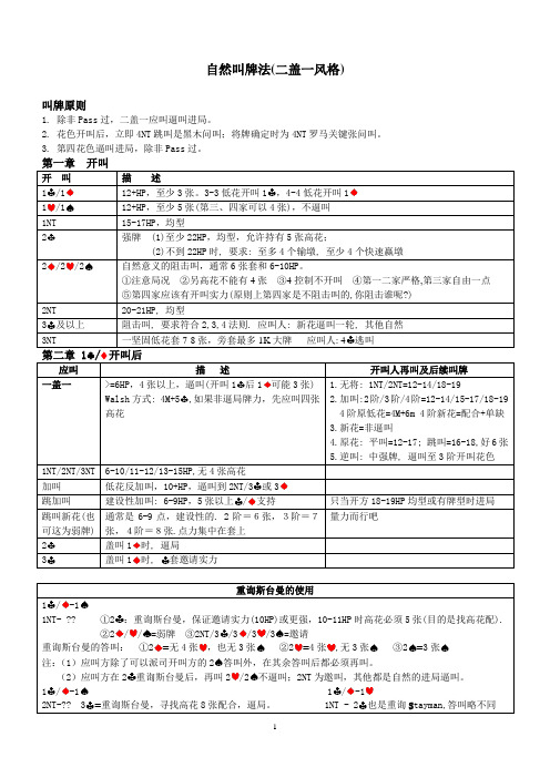
自然叫牌法(二盖一风格)叫牌原则1. 除非Pass过,二盖一应叫逼叫进局。
2. 花色开叫后,立即4NT跳叫是黑木问叫;将牌确定时为4NT罗马关键张问叫。
3. 第四花色逼叫进局,除非Pass过。
11122/23: 4逃叫1: 4M+52NT/3张以上/2时3时套邀请实力1-1:重询斯台曼,保证邀请实力/=2NT/3/3/3=张2张张22/21-1-12NT-?? 3 1NT - 21 1.2张: 1,2,4M+52/34=。
/32/3344=2 44,22/3:低限弱套:低限好套3333:3张3张43 344/第二部分竞叫与信号一、同伴开叫,敌叫牌后应叫人的处理方法1、一阶花色开叫被加倍后: ①无将=自然②一阶新花=逼叫,二阶新花=不逼叫③加叫=正常或更低④跳加叫=阻击⑤XX=好牌2、一阶花色开叫敌争叫后: ①加倍=负加倍(不高于3或4),6点以上②无将=自然③新花=逼叫一轮④加叫=正常⑤跳加叫=阻击⑥扣叫=限制性加叫或更好3、一阶花色开叫敌争叫1NT后:①加倍=9点以上,惩罚性②其他=自然4、1NT开叫对方加倍后①再加倍=SOS ②二阶=弱套③三阶=邀请实力④PASS=弱牌或有实力5、1NT开叫对方二阶争叫后①加倍 = 技术性②二阶新花 = 不逼叫,至少5张③三阶低花 = 邀叫以上④三阶高花 = 5张套,敌花无止,逼局⑤扣叫 = Stayman,敌花无止,逼局⑥3NT = 无4张高花,敌花无止⑦ 2NT:莱本索尔约定叫(开叫人必须叫3), 应叫人再叫如下:a.PASS或3都是弱牌b.敌争2后叫3为邀请叫c.扣叫=另高花4张且敌花有止,逼局d.新高花=5张且敌花有止,逼局e.3NT=无4张高花,敌花有止,止叫二、防御方叫法1、简单争叫:自然2、跳争叫:弱争叫3、争叫1NT:同开叫1NT3、米切尔扣叫:扣叫低花为两高花,扣叫高花表示另一高花及一低花;一般争叫实力或略低4、跳争2NT:特殊无将,表示双低花,实力同米切尔扣叫5、加倍:技术性,不超过3(也可约定至4或4)6、对1NT开叫:加倍=惩罚性;2=Landy争叫,表示双高;其他=自然争叫7、平衡位置:争叫1NT=13-15点;加倍=可以低于开叫实力,牌型限制不严;争叫=可以低1K左右8、对付强1开叫(也可用于1-1后):①加倍=至少5-4高花套②1NT=至少5-4低花套③2/3NT=两低套④1///2=好套⑤跳争叫=阻击叫⑥不叫=弱牌或均型强牌三、竞争叫牌可选用约定叫1、支持性加倍。
哥 老 会

2、外八堂
一排心腹(负责招待同党) 一排心腹(负责招待同党) 二排圣贤(为军师,以关羽居二,通常不封普通兄弟, 二排圣贤(为军师,以关羽居二,通常不封普通兄弟,而 以位置和尚,在梁山为吴用) 以位置和尚,在梁山为吴用) 三排桓侯或称当家(管理会内帐目) 三排桓侯或称当家(管理会内帐目) 四排金凤(也称金姊、四姊) 四排金凤(也称金姊、四姊) 五排红旗(负责组织,辖蓝旗、黑旗,协助捉人执法) 五排红旗(负责组织,辖蓝旗、黑旗,协助捉人执法) 六排巡风(负责巡逻) 六排巡风(负责巡逻) 七排银凤(也称银妹、七妹) 七排银凤(也称银妹、七妹) 八排先锋大爷(负责刺探消息) 八排先锋大爷(负责刺探消息) 九排江口大爷(负责口岸) 九排江口大爷(负责口岸) 十排大满、小满、铜章、铁印(负责招待、通风报信)。 十排大满、小满、铜章、铁印(负责招待、通风报信)。
《海底》 海底》
“海底名称,由永宁郭永泰开荩忠山始。永泰先世为云南 海底名称,由永宁郭永泰开荩忠山始。 大理府人,常随父执贩药材走滇黔山中, 大理府人,常随父执贩药材走滇黔山中,以故与滇黔豪 杰善。道光十五年,省其叔于福建之厦门,遭暑。 杰善。道光十五年,省其叔于福建之厦门,遭暑。暇时出 游,偶憩民家,见其盖米瓮有旧书一本,面署《金台山 偶憩民家,见其盖米瓮有旧书一本,面署《 实录》五字,书面盖有长方形图章一颗,文曰‘ 实录》五字,书面盖有长方形图章一颗,文曰‘延平郡 王招讨大将军’ 知系郑成功遗物,问所由来, 王招讨大将军’。知系郑成功遗物,问所由来,自言伊 父生时业渔,善泅水,能于水中伏一昼夜, 父生时业渔,善泅水,能于水中伏一昼夜,于海底得一 铁匣,苦无法揭视。竭三日之力.始将铁匣凿开。 铁匣,苦无法揭视。竭三日之力.始将铁匣凿开。内贮 金珠数件,小玉印一方,旧书一本,余无他物。 金珠数件,小玉印一方,旧书一本,余无他物。因不识 不悉何书。永泰以百钱购得,并问玉印安在? 字,不悉何书。永泰以百钱购得,并问玉印安在?答以 售与邻某。永泰又以白银十两赎回,从此, 售与邻某。永泰又以白银十两赎回,从此,《金台山实 并小玉印,落入永泰之手。道光二十八年, 录》并小玉印,落入永泰之手。道光二十八年,郭永泰 等开荩忠山,所传各令,并汉留组织之秘密书, 等开荩忠山,所传各令,并汉留组织之秘密书,即名 海底》 又名《金不换》 当时各会员所领证书. 《海底》,又名《金不换》。当时各会员所领证书.均 盖有‘延平郡王招讨大将军印’十字。 盖有‘延平郡王招讨大将军印’十字。其证书至今尚有 存者, 金台山实录》与郑成功之小玉印, 存者,惟《金台山实录》与郑成功之小玉印,因遭太平 天国之乱,不知下落。 ——刘师亮 汉留全史》 刘师亮《 天国之乱,不知下落。”——刘师亮《汉留全史》
帮派系统

帮派概述帮派是游戏中志同道合的玩家组成的大家庭。
【帮派功能】(1)每个帮派拥有自己的集会场所和帮派频道。
(2)帮派成员可以在帮中学习各种辅助技能,以提高自己的生存和竞争能力。
(3)帮派成员可参加帮派特有的任务、活动。
(4)帮派成员可获得各种福利,比如领取帮派礼物、领取帮派工资、购买药品等。
【建立帮派】(1)等级达到20级的无帮派人士,可在长安城“帮派总管”处申请创建帮派。
(2)申请成功后,24小时内响应人数达到20,则帮派创建成功,申请者为帮主、响应者为帮众。
(3)24小时期满响应人数少于20则建帮失败,手续费不退还。
【加入帮派】等级达到11级的无帮派人士可在帮派总管处申请加入帮派,或由有帮人士推荐入帮;帮主、副帮主和长老可接收申请入帮的玩家。
帮派属性帮派规模:即帮派等级。
影响到各种帮派建筑的等级上限,是帮派竞争力的最直观体现。
敌对帮派:由帮主设定的敌对关系的帮派。
设置敌对帮派是进行朱雀堂任务的前提。
帮派资金:帮派的可用资金,是维持帮派正常运转的必需条件。
资金不足会导致帮派规模下降。
特别注意:当帮派规模为1时,若规模下降则帮派会解散。
总资产:对帮派资产的整体估价。
是帮派综合实力的衡量指数。
繁荣度:帮派的繁荣程度,帮众完成部分任务可获得;帮派规模提升、帮派建筑等级提升时需要消耗一定的繁荣度。
安定度:帮派的安定程度,帮众完成部分任务可获得;敌对帮派成员前来捣乱会导致安定度下降。
安定度降低会导致帮派研究技能的速度减慢。
人气度:体现帮派人气是否旺盛的指数。
帮众在线可提高帮派人气(本级收益次数有三项达到上限的帮派成员不增加帮派人气);每小时维护时根据帮派规模扣除一定人气。
人气不足会导致帮派规模下降。
特别注意:当帮派规模为1时,若规模下降则帮派会解散。
行动力:帮派行动能力,用于帮派活动等消耗。
每周清零后根据上周获得的帮派威望重新计算行动力。
帮派威望:所有帮派成员的威望总和。
帮派行动力的主要来源。
成员数量:帮派当前成员的人数。
联众完美学习手册
第二:几个必须知道的功能。
敲桌子:先点(鼠标左键双击)你要喊的人的名字,然后你点击下面聊天命令
中的‘hurry“,再发出。就可以发出敲桌子的声音,只有被敲的人听到呼
叫:比如你在某个游戏室看见朋友挂在那里,但是他可能再玩别的游戏,看
不到你,你要叫醒他,就可以选取你要呼叫的人,点“beep“命令,就能发
修改注册资料:/regist/changeinfo.html
服务中心:/srvce
理财中心:/srvcenter/bank/
江湖论坛:/forum/
千里眼
【功能说明】使用此功能可以使您不管处在联众世界的任何游戏室,都可以
找到您的朋友
【使用格式】`search username
`
在键盘的左上角与字符“~”同一个按键;username 是对方用户名。
【举例】要寻找我小甜妞[mskn],就写:
`
search mskn
在比赛需要记录比分中或者游戏中出现问题的时候,为了留下实物证
据,可以采用抓图的方法记录,具体操作方法如下:
当问题出现时,要果断的选好最能说明问题的画面,迅速按下键盘上的
“print scrn sys rq”键,当你按下这个键的时候其实图已经抓到了,下
面就要给你抓的图一个载体,用鼠标点击左下角的“开始”然后按“开始”
联众会员可能运用聊天的基本功能进行编辑,输入到前缀、出入语等功能
中,来增加聊天的乐趣。
具体方法:在游戏大厅中点击右下角的设置功能,在进入、退出、前缀中分
别输入事先编辑好的聊天字符。
例如:《f=宋体,c=#ff#00#00,s=17,》欢迎加盟:****QQ:xxxxxx即为红
堂堂网的注册及使用

网址:/
方法:打开浏览器,在地址栏中输入网址,按回车键。
注册方法1:
单击此处进行注册
注册方法1:
输入信息完成注册
注册方法2:
用QQ号注册
注册方法2:
输入QQ号及QQ密码。 单击授权并登录按钮。
单击பைடு நூலகம்转。
注册方法2:
输入信息,单击提交完 成注册。
使用:
选择相应的学科。
使用:
择版本 及年级,最后选择课程。
使用:
择版本 及年级,最后选择课程。 单击授课,进行教学。
使用:
单击这几个按钮可进行选择教学过程。
使用:
选择相应项目。
使用:
播放相应的资源
使用:
生字书写。
使用:
语段精读。
20882930_江湖春典“入”家办
南春、北典即江湖行话,本系老年间士农工商之外的各色人等混生计时用的只限本行本业内部沟通的专业术语,行外人则称之为“黑话”,因其体现专业价值之余又占了信息不对等、抬高认知门槛的便宜而被该领域内人士奉为至宝,就有了“宁给一锭金,不教一句春”的古训。
而在众人拾柴、心比天高的家办行业,在傲视财富管理的最巅峰处,竟然有人自贬身份四处公开分享、大众培训、廉价课程,甚至还开了网课,这、这、这简直是挖人祖坟、坏人风水、数典忘祖、忘八端……(此处省略三五百字文雅谴责)。
难怪有人放出话来,“有空讲课的都是没客户的,有实务敢实操的都忙着呢!”只因任何一个非标行业,与客户达成交易前的你来我往,都是极其重要的吃饭本领,是平地扣饼、对面拿贼的神兵利器。
就像中医说不出“脾胃土败,命门血衰,气血两虚”就没法好好坐堂听诊一样,家族办公室行业也有几句易学好用的真言,怕就怕世人本就鲁钝不识真佛,极易被盗去几句真经的歪和尚带入邪道,神坛上金身无缘贡奉,忍饥挨饿之下涵养再好也很难不把嗔戒犯了再犯。
不过话又说回来,FO行业话术门槛的迅速降低也不能只怪那些以教育市场之名四处获客的人吃相难看,还得怨家办本身的“黑话”太幼齿,入门级的专业词涵加起来少则二三十,多不过七八十,用百来个词撑起数以万亿计的私人财富大旗,其词汇量委实太过单薄。
略有心机的,随便花个三天两早晨功夫串串词再加几分个人理解、引用些海外数据佐证,如果顺口无心地透露自己与某个大家族暗通款曲就更加完美,然后或托人或花钱上几个峰会混几次论坛,不用几个月就算正式出道,可以招摇过市充当传承专家了。
幸而还有国际金融、跨境法律、海内外税筹等极吃专业的方面撑在后面作为最后的,不然FO 早被这些有的没的“异鬼”屠城了。
但是专业到这个级别的话术超出客户理解范畴太多,完全没有几句春典的效果好,既新鲜又能拉近关系,比如跟客户讲北京流氓为啥管姑娘叫“果儿”,“果儿”脸漂亮身材好,得说“盘亮”、“条顺”,于戏谑中陡增身份。
预言Online——帮众称号与帮主权利
预⾔Online——帮众称号与帮主权利 【帮众称号】 每个帮会成员都可以有⾃⼰的称号,帮派护法、堂主的称号都必须由帮主修改,玩家⾃⼰没有权限更改。
1、帮会刚成⽴时,帮主的称号为“帮主”。
2、帮主可以通过赋权来修改帮会成员权限。
3、帮主可以任命副帮主来⾏使部分帮主权限。
4、帮主可以让位给其他公会成员,如果帮主让位给玩家,则那位公会成员成为新帮主。
职位⼈数限制: 1:帮主:可设1⼈。
2:副帮主:可设2⼈。
3:护法:可设置4⼈。
4:堂主:可设置8⼈。
5:帮众:其余的都是。
【帮主权⼒】 ⼀、职位与权利对应列表: 帮主:1:收⼈权限、2:开除权限、3:编辑公告权限、4:增加联盟、5:删除联盟、6:增加敌对、7:删除敌对、8:更改阶层、9:接受联盟,11:转让帮派会主,13:申请会战权限,12:缔结参战联盟,1 5:接受会战申请、16:解除参战联盟,17:删除帮派仓库物品 ⼆、权利列表: 1:收⼈权限:添加其他玩家进⼊帮派。
2:开除权限:将帮派成员开除出帮。
3:编辑公告:发布和修改帮派公告的内容。
4:增加联盟:增加帮派盟友。
5:删除联盟:删除帮派盟友。
6:增加敌对:增加敌对势⼒。
7:删除敌对:删除敌对势⼒。
8:更改阶层:更改帮派成员的职位。
9:接受联盟:接受对⽅提出的联盟请求。
10:退帮权利:退出当前所在的帮派,帮主退帮前必须指定继任帮主,否则不允许帮主退帮。
11:转让帮主:将帮主职位转让给40级(包含40级)以上的帮会成员。
12:缔结参战联盟:和其他帮派⼀起缔结攻防协议。
13:申请会战权限:申请和其他帮派进⾏会战。
14:申请领地争夺战:到N P C“领地⼤使”那⾥申请进⾏领地争夺帮战。
15:接受会战申请:接受其他帮派的会战申请。
16:解除参战联盟:解除和其他帮派的攻防协议。
三:副帮主: 1:收⼈权限、3:编辑公告权限:4:增加联盟、5:删除联盟、6:增加敌对、7:删除敌对、10:退出帮派 四:护法:1:收⼈权限、:4:增加联盟、5:删除联盟、9:退出帮派 五:堂主:1:收⼈权限、:4:增加联盟、9:退出帮派 六:帮众:9:退出帮派 逗游⽹——中国2亿游戏⽤户⼀致选择的”⼀站式“游戏服务平台。
- 1、下载文档前请自行甄别文档内容的完整性,平台不提供额外的编辑、内容补充、找答案等附加服务。
- 2、"仅部分预览"的文档,不可在线预览部分如存在完整性等问题,可反馈申请退款(可完整预览的文档不适用该条件!)。
- 3、如文档侵犯您的权益,请联系客服反馈,我们会尽快为您处理(人工客服工作时间:9:00-18:30)。
《古惑仔online》堂口系统介绍
横板格斗动作手游《古惑仔online》官方正版授权,经典电影重现!通过讲述陈浩南、山鸡等原著人物的恩怨情仇、爱恨纠葛,为玩家打造一个热血激情的游戏世界。
炫酷的技能特效,打击手感爽到爆表;忠于原著的剧情,代入感十足,斩靓坤、斗乌鸦,让人血脉愤张;经典人物悉数登场,山鸡浩南在等着你携手重战江湖!
《古惑仔online》堂口系统介绍,一起来看看吧
十三妹又来了~~,对于在古惑仔江湖中征战的扛把子来说,最重要的是结交一群“不求同年同月生,但求同年同月死“的兄弟,和朋友们一起享受游戏带来的乐趣。
登登登登!!那如何在《古惑仔》世界里结交这些过命的兄弟呢,各位扛把子可以在我们全新登场的堂口系统寻找这些志同道合的难兄难弟!!下面就由我十三妹给各位介绍吧!
1.堂口系统开放介绍
玩家等级20级以上并且通关痛打笑面虎这个任务以后开放,无堂口的玩家可以创建或者申请加入一个公会,创建堂口需消耗一定的钻石。
2.堂口系统等级介绍
堂口和堂口工坊都拥有自己的等级,
升级堂口需要消耗一定数量的堂口贡献和金币,堂口升级后堂口工坊等级上限和可加入堂口
人数上限会增加
3.堂口成员头衔与职务介绍
堂口职务包括堂主、副堂主与无职务成员。
一个堂口可以拥有1个堂主、2个副堂主。
堂主与副堂主可以进行升级堂口工坊升级、升级堂口技能、踢出堂口成员、修改堂口公告、批准或拒绝成员加入、修改堂口图标等。
堂主可以进行任命副堂主、罢免职位、转让堂主、解散堂口。
堂口工坊:
随着堂口不断升级,伴随堂口等级提高,堂口成员可以享受的堂口福利也随之增加。
还有别忘了提升堂口工坊技能哦。
堂口商城:
更多手机游戏攻略,敬请关注百度攻略&搞趣网攻略频道!。
