倍加福NBB1.5-8GM50-E2
模块检验项目
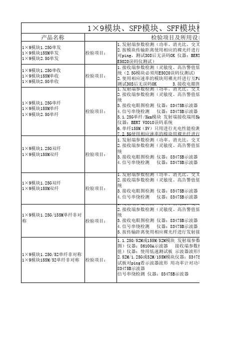
1×9模块1.25G/52单纤非对称 1×9模块155M/52单纤非对称 检验项目:
1.发射端参数检测(功率、消光比、交叉点、眼图)仪器:86100 2.接收端参数检测(灵敏度、高告警值低告警值)仪器:BERT V8 统 3.接收电眼图检测 仪器:83475B示波器 4.信号串绕检测 仪器:83475B示波器 5.按传输距离使用相应裸光纤进行发射接收视频传输 图象必须没 1.1.25G/52M或155M/52M模块 发射端参数检测(功率、消光比、交 图)仪器:86100A示波器 接收端参数检测(灵敏度、高告警值 值)仪器:使用低速测试板 示波器波形判定 2.52M/1.25G或52M/155M模块仪器:83475B示波器 发射参数检测( 试板对ping看示波器波形 用功率计对功率值 接收电眼图检测 仪 83475B示波器 信号串绕检测 仪器:83475B示波器
光比、交叉点、眼图)仪器:86100A示波器 高告警值低告警值)仪器:BERT V8010误码系 3.3V工作电 压
75B示波器 75B示波器 的核对) 接收端用5km裸光纤传输10S无误码丢包率OK
件检测:偏置电流、光功率、接收功率是否校
光比、交叉点、眼图)仪器:86100A示波器 高告警值低告警值)仪器:BERT V8010误码系
75B示波器 75B示波器 的核对) 光比、交叉点、眼图)仪器:86100A示波器 高告警值低告警值)仪器:BERT V8010误码系
3.3V工作电 压
75B示波器 75B示波器 的核对)
3.3V工作电 压
F模块检验项目
备注
及所用设备
光比、交叉点、眼图)仪器:86100A示波器 用于任何接 裸光纤进行互Ping,如25KM用30KM裸光纤进行 口类型、 仪器:BERT V8010误码系统(2.5G模块必须用 3.3V和5V模 块 高告警值低告警值)仪器:BERT V8010误码系 用于任何接 码仪测试) 口类型、 纤进行互Ping,如25KM用30KM裸光纤进行ping 3.3V和5V模 接收电眼图检测 仪器:83475B示波器 块 光比、交叉点、眼图)仪器:86100A示波器 高告警值低告警值)仪器:BERT V8010误码系 除单纤155M (5V)外用 75B示波器 于任何接口 75B示波器 接收端用5km裸光纤传输10S无误码丢包率OK 类型、3.3V 和5V模块 电性能检测、接收眼图检测、信号串绕检测 裸光纤进行互Ping必须用E5020误码仪测试 光比、交叉点、眼图)仪器:86100A示波器 高告警值低告警值)仪器:BERT V8010误码系 用于任何接 口类型、 75B示波器 3.3V和5V模 75B示波器 块
E H仪器仪表价格选型报价
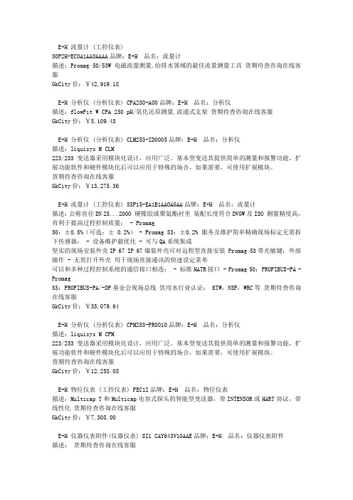
E+H 流量计 (工控仪表)50P2H-EC0A1AA0AAAA品牌:E+H 品名:流量计描述:Promag 50/53W 电磁流量测量,给排水领域的最佳流量测量工具货期待查咨询在线客服GkCity价:¥42,919.18E+H 分析仪 (分析仪表) CPA250-A00品牌:E+H 品名:分析仪描述:flowFit W CPA 250 pH/氧化还原测量,流通式支架货期待查咨询在线客服GkCity价:¥5,109.43E+H 分析仪 (分析仪表) CLM253-ID0005品牌:E+H 品名:分析仪描述:liquisys M CLM223/253变送器采用模块化设计,应用广泛。
基本型变送其提供简单的测量和报警功能,扩展功能软件和硬件模块化后可以应用于特殊的场合,如果需要,可使用扩展模块。
货期待查咨询在线客服GkCity价:¥13,275.36E+H 流量计 (工控仪表) 53P15-EA1B1AAOAGAA品牌:E+H 品名:流量计描述:公称直径DN 25...2000 硬橡胶或聚氨酯衬里装配长度符合DVGW及ISO 测量精度高,有利于提高过程控制质量: - Promag50:±0.5%(可选:± 0.2%) - Promag 53:±0.2% 服务及维护简单精确现场标定无需拆下传感器: - 设备维护最优化 - 可与QA系统集成坚实的现场安装外壳IP 67 IP 67墙装外壳可对远程型直接安装 Promag 53带光敏键:外部操作 - 无需打开外壳用于现场直接通讯的快速设定菜单可以和多种过程控制系统的通信接口相连: - 标准HATR接口 - Promag 50:PROFIBUS-PA - Promag53:PROFIBUS-PA/-DP基金会现场总线饮用水行业认证: KTW,NSF,WRC等货期待查咨询在线客服GkCity价:¥35,079.64E+H 分析仪 (分析仪表) CPM253-PR0010品牌:E+H 品名:分析仪描述:liquisys M CPM223/253变送器采用模块化设计,应用广泛。
FB系列产品价格一览表
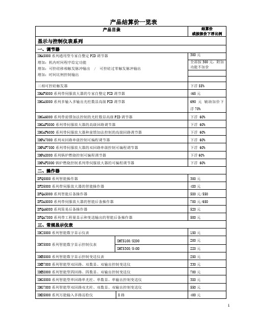
2
低差压/DP
3S
0~1.3~7.5
2000
3
中差压/DP
4S、5S、6S
0~6.2~690
2000
4
大差压/DP
7S
0~345~2068
2000
5
低压力/GP
3S
0~1.3~7.5
2000
6
中压力/GP
4S、5S、6S、7S、8S
0~6.2~6890
2000
7
高压力/GP
9S、0S
0~3450~41370
铠装式热电偶
下浮8 %
WR隔爆热电偶(dIIBT4)
下浮8 %
WZP隔爆热电阻(dIIBT4)
下浮8 %
高、中、低压热套热电偶
下浮8 %
炉壁热电偶
下浮8%
WSS系列双金属温度计
下浮10%
四、分析仪表
S400工业过程PH/ORP检测电极
下浮30 %
PHAB5000系列PH/ORP值显示控制、变送、调节输出专用仪表
下浮60 %
XMS5000系列速度显示控制变送仪表
350
四、流量仪表
XMJ5000系列智流量积算显示控制仪表
450元
XML5000系列补偿式流量积算显示控制仪表
600元
XMLH5000系列热水热量积算仪表
1450元
XMLH6000系列蒸汽热量积算仪表
1450元
五、特殊场合专用仪表
XMG8000系列压力补偿式锅炉汽包水位光柱数显控制变送仪
规格
结算价
1
FB0803工业型
(普通本安型)
0-5~20
A
500
取样探头 222.15 17 20 21 31 35 安装及使用说明书

取样探头222.15/17/20/21/31/35安装及使用说明书BC460017, 07/2017 Art. Nr. 90 31 059Bühler Technologies GmbH, Harkortstr. 29, D-40880 RatingenTel. +49 (0) 21 02 / 49 89-0, Fax. +49 (0) 21 02 / 49 89-20AP000005请在安装和使用前仔细阅读此手册。
敬请特别注意所有安全守则,以避免不必要的意外伤害事故。
Bühler Technologies GmbH /德国比勒科技有限责任公司对由不当操作以及在未授权情况下擅自改动机器设备所引起的后果不承担任何责任。
目录页1概述 (4)2重要注意事项 (4)2.1安全注意事项概述 (5)3铭片说明 (6)4产品说明 (6)4.1概述 (6)4.2发货内容 (6)5运输及存储要求 (7)6安装及线路连接 (7)6.1安装 (7)6.2探管的连接 (8)6.2.1样气管的连接 (9)6.2.2校正气体管的连接(可选) (9)6.3反吹和反吹气罐的连接(适用于 GAS 222.21, 31 和 35) (9)6.4电子线路连接 (10)6.4.1型号 GAS 222.15 / GAS 222.17 (10)6.4.2型号 GAS 222.20, 21, 31, 35 (10)6.4.3加热反吹气罐(可选) (11)6.4.4加热扩展件(可选) (11)7操作与维护 (11)7.1安全条款 (11)7.2操作前请检查 (12)7.3探头GAS 222.20, 21, 31, 35 上控制器的功能 (13)7.3.1所有控制器的功能 (13)7.3.2加热扩展件的内置控制器的更多功能(可选) (13)7.3.3内置反吹控制器的功能 (13)7.3.4附加PCB电路板用于电磁阀和限位开关(可选电磁阀控制板) (13)7.4滤芯的维护: (13)7.4.1带顺流过滤器的探头GAS 222.15 (13)7.4.2使用玻璃纤维滤芯的顺流过滤器 (14)7.4.3带顺流过滤器的探头GAS 222.17, 20 和 21 (14)7.4.4带直插过滤器的探头GAS 222.21, 31 和 35 (15)7.5工艺管道中直插过滤器的反吹 (16)7.5.1手动反吹 (16)7.5.2自动反吹 (16)7.5.3内置反吹控制器 (17)7.6控制器的设置 (18)7.6.1菜单选项 (18)7.6.2操作原则详述 (19)7.6.3菜单功能说明 (20)7.6.3.1主菜单 (20)7.6.3.2探头控制器的子菜单(Display: Prob) (21)7.6.3.3加热扩展件控制器的主菜单(display: Adon) (可选) (21)7.6.3.4反吹控制器的子菜单(display: bbc) (可选) (22)8故障及故障排除 (23)8.1备件 (24)9维修及报废处理 (24)9.1报废处理 (24)10制图,证明,数据表 (25)10.1接线图 GAS 222.15/17 (25)10.2接线图 GAS 222.20, 21, 31, 35 (26)10.3加热气罐的连线图 (27)10.4附加文件 (27)1 概述GAS 222.xx系列探头设计安装于气体分析系统内部。
派克液压密封件说明书

派克汉尼汾公司版权所有未经许可不能摘录,翻印。
保留修改权利2021年6月警告销售条件本样本中产品和/或系统或相关产品出现故障,选型不当或使用不当,均可能导致人身伤亡和财产损失。
本文档以及由派克·汉尼汾公司及其子公司和授权经销商提供的其他资料,为具有技术知识的用户提供进一步研究所需的产品和/或系统选项。
重要的是,用户必须对您的应用进行全面的分析,并对当前产品样本中与产品或系统相关的资料进行评估。
由于工作条件以及产品或系统的多样性,用户必须自行分析和测试,并独自承担一切后果,包括:产品和系统的最终选型以及确保满足应用的所有性能、安全和警告等方面的要求。
派克·汉尼汾及其子公司可能会随时对本样本中的产品,包括但不限于:产品的特性、产品的规格、产品的结构、产品的有效性以及产品的价格作出变更而不另行通知.本样本中的所有产品均由派克·汉尼汾公司及其子公司和援权经销商销售。
与派克签订的任何销售合同均按照派克标准条件和销售条件中规定的条款执行(提供复印件备索)。
本公司的密封件,只能在本公司的文件资料述及的应用参数范围与接触介质、压力、温度和存放时间相一致的情况下才能使用。
在规定的应用参数范围外使用以及错误选用不同的材料都可能导致密封件寿命的缩短以及设备的损坏,甚至更严重的后果(如生命安全,环境污染等)。
样本中所列出的工作压力、温度范围、运动速度是极限值,它们之间相互关联、相互影响;在极端的工况下,建议不要同时把各个参数都同时用到极限值。
对于特殊的要求(压力、温度、速度、介质等),请联系派克汉尼汾公司以咨询合适的密封结构、材料、配置、安装建议等。
由于诸多工作参数会影响到流体传动系统及密封元件,这些设备的制造商必须在实际工作条件下测试、验证并批准密封系统的功能与可靠性。
此外,对于不断出现的新的介质(液压油、润滑脂、清洗剂等),用户特别注意它们与目前所用的密封件弹性体材料的兼容性。
我们建议用户在大批量应用之前,在厂内或现场先做密封材料的兼容性能测试,作为密封产品与系统供应商,我们建议用户遵循我们的这些建议。
多功能机械辅助系统安装维护与配件手册说明书

For other service manuals visit our website at:/service_manuals.aspDORNER MFG. CORP .INSIDE THE USA OUTSIDE THE USA P .O. Box 20 • 975 Cottonwood Ave.TEL: 1-800-397-8664TEL: 262-367-7600Hartland, WI 53029-0020 USA FAX: 1-800-369-2440FAX: 262-367-5827851-260 Rev. J2100, 2200, 4100, 6200 and MPB Series Bottom Mount Drive Package for Light Load60 Hz GearmotorsInstallation Maintenance & Parts ManualDorner Mfg. Corp.2851-260 Rev. J2100, 2200, 4100, 6200 and MPB Series Bottom Mount Drive Package for Light Load 60 Hz Gearmotors Table of ContentsIntroduction......................................................................... 2Warnings − General Safety ................................................. 3Product Description............................................................. 4Specifications...................................................................... 4Installation........................................................................... 7Required Tools................................................................. 7Mounting.......................................................................... 7Preventive Maintenance and Adjustment.......................... 10Required Tools............................................................... 10Timing Belt Tensioning. (10)Timing Belt Replacement .............................................. 10Drive or Driven Pulley Replacement ............................ 11Gearmotor Replacement ................................................ 11Service Parts....................................................................... 142100, 2200, 4100, 6200 Series and MPB SeriesLight Load Bottom Mount Drive Package .................... 144100 Series Adapter Package ........................................ 15Gearmotors..................................................................... 15Return Policy. (16)IntroductionUpon receipt of shipment:•Compare shipment with packing slip. Contact factory regarding discrepancies.•Inspect packages for shipping damage. Contact carrier regarding damage.•Accessories may be shipped loose. See accessory instruc-tions for installation.Dorner 2100 Series conveyors are covered by the following patent numbers: 5131529, 5174435, and corresponding patents and patent applications in other countries.Dorner 2200 and MPB Series conveyors are covered by patent number 5174435 and corresponding patents and patent applications in other countries.Dorner 4100 Series conveyors are covered by patent number 3923148 and corresponding patents and patent applications in other countries.Dorner 6200 Series conveyors are covered by patent number 6685009, 5174435, 6109427 and corresponding patents and patent applications in other countries.Dorner’s Limited Warranty applies.Dorner reserves the right to make changes at any time without notice or obligation.Dorner has convenient, pre −configured kits of Key Service Parts for all conveyor products. These time saving kits are easy to order, designed for fast installation, and guarantee you will have what you need when you need it. Key Parts and Kits are marked in the Service Parts section of this manual with the Performance Parts Kits logo .IMPORTANTSome illustrations may show guardsremoved. Do NOT operate equipment without guards.851-260 Rev. J3Dorner Mfg. Corp.2100, 2200, 4100, 6200 and MPB Series Bottom Mount Drive Package for Light Load 60 Hz Gearmotors Warnings − General SafetyA WARNINGThe safety alert symbol, black triangle with white exclamation, is used to alert you to potential personal injury hazards.Climbing, sitting, walking or riding onconveyor will cause severe injury. KEEP OFFCONVEYORS.DO NOT OPERATE CONVEYORS IN AN EXPLOSIVE ENVIRONMENT.Hazardous voltage will cause severe injury ordeath. LOCK OUT POWER BEFORE WIRING.A WARNINGGearmotors may be HOT.DO NOT TOUCH Gearmotors.A WARNINGExposed moving parts can cause severe injury. LOCK OUT POWER before removingguards or performing maintenance.A WARNINGDorner cannot control the physicalinstallation and application of conveyors. Taking protective measures is the responsibility of the user.When conveyors are used in conjunction with other equipment or as part of a multiple conveyor system, CHECK FOR POTENTIAL PINCH POINTS and other mechanical hazards before system startup.A WARNINGMPB Series Conveyors are not reversible. Reversing creates pinch points which can cause severe injury.DO NOT REVERSE MPB SERIES CONVEYORS.Dorner Mfg. Corp.4851-260 Rev. J2100, 2200, 4100, 6200 and MPB Series Bottom Mount Drive Package for Light Load 60 Hz Gearmotors Product DescriptionRefer to Figure 1 for typical components.Figure 1SpecificationsGearmotor Mounting Package Models:Example:* See “Ordering and Specifications” Catalog for details.A ConveyorB Mounting BracketC GearmotorD Belt TensionerE CoverF Timing BeltG Drive Pulley HDrivenPulleyABCDEFGH Single PhaseDC Variable Speed Output Power 0.03 hp (0.025 kw)0.06 hp (0.04 kw)Input Voltage 115 Volts A.C.130 Volts D.C.Input Frequency 60 Hz N/AFull Load Amperes 0.49 Amperes 0.48 Amperes Gearmotor Ratios15:1 and 36:118:1 and 60:1851-260 Rev. J5Dorner Mfg. Corp.2100, 2200, 4100, 6200 and MPB Series Bottom Mount Drive Package for Light Load 60 Hz Gearmotors SpecificationsTable 2: Belt Speeds for Light Load Fixed Speed Parallel Shaft 60 Hz Gearmotors on 2100, 2200 Gang Drive, 4100 and 6200 Series Conveyors* 115V , 1 phase, non −reversingTable 3: Belt Speeds for Light Load Fixed Speed Parallel Shaft 60 Hz Gearmotors on 2200 Series Conveyors (Excluding Gang Drive)* 115V , 1 phase, non −reversingTable 4: Belt Speeds for Standard Load Fixed Speed Parallel Shaft 60 Hz Gearmotors on MPD Series Conveyors* 115V , 1 phase, non −reversingTable 5: Belt Speeds for Light Load Variable Speed Parallel Shaft DC Gearmotors on 2100, 4100 and 6200 Series Conveyors* 130VDCGearmotors *Belt Speed Drive Pulley Driven Pulley Part Number Gear RatioRPM In-lb N-m Ft/min M/min 62M036PL4FN 36:14236 4.18 2.4223262M036PL4FN 36:14236 4.112 3.7323262M036PL4FN 36:14236 4.117 5.2322262M036PL4FN 36:14236 4.1247.3442262M015PL4FN 15:110015 1.7298.8323262M015PL4FN15:1100151.74112.53222Gearmotors *Belt Speed DrivePulley Driven Pulley Part Number Gear RatioRPM In-lb N-m Ft/min M/min 62M036P L 4FN 36:14236 4.1 134.0283262M036PL4FN 36:14236 4.115 4.6282862M036PL4FN 36:14236 4.121 6.4322262M036PL4FN 36:14236 4.1298.8442262M015PL4FN 15:110015 1.73510.7282862M015PL4FN15:1100151.75516.84428Gearmotors *Belt Speed Drive Pulley Driven Pulley Part Number Gear RatioRPM In-lb N-m Ft/min M/min 62M036PL4FN 36:14236 4.1257.5283262M036PL4FN 36:14236 4.1288.6282862M036PL4FN 36:14236 4.14513.6442862M036PL4FN36:142364.15717.34422Gearmotors *Belt Speed Drive Pulley Driven Pulley Part Number Gear RatioRPM In-lb N-m Ft/min M/min 62M060PLD3DEN 60:142657.4 1.0−8.2.3−2.5223262M060PLD3DEN 60:142657.4 1.4−12.4−3.6323262M018PLD3DEN 18:113921 2.4 4.8−40 1.5−12323262M018PLD3DEN18:1139212.47−582.1−183222Dorner Mfg. Corp.6851-260 Rev. J2100, 2200, 4100, 6200 and MPB Series Bottom Mount Drive Package for Light Load 60 Hz Gearmotors SpecificationsTable 6: Belt Speeds for Standard Load Variable Speed Parallel Shaft DC Gearmotors on 2200 Series Conveyors (Excluding Gang Drive)Table 7: Belt Speeds for Standard Load Variable Speed Parallel Shaft DC Gearmotors on MPB Series Conveyors* 130VDCGearmotors *Belt Speed Drive Pulley Driven Pulley Part Number Gear RatioRPM In-lb N-m Ft/min M/min 62M060PLD3DEN 60:142657.4 1.8−14.5−4.5282862M060PLD3DEN 60:142657.4 2.8−23.8−7442862M018PLD3DEN 18:113921 2.46−49 1.8−15282862M018PLD3DEN18:1139212.49−772.8−234428Gearmotors *Belt Speed Drive Pulley Driven Pulley Part Number Gear RatioRPM In-lb N-m Ft/min M/min 62M060PLD3DEN 60:142657.4 2.3−19.7−5.9223262M060PLD3DEN 60:142657.4 3.4−281−8.6282862M060PLD3DEN 60:142657.4 5.3−44 1.6−13442862M018PLD3DEN 18:113921 2.411−94 3.5−28282862M018PLD3DEN18:1139212.416−1485−454428NOTEFor belt speed other than those listed, contact factory for details.851-260 Rev. J7Dorner Mfg. Corp.2100, 2200, 4100, 6200 and MPB Series Bottom Mount Drive Package for Light Load 60 Hz Gearmotors InstallationRequired Tools•Hex key wrenches: 2.5 mm, 3 mm & 5 mm •Torque wrenchInstallation Component List:Mounting1.Typical components (Figure 2)Figure 22.Locate drive output shaft (Figure 3,item P) and remove two screws (Q).Figure 33.For your reference, the following five figures show the attachment area of complete mounting packages for the various conveyor series.2200 Series Figure 4I Bottom Mount Assembly J Driven Pulley K CoverL M4 Socket Head Screws (4x)M Timing Belt N KeyOM6 Socket Head Screws (2x)A WARNINGExposed moving parts can cause severe injury. LOCK OUT POWER before removing guards or performing maintenance.A WARNINGMPB Series Conveyors are not reversible. Reversing creates pinch points which can cause severe injury. DO NOT REVERSE MPB SERIES CONVEYORS.NOTE6200 conveyor shown, other Series similar.NKMJLOIQPDorner Mfg. Corp.8851-260 Rev. J2100, 2200, 4100, 6200 and MPB Series Bottom Mount Drive Package for Light Load 60 Hz Gearmotors Installation6200 Series Figure54100 SeriesFigure 62100 SeriesFigure 7MPB Series Figure84.Attach mount assembly (Figure 9,item I) with screws (O). Tighten screws to 80 in-lb (9 Nm).Figure95.Install key (Figure 10,item N).Figure 10A WARNINGDrive shaft keyway may be sharp.HANDLE WITH CARE.OIUNJRM851-260 Rev. J9Dorner Mfg. Corp.2100, 2200, 4100, 6200 and MPB Series Bottom Mount Drive Package for Light Load 60 Hz Gearmotors Installation6.Wrap timing belt (M) around driven pulley (J) and drive pulley (R). Install driven pulley (J) onto conveyor shaft.7.Remove cam bearing and spacer (Figure 9,item U). Place the cam bearing and spacer (Figure 11,item U) next to the driven pulley (J). Ensure the flanges of the driven pulley are aligned with the cam bearing. Tighten driven pulley set screws (T). This will allow for proper belt alignment while conveyor is in use. Replace cam bearing and spacer (U).Figure 118.Depending on direction of conveyor belt travel (1 or 2 of Figure 12), position timing belt tensioner (U) as shown. Tension timing belt to obtain 1/8” (3 mm) deflection for 1 lb (456 grams) of force at timing belt mid-point (V). Tighten tensioner screw to 106 in-lb (12 Nm).Figure 129.Install cover (Figure 13,item K) with four (4) screws (L). Tighten to 35 in-lb (4 Nm).Figure 13JT2VU1VUKLLDorner Mfg. Corp.10851-260 Rev. J2100, 2200, 4100, 6200 and MPB Series Bottom Mount Drive Package for Light Load 60 Hz Gearmotors Preventive Maintenance and AdjustmentRequired Tools•Hex key wrenches: 2.5 mm, 3 mm, 5 mm •Straight edge•Screwdriver (for terminal box screws)•Torque wrenchTiming Belt Tensioning1.Remove four (4) screws (Figure 14,item L) and remove cover (K).Figure 142.Loosen tensioner (Figure 15,item U).Figure 15 3.Depending on direction of conveyor belt travel (1 or 2 of Figure 16), position timing belt tensioner (U) as shown. Tension timing belt to obtain 1/8” (3 mm) deflection for 1 lb (456 grams) of force at timing belt mid-point (V). Tighten tensioner screw to 106 in-lb (12 Nm).Figure 164.Install cover (Figure 14,item K) with four (4) screws (L). Tighten screws to 35 in-lb (4 Nm).Timing Belt Replacement1.Remove four (4) screws (Figure 14,item L) and remove cover (K).2.Loosen tensioner (Figure 15,item U).3.Remove timing belt (Figure 17,item M).Figure 17A WARNINGExposed moving parts can cause severe injury. LOCK OUT POWER before removing guards or performing maintenance.KLLUA WARNINGExposed moving parts can cause severe injury. LOCK OUT POWER before removing guards or performing maintenance.2VU1VUTM851-260 Rev. J11Dorner Mfg. Corp.2100, 2200, 4100, 6200 and MPB Series Bottom Mount Drive Package for Light Load 60 Hz Gearmotors Preventive Maintenance and Adjustment4.Install new timing belt.5.Depending on direction of conveyor belt travel (Figure 16,item 1 or 2), position timing belt tensioner (U) as shown. Tension timing belt to obtain 1/8” (3 mm) deflection for 1 lb (456 grams) of force at timing belt mid-point (V). Tighten tensioner screw to 106 in-lb (12 Nm).6.Install cover (Figure 14,item K) with four screws (L). Tighten screws to 4 Nm.Drive or Driven Pulley Replacement1.Complete steps 1 through 3 of “Timing Belt Replacement” section on page 10.2.Loosen set screws and remove drive or driven pulley.Figure 183.Complete steps 6 through 9 of “Installation” section on page 9.Gearmotor Replacement1.For single phase motor, unplug power cord from outlet.2.For DC variable speed motor, unplug motor cord atdisconnect (Figure 19,item W).Figure 193.Remove four screws (Figure 14,item L) and remove cover (K).4.Loosen tensioner (Figure 15,item U).5.Remove timing belt (Figure 17,item M).NOTEIf timing belt does not slide over pulley flange, loosen driven pulley set screws (Figure 17,item T) and remove pulley with belt. For re-installation, see steps 6 through 9 on page 9.A WARNINGExposed moving parts can cause severe injury. LOCK OUT POWER before removing guards or performing maintenance.NOTEIf drive pulley (Figure 18,item R) is replaced, wrap timing belt (M) around drive pulley and complete step 3.RMA WARNINGExposed moving parts can cause severe injury. LOCK OUT POWER before removing guards or performing maintenance.Hazardous voltage will cause severe injury or death. LOCK OUT POWER BEFORE WIRING.NOTEIf timing belt does not slide over pulley flange, loosen driven pulley set screws (Figure 20,item T) and remove pulley with belt (M). For re-installation, see steps 6 through 9 on page 9.Dorner Mfg. Corp.12851-260 Rev. J2100, 2200, 4100, 6200 and MPB Series Bottom Mount Drive Package for Light Load 60 Hz Gearmotors Preventive Maintenance and AdjustmentFigure 206.Loosen two (2) set screws (Figure 21,item T). Remove drive pulley (R).Figure 217.Remove four screws (Figure 22,item X) and detach gearmotor.Figure 228.Mount new gearmotor with four screws (X). Tighten to 45 in-lb (5 Nm).9.Replace drive pulley (Figure 21,item R) and tighten setscrews (T).plete steps 6 through 9 of “Installation” section onpage 9.11.Replace wiring:•For a single phase motor, reverse step 1 on page 11.•For DC variable speed motor, reverse step 2 on page 11.TMRTXNotes2100, 2200, 4100, 6200 and MPB Series Bottom Mount Drive Package for Light Load 60 Hz Gearmotors851-260 Rev. J13Dorner Mfg. Corp.Dorner Mfg. Corp.14851-260 Rev. J2100, 2200, 4100, 6200 and MPB Series Bottom Mount Drive Package for Light Load 60 Hz Gearmotors Service Parts2100, 2200, 4100, 6200 Series and MPB Series Light Load Bottom Mount Drive PackageNOTEFor replacement parts other than those shown in this section, contact an authorized Dorner Service Center or the factory. Key Service Parts and Kits are identified by the Performance Parts Kits logo . Dorner recommends keeping these parts on hand.Item Part Number Description1202390M Nut, Cam Follower2450027M Drive Spacer (2100 − Cleated Belt andall 6200)450377MDrive Spacer (2100, 2200 and MPB − Flat Belt and all 4100)3450047M Cover Mounting Bracket (Flat Belt)450375MCover Mounting Bracket (Cleated Belt and MPB)4200376M Drive Guard (Flat Belt)450376M Drive Guard (Cleated Belt and MPB)5450046M Light Duty Motor Mount Plate − Short (Flat Belt, except MPB)450026MLight Duty Motor Mount Plate (Cleated Belt and MPB)6450445Spacer 7802−046Bearing8807−226Snap −out Plastic Plug9807−952Groove Pin (Used with Item 2 Only)10920545MSocket Head Screw M5x45mm − 15:1 Gearhead (Fixed Speed Gearmotor Only)920555MSocket Head Screw M5x55mm − 36:1 Gearhead (Fixed Speed Gearmotor Only)920416MSocket Head Cap Screw M4x16mm(Variable Speed Gearmotor Only)11980422M Square Key .4mm x 22mm (Fixed Speed Gearmotor)912−084Square Key .125” x .75” (Variable Speed Gearmotor)12920406M Socket Head Screw M4 x 6mm 13920408M Socket Head Screw M4 x 8mm 14920625M Socket Head Screw M6 x 25mm (2100)920622M Socket Head Screw M6 x 22mm (2200 Cleated Belt)920618M Socket Head Screw M6 x 18mm (4100)920630MSocket Head Screw M6 x 30mm (2200 Flat Belt and all 6200)15920840M Socket Head Screw M8 x 40mm 16980422M Square Key 4mm x 22mm 912−084Square Key .125” x .75” (1” Wide Conveyor − 4100 Only)17814-105Timing Belt, 15mm W x 460mm L 814-065Timing Belt, 15mm W x 475mm L 814-101Timing Belt, 15mm W x 500mm L 814-108Timing Belt, 15mm W x 520mm L 18450366MP Driven Pulley, 22Tooth, 12mm bore 450367MP Driven Pulley, 28Tooth, 12mm bore 450368MPDriven Pulley,32Tooth, 12mm boreItem Part Number Description851-260 Rev. J15Dorner Mfg. Corp.2100, 2200, 4100, 6200 and MPB Series Bottom Mount Drive Package for Light Load 60 Hz Gearmotors Service Parts4100 Series Adapter PackageGearmotors19450384MP Drive Pulley, 22T ooth, 10mm bore 450385MP Drive Pulley, 28T ooth, 10mm bore 450386MP Drive Pulley, 32T ooth, 10mm bore 450387MP Drive Pulley, 44T ooth, 10mm bore 450556P Drive Pulley, 22T ooth, 0.5” bore 450556P Drive Pulley, 28T ooth, 0.5” bore 450556P Drive Pulley, 32T ooth, 0.5” bore 450556PDrive Pulley, 44T ooth, 0.5” boreItem Part No.Part Description1609486Mounting Block 1” (25mm)609487Mounting Block 2” (51mm)609488Mounting Block 3” (76mm)609479Mounting Block 4” (102mm)609480Mounting Block 5” (127mm)609481Mounting Block 6” (152mm)609482Mounting Block 7” (178mm)609483Mounting Block 8” (203mm)609484Mounting Block 10” (254mm)609485Mounting Block 12” (305mm)2613602P Bolt & Flat Washer Assembly 3450374Drive Adapter Plate 4910−126Hex Nut with Lock Washer 5930612MFlat Head Screw M6 x 12mmItem Part NumberDescriptionItem Part No. Part Description162M036PL411FN Gearmotor, 0.03 hp, 115 Volts, 42RPM, 60 Hz, 1-Phase, 36:162M015PL411FNGearmotor, 0.03 hp, 115 Volts, 100 RPM, 60 Hz, 1-Phase, 15:162M060PLD3DEN Gearmotor, 0.06 hp, 130 Volts, 42 RPM, DC, 60:162M018PLD3DEN Gearmotor, 0.06 hp, 130 Volts, 139 RPM, DC, 18:12980422M Key, 4mm x 22mm, 10mm Bore 912−052Key, 1/8” x 5/8”, 1/2” Bore851-260 Rev. J Printed in U.S.A.Dorner Mfg. Corp. reserves the right to change or discontinue products without notice. Allproducts and services are covered inaccordance with our standard warranty. All rights reserved. © Dorner Mfg. Corp. 2006DORNER MFG. CORP.975 Cottonwood Ave., PO Box 20 Hartland, WI 53029-0020 USAUSATEL 1-800-397-8664 (USA)FAX 1-800-369-2440 (USA)Internet: Outside the USA:TEL 1-262-367-7600FAX 1-262-367-5827Return PolicyReturns must have prior written factory authorization or they will not be accepted. Items that are returned to Dornerwithout authorization will not be credited nor returned to the original sender. When calling for authorization, please have the following information ready for the Dorner factory representative or your local distributor:1. Name and address of customer.2. Dorner part number(s) of item(s) being returned.3. Reason for return.4. Customer's original order number used when ordering the item(s).5. Dorner or distributor invoice number.A representative will discuss action to be taken on the returned items and provide a Returned Goods Authorization number for reference.There will be a return charge on all new undamaged items returned for credit where Dorner was not at fault. Dorner is not responsible for return freight on such items.Conveyors and conveyor accessories Standard catalog conveyors 30%MPB Series, cleated and specialty belt conveyors 50%7400 & 7600 Series conveyors non-returnable items Engineered special products case by case Drives and accessories 30%Sanitary stand supports non-returnable items PartsStandard stock parts30%MPB, cleated and specialty beltsnon-returnable itemsReturns will not be accepted after 60 days from original invoice date.The return charge covers inspection, cleaning, disassembly, disposal and reissuing of components to inventory. If a replacement is needed prior to evaluation of returned item, a purchase order must be issued. Credit (if any) is issued only after return and evaluation is complete.Dorner has representatives throughout the world. Contact Dorner for the name of your local representative. Our Technical Sales, Catalog Sales and Service Teams will gladly help with your questions on Dorner products.For a copy of Dorner's Warranty, contact factory, distributor, service center or visit our website at .For replacement parts, contact an authorized Dorner Service Center or the factory.。
光电接近开关型号

序号型 号厂 家备 注常用处1NBN15-30GM50-E2倍加福DC24V PNP 小车袋夹位,导入位和袋夹前减速2NBB8-18GM50-E2倍加福DC24V PNP上袋臂垂直位,中间位和水平位3NBB8-18GM50-E0倍加福DC24V NPN套袋,弧门开,关限位,碟阀4NBB10-30GM50-E0倍加福DC24V NPN套袋 开关5Bi1.5U-EG08-AP6X图尔克DC24V PNP面线,底线检测(现不用)6Bi1.5U-EG08-AN6X图尔克DC24V NPN面线,底线检测(现不用)7Bi5-M18-AN6X图尔克DC24V NPN套袋 开关★8Ni15-M30-AN6X图尔克DC24V NPN 小车袋夹位,导入位和袋夹前减速9Bi2U-EG08-AN6X图尔克DC24V NPN面线,底线检测10Bi2U-EG08-AP6X图尔克DC24V PNP面线,底线检测★11NI3-EG08-AP6X图尔克DC24V PNP面线,底线检测12E2E-X10E(F)1OMRON E为NPN,NO,外径30MM检测距离10mm;F为PNP套袋★13E2E-X10ME(F)1OMRON E为NPN,NO,外径18MM检测距离10mm;F为PNP无动力垛盘,垛盘二输送机,套袋★14E2E-X18ME(F)1OMRON E为NPN,NO,外径30MM检测距离18mm;F为PNP托盘仓底缸上位,中位★15E2A-M18KS08-WP-B(C)1OMRON加C为NPN型,5米上袋臂垂直位,水平位,套袋,弧门开,关限位,碟阀16E2A-M30KN20-WP-B(C)1OMRON加C为NPN型,5米小车袋夹位,导入位和袋夹前减速17XS608B1PAL2施耐德DC24V PNP(NO)面线,底线检测18XS630B1NAL2施耐德DC24V NPN(NO),外径为30MM,检测距离为15mm套袋19XS630B1PAL2施耐德DC24V PNP(NO),外径为30MM,检测距离为15mm套袋20Ni3-KM08-OP6L宜科(ELCO)P为PNP型,N为NPN型,5米面线,底线检测常用接近开关型号。
倍加福编码器P+F多圈

3 x 120°
ø58 ø50f7
ø6h7 ~33
d** 5
10 3 3 4
R100 ø9
~18
2
ḋᴀݙᆍᬍᯊᘩϡ䗮ⶹ
25 30
Copyright Pepperl+Fuchs, Printed in Germany
多圈绝对值编码器
电气连接
信号 GND ( 编码器 ) Ub ( 编码器 ) 数据位 1 数据位 2 数据位 3 数据位 4 数据位 5 数据位 6 数据位 7 数据位 8 数据位 9 数据位 10 数据位 11 数据位 12 数据位 13 数据位 14 数据位 15 数据位 16 数据位 17 数据位 18 数据位 19 数据位 20 数据位 21 数据位 22 数据位 23 数据位 24 数据位 25 V/R Latch PRESET
5
环境条件 工作温度
储藏温度 机械特性
材料 组合 1 组合 2 (Inox)
重量 旋转速度
瞬时惯量
起动扭矩 轴负载
ḋᴀݙᆍᬍᯊᘩϡ䗮ⶹ
FVM58
10 ... 30 V DC 最大 140 mA ≤ 2.5 W,无输出驱动器 ± 0.5 LSB 格雷码或二进制 CW 递增 (顺时针旋转,码值递增) 0.3 ms
Release date: 2008-06-20 Date of issue: 2008-06-20 T25462_CN.xml
4
ḋᴀݙᆍᬍᯊᘩϡ䗮ⶹ
Copyright Pepperl+Fuchs, Printed in Germany
多圈绝对值编码器
FVM58
订货型号代码
F VM5 8
–
3
膜片钳配置
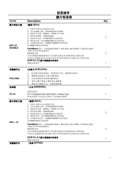
供货清单膜片钳系统Cat.No Description Qty 膜片钳放大器(德国HEKA)EPC-10 DOUBLE 1 双探头电脑全自动控制放大器。
2 具有Lockin功能,能精确测量膜电容测量。
3、钳制电压范围:±200mv,调幅最小为1mV4、钳制电流调整:±100nA/±2nA5、快速补偿电容:0-15pF(50G欧反馈电阻)5、慢补偿电容:0.2-1000pF(50G欧反馈电阻)6、全细胞反馈电容:1-255pF(1000M欧反馈电阻)3-1000pF(1M欧反馈电阻)1PatchMaster软件,多通道数据采集(8个A/D通道)与输出刺激(3个D/A输出通道)可输出多种多样的刺激波形P/N漏检功能具有全细胞和细胞贴附模式下进行膜电容测定的LOCK IN放大器的功能具有离子成像测定的扩展功能,扩展后可控制光源和对荧光测定进行控制的功能1IGOR Pro 5.0膜片钳数据分析软件数据分析软件 1显微操作仪(加拿大BURLEIGH)PCS-5400 1, 适合膜片钳实验操作,粗调部分手动,微调部分驱动;2,微操移动的最小步进为60纳米;3,压电晶体的形变范围300微米;4,带有与膜片钳放大器的探头适配器5,垂直水平旋转平台,方便更换电极1拉制器(日本NARISHIGE)PC-10 垂直拉制仪PC-10 Pipette Puller (220-240V): Vertical Type两步拉制仪,可以拉出尖端小于0.1um的电极1膜片钳放大器(德国HEKA)EPC-10 1 单探头电脑全自动控制放大器。
2 具有Lockin功能,能精确测量膜电容测量。
3、钳制电压范围:±200mv,调幅最小为1mV4、钳制电流调整:±100nA/±2nA5、快速补偿电容:0-15pF(50G欧反馈电阻)5、慢补偿电容:0.2-1000pF(50G欧反馈电阻)6、全细胞反馈电容:1-255pF(1000M欧反馈电阻)3-1000pF(1M欧反馈电阻)1PatchMaster软件,多通道数据采集(8个A/D通道)与输出刺激(3个D/A输出通道)可输出多种多样的刺激波形P/N漏检功能具有全细胞和细胞贴附模式下进行膜电容测定的LOCK IN放大器的功能具有离子成像测定的扩展功能,扩展后可控制光源和对荧光测定进行控制的功能1IGOR Pro 5.0膜片钳数据分析软件数据分析软件1显微操作仪(美国SUTTER)MP285 1 压电晶体技术驱动,精度60nm。
NBB10-30GM50-E2 接近开关
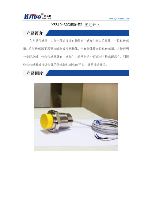
NBB10-30GM50-E2 接近开关
在各类传感器中,有一种对接近它物件有“感知”能力的元件——位移传感器。
这类传感器不需要接触到被检测物体,当有物体移向位移传感器,并接近到一定距离时,位移传感器就有“感知”,通常把这个距离叫“检出距离”。
利用位移传感器对接近物体的敏感特性制作的开关,就是接近开关。
产品图片 Photo 输出方式I / O mode 产品名称/型号
NBB10-30GM50-E2 接近开关
直流两线常开 直流两线常闭 直流三线NPN 常开 直流三线NPN 常闭 直流三线PNP 常开 直流三线PNP 常闭
交流两线常开 交流两线常闭
电气接线图 Connection diagram
规格参数 Specification
安装方式
埋入式/非埋入式;
插件式/引线式 测距 10;15;16;22;25;40(mm )
尺寸规格
M30
电源电压
10..36VDC
涟波<10%
空载电流<10mA
最大负载电流100mA 120mA
电压降<1.5V <6V
迟滞<15%(Sr)
开关频率800Hz 500Hz
防护等级IP67
过载保护电流150mA
感应面材质PTFE(特氟龙)
本文内容来源南京凯基特官网。
德国倍加福电容式传感器的使用说明
德国倍加福电容式传感器的使用说明
1.引言
2.传感器概述
3.传感器安装
3.1安装位置:传感器应安装在合适的位置,以确保能够正确检测到需要测量的物体。
3.2安装定位:传感器的安装位置应进行定位,并使用适当的固定装置进行固定,以避免因振动或其他原因导致误差。
4.传感器调试
4.1连接电源:将传感器连接到适当的电源,并确保电源稳定。
4.2连接信号线:将传感器的信号线连接到测量设备或控制系统,确保连接可靠。
4.3信号调整:根据实际应用需求,通过调整传感器的信号输出进行校准和调试。
5.传感器保养
5.1清洁:定期清洁传感器表面,以确保传感器的正常运行。
5.2防护:传感器应避免接触水和潮湿环境,以防止损坏。
5.3定期检查:定期检查传感器的连接线和固定装置是否松动,及时进行维修和更换。
6.故障排除
6.1无信号输出:检查传感器的电源连接和信号线连接是否正常,确保信号线没有断开或短路。
6.2误差过大:检查传感器的安装位置和固定是否正确,排除外部干扰因素。
7.安全注意事项
7.1使用前请阅读本使用说明书,并按照说明进行操作。
7.2请勿将传感器暴露在高温、高湿度或易爆环境中,以防损坏传感器。
7.3在维护、更换传感器时,请确保断开电源,并避免触摸到电器部件,以免发生触电事故。
8.其他信息
9.结束语
注:以上内容仅为示例,实际使用说明书中应结合具体产品的特点和使用要求进行编写。
英飞拓产品型号

英飞拓产品型号英飞拓产品型号渠道产品,价格优惠,不满意可退货 150********2.1 固定摄像机-PALV5101-A50142 ⼀体化摄像机2.3 因定半球摄像机2.4 V1700A系列快球2.5 V1750A系列充氮快球2.6 V1700S系列内置单模光端机的快球2.7 V1900A系列快球2.8⼀体化云台摄像机2.9恒速球形护罩/云台2.10快球零部件1.模拟监控前端产品2.1 固定摄像机V5101-A2014 V5101-A3014 V5101-A5014 V5101-A2019 V5101-A3019 V5102-A2014 V5102⽇夜型因定摄像机V5102-A3014 V5102-A5014V5102-A3019 V5102-A2019V5103宽动态彩⾊固定摄像机V5103-A3014V1025-1H⾼解析度彩⾊摄像机V1025-1HV1026-1⾼解析度⽇夜转换型摄像机V1026-1V1027-1 1/2英⼨宽动态⾼灵敏度低照度彩⾊摄像机V1027-1V1033-1宽动态⽇夜转换型摄像机V1033-12.2⼀体化摄像机PALV1224⼀体化彩⾊摄像机V1224-22A14V1244⼀体化⽇夜转换摄像机V1244-23A14 V1244-26A14 V5411-A2014ST V5411-A2014SU V5411-A2014SV 2.3固定半球摄像机PALV5411-A2014SW V5411-A2014SX V5411-A2014SYV5411-A2014SZ480线⼿动变焦⾃动光圈镜头V5411-A2014 SBV5411-A2014 SDV5411-A2014SE V5411-A2014SC V5411-A2014SF520线固定焦距镜头V5411-A3014ST V5411-A3014SU V5411-A3014SV V5411-A3014SW V5411-A3014SX V5411-A3014SY V5411-A3014SZ520线⼿动变焦⾃动光圈镜头V5411-A3014SB V5411-A3014SD V5411-A3014SE V5411-A3014SCV5512室内⽇夜型因定半球摄像机V5411-A3014SF V5512-A2014SB V5512-A2014SE520线⼿动变焦⾃动光圈镜头V5512-A3014SB V5512-A3014SEV5413室内宽动态彩⾊固定半球摄像机V5512-A3014SB V5413-A3024SB V5413-A3024SE2.3固定半球摄像机PALV5411-A2014ST V5411-A2014SU V5411-A2014SV V5411-A2014SW V5411-A2014SXV5411-A2014SY480线⼿动变焦⾃动光圈镜头V5411-A2014SZ V5411-A2014SB V5411-A2014SD V5411-A2014SE V5411-A2014SC V5411-A2014SF520线固定焦距镜头V5411-A3014ST V5411-A3014SU V5411-A3014SV V5411-A3014SW V5411-A3014SZ V5411-A3014SY V5411-A3014SX520线⼿动变焦⾃动光圈镜头V5411-A3014SB V5411-A3014SD V5411-A3014SE V5411-A3014SCV5512室内⽇夜型因定半球摄像机V5411-A3014SF V5512-A2014SB520线⼿动变焦⾃动光圈镜头V5512-A2014SE V5512-A3014SB V5512-A3014SB V5512-A3014SEV5413室内宽动态彩⾊固定半球摄像机V5413-A3024SBV1700A系列快球PAL室内吸顶装快球V1725A-C1C2C6 V1726A-C1C2C6 V1727A-C1C2C6 V1728A-C1C2C6 V1724A-C1C2C6 V1729A-C1C2C6 V1723A-C1C2C6室内⽀架装快球V1725A-C1C2B6 V1726A-C1C2B6 V1727A-C1C2B6 V1728A-C1C2B6 V1724A-C1C2B6 V1729A-C1C2B6 V1723A-C1C2B6室外吸顶装快球V1745A-C1C2C6 V1746A-C1C2C6 V1747A-C1C2C6 V1748A-C1C2C6 V1744A-C1C2C6 V1749A-C1C2C6 V1743A-C1C2C6室外⽀架装快球V1745A-C1C2B6 V1746A-C1C2B6 V1747A-C1C2B6 V1748A-C1C2B6 V1744A-C1C2B6 V1749A-C1C2B6 V1743A-C1C2B62.5 V1750A 系列充氮快球-PAL室内充氮吊装快球V1757A-C1C3B6 V1758A-C1C3B6 V1759A-C1C3B6 V1753A-C1C3B6 V1791室内内置单模光端机吸顶装快球V1725S-C1C2C6 V1726S-C1C2C6 V1727S-C1C2C6 V1728S-C1C2C6 V1729S-C1C2C6 V1723S-C1C2C6室内内置单模光端机⽀架装快球V1725S-C1C2B6V1726S-C1C2B6V1727S-C1C2B6 V1728S-C1C2B6 V1729S-C1C2B6 V1723S-C1C2B6室外内置单模光端机吸顶装快球V1745S-C1C2C6 V1746S-C1C2C6 V1747S-C1C2C6 V1748S-C1C2C6 V1743S-C1C2C6 V17243S-C1C2C6室外内置单模光端机⽀架装快球V1745S-C1C2B6 V1746S-C1C2B6 V1747S-C1C2B6 V1748S-C1C2B6 V1749S-C1C2B6 V1724S-C1C2B62.7V1900A系列快球PAL室内吸顶装快球V1901A-C1C2C6 V1902A-C1C2C6 V1903A-C1C2C6 V1904A-C1C2C6 V1906A-C1C2C6室内⽀架装快球V1901A-C1C2B6 V1902A-C1C2B6 V1903A-C1C2B6 V1904A-C1C2B6 V1906A-C1C2B6室外吸顶装快球V1911A-C1C2C6 V1912A-C1C2C6 V1913A-C1C2C6 V1914A-C1C2C6 V1916A-C1C2B6 V1917A-C1C2B6室外⽀架装快球V1911A-C1C2B6 V1912A-C1C2B6 V1913A-C1C2B6 V1914A-C1C2B6 V1916A-C1C2B6 V1917A-C1C2B62.8 ⼀体化云台摄像机V1492-18A15 V1492-23A15 V1492-26A15 V1492-35A15 V1492-36A15 V1492-18A16 V1492-23A16 V1492-26A16 V1492-35A16 V1492-36A16 V1492-18A17 V1492-23A17 V1492-26A17 V1492-35A17 V1492-36A17 V1492-18A18 V1492-23A18 V1492-26A18 V1492-35A18V1492-36A18⼀体化云台⽀架(适⽤于V1492、V1493)V1662-W1 V1662-S1 V1662-C1 V1662-DV1493中型⾼速云台V1493-D16V7A15 V1493-DP16V7A15 V1493-A15 V1493-D16V7A16 V1493-DP16V7A16 V1493-A16 V1493-D16V7A17 V1493-DP16V7A17 V1493-A17 V1493-D16V7A18 V1493-DP16V7A18 V1493-A18V1631隔爆云台摄像机V1631-23A19 V1631-25A19防爆护罩V1421-15SHB6-2V1421-15SHB8-2V1421-15A6-2V1421-15A8-2隔爆云台⽀架V1664-W V1664-C V1664-S V1665-W12.9恒速球形护罩/云台V1682 系列室内/室外恒速球形云台V1682-C2B-9HBPV1682-C2B-9HBP2.10 快球零部件V1761 V1761L V1762 V1763 V1764 V1764A V1764B V1765 V1765A V1766适⽤V1750A系列充氮快球V1761S V1762S V1763S球芯V1700N系列⽹络快球球芯(PAL)(坜另配视频缟码卡)V1825N-C16 V1826N-C16 V1827N-C16 V1828N-C16 V1829N-C16 V1825N-C15 V1826N-C15 V1827N-C15V1828N-C16 V1829N-C16V1700A系列快球球芯(PAL)V1825A-C16 V1826A-C16 V1827A-C16 V1828A-C16 V1829A-C16 V1825N-C15 V1826N-C15 V1827N-C15V1828N-C16 V1829N-C16V1750A系列充氮快球球芯(PAL)V1825AP-C16 V1826AP-C16 V1827AP-C16 V1828AP-C16 V1829AP-C16 V1825AP-C15 V1826AP-C15 V1827AP-C15 V1828AP-C15 V1829AP-C15V1700S系列光端机快球球芯(PAL)V1825AF-C16 V1826 AF-C16 V1827 AF-C16 V1828 AF-C16 V1829 AF-C16 V1825AF-C15 V1826 AF-C15 V1827 AF-C15 V1828 AF-C15 V1829 AF-C15V1900A系列快球球芯(PAL)V1901A-C16 V1902A-C16 V1903A-C16 V1904A-C16 V1905A-C16 球罩快球下罩(不带法兰)V1840-C2 V1840-S2 V1840-C3 V1840-S3室内吸顶装配罩下罩(带法兰)V1840-C2C V1840-S2C V1840-C3C V1840-S3C室内⽀架装配罩下罩(带法兰)V1840-C2B V1840-S2B V1840-C3B V1840-S3B室外⽀架装和吸顶装配罩下罩(带法兰和加热器)V1840-C2O V1840-S2O V1840-C3O V1840-S3O V1840P-C3OV1840P-S3O快球上罩(带法兰)V1850-IC V1850-IB V1850-OC V1850-OB V1850P-OB V1852-IC V1852-IB V1852-OC V1852-OB快球电源板V1860A-C6 V1860N-L6 V1860A-C5 V1860N-L5快球电源V3922-24A-26.键盘及辅助设备6.1 键盘V2100 V2109X V2111X V2110 V2115 V2116X7.3 V2020系列中型矩阵切换/控制器V2020AX-16X4 V2020AX-16X8 V2020AX-16X12 -16X16 V2020AX-16X20 V2020AX-16X24 V2020AX-16X28V2020AX-16X32 V2020AX-32X4 V2020AX-32X8 V2020AX-32X12 V2020AX-32X16 V2020AX-32X20 V2020AX-32X24 V2020AX-32X28 V2020AX-32X32 V2020AX-48X4 V2020AX-48X8V2020AX-48X12 V2020AX-48X16 V2020AX-48X20 V2020AX-48X24 V2020AX-48X28 V2020AX-48X32 V2020AX-64X4 V2020AX-64X8 V2020AX-64X12 V2020AX-64X16 V2020AX-64X20 V2020AX-64X24 V2020AX-64X28 V2020AX-64X32 V2020AX-80X4 V2020AX-80X8 V2020AX-80X12 V2020AX-80X16 V2020AX-80X20 V2020AX-80X24V2020AX-80X28 V2020AX-80X32 V2020AX-96X4 V2020AX-96X8 V2020AX-96X12 V2020AX-96X16 V2020AX-96X20 V2020AX-96X24 V2020AX-96X28 V2020AX-96X32V2020AX-112X4 V2020AX-112X8 V2020AX-112X12 V2020AX-112X16 V2020AX-112X20 V2020AX-112X24V2020AX-112X28 V2020AX-112X32 V2020AX-128X4 V2020AX-128X8 V2020AX-128X12 V2020AX-128X16V2020AX-128X20 V2020AX-128X24 V2020AX-128X28 V2020AX-128X32 V2020AX-144X4 V2020AX-144X8V2020AX-144X12 V2020AX-144X16 V2020AX-144X20 V2020AX-144X24 V2020AX-144X28 V2020AX-144X32V2020AX-160X4 V2020AX-160X8 V2020AX-160X12 V2020AX-160X16 V2020AX-160X20 V2020AX-160X24V2020AX-160X28 V2020AX-160X32 V2020AX-176X4 V2020AX-176X8 V2020AX-176X12 V2020AX-176X16V2020AX-176X20 V2020AX-176X24 V2020AX-176X28 V2020AX-176X32 V2020AX-192X4 V2020AX-192X8V2020AX-192X12 V2020AX-192X16 V2020AX-192X20 V2020AX-192X24 V2020AX-192X28 V2020AX-192X32 V2020AX-208X4 V2020AX-208X8 V2020AX-208X12 V2020AX-208X16 V2020AX-208X20 V2020AX-208X24V2020AX-208X28 V2020AX-208X32 V2020AX-224X4 V2020AX-224X8 V2020AX-224X12 V2020AX-224X16V2020AX-224X20 V2020AX-224X24 V2020AX-224X28 V2020AX-224X32 V2020AX-240X4 V2020AX-240X8 V2020AX-240X12 V2020AX-240X16 V2020AX-240X20 V2020AX-240X24 V2020AX-240X28 V2020AX-240X32V2040AX-16X4 V2040AX-16X8 V2040AX-16X12 V2040AX-16X16 V2040AX-16X20 V2040AX-16X24V2040AX-16X28 V2040AX-16X32 V2040AX-32X4 V2040AX-32X8 V2040AX-32X12 V2040AX-32X16V2040AX-32X20 V2040AX-32X24 V2040AX-32X28 V2040AX-32X32 V2040AX-48X4 V2040AX-48X8V2040AX-48X12 V2040AX-48X16 V2040AX-48X20 V2040AX-48X24 V2040AX-48X28 V2040AX-48X32V2040AX-64X4 V2040AX-64X8 V2040AX-64X12 V2040AX-64X16 V2040AX-64X20 V2040AX-64X24 V2040AX-64X28 V2040AX-64X32 V2040AX-80X4 V2040AX-80X8 V2040AX-80X12 V2040AX-80X16 V2040AX-80X20V2040AX-80X24 V2040AX-80X28 V2040AX-80X32V2040AX-96X4 V2040AX-96X8 V2040AX-96X12 V2040AX-96X16 V2040AX-96X20 V2040AX-96X24 V2040AX-96X28 V2040AX-96X32 V2040AX-112X4 V2040AX-112X8 V2040AX-112X12 V2040AX-112X16 V2040AX-112X20 V2040AX-112X24 V2040AX-112X28V2040AX-112X32 V2040AX-128X4 V2040AX-128X8 V2040AX-128X12 V2040AX-128X16V2040AX-128X20 V2040AX-128X24 V2040AX-128X28 V2040AX-128X32 V2040AX-144X4V2040AX-144X8 V2040AX-144X12 V2040AX-144X16 V2040AX-144X20 V2040AX-144X24V2040AX-144X28 V2040AX-144X32 V2040AX-160X4 V2040AX-160X8 V2040AX-160X12V2040AX-160X16 V2040AX-160X20 V2040AX-160X24 V2040AX-160X28 V2040AX-160X32 V2040AX-176X4V2040AX-176X8 V2040AX-176X12 V2040AX-176X16 V2040AX-176X20V2040AX-176X24 V2040AX-176X28 V2040AX-176X32 V2040AX-192X4 V2040AX-192X8V2040AX-192X12 V2040AX-192X16 V2040AX-192X20 V2040AX-192X24 V2040AX-192X28V2040AX-192X32V2040AX-208X4 V2040AX-208X8 V2040AX-208X12 V2040AX-208X16 V2040AX-208X20 V2040AX-208X24V2040AX-208X28 V2040AX-208X32 V2040AX-224X4 V2040AX-224X8 V2040AX-224X12 V2040AX-224X16V2040AX-224X20 V2040AX-224X24 V2040AX-224X28 V2040AX-224X32 V2040AX-240X4 V2040AX-240X8V2040AX-240X12 V2040AX-240X16 V2040AX-240X20 V2040AX-240X24 V2040AX-240X28 V2040AX-240X32V2040AX-256X4V2040AX-256X8 V2040AX-256X12 V2040AX-256X16 V2040AX-256X20 V2040AX-256X24V2040AX-256X28 V2040AX-256X32A2011X-16X5 A2011X-32X5 A2020X-16X4 A2020X-16X8 A2020X-16X12 A2020X-16X16 A2020X-16X20 A2020X-16X24 A2020X-16X28 A2020X-16X32 A2020X-32X4 A2020X-32X8 A2020X-32X12 A2020X-32X16 A2020X-32X20 A2020X-32X24 A2020X-32X28A2020X-32X32 A2020X-48X4 A2020X-48X8 A2020X-48X12 A2020X-48X16 A2020X-48X20A2020X-48X24 A2020X-48X28 A2020X-48X32 A2020X-64X4 A2020X-64X8 A2020X-64X12A2020X-64X16 A2020X-64X20 A2020X-64X24 A2020X-64X28 A2020X-64X32 A2020X-80X4A2020X-80X8 A2020X-80X12 A2020X-80X16 A2020X-80X20 A2020X-80X24 A2020X-80X28A2020X-80X32 A2020X-96X4 A2020X-96X8 A2020X-96X12 A2020X-96X16 A2020X-96X20 A2020X-96X24 A2020X-96X28 A2020X-96X32 A2020X-112X4A2020X-112X8 A2020X-112X12 A2020X-112X16 A2020X-112X20 A2020X-112X24A2020X-112X28 A2020X-112X32 A2020X-128X4 A2020X-128X8 A2020X-128X12 A2020X-128X16 A2020X-128X20 A2020X-128X24 A2020X-128X28 A2020X-128X32A2020X-144X4 A2020X-144X8 A2020X-144X12 A2020X-144X16 A2020X-144X20 A2020X-144X24 A2020X-144X28 A2020X-144X32 A2020X-160X4 A2020X-160X8 A2020X-160X12 A2020X-160X16 A2020X-160X20 A2020X-160X24 A2020X-160X28A2020X-160X32 A2020X-176X4 A2020X-176X8 A2020X-176X12 A2020X-176X16 A2020X-176X20A2020X-176X24 A2020X-176X28 A2020X-176X32 A2020X-192X4 A2020X-192X8 A2020X-192X12 A2020X-192X16 A2020X-192X20 A2020X-192X24 A2020X-192X28 A2020X-192X32 A2020X-208X4 A2020X-208X8。
米科-LDG LDGC-SUP电磁流量计 使用说明书
User's Manual杭州米科传感技术有限公司更多资讯请扫二维码服务电话:400-163-1718杭州米科传感技术有限公司电磁流量计使用说明书U-MIK-LDG/LDGC-SUP-CN9第9版前言●感谢您购买本公司产品。
●本手册是关于产品的各项功能、接线方法、设置方法、操作方法、故障处理方法等的说明书。
●在操作之前请仔细阅读本手册,正确使用本产品,避免由于错误操作造成不必要的损失。
●在您阅读完后,请妥善保管在便于随时取阅的地方,以便操作时参照。
注意●本手册内容如因功能升级等有修改时,恕不通知。
●本手册内容我们力求正确无误,如果您发现有误,请与我们联系。
●本手册内容严禁转载、复制。
●本产品禁止使用在防爆场合。
版本U-MIK-LDG/LDGC-SUP-CN9第九版2022年4月确认包装内容打开包装箱后,开始操作之前请先确认包装内容。
如发现型号和数量有误或者外观上有物理损坏时,请与本公司联系。
产品清单产品包装内容温馨提醒:若使用脉冲输出信号,建议接线时使用上拉电阻。
对应端子为POUT、PCOMPOUT为脉冲信号、PCOM为信号地注:左侧端子为冷热量计端子接线原理图:建议:图中上拉电阻R建议使用2K,0.5W的电阻,另外电源E建议使用24V直流电。
目录第一章产品概述 (1)1.1热量表工作原理 (1)1.2电磁流量计测量原理 (2)1.3电磁流量计结构 (3)1.4仪器说明 (4)1.5接线端子说明 (4)第二章安全指导 (7)2.1生产厂家的安全指导 (7)2.2对操作者的安全指导 (9)2.3售后服务 (9)第三章安装 (10)3.1安装提示 (10)3.2存放 (10)3.3安装要求 (10)3.4管路设计 (10)3.5传感器安装工艺 (12)3.6热量表安装要求 (15)3.7机械安装 (17)3.8管道式电磁流量计的传感器尺寸 (20)3.9转换器尺寸 (21)第四章电气连接 (22)4.1安全提示 (22)4.2连接信号电缆 (22)4.3测量传感器接地 (23)4.4转换器电源连接 (24)4.5输入说明 (26)4.6输出说明 (27)第五章启动 (29)5.1开启电源 (29)5.2转换器启动 (29)第六章操作 (30)6.1热量显示画面 (30)6.2流量显示界面 (31)6.3红外按键操作说明 (32)6.4机械按键操作说明 (32)6.5快速设置菜单 (33)6.6流量组态详细说明 (34)6.7热量组态详细说明 (41)6.8操作说明 (43)第七章功能 (49)7.1系统信息 (49)7.2报表操作说明 (50)7.3脉冲/频率/电流输出 (54)7.4串口通信 (55)7.5Hart通信 (57)第八章技术参数 (65)8.1技术参数 (65)8.2电磁流量计电极材料的选择 (68)8.3电磁流量计流量流速对照表 (69)8.4精度 (70)第九章插入式电磁流量计系列 (71)9.1产品的功能用途和适用范围 (71)9.2产品的形式和组成 (72)9.3主要技术性能 (72)9.4结构 (73)9.5安装和使用 (74)9.6维护、修理和常见故障排除 (77)第一章产品概述第一章产品概述1.1热量表工作原理热量表的工作原理:由热源供应的热水(冷水)以较高(低)的温度流入热交换系统(散热器、换热器或由它们组成的复杂系统),以较低(高)的温度流出,在此过程中,通过热量交换向用户释放或吸收热量(注:该过程包括采暖系统和制冷系统能量交换过程)。
FH41系列高速传输连接器的特点说明书

■Materials
Part Insulator
Contacts Metal fittings
Material LCP
Phosphor bronze Brass
Finish Color:Gray Color:Black Gold plated
Pure tin reflow plated
Remarks UL94V-0
20 cycles
5.Vibration
No electrical discontinuity of 1µs or longer Contact resistance: 100 mø max. No damage, cracks, or parts dislocation
Frequency: 10 to 55 Hz, single amplitude of 0.75mm, 10 cycles in each of the 3 directions
Note 1. When passing the current through all of the contacts, use 70% of the rated current. Note 2. Includes temperature rise caused by current flow. Note 3. The term "storage" refers to products stored for a long period prior to mounting and use.
7.Humidity (Steady state)
Contact resistance: 100 mø max. Insulation resistance: 50 Mø min. No damage, cracks, or parts dislocation
锐德超声MX2辅助诊断仪器租赁说明书

920-218B-ENThe Standard in Phased Array, Redefined•Bright, Large-Size Screen •Fast, Intuitive Touch-ScreenInterface •Advanced Weld Overlay •High-Capacity Data Storage •Fast File Transfer•NEW OmniPC Analysis SoftwareAdvanced Test Equipment Rentals 800-404-ATEC (2832)®E s t a b l i s h e d 1981The Standard in Phased Array, RedefinedThe result of over 10 years of proven leadership inmodular NDT test platforms, the OmniScan MXhas been the most successful portable and modularphased array test instrument produced by Olympusto date, with thousands of units in use throughoutthe world.Building on a Solid BasisThis second generation OmniScan MX2 increasestesting efficiencies, ensuring superior manual andadvanced AUT application performance with fastersetups, test cycles, and reporting, in addition to uni-versal compatibility with all phased array and ultra-sound modules: past, present and future. Designedfor NDT leaders, this high-end, scalable platformdelivers true next-generation NDT performance.The OmniScan MX2 offers a high acquisition rateand new powerful software features for efficientmanual and automated inspection performance—all in a portable, modular instrument.Faster Is Better!Powerstart your day the right way with theOmniScan MX2. The OmniScan MX2 simplifiesand speeds up the setup process with its new WeldOverlay software feature, so you can start testingimmediately. Featuring the industry-standard phasedarray user interface with faster-than-ever perfor-mance, a bigger and brighter 10.4 in. screen, newand unique intuitive touch-screen capabilities, andfaster data transfer, enabling you to get to your nextinspection quicker.More Rugged than EverThe OmniScan MX2 is now designed for IP66, andbuilt to withstand the drops, spills, and abuse thattypically occur in the most demanding inspectionenvironments.More than an Instrument—A Solution ProviderThe OmniScan MX2 is an important part of yourinspection solution, and can be combined withother critical components to form a completeinspection system. Olympus offers a completeproduct range that includes phased array probes,scanners, analysis software, and accessories, allof which are integrated and packaged into rapidlydeployable, application-specific solutions for quickreturns on your investment. In addition, Olympusoffers a high-quality calibration and repair serviceworldwide, which is backed by a team of phasedarray application experts to ensure that you get thesupport you need.Life-Size OmniScan MX23Touch-Screen InterfaceThe revolutionary touch-screen interface offers simple and quick navigation, enhancedtext input functions, and easier, faster cursor control and gate setup.Full-Screen ModeThe unique full-screen mode offers operators increased viewing comfort, in addition to better readability at a distance.This feature can be used in both acquisition and analysis mode.Weld Overlay WizardThe Weld Overlay Wizard facilitates the creation of industry-standard weld over-lays for analysis assistance and volumetric flaw placement.OmniScan MXOmniScan MX2100% brighter screen4Modular InstrumentBackward Compatible. Forward Compatible.An Evolving Platform for your Growing Needs.Designed to secure both your current and future phased array invest-ments, the OmniScan MX2 can house any Olympus phased array module, including the reliable, field-proven models currently available, and the next-generation modules of the future. Its open architecture also supports future software updates and phased array module upgrades with configurations from 16:64M to 32:128 to ensure that your instrument evolves with your testing needs, and that you get the most from your investment.Module Compatibility OmniScan MX2OmniScan MX OMNI-M-PA1664M✔✔OMNI-M-PA1664✔OMNI-M-PA16128✔✔OMNI-M-PA32128✔✔OMNI-M-PA32128PR✔✔OMNI-M-PA3232 (200 V)✔✔OMNI-M-UT✔✔OMNI-M-ECT/ECA✔Software CompatibilityMXU-3.X1✔MXU-2.X setup and data files✔✔TomoView 2.9R12 (or higher)1✔✔TomoView Remote Control✔✔1. Data file compatibilityUT2 UT4 UT816:64 PA M16:64 PA16:128 PA32:32 PA32:128 PA5 Zooming and PanningGate Selection and MovementCursor Selection and MovementThe touch screen’s zooming functions can be used to zoom in on a specific area.In Zoom mode, swipe to pan the window contents.eters.In Cursor mode, tap once on a cursor to select it. Double-tap on a posi-tion to move the cursor to the desired location.In Gate mode, tap and hold a gate to move it to a new position.Text and Value InputDouble-tap on a parameter to bring up the keyboards or keypad on which values can beentered. Alphabetic and a numeric keyboards are available.67SetupGroup Wizard for All Essential Parameters• Material selection, with a database for shear and longitudinal velocities, and configuration of components for flat or curved surfaces.• A group copy option in the Wizard for fast creation of symmetrical two-probe inspections.• Wedge selection from a database of Olympus wedges.• Auto probe detection.• Scanner configuration with offsets, skews, and probe positions.• Wizard guidance for phased array, conventional UT, and TOFD channels.• Detailed interactive and illustrated help menu for every step in the Wizard.• Weld Overlay and RayTracing: step-by-step Wizard to configure the weld geometry.Setup SpeedOmniScan MX OmniScan MX250% fasterS-Scan and A-Scan Display Refresh RateOmniScan MX OmniScan MX2300% betterCalibrationCode-Compliant CalibrationThe Calibration Wizards ensure that every focal law in every group is the direct equivalent of a single-channel conventional flaw detector.Calibration Wizards• Guide the user step-by-step through Velocity, Wedge Delay, Sensitivity, TCG, DAC, AWS, and DGS calibrations.• Enable experimental or theoretical sensitivity, and TCG curves based on two, three, or all beams for a real or interpolated calibration.• Offer a simple, easy-to-use interface that enables all focal laws to be visualized simultaneously for a particular calibration task.• Features an interactive help menu with detailed graphics and definitions, which is available in each step of each Wizard.Scan plan adjustment using the Focal Law Wizard.Sensitivity calibration for a defined section in a sectorial scan.Sensitivity calibration for all beams in a sectorial scan.UT parameter adjustment using the touch-screen software keypad.8Acquisition• A scan menu for quick and easy configuration of inspection parameters for manual, one-line, raster, and helicoidal scans.• Multiple encoder modes, including Clock, Quadrature, and Clicker.• C-scan configuration for amplitude and position C-scans, and display setup.• Data storage options for full A-scans, S-scans, and/or C-scans.• Preconfigured display layouts for easy inspection preparation.• PRF auto adjustments for optimized, maximum speed, or manually-controlled settings.• Data storage options for flash card or USB media devices.• Real-time data acquisition displays, with the ability to rewrite data in both scan directions when using an encoder.• Easy to interface with encoded scanners.• Different gate-synchronization capabilities.Pulse Repetition Frequency (PRF)OmniScan MX OmniScan MX240% betterSaving Inspection Data File to USB (speed)OmniScan MX OmniScan MX2Up to 400% betterMaximum File Size (Mb)OmniScan MX 160 MbOmniScan MX2300 MbFlawless Data ManagementAn SD Card is used to store data for easy transfer to a computer. The SD card can also be inserted and removed without having to reboot the unit. In addition, data can be transferred to exter-nal media using the USB 2.0 port. The OmniScan MX2 provides data transfer speeds up to 400% faster than the OmniScan MX (depending on the device used).Analysis• An extensive display menu for preconfigured multigroup and multiprobe inspection layouts.• Data, reference, and measurement cursors for defect sizing and reporting.• Extensive Readings database for trigonometry, flaw statistics on axes, volumetric position information, code-based acceptance criteria, corrosion mapping statistics, etc.• All Readings are available online, and are also available off-line when full A-scans are saved in data files.• Linked displays for interactive analysis of A-scans, B-scans, S-scans, and C-scans for multigroup and multiprobe inspections.• Optimized preconfigured layouts for quick and simple length, depth, and height sizing of flaws for code-based or non-code-based inspections.• Interactive off-line gate repositioning.Top: Data acquisition displaying TOFD. Right: Data acquisition displaying two phased array channels andTOFD.Weld inspection display showing the position of indications in the RayTracing display.This new software is the most efficient and affordable option for OmniScan data analysis,and features the same analysis tools provided in the OmniScan onboard software, with theOptimized use of your OmniScan: The OmniScan unit can now be used strictly forscanning while analysis is performed simultaneously on a personal computer.Same user interface as the OmniScan. An inspector with training on the OmniScan isCompatible with extra large screens for increased visibility during analysis.Intuitive keyboard shortcuts have been added to boost productivity levels9TomoView offers advanced post-processing of OmniScan Dual matrix PA probe (TRL).Indication table built from composite inspection data.11Typical ApplicationsGirth Weld InspectionThe OmniScan PA is at the heart of the Olympus manual andsemiautomated circumferential weld-inspection solutions developed for the oil and gas industry. These phased array systems, which are certified for tube inspection in compliance with ASME, API, and other code criteria, offer superior inspection speed and detection, andfacilitate interpretation of indications.Pressure Vessel Weld InspectionA complete inspection of pressure vessel welds can be performed in a single scan using an OmniScan PA and a motorized scanner such as the WeldROVER. By combining TOFD and PA in a single inspection pass, a significant reduction in inspection time can be achieved as compared with conventional raster scanning or radiography. Further-more, inspection results are available immediately, enabling you todetect problems with welding equipment and fix them right away.Weld Inspection of Small-Diameter PipesWhen coupled with the COBRA manual scanner, the OmniScan flaw detector is capable of inspecting pipes ranging from 0.84 in. OD to 4.5 in. OD. With its very slim design, this manual scanner is able to inspect pipes in areas with limited access. Adjacent obstructions such as piping, supports, and structures can be as close as 12 mm (0.5 in.).Manual and Semiautomated Corrosion MappingThe OmniScan PA sytem with the HydroFORM scanner is designed to offer the best inspection solution for detecting wall-thickness reduc-tions resulting from corrosion, abrasion, and erosion. In addition, it detects mid-wall damage such as hydrogen-induced blistering and manufacturing-induced laminations, and easily differentiates these anomalies from loss of wall thickness.For this application, phased array ultrasound technology offers supe-rior inspection speed, data point density, and detection.Composite InspectionParts made of laminate composite materials pose an inspection chal-lenge due to their various shapes and thicknesses.Olympus offers complete solutions for the inspection of carbon-fiber-reinforced polymer structures. These solutions are based on the OmniScan flaw detector, the GLIDER ™ scanner, and dedicated probesand wedges designed for CFRP flat panel and radius inspection.48 Woerd Avenue, Waltham, MA 02453, USA, Tel.: (1) 781-419-390012569 Gulf Freeway, Houston, TX 77034, USA, Tel.: (1) 281-922-9300505, boul. du Parc-Technologique, Québec (Québec) G1P 4S9, Tel.: (1) 418-872-11551109 78 Ave, Edmonton (Alberta) T6P 1L8*******************OmniScan_MX2_EN_201203 • Printed in Canada • Copyright © 2012 by Olympus NDT.*All specifications are subject to change without notice.All brands are trademarks or registered trademarks of their respective owners and third party entities.is ISO 9001 and 14001 certified.Compatible with the Following Inspection Codes:The OmniScan MX2 is compatible with standard industry inspection codes, including, but not limited to:ASME Section V , Article 4AWSAll ASME phased array code cases API 1104 and API RP2X ASTM E2700-09CEN EN 583-6ASTM E2491-06BSI BS7706… and moreOmniScan MX2 Specifications。
帕帕尔+富斯 KFD0-CS-Ex2.51P 区域2分类2区域0、1、2分类1、2传感器安全电子产品

R e l e a s e d a t e 2017-08-09 14:20D a t e o f i s s u e 2017-08-09072149_e n g .x m lZone 2Div. 22-1+11+12-9+10-8-5-4+ConnectionAssembly•2-channel isolated barrier•24 V DC supply (loop powered)•Current input/output 0 mA ... 40 mA •I/P or transmitter power supply •Accuracy 1 %•Up to SIL 2 acc.to IEC 61508FunctionThis isolated barrier is used for intrinsic safety applications.The device transfers DC signals of fire alarms and smoke alarms from the hazardous area to the non-hazardous area. The device can also be used to control I/P converters, valves, indicators, and audible alarms.A reverse polarity protection prevents damage to the device caused by faulty wiring.The device is loop powered. From the control side no additional power supply has to be connected.Use the technical data to verify that proper voltage is available to the field devices.2FeaturesFront viewR e l e a s e d a t e 2017-08-09 14:20D a t e o f i s s u e 2017-08-09072149_e n g .x mlGeneral specifications Signal typeAnalog input/analog output Functional safety related parameters Safety Integrity Level (SIL) SIL 2Supply Rated voltage U rloop poweredControl circuit Connection terminals 12-, 11+; 8-, 10-, 9+Voltage 4 ... 35 V DC Current0 ... 40 mAPower dissipation at 40 mA and U in < 22 V: 700 mW per channel at 40 mA and U in > 22 V: 1.2 W per channel Field circuit Connection terminals 1+, 2-; 4+, 5-Voltagefor 4 V < U in < 24 V: ≥ U in - (0.37 x current in mA) - 1.0 for U in > 24 V: ≥ 21 V - (0.36 x current in mA)Short-circuit current at U in > 24 V: ≤ 65 mA Transfer current≤ 40 mATransfer characteristicsAccuracy 1 %DeviationAfter calibration≤ ± 200 µA; incl. calibration, linearity, hysteresis and load fluctuations at the field side up to a load of 1 k Ω and current ≤ 20 mA at 20 °C (68 °F)Influence of ambient temperature ≤ ± 2 µA/K at U in ≤ 20 V; ≤ ± 5 µA/K at U in > 20 V Rise time≤ 5 ms at bounce from 4 ... 20 mA and U in < 24 VGalvanic isolation Field circuit/control circuit safe electrical isolation acc. to IEC/EN 60079-11, voltage peak value 375 V Indicators/settings Labelingspace for labeling at the front Directive conformity Electromagnetic compatibilityDirective 2014/30/EU EN 61326-1:2013 (industrial locations)ConformityElectromagnetic compatibility NE 21:2006Degree of protectionIEC 60529:2001Protection against electrical shock UL 61010-1Ambient conditions Ambient temperature -20 ... 60 °C (-4 ... 140 °F)Mechanical specifications Degree of protection IP20Connection screw terminalsMass approx. 100 gDimensions 20 x 107 x 115 mm (0.8 x 4.2 x 4.5 inch) , housing type B1Mountingon 35 mm DIN mounting rail acc. to EN 60715:2001Data for application in connection with hazardous areasEU-Type Examination CertificateBAS 98 ATEX 7343Marking¬ II (1)G [Ex ia Ga] IIC, II (1)D [Ex ia Da] IIIC, I (M1) [Ex ia Ma] I (-20 °C ≤ T amb ≤ 60 °C)Voltage U o 25.2 V Current I o 93 mA Power P o 585 mW Control circuit Maximum safe voltageU m 250 V eff (Attention! The rated voltage can be lower.)Field circuitMaximum safe voltage U m250 V eff (Attention! The rated voltage can be lower.)Certificate TÜV 99 ATEX 1499 XMarking ¬ II 3G Ex nA II T4 [device in zone 2]Galvanic isolationField circuit/control circuit safe electrical isolation acc. to IEC/EN 60079-11, voltage peak value 375 V Directive conformityDirective 2014/34/EU EN 60079-0:2012+A11:2013 , EN 60079-11:2012 , EN 60079-15:2010International approvals FM approval Control drawing 116-0129UL approval17-08-09 14:20D a t e o f i s s u e 2017-08-09072149_e n g .x mlControl drawing 116-0173 (cULus)IECEx approval IECEx BAS 05.0004Approved for [Ex ia Ga] IIC, [Ex ia Da] IIIC, [Ex ia Ma] IGeneral information Supplementary informationObserve the certificates, declarations of conformity, instruction manuals, and manuals where applicable. For information see .17-08-09 14:20D a t e o f i s s u e 2017-08-09072149_e n g .x mlThe device is used for isolation of power loops for the control of positioner, I/P converters etc. A current source is connected to the safe area terminals.The device is used for isolation of a current signal from fire detectors or similar sensors. In this case, a voltage source can be connected to the safe area terminals. A specific measurement current across a passive sensor can be measured in the safe area with a series resistor (min.50Ω). When a voltage supply is used, the measuring resistor can also provide current limitations.Application。
倍加福旋转编码器型安全操作及保养规程
倍加福旋转编码器型安全操作及保养规程在工业领域中,高质量的传感器与编码器往往起着关键作用,而旋转编码器则是传感器中的一种,它主要由内部的感应器、电子设备、转子等部分组成,实现了对旋转轴的位置和速度实时监测。
倍加福旋转编码器型是市场上颇受欢迎的一种,它具有精度高、灵敏度好、可靠性高等特点,适用于多种不同的工作场合。
本文将介绍倍加福旋转编码器型的安全操作与保养规程,以确保设备的正常运转和延长使用寿命。
安全操作规程1. 固定设备在使用倍加福旋转编码器型时,首先需要把设备固定在支架上,以避免设备松动或受到外部冲击而影响测量精度。
在固定设备时,应注意以下几点:•支架的稳定性:支架必须牢固,能够承受设备的重量和运动产生的惯性力,支架所放置的表面也必须牢靠。
•安装高度的确定:根据实际需求和设备精度,确定测量点的高度和旋转角度,避免短时间内发生超量程的情况。
•安装位置的合理性:设备应安装在转动平滑、无振动干扰和较为静止的工作台面上,避免受到外部干扰而产生测量误差。
2. 电气接口在安装设备时,确保正确连接电气接口非常重要。
安装前需要认真查阅设备的接口说明书,以了解设备的各项参数,并确认设备的电气接口是否与导线接口相匹配。
在连接电气接口时,应注意以下事项:•接口匹配:检查设备的电气参数表,确保导线与设备的电气接口匹配,以提高信号传输的准确度。
•接口方向:根据设备说明书,仔细安装电气接口并查看配线的接口方向是否正确,避免连接错误或者断开。
•接线安全:连接时使用合适的工具,确保引脚连接良好,电气接口连接紧固无松动。
同时,也要注意保持导线的整洁有序,避免绕在一起导致松动或接触紊乱。
3. 正确校准设备设备在运行前需要进行校准,以确保其准确性能和稳定性。
在进行设备的校准时,应注意以下几点:•如何校准:按照设备的校准说明书进行,同时校准时必须由专业人员或者有经验的工程师进行。
•校准时间:分别在新设备启动、设备在使用过程中发生错误时以及定期(每年一次)进行检查来确定设备的准确性。
