WPR 08_078_04
DMG80480F070_01WTR产品数据手册说明书

DMG80480F070_01WTR产品概述:●基于T5L0芯片,运行DGUS II系统。
●7寸,800*480分辨率,262K色,TN屏,普通视角。
●液晶屏与触摸屏框贴工艺,产品厚度仅5.1mm。
●COF结构,将智能屏的整个核心电路固定于液晶模组FPC上,适合结构要求轻、薄,成本要求苛刻,生产简单的应用。
●排线共50个pin脚,引出用户CPU核的IO、UART、CAN、AD、PWM等接口,二次开发十分方便。
Features:●Based on T5L0,running DGUS II system.●7inch,800*480pixels resolution,262K colors,TN-TFT-LCD,normal viewing angel.●LCD and TP frame lamination process,only5.1mm thickness.●COF structure.The entire core circuit of the smart screen is fixed on the FPC of LCM,featured by lightand thin structure,low cost and easy production.●50pins,including IO,UART,CAN,AD and PWM from user CPU core for easy secondary development.1外部接口External InterfacePIN 序号Definition 定义I/O Functional Description 功能描述1+5V I 供电输入,DC3.6-5.5V 。
Power supply,DC3.6-5.5V.2+5V I 3GND GND GND4GND GND 5GND GND 6AD7I 5路ADC 输入,3.3V 电源做为参考,12bit 分辨率,输入电压范围0-3.3V 。
第三方路由器固件支持的路由列表
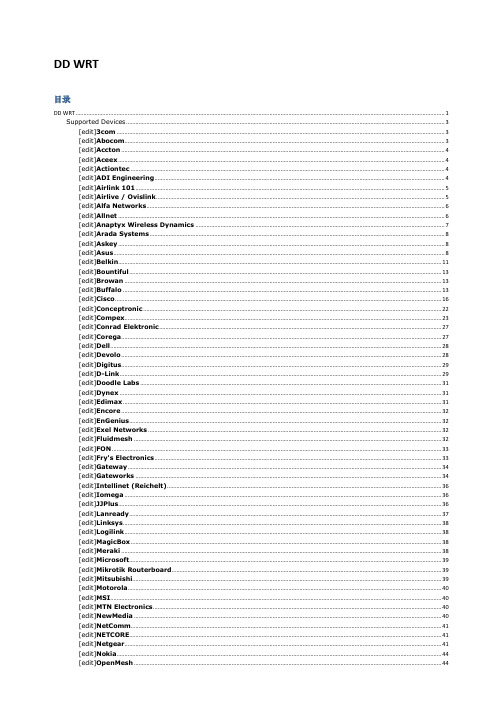
DD WRT目录DD WRT (1)Supported Devices (3)[edit]3com (3)[edit]Abocom (3)[edit]Accton (4)[edit]Aceex (4)[edit]Actiontec (4)[edit]ADI Engineering (4)[edit]Airlink 101 (5)[edit]Airlive / Ovislink (5)[edit]Alfa Networks (6)[edit]Allnet (6)[edit]Anaptyx Wireless Dynamics (7)[edit]Arada Systems (8)[edit]Askey (8)[edit]Asus (8)[edit]Belkin (11)[edit]Bountiful (13)[edit]Browan (13)[edit]Buffalo (13)[edit]Cisco (16)[edit]Conceptronic (22)[edit]Compex (23)[edit]Conrad Elektronic (27)[edit]Corega (27)[edit]Dell (28)[edit]Devolo (28)[edit]Digitus (29)[edit]D-Link (29)[edit]Doodle Labs (31)[edit]Dynex (31)[edit]Edimax (31)[edit]Encore (32)[edit]EnGenius (32)[edit]Exel Networks (32)[edit]Fluidmesh (32)[edit]FON (33)[edit]Fry's Electronics (33)[edit]Gateway (34)[edit]Gateworks (34)[edit]Intellinet (Reichelt) (36)[edit]Iomega (36)[edit]JJPlus (36)[edit]Lanready (37)[edit]Linksys (38)[edit]Logilink (38)[edit]MagicBox (38)[edit]Meraki (38)[edit]Microsoft (39)[edit]Mikrotik Routerboard (39)[edit]Mitsubishi (39)[edit]Motorola (40)[edit]MSI (40)[edit]MTN Electronics (40)[edit]NewMedia (40)[edit]NetComm (41)[edit]NETCORE (41)[edit]PC-Engines (46)[edit]Planex aka PCi (46)[edit]Ravo (46)[edit]RayTalk (46)[edit]Repotec (47)[edit]RFNet Technologies (47)[edit]Rosewill (47)[edit]Senao / EnGenius (48)[edit]Siemens (50)[edit]Sitecom (51)[edit]Snapgear (52)[edit]SOEKRIS Engineering (52)[edit]SparkLAN (53)[edit]Straight Core (53)[edit]Technaxx (53)[edit]Techniclan (54)[edit]Tonze (54)[edit]Toshiba (54)[edit]Tranzeo (54)[edit]TP-Link (55)[edit]TRENDnet (57)[edit]T&W (58)[edit]Ubiquiti (59)[edit]US Robotics (62)[edit]Valemount (63)[edit]Verizon (64)[edit]Viewsonic (65)[edit]VSCOM (65)[edit]Watchguard (65)[edit]WiliGear (66)[edit]WinStars (66)[edit]Wistron (66)[edit]ZCOM (67)OPEN WRT (67)支援的裝置- 路由器類型 (67)評估板/無品牌主機板 (67)3Com (67)Abicom International (67)Actiontec (67)Accton (68)Alcatel-Sbell (68)ALFA Network (68)Allnet (68)ARC Flex (68)Arcadyan (68)Astoria (68)Asus (69)Atmel (70)Avm (70)Aztech (70)Belkin (70)Buffalo (70)CEEDTec (71)Catch Tec (71)Compex (71)Comtrend (71)D-Link (72)Dragino (73)Edimax (73)Engenius (73)Fon (73)Linksys (75)Meraki (76)Netgear (76)PC Engines (77)Planex (78)Qemu (78)Qi hardware (78)Redwave (78)Sagem (78)Scientific Atlanta (78)Sercom (78)Skyline (79)SimpleTech (79)Siemens (79)Sitecom (79)SMC (79)Sparklan (79)Telsey (79)Tenda (79)Texas Instruments (80)Thomson (80)TP-Link (80)Trendnet (82)T-Com / Telekom (82)Ubiquiti (82)Unbranded (83)Upvel (83)Zcomax (83)ZyXEL (84)支援硬體- 開發板, 電話 (84)At91 SoC (84)Freescale (中譯:飛思卡爾) (84)開發中 (84)Tomato DualWAN (84)Tomato (86)Supported Devices[edit]Abocom[edit]Accton[edit]Aceex[edit]Askey[edit]Conrad Elektronic[edit]Corega[edit]Doodle Labs[edit]Dynex[edit]Encore[edit]Fry's Electronics[edit]Gateway[edit]Intellinet (Reichelt)[edit]Microsoft[edit]Mitsubishi[edit]Motorola[edit]MSI[edit]MTN Electronics[edit]NewMedia[edit]Nokia[edit]OpenMesh[edit]Ravo[edit]Rosewill。
美卓山特维克破碎机配件1

个 件 件 个 件 件 件 个 件 个
个 个 个 千克 件 个 件 个 个 个 件 件 个 件 件 个 个 件 件 个 个 个 个 件 件 个 个 个 件
213 214 215 216 217 218 219 220 221 222 223 224 225 226 227 228 229 230 231 232 233 234 235 236 237 238 239 240 241 242 243 244 245 246 247 248 249 250 251 252 253 254 255 256
品名
楔块 偏心铜套 上部机架 偏心铜套 偏心铜套 冷却扇 动锥体 偏心轴 (主轴) 滑环 动锥锁母 滑环 压缩机组(增压防尘) 细碎机分料器 副轴 动锥锁母 偏心铜套E25 保护板 定锥衬板防护板 顶轴承 动锥锁母 护板 主轴护套 张紧楔块(下) 主轴护套 肘板 护盖 平护板 支撑楔块 肘板 固定楔块 盖子 上机架护板 单向阀 机架螺杆护罩 防尘密封圈 主轴护套 定锥安装螺栓 SEAL 楔块
单位
个 件 件 个 个 件 件 件 个 个 件 个 件 个 个 个 件 套 个 个 块 个 个 个 个 个 件 个 块 个 件 件 个 个 件 件 件 件
备注
40 41 42 43 44 45 46 47 48 49 50 51 52 53 54 55 56 57 58 59 60 61 62 63 64 65 66 67 68 69 70 71 72 73 74 75 76 77 78 79 80
平面轴承调整垫片 电磁阀 拉杆 钎头 锁紧缸密封组件 Equal Tee T-BAR T-BAR 弯头 Cap ELBOW COUPL COUPL PLUG 垫片 螺栓 堵头 Welding Rods SHIM 挡块 锁紧螺母 锁紧螺母 方头螺栓 螺栓 螺栓 螺栓 方头螺栓 BRAKE 传动轴套 铜套 铜套 水平轴铜套 偏心套铜套 偏心铜套 主机架销套 铜套 铜套 动锥下衬套 动锥上衬套 ECCENTRIC o型圈 0型圈 小齿轮 齿轮
机型对照表080830

第 碼 AO E1 E2 E3 E4 E5 E6 E7 E8 E9 EA EB EC ED EE EF EH EI EJ EK EL EM
碼
0 風扇 KHW-1600P FQ-300 FQ-200 FD-719 FS-1211S FD-721 FM-1202 FS-1807RR KHD-807X FD-724/I FL-1220SM FL-1220R FD-1010SM FD-723 FG609 FD-1011 FS-1810RRX1 FS-1613 FL-1229P FL-1229M FL-1229R FD-1228
機型對照表
第 碼 碼 00 01 02 03 04 05 06 07 08 09 10 11 12 13 14 15 16 17 18 19 20 21 0 風扇 KHC-601 KHC-601P KHC-602 KHD-601RF KHD-602 KHD-603 KHD-603P KHD-604 KHD-604P KHC-701 KHC-702 KHD-705 KHD-807 KHD-901 KHD-902 KHD-903 KHD-904 KHD-905 KHD-908 KHD-J901P KHD-1201 KHD-1202 第 碼 23 24 25 26 27 28 29 30 31 32 33 34 35 36 37 38 39 40 41 42 43 44 碼 0 風扇 KHD-1204 KHD-1205 KHD-1207 KHD-1208 KHD-J1201M KHD-J1201P KHD-J1202P KHS-1202 KHS-1203 KHS-1204 KHS-1205 KHS-1207 KHS-1208 KHS-1209 KHW-1201P KHW-1201PT KHW-1201RR KHW-1202PT KHW-1202RR KHW-1203P KHW-1203RR KHW-1204P 第 碼 46 47 48 49 50 51 52 53 54 55 56 57 58 59 60 61 62 63 64 65 66 67 碼 0 風扇 KOS-1201M KOS-1201P KOS-1201R KOS-1201RR KOS-1207M KOS-1207P KOS-1207R KOS-1207RR KOS-1208M KOS-1208P KOS-1208R KOS-1208RR KOS-1209M KOS-1209R KOS-1209RR KOS-1210M KOS-1210R KOS-1210RR KOS-1211P KOS-1212M KOS-1212P KOS-1213M 第 碼 69 70 71 72 73 74 75 76 77 78 79 80 81 82 83 84 85 86 87 88 89 90 碼 0 風扇 KOS-1214M KOS-1214P KOS-1215M KOS-1215R KOS-1215RR KLV-1401P KLV-1401R KLV-1401RR KLV-1403P KLV-1403RR KHD-1601 KHD-1602 KHD-1603 KHD-1604 KHD-1605 KHD-1608 KHS-1602 KHS-1603 KHS-1604 KHS-1605 KHS-1607RRA KHS-1608 第 碼 92 93 94 95 96 97 98 99 AA AB AC AD AE AF AG AH AI AJ AK AL AM AN 碼 0 風扇 KHS-1610R KHS-1610RR(RRA) KOS-1214RR KHS-1805 KHS-1808 KHS-1809 KHD-1206 KHS-1206 KHW-1602P FB-1002P
色卡-RAL-德国色表标准

© 2000 by Günther Productions · Zöllnerstraße 38 · 51491 Overath
RAL 2002 Blutorange
RAL 2003 Pastellorange RAL 2004 Reinorange
RAL 2005 Leuchtorange RAL 2007 Leuchthellorange
RAL 1005 Honiggelb
RAL 1006 Maisgelb
RAL 1007 Narzissengelb RAL 1011 Braunbeige RAL 1012 Zitronengelb
CMYK 10 30 100 0 CMYK 5 30 90 0 CMYK 0 40 100 0 CMYK 30 40 70 0 CMYK 10 10 90 0
RAL 6005 Moosgrün
RAL 6006 Grauoliv
RAL 6007 Flaschengrün RAL 6008 Braungrün
RAL 6009 Tannengrün
CMYK 100 60 90 20 CMYK 90 80 90 20 CMYK 80 50 80 60 CMYK 70 50 70 80 CMYK 90 50 90 60
RAL 3027 Himbeerrot RAL 3031 Orientrot
RAL 4001 Rotlila
RAL 4002 Rotviolett
RAL 4003 Erikaviolett
CMYK 0 100 70 20 CMYK 20 100 90 20 CMYK 60 70 5 10 CMYK 40 100 90 5 CMYK 10 70 10 0
Classic 840-HR/841-GL
Leviton Wireless Decora 0-10V Room Controller with

Leviton Manufacturing Co., Inc. Lighting & Controls10385 SW Avery Street, Tualatin, OR 97062 tel 800-736-6682 tech line (6:00AM-4:00PM PT Mon-Fri) 800-959-6004 ©2022 Leviton Manufacturing Co., Inc. All rights reserved. Subject to change without notice.DescriptionWireless Decora ® 0-10V Room Controller with 5A Relay (DL057) is the primary user interface combining both familiar toggle ON/OFF control, dimming control and energy management business logic into line voltage-powered wireless controldevices. Requires use with Lumina™ RF Keypad Room Controller or GreenMAX ® DRC Wireless Keypad Room Controller.The DL057 works with compatible wireless devices to create an advanced intelligent lighting system. The DL057 alsoprovides the primary interface between the smartphone/tablet commissioning and control device. The DL057 manages a room by coordinating activities of all wireless devices within thespace and can be used to control loads up to 5A.Wireless Decora ® 0-10V Dimmer Room Controller with 5A RelayApplications• Bluetooth interface for connection to any Android or iOS devices with Bluetooth 4.0 with BLE • Configuration • Control• Status monitoring • Every node is a repeater • Line voltage powered • LED status indicators • Decora aesthetic• Complies with IEEE 80.15.4 standards—for domestic and international wireless networks• Can be used to meet energy code requirements forIECC, ASHRAE 90.1 and 2019 Title 24, Part 6 space/area control, dimming, manual-ON/OFF, occupancy control and automatic shutoff requirementsDimensions DiagramWiring Diagram*Depending on manufacture date, pink wire may be grayUser InterfaceSpecificationsLES-G-10377B/H22-aaREV AUG 2022Leviton Manufacturing Co., Inc. Lighting & Controls10385 SW Avery Street, Tualatin, OR 97062 tel 800-736-6682 tech line (6:00AM-4:00PM PT Mon-Fri) 800-959-6004 ©2022 Leviton Manufacturing Co., Inc. All rights reserved. Subject to change without notice.。
KUTAI ADVR-08 Universal Hybrid Analog-Digital Volt

KUTAI ELECTRONICS INDUSTRY CO., LTD.TEL : +886-7-8121771FAX : +886-7-8121775Website : Headquarters : No.3, Lane 201, Chien Fu St., Chyan Jenn Dist., Kaohsiung 80664, TAIWANADVR-08Universal Hybrid Analog-Digital Voltage Regulator Operation ManualAn Universal Hybrid Analog/Digital 2 lines sensing 8 Amp AVR with multiple power input capability such as Full Harmonic (Compound Windings), Harmonic + Auxiliary Winding, PMG and SHUNT.Compatible with Leroy Somer* R438, R448, R449 and more.Use with KUTAI IVT-1260 / IVT-2460 add-on module can boost generator motor starting capacity.SECTION 1 : SPECIFICATIONSensing Input (E1, E2) Static Power DissipationVoltage 110 - 480 Vac, 1 phase Max.6 watts90 - 130 Vac @ 110 Vac180 - 260 Vac @ 220 Vac Burden in SHUNT & PMG Wiring340 - 520 Vac @ 380 Vac 880 VA @ power input 110 Vac Frequency 50/60 Hz, DIP switch setting 1760 VA @ power input 220 VacPower Input (X1, X2, Aux1)Quadrature Droop Input (S1, S2, S3)Voltage 40 - 300 Vac, 1 phase / 3 phase CT 5A (S1-S2) or 1A (S2-S3) greater than 5VA Frequency 50 - 500 Hz Max. +/- 5% @ P.F +/- 0.71 phase (X1、X2) / 3 phase (X1、X2、Aux1)Analogue Voltage Input (A1, A2)Auxiliary Input (Aux1, Aux2)Input resistance greater than 2K ohmsVoltage 40 - 300 Vac, 1 phase Max. Input +/- 5 VdcFrequency 50 - 500 Hz Sensitivity +/- 25% Generator Volts (adjustable)Excitation Output (F+, F-)Under Frequency Protection (Factory Presets) Voltage Max. 63 Vdc @ power input 110 Vac 50 Hz system presets knee point at 45 HzMax. 125 Vdc @ power input 220 Vac 60 Hz system presets knee point at 55 Hz Current Continuous 8AIntermittent 12A for 10 secs. Over Excitation ProtectionResistance ≧8 ohms @ power input 110 Vac Set point 170 Vdc +/- 5 % @ power input 220 Vac ≧16 ohms @ power input 220 VacFuse Spec. Slow blow 5 x 20mm S505-10A Voltage Thermal DriftLess than 3% at temperature range -40 to +70 ˚C External Voltage Adjustment (VR1, VR2)Max. +/- 4% @ 500 ohms 1 watt potentiometer Under-Frequency Knee Point Thermal DriftMax. +/- 8% @ 1K ohm 1 watt potentiometer Less than +/- 0.1 Hz at -40 to +70 ˚CVoltage Regulation EnvironmentLess than +/- 0.5% ( with 4% engine governing ) Operating T emperature -40 to +70 ˚CStorage T emperature -40 to +85 ˚CBuild Up Voltage Relative Humidity Max. 95%6 Vac 25 Hz residual volts at power input terminal Vibration 3 Gs @ 100 - 2K HzSoft Start Ramp Time Dimensions4 seconds +/- 10% 171.0 (L) x 120.0 (W) x 50.0 (H) mmTypical System Response WeightLess than 20 milliseconds 820 g +/- 2%EMI SuppressionInternal electromagnetic interference filtering___________________________________________________________________________________________ 2ADVR-08SECTION 2 : OUTLINE / SIZE / INSTALLATION REFERENCEFlag Terminal (“Fast-On” terminal)Figure 1Outline Drawing___________________________________________________________________________________________ ADVR-08 3___________________________________________________________________________________________ 4ADVR-08SECTION 3 : DIP SWITCH PROGRAMMING & VR ADJUSTMENTSU/F LEDO/E LEDSet fully50 Hz System : 40 to 51 Hz (Lowest position)60 Hz System : 50 to 61 Hz (Lowest position)(See TRIM)This adjustment allows some control over the generator voltage dip when applying load.It is typically used to compensate for turbo lag, leaving the generator to operate below the UFRO knee point setting. The voltage droop ratio can be set using the DIP adjustment. The range is 10 to 3 V/Hz.HZ HZ___________________________________________________________________________________________ ADVR-085SECTION 4 : WIRING CONNECTIONSExciter fieldPMGS2-S3 N:1AS 2-S 3 N :1AS 1-S 2 N :5A C.T Stator windingsS2-S3 N:1AS1-S2 N:5A Exciter fieldS2-S3 N:1AS1-S2 N:5A C.TFigure 2 Single & Three Phase PMGFigure 3 Three Phase AuxiliaryWinding (Full Harmonic)Figure 4 Auxiliary & HarmonicFigure 5 Self-Excited (SHUNT)Exciter fieldFigure 6ADVR-08 & IVT-1260 / IVT-2460 Wiring Connection※Use only the replacement fuses specified in this user manual.※Appearance and specifications of products are subject to change for improvement without prior notice.___________________________________________________________________________________________ 6ADVR-08。
奥索凌阳方案适用屏编码和驱动对照
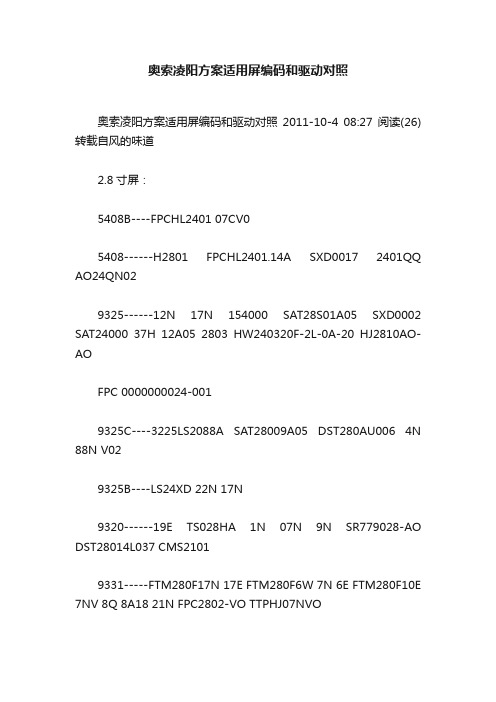
奥索凌阳方案适用屏编码和驱动对照奥索凌阳方案适用屏编码和驱动对照2011-10-4 08:27阅读(26)转载自风的味道2.8寸屏:5408B----FPCHL2401 07CV05408------H2801 FPCHL2401.14A SXD0017 2401QQ AO24QN029325------12N 17N 154000 SAT28S01A05 SXD0002 SAT24000 37H 12A05 2803 HW240320F-2L-0A-20 HJ2810AO-AOFPC 0000000024-0019325C----3225LS2088A SAT28009A05 DST280AU006 4N 88N V029325B----LS24XD 22N 17N9320------19E TS028HA 1N 07N 9N SR779028-AO DST28014L037 CMS21019331-----FTM280F17N 17E FTM280F6W 7N 6E FTM280F10E 7NV 8Q 8A18 21N FPC2802-VO TTPHJ07NVO1289-----JS28ND603C-FPC WST240320S280AV02 1298-----SK001V02 HL2802 36B 10N M30111A197 CMS2101-03A SX2.8C98-4_3-37C T28-A T28-B FPC4218-V0123225-----AU28 036 SXD0006 001 7C SAT2400 12A FPC2803-VO 28A03-VO 12A05 KK240037 0039-C 280NP04-04 3728E SX2.8T28-4_3-37H SXD0001PNL9328------T-0028-A61505V---LS28XD 21N 21E 07NVO A18 FPC1A0027-01-A SYM280T01-A093116----15400053909335IH----24008C18 0367781-----21VO 24N 11N 4N 10N 18V2 FPC-TTHJ07CVO CM012 81-36A 8B26 SY280CM0204535-----SXD00179331LG----Q365205----17V0 YSD FPC 28A03-V0 18V21505C----2.4TE8347-----46E FPC-FTM280C05N 61N 80E TP65K9320LG----SAT28008A18 8K1304 KFM529B21 SR7790928-A061505W----SAT28008A18-Q337502----16N 13N 16E 17E 13E 12N SXD00651297----SAT28009A1161505U-FTM----B21 FPA-SH9873-01A_56-PCB RO61505R(3062主控上用)S6D04M0----TF28001A68070-----NT4PTM3728B MHJ101V1 ZBH028GT-01 SXD00688347D-----ZBH028GT-06 FPC-FTM280C58W-008367-----ZBH028GT-02V18230----XY-2405-HSD10-V2 LC2803.1R61509----QXD028-1000-FB9328LG----07V9338-----91N TFT028E001 EY028CMIL-001-V029335LG----LS28003ILI9320----826709341-----T-280A03-B-16 YQ24TM41-36CLCM0154------2805-PR112-V22.4屏5408-----A024QN025408B----FPCHL2401 SAT24001005 NOATS-V019325-----FPC-S2 TM240320C1NFWCWC FP-29325C----25N3225----Q36 154002660 FTP240F17N FTP240F22N 8C 24N 25W V1 66N 3624A9328----SPT-024-0061298----SK001V02 10N M30111A1978347----FTP240C61N 46E 5N FTP240C65N 3624F 240C29N 240C09N M403A1079325B----22N LS24XD FPC-JTBJ05JUO1505C----XY-2.4TE-V161580----FTP240H25N FTO240HO 32N 04N 25N9335HY----AST24011C19 091110S61505BOE----AST24011C19L LS-100810背面7781----24N 11N 81-36A61505W----LS24Q35 24036095205----53F F240253F 17V09320----01-1D FPC-FTS240W01 JC T24-E T24-A29340----T24BDHJ71V1 240A28-A-16 40-36A 134 240A37-A FPC-FTM240C179N-00S6D04H0----36PIN SXD0066HX8230------LC32002.1 XY-2405 HSDIO-V34535------SXD00249341-----YQ24TM41-36C T-240A82-D-16261卡屏的屏驱动----32063.5寸ST2102----KR035PA5S VT320240S70-A350TMT035---15400T4500 HW320 158000300 S805037535C R0HS 3.5_FPC_10FTS350----735M2 SN570 FMFU-2F 413450017002 513450006002LQ035----8501显示屏编号与屏驱动对应表1 排线丝印侧面丝印驱动IC2 024-22V1 93203 24WIT36-FPC01 93204 1540001660 TS024HAADD04-00 5408B5 1540002660 9325C6 24008C05-V1 93257 AF240B-36B V1.0 AL240EI-3501 77878 AF-240B-2V4.1 AL-240B-S1 77879 AF283E1-37A V1.2 9320-2.810 AF240E1-36C V1.0 778511 AF240E1-36C V2.0 778512 AF283P3-37A V1.0 9325-2.813 CMS2101-03A 080815 080918-2801A背光片 540814 CMS2101-03A 080815 CMS2101 HCT003-280-41F背光片1298CMT304-1(1)-08 8 30 5408B15 CMS2101-3 932516 FPC-FTS240F01 FTS240H03 150517 FPC-FTS240D03 129818 FPC-FTS240D14 129819 FPC-FTP240CO9N FTS240B03 834720 FPC-FTS240W01 FTP240W47N 129821 FPC-FTM280P04N M30111A150 9325C-2.822 FPC-FTM280C05N 8347-2.823 FPC-FTM280F01N FTM280F01N-00 9320-2.824 FPC-FTM280F06W FPC-FTM280F06N-00 090313(背面)933125 FPC-FTM280F07N R61505-2.826 FPC-FTM280C13N 932527 FPC-FTM280P05N M403A486 9325C28 FPC-Y80032 V01 N0711-14-04 9325-2.829 FTP240D10N-01 0703 129830 FTP240D24N-00 090307 778131 FPC-FTP280P05N FTP280P14N-01背面 778132 FTP240W17N-03 080807 9325B33 FG0280FLW-0802-1 8347-2.834 FPC_HL_2401 540835 HL2801 5408-2.836 HL2402B 5408B CMO37 HL2402A 5409B CMO38 LDH240*320F08M 778539 LS2288A 6813-2.840 M30111A116 129841 M30111A059 932542 MFC-S07024 V02 834743 MT321TLLKJ-13 排线接口不同 9320B-2.844 SX-2.4CPT-9325 9325B45 SAT28009A5 9325C-2.846 STA28008A18 9331-2.847 XJ2402-V01 834748 XD028-V01 9325-2.849 XSY LL240-003-081024 R61505(2.4)50 ZCT-24FPC-S1 778551 ZCT-24FPC-S2 9325xp024cp25-36v0 9325hw240320f-0j-0c-10 9325m403a545 1298hw240400f-3a 5420ygg000240ns04-03 9325zc24t04m 9320kfm281e01 9320truly-c tft8k1081fpc-a1-e 9320cf024lgg31-36av1 9320huaruit-0033-a-fpc 9325huaruit-0012-b 9325af240B-36b 7787af-283e1-37av1.2 9320GIANTPLUS KFM281E01-1D 9320 GIANTPLUS KFM281E01-1B 9320CF024LGG31-36AV1 9320 GIANTPLUS KFM281101-1A 9320JLST24PV25-36A 9325ZC24T02 9325DST280CPT003 9325 2.8寸 13SX-2.8CPT-932502 9325 2.8寸 13BX280V003(B0XIANTICH) 9325 2.8寸 13NT4SGP3T28A 5408B 2.8寸 10NT4SGP3T28A AU9325 2.8寸 17NT4PC36728A-BL AU9325 2.8寸 17FPC-TGG000280NP04-07 9325 2.8寸 24LEB-DO428000028C1 9325 2.8寸 24CMS210-03 9325 2.8寸 12HW240320F-2D-0B-10 9325 2.8寸 12HW240320F-2D-0B-20 9325 触摸 13SAT28009A05 9325 2.8寸 13LS2288A 9325 2.8寸 13LS2289A 1505 2.8C寸 9LS2288A 9328 2.8寸 13FPC-FTP280P04N-00 9325 2.8C寸 13FPC-FTM280F0TN-00 61505 2.8寸 27FPC-FTPM280F09N-01、FTM240D17N-00 61505 2.8寸 27 FPC-FTM280F06W-00(FTM280F06N-00) 9331 2.8寸 32NTSAU3624A 5408B 2.4寸 10NT4SHY3624A 3225+HY 2.4寸 35024HAADD04 9325 2.4寸 13FPC-T240BQC 9325 2.4寸 13AF240E3-36D 9325 2.4寸 13(AL240E1-3S01) 9325 2.4寸SX-TGS240STCPYB00-00 7785 2.4寸 15(TGS240STCP-8V1,LDH240X320F008M)SX-2.4CPT-9325 9325 2.4寸 18(SX-TGS2.4CPT)FPC-FTS240D03-02 1298 2.4寸 6(FTP240D10N-02) 9325 2.4寸 13SX-TGS24C98-4:3-36B 1298 2.4寸 6FPC-BKS2401 1298 2.4寸 6SAT24009C05 9325 2.4寸 13SAT24009C05L 9325 2.4寸 13(18)KTM377A01-1A 1298 2.4寸 6SAT24009C05 9325 2.4寸 13TGG000240NS04-03 9325 2.4寸 18(13)(LCM-TGG000240NS04-03)FPC-TTHJ05E00XA 9325 2.4寸 27 (FECHTKONCPT24-9325)24008CIT-Q29 1505 2.4寸 37 1540003250(FMARK) 9325 2.4寸 26 T-0033-B(HUARUI) 9325 2.4寸 26T-0053-A 1297 2.4寸 30T-0033-B 68B(CPT) 2.4寸 26T-0012-B(T-0024-A) 9325 2.4寸 18 (T-0059-A)T-0028-A(HUARUI) 9325 2.8寸2X-GT009BL 7783 2.4寸 25JLST24IH81-36A 7781 2.4寸 25JST24TM25-36A 9328 2.4寸 13SX24C98-413-36B 1298 2.4寸 6(SX-TGS240SDCPET00-00)CF024LCD87-36AVO 7787 2.4寸 4AF240B-36B V1.0 7787 2.4寸 4凌达所有屏 9320 1T-0030 9320 2.4寸 1KT240FC-003B 9320 2.4寸 1FPC-FTS240W01 9320 2.4寸 1FPC1032 9320 2.4寸 124WIT36-FPC01 9320 2.4寸 1FPC-FTS240F01 1505 2.4寸PF240320F-2C-OA-30 8347 2.4寸FPC24T49-A1 9325 2.4寸FPC-TGG000280NP04-07 9325 2.8寸TSA24002C05 9325 2.4寸ST24TM25-36A V1.0 9325 2.4寸FPC-0047A2 9320 2.4寸排线丝印侧面丝印驱动ICAF240B-36B V1.0 :AL240EI-3501 7787AF-240B-2V4.1 : AL-240B-S1 7787AF283E1-37A V1.2 9320-2.8AF240E1-36C V1.0 7785AF240E1-36C V2.0 7785AF283P3-37A V1.0 9325-2.8FPC-FTS240F01 FTS240H03 1505FPC-FTS240D03 1298FPC-FTS240D14 1298FPC-FTP240CO9N FTS240B03 8347FPC-FTM280C05N 8347-2.8FPC-FTM280F01N FTM280F01N-00 9320-2.8 FPC-Y80032 V01 N0711-14-04 9325-2.8 FTP240D10N-01 0703 1298FTP240W17N-03 080807 9325BJLST24PV25-36A V1.0 9325T-0033-B 9325024-22V1 9320FPC_HL_2401 5408HL2801 5408-2.8MFC-S07024 V02 8347MFC-S07001 V04 932024WIT36-FPC01 9320MFC-M240702-A 9320XJ2402-V01 8347XD028-V01 9325-2.8ZCT-24FPC-S1 7785ZCT-24FPC-S2 9325LDH240*320F08M 77851540001660 TS024HAADD04-00 5408B1540002660 9325C24008C05-V1 9325MT321TLLKJ-13 排线接口不同 9320B-2.8SX-2.4CPT-9325 9325BCMS2101-3 9325CMS2101-03A 080815 080918-2801A背光片 540834 M30111A116 1298HW240320F-oj-oc-10 9325FPC24T49-A1 9325ZCT-24FPC-S2 9325NOAIS NT4SAU3624A V01 5408CMS057-2 @ HX(8347)T028 0741Z HL240HYF 0803 7787Hantech HR24F11#02 7787JYD-G5060 GWIL36S03240A-A恻边号GXBL240-019LL240-003 08031141 9325FPC-Y80030 V01 恻边号yxd02436l09 je-c068(b) 9320FPC-Y80030 V01 9320M30111A055 8347M403A107 8347DM2432003-001 这个是2.8的,37线,驱动9320FPC24T49-A1 2.4 9325AF240E1-36B V2.0 7785FPC-Q90044-1 2.8 9325QD -24034Bo-1 2.4 9325NOAIS NT4SAU36 24A V01JLST24CP25-36A 2.4 9325板号:MP-763C-SL V1.1 2005.12.16上位屏CM50011ACT6-01AL 2006/03/06 20针1.5寸元件排列:由上到下整齐一行:C11-C7-C5-C12-R1-R2-C1-C6-C2-C3-C21-C22-C23-C31-C4-C0-D1可代换下位屏:CD50006ACT6-27PIN 2005/10/24 27针元件排列:由上到下整齐一行:RL-CVLCD-CVB0A-CVB1A(这是个利用同尺寸不同针数进行的代换)板号:SD008-V2 2006-07-25-MDLU (ROCKCHIPS 2606A)原屏:CMT027 V1.0 2006-08-09 29针可用屏:FPC-S95012-1 V01 SZSUCCESS 06.01 29针板号:JR040_MAIN_V3.1 2007.04.17 (2608a JXD858)原屏:TFT-2.4-S3D 36PIN IL9320可用屏:DZX2.4-S2 V06 (2608A JXD859)资源:GAUO GASP29P03200-002-A-FPC SA VER 1.3(即屏侧边的标记)板号:SG243 V2 0703140941P2原屏:GIANTPLUS KFM281E01-1D可用:CF024LGG31-36AV1(36P,2.4')可用:GIANTPLUS KFM281E01-1B可用:TRULY-C TFT8K1081FPC-A1-E适用机型:纽曼K8 (2.0版)-ANYKA-AK3225。
士兰微 SD7880 说明书:具有 PWM 线性调光功能的单级原边控制高功率因数 LED 驱动芯
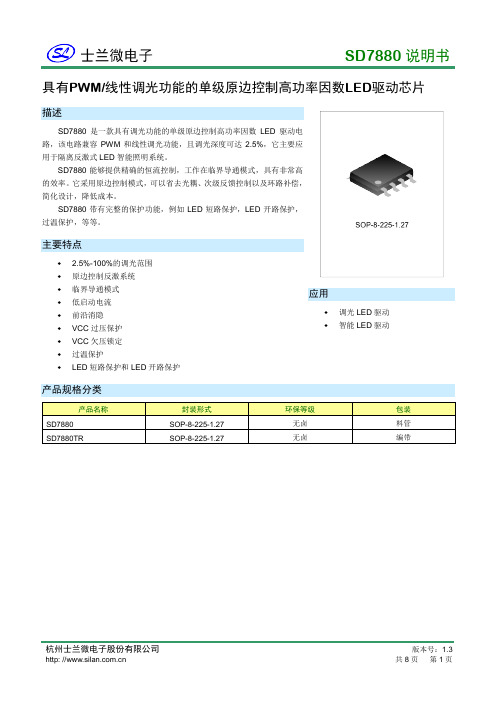
SD7880说明书具有PWM/线性调光功能的单级原边控制高功率因数LED 驱动芯片描述SD7880是一款具有调光功能的单级原边控制高功率因数LED 驱动电路,该电路兼容PWM 和线性调光功能,且调光深度可达2.5%,它主要应用于隔离反激式LED 智能照明系统。
SD7880能够提供精确的恒流控制,工作在临界导通模式,具有非常高的效率。
它采用原边控制模式,可以省去光耦、次级反馈控制以及环路补偿,简化设计,降低成本。
SD7880带有完整的保护功能,例如LED 短路保护,LED 开路保护,过温保护,等等。
主要特点♦ 2.5%-100%的调光范围 ♦ 原边控制反激系统 ♦ 临界导通模式 ♦ 低启动电流 ♦ 前沿消隐 ♦ VCC 过压保护 ♦ VCC 欠压锁定 ♦ 过温保护♦LED 短路保护和LED 开路保护应用♦ 调光LED 驱动 ♦智能LED 驱动产品规格分类产品名称封装形式 环保等级 包装 SD7880 SOP-8-225-1.27 无卤 料管 SD7880TRSOP-8-225-1.27无卤编带内部框图GNDVCCCSCOMPDR极限参数参 数符 号 参数范围 单位 电源电压 V CC -0.3 ~ 26.5 V DR 端电压 V DR -0.3 ~ 17.5 V PWM 端电压 V PWM -0.3 ~ 23 V ADIM 端电压 V ADIM -0.3 ~ 5.5 V COMP 端电压 V COMP -0.3 ~ 5.5 V 反馈电压 V FB -0.3 ~ 5.5 V 采样端电压 V CS -0.3 ~ 5.5 V 结温 T j -40~+150 °C 贮存温度范围 T stg-55~+150°C电气参数(除非特殊说明,VCC =23V,Tamb=25°C)管脚排列图管脚说明管脚号管脚名称I/O 功能描述1 COMP I/O 用RC环路补偿,跨导放大器输出端2 FB I 反馈电压检测脚3 CS I 电流采样脚4 GND I/O 地脚5 DRV O 栅驱动脚6 VCC I/O 芯片供电脚7 ADIM I 模拟调光脚8 PWM I PWM调光脚功能描述SD7880是一款具有调光功能的单级原边控制高功率因数LED驱动电路,该电路兼容PWM和线性调光功能,且调光深度可达2.5%,它主要应用于隔离反激式LED智能照明系统。
义隆中文资料 EM78P447S中文
8位 OTP 微控制器
产品规Байду номын сангаас书
版本 1.7
义隆电子股份有限公司
2009.11
本文内容是由英文规格书翻译 而来,目的是为了您的阅读更 加方便。它无法跟随原稿的更 新,文中可能存在翻译上的错 误,请您参考英文规格书以获 得更准确的信息。
商标告知:
IBM 为一个注册商标,PS/2 是 IBM 的商标之ㄧ.。
4.5 复位和唤醒 ..................................................................................................... 16
4.5.1 复位................................................................................................................... 16 4.5.2 状态寄存器的 RST, T, 和 P 的状态 ....................................................................... 20
Korea:
Elan Korea Electronics Company, Ltd.
301 Dong-A Building 632 Kojan-Dong, Namdong-ku Incheon City, KOREA Tel: +82 32 814-7730 Fax:+82 32 813-7730
深圳分公司:
香港分公司:
义隆电子(香港)有限公司 九龙观塘巧明街 95 号世达中心 19 楼 A 室 电话:+852 2723-3376 传真:+852 2723-7780
日本罗宾汉RUBICON型号汇总--华南区总代理
NO.160 NO.170 NO.180 NO.232 NO.1900 NO.18
NO.261 NO.262 NO.263 NO.650
NO.670 NO.5400 NO.5500 NO.950B NO.970B
NO.RES-910 NO.920 NO.RES-102 NO.103 NO.104 NO.105 NO.RSD-903
套装扳手系列
NO.RCW-307 NO.RCW-309 NO.RCW-311 NO.RCW-314
NO.RCW-317 NO.RCW-320
气动系列
NO.RDG-220 NO.RDG-250A NO.RD-100R NO.RD-130RJ
NO.RR-127 NO.RR-127J NO.RR-950T NO.RAH-220QC
NO.REA-S05~S35 NO.REA-P0000~P1 NO.REA-T3~T10 NO.REA-H07~H32
NO.REA-N18~N25 NO.RU-900 NO.901
六边星批系列
NO.181 NO.191
NO.161 NO.161-4
NO.161-6
钳子系列
NO.RS-150 NO.RS-170 NO.RS-200 NO.RML150 NO.RD-125
NO.RCA-150 NO.RCA-200 NO.RCA-250 NO.RJP-528 NO.RWC-100
NO.RGL-006 NO.RGL-010 NO.RGL-012 NO.RMC-008
NO.207 NO.204-W NO.205-W
彩条两用批系列
NO.50 NO.88 NO.624 NO.627 NO.637
瑞泰特RT8070 4A同步降压DC-DC转换器数据手册说明书

RT8070®©Copyright 2020 Richtek Technology Corporation. All rights reserved. is a registered trademark of Richtek Technology Corporation.General DescriptionThe RT8070 is a simple, easy-to-use current mode controlled 4A synchronous step-down DC-DC converter with an input supply voltage range from 2.7V to 5.5V. The device built-in an accurate 0.8V reference voltage and integrates low R DS(ON) power MOSFETs to achieve high efficiency in both WDFN-8L 3x3 and SOP-8 (Exposed Pad)packages.The RT8070 operates in automatic PSM that maintains high efficiency during light load operation. The device features cycle-by-cycle current-limit protection to prevent the device from the catastrophic damage in output short circuit, over-current or inductor saturation. Adjustable soft-start function prevents inrush current during start-up. The device also features input under-voltage lockout, output under-voltage protection, and over-temperature protection to provide safe and smooth operation in all operating conditions.Ordering Information4A, 2MHz, Synchronous Step-Down ConverterNote :Richtek products are :❝ RoHS compliant and compatible with the current require-ments of IPC/JEDEC J-STD-020.❝ Suitable for use in SnPb or Pb-free soldering processes.Features●Input Voltage Range from 2.7V to 5.5V ●Integrated 110m Ω and 70m Ω FETs●100% Duty Cycle for Lowest Dropout ●Power Saving Mode for Light Loads ●Adjustable Frequency : 200kHz to 2MHz ●0.8V Reference Allows Low Output Voltage ●Enable Function ●External Soft-Start ●Power Good Function●Input Under-Voltage Lockout Protection ●Output Under-Voltage Protection ●Over-Temperature Protection●RoHS Compliant and Halogen FreeZ : ECO (Ecological Element with Halogen Free and Pb free)Applications●LCD TVs and Monitors ●Notebook Computers●Distributed Power Systems ●IP Phones●Digital CamerasRT8070ZSP : Product NumberYMDNN : Date CodeRT8070ZSPMarking InformationRT8070ZQW25 : Product CodeYMDNN : Date CodeRT8070©Copyright 2020 Richtek Technology Corporation. All rights reserved. is a registered trademark of Richtek Technology Corporation.Typical Application CircuitTable 1. Recommended Components Selection for f= 1MHzPin Configuration(TOP VIEW)SOP-8 (Exposed Pad)COMPSS EN VINPGOOD FB LXRT WDFN-8L 3x3OUTNote:Considering the effective capacitance de-rated with biased voltage level and size, the C OUT component needs satisfy theeffective capacitance at least 15μF or above at targeted output level for stable and normal operation.RT8070©Copyright 2020 Richtek Technology Corporation. All rights reserved. is a registered trademark of Richtek Technology Corporation.Functional Pin DescriptionRT8070©Copyright 2020 Richtek Technology Corporation. All rights reserved. is a registered trademark of Richtek Technology Corporation.Functional Block DiagramRT8070©Copyright 2020 Richtek Technology Corporation. All rights reserved. is a registered trademark of Richtek Technology Corporation.Absolute Maximum Ratings (Note 1)●Supply Input Voltage, VIN ---------------------------------------------------------------------------------------------- −0.3V to 6V ●LX Pin Switch Voltage --------------------------------------------------------------------------------------------------- −0.3V to 6V <10ns ----------------------------------------------------------------------------------------------------------------------- −2.5V to 8.5V ●Other I/O Pin Voltages -------------------------------------------------------------------------------------------------- −0.3V to 6V ●Power Dissipation, P D @ T A = 25°CSOP-8 (Exposed Pad)--------------------------------------------------------------------------------------------------1.333W WDFN-8L 3x3-------------------------------------------------------------------------------------------------------------1.429W ●Package Thermal Resistance (Note 2)SOP-8 (Exposed Pad), θJA ---------------------------------------------------------------------------------------------75°C/W SOP-8 (Exposed Pad), θJC --------------------------------------------------------------------------------------------15°C/W WDFN-8L 3x3, θJA --------------------------------------------------------------------------------------------------------70°C/W WDFN-8L 3x3, θJC --------------------------------------------------------------------------------------------------------8.2°C/W ●Junction T emperature ----------------------------------------------------------------------------------------------------150°C ●Lead Temperature (Soldering, 10 sec.)------------------------------------------------------------------------------260°C●Storage T emperature Range ------------------------------------------------------------------------------------------- −65°C to 150°C ●ESD Susceptibility (Note 3)HBM (Human Body Model)---------------------------------------------------------------------------------------------2kVElectrical CharacteristicsRecommended Operating Conditions (Note 4)●Supply Input Voltage, VIN ----------------------------------------------------------------------------------------------2.7V to 5.5V ●Junction T emperature Range ------------------------------------------------------------------------------------------- −40°C to 125°C ●Ambient T emperature Range ------------------------------------------------------------------------------------------- −40°C to 85°CRT8070©Copyright 2020 Richtek Technology Corporation. All rights reserved. is a registered trademark of Richtek Technology Corporation.Note 1. Stresses beyond those listed “Absolute Maximum Ratings ” may cause permanent damage to the device. These arestress ratings only, and functional operation of the device at these or any other conditions beyond those indicated in the operational sections of the specifications is not implied. Exposure to absolute maximum rating conditions may affect device reliability.Note 2. θJA is measured at T A = 25°C on a high effective thermal conductivity four-layer test board per JEDEC 51-7. θJC ismeasured at the exposed pad of the package.Note 3. Devices are ESD sensitive. Handling precaution is recommended.Note 4. The device is not guaranteed to function outside its operating conditions.RT8070©Copyright 2020 Richtek Technology Corporation. All rights reserved. is a registered trademark of Richtek Technology Corporation.Typical Operating CharacteristicsSwitching Frequency vs. Temperature0.940.950.960.970.980.991.001.011.021.031.04-50-25255075100125Temperature (°C)S w i t c h i n g F r e q u e n c y (M H z )Output Voltage vs. Output Current1.0701.0751.0801.0851.0901.0951.1001.1051.1101.1151.1201.1251.13000.511.522.533.54Output Current (A)O u t p u t V o l t a g e (V)Reference Voltage vs. Temperature0.760.770.780.790.800.810.820.830.84-50-25255075100125Temperature (°C)R e f e r e n c e V o l t a g e (V)V IN UVLO vs. Temperature1.81.92.02.12.22.32.42.52.62.72.8-50-25255075100125Temperature (°C)V I N U V L O (V )Enable Voltage vs. Temperature0.60.70.80.91.01.11.21.31.41.51.6-50-250255075100125Temperature (°C)E n a b l e V o l t a g e (V )Efficiency vs. Output Current1020304050607080901000.0010.010.1110Output Current (A)E f f i c i e n c y (%)RT8070©Copyright 2020 Richtek Technology Corporation. All rights reserved. is a registered trademark of Richtek Technology Corporation.SwitchingTime (500ns/Div)V IN = 5V, V OUT = 1.1V, I OUT = 4AV LX (5V/Div)V OUT (10mV/Div)Power On from EN Time (500μs/Div)V EN (5V/Div)V OUT (1V/Div)I OUT (5A/Div)V PGOOD (5V/Div)V IN = 5V, V OUT = 1.1V, I OUT = 4A Load Transient ResponseTime (100μs/Div)V IN = 5V, V OUT = 1.1V, I OUT = 1A to 4A,R COMP = 10k Ω, C COMP = 560pFV OUT(200mV/Div)I OUT (2A/Div)Power Off from V INTime (5ms/Div)V IN (5V/Div)V OUT (1V/Div)I OUT (5A/Div)V PGOOD (5V/Div)V IN = 5V, V OUT = 1.1V, I OUT = 4A, EN = HighV IN (5V/Div)V OUT (1V/Div)I OUT (5A/Div)V PGOOD (5V/Div)Power On from V IN Time (2.5ms/Div)V IN = 5V, V OUT = 1.1V, I OUT = 4A, EN = HighPower Off from ENTime (250μs/Div)V EN (5V/Div)V OUT (1V/Div)I OUT (5A/Div)V PGOOD (5V/Div)V IN = 5V, V OUT = 1.1V, I OUT = 4ART8070©Copyright 2020 Richtek Technology Corporation. All rights reserved. is a registered trademark of Richtek Technology Corporation.Application InformationThe basic IC application circuit is shown in Typical Application Circuit. External component selection is determined by the maximum load current and begins with the selection of the inductor value and operating frequency followed by C IN and C OUT .Main Control LoopDuring normal operation, the internal upper power switch (P-MOSFET) is turned on at the beginning of each clock cycle. Current in the inductor increases until the peak inductor current reaches the value defined by the output voltage (V COMP ) of the error amplifier. The error amplifier adjusts its output voltage by comparing the feedback signal from a resistive voltage-divider on the FB pin with an internal 0.8V reference. When the load current increases,it causes a reduction in the feedback voltage relative to the reference. The error amplifier increases its output voltage until the average inductor current matches the new load current. When the upper power MOSFET shuts off,the lower synchronous power switch (N-MOSFET) turns on until the beginning of the next clock cycle.Output Voltage SettingThe output voltage is set by an external resistive voltage-divider according to the following equation :⨯OUT REF R1V = V (1+)R2where V REF equals to 0.8V typical.The resistive voltage-divider allows the FB pin to sense a fraction of the output voltage as shown in Figure 1.Figure 1. Setting the Output VoltageSoft-StartThe RT8070 provides adjustable soft-start function. The soft-start function is used to prevent large inrush current while converter is being powered-up. For the RT8070, the soft-start timing can be programmed by the external capacitor C SS between SS pin and ground. An internal current source I SS (10μA) charges an external capacitor to build a soft-start ramp voltage. The V FB will track the internal ramp voltage during soft start interval. The typical soft-start time is that V OUT rises from zero to 90% of setting value and can be calculated by the equation below :Power Good OutputThe power good output is an open-drain output and requires a pull up resistor. When the output voltage is 12.5% above or 12.5% below its set voltage, PGOOD will be pulled low. It is held low until the output voltage returns to within the allowed tolerances once more. During soft-start,PGOOD is actively held low and is only allowed to transition high when soft-start is over and the output voltage reaches 87.5% of its set voltage.Switching Frequency SettingThe RT8070 offers adjustable switching frequency setting and the switching frequency can be set by using external resistor RT . Switching frequency range is from 200kHz to 2MHz. Selection of the operating frequency is a tradeoff between efficiency and component size. High frequency operation allows the use of smaller inductor and capacitor values. Operation at lower frequencies improves efficiency by reducing internal gate charge and transition losses,but requires larger inductance values and capacitance to maintain low output ripple voltage. An additional constraint on operating frequency are the minimum on-time and minimum off-time. The minimum on-time, t ON_MIN , is the smallest duration of time in which the high-side switch can be in its “on ” state. This time is 90ns (typically). In continuous mode operation, the minimum on-time limit imposes a maximum operating frequency, f SW_MAX , of :f SW_MAX = V OUT / (t ON_MIN x V IN_MAX )SS SS SS0.8t = C I ⨯RT8070©Copyright 2020 Richtek Technology Corporation. All rights reserved. is a registered trademark of Richtek Technology Corporation.0.00.20.40.60.81.01.21.41.61.82.025050075010001250150017502000R RT (k Ω)S w i t c h i n g F r e q u e n c y (M H z )Figure 2. Switching Frequency vs. R RT Resistor Inductor SelectionFor a given input and output voltage, the inductor value and operating frequency determine the ripple current. The ripple current, ΔI L , increases with higher V IN and decreases with higher inductance OUT OUT L IN V V I =1f L V ⎡⎤⎡⎤∆-⎢⎥⎢⎥⨯⎣⎦⎣⎦Having a lower ripple current reduces not only the ESR losses in the output capacitors but also the output voltage ripple. Highest efficiency operation is achieved by reducing ripple current at low frequency, but attaining this goal requires a large inductor.For the ripple current selection, the value of ΔI L = 0.4(I MAX )is a reasonable starting point. The largest ripple current occurs at the highest V IN . To guarantee that the ripple current stays below a specified maximum value, the inductor value needs to be chosen according to the following equation :OUT OUT L(MAX)IN(MAX)V V L = 1f I V ⎡⎤⎡⎤-⎢⎥⎢⎥⨯∆⎢⎥⎢⎥⎣⎦⎣⎦Using Ceramic Input and Output CapacitorsHigher values, lower cost ceramic capacitors are now becoming available in smaller case sizes. Their high ripple current, high voltage rating and low ESR make them ideal for switching regulator applications. However, care must be taken when these capacitors are used at the input and output. When a ceramic capacitor is used at the input and the power is supplied by a wall adapter through long wires, a load step at the output can induce ringing at the input. At best, this ringing can couple to the output and be mistaken as loop instability. At worst, a sudden inrush of current through the long wires can potentially cause a voltage spike at V IN large enough to damage the part.Slope Compensation and Peak Inductor CurrentSlope compensation provides stability in constantfrequency architectures by preventing sub- harmonic oscillations at duty cycles greater than 50%. It is accomplished internally by adding a compensating ramp to the inductor current signal. Normally, the peak inductor current is reduced when slope compensation is added.For the IC, however, separated inductor current signal is used to monitor over-current condition, so the maximum output current stays relatively constant regardless of the duty cycle.Hiccup Mode Under-Voltage ProtectionA Hiccup Mode under-voltage protection (UVP) function is provided for the IC. When the FB voltage drops below half of the feedback reference voltage, V FB , the UVP function is triggered to auto re-soft-start the power stage until this event is cleared. The Hiccup Mode UVP reduces the input current in short circuit conditions, but will not be triggered during soft-start process.Under-Voltage Lockout ThresholdThe RT8070 includes an input under-voltage lockout protection (UVLO) function. If the input voltage exceeds the UVLO rising threshold voltage, the converter will reset and prepare the PWM for operation. However, if the inputwhere V IN_MAX is the maximum operating input voltage.Through external resistor RT connect between RT pin and ground to set the switching frequency f SW . The equation below shows the relation between setting frequency and RT value.The switching frequency vs R RT value can be short with the formula below : f SW (MHz) = K x 0.9 / R RT (k Ω),where K = 3.67 x 10⁵Note that the variation of f SW is ±15%.DS8070-09 November 2020©Copyright 2020 Richtek Technology Corporation. All rights reserved. is a registered trademark of Richtek Technology Corporation.voltage falls below the UVLO falling threshold voltage during normal operation, the device will stop switching. The UVLO rising and falling threshold voltage has a hysteresis to prevent noise caused reset.Over-Temperature ProtectionThe RT8070 includes an over-temperature protection (OTP)circuitry to prevent overheating due to excessive power dissipation. The OTP will shut down switching operation when junction temperature exceeds a thermal shutdown threshold T SD (150°C). Once the junction temperature cools down by a thermal shutdown hysteresis (ΔT SD = 20°C),the IC will resume normal operation with a complete soft-start.Thermal ConsiderationsFor continuous operation, do not exceed absolute maximum junction temperature. The maximum power dissipation depends on the thermal resistance of the IC package, PCB layout, rate of surrounding airflow, and difference between junction and ambient temperature. The maximum power dissipation can be calculated by the following formula :P D(MAX) = (T J(MAX) − T A ) / θJAwhere T J(MAX) is the maximum junction temperature, T A is the ambient temperature, and θJA is the junction to ambient thermal resistance.For recommended operating condition specifications, the maximum junction temperature is 125°C. The junction to ambient thermal resistance, θJA , is layout dependent. For SOP-8 (Exposed Pad) packages, the thermal resistance,θJA , is 75°C/W on a standard JEDEC 51-7 four-layer thermal test board. For WDFN-8L 3x3 packages, the thermal resistance, θJA , is 70°C/W on a standard JEDEC 51-7 four-layer thermal test board. The maximum power dissipation at T A = 25°C can be calculated by the following formulas :P D(MAX) = (125°C − 25°C) / (75°C/W) = 1.333W for SOP-8 (Exposed Pad) packageP D(MAX) = (125°C − 25°C) / (70°C/W) = 1.429W for WDFN-8L 3x3 packageThe maximum power dissipation depends on the operating ambient temperature for fixed T J(MAX) and thermal resistance, θJA . The derating curves in Figure 3 allow the designer to see the effect of rising ambient temperature on the maximum power dissipation.Figure 3. Derating Curve of Maximum Power Dissipation 0.00.10.20.30.40.50.60.70.80.91.01.11.21.31.41.50255075100125Ambient Temperature (°C)M a x i m u m P o w e r D i s s i p a t i o n (W )Layout ConsiderationsFollow the PCB layout guidelines for optimal performance of the IC.❝Connect the terminal of the input capacitor(s), C IN , as close to the VIN pin as possible. This capacitor provides the AC current into the internal power MOSFETs.❝LX node experiences high frequency voltage swings so should be kept within a small area.❝Keep all sensitive small signal nodes away from the LX node to prevent stray capacitive noise pick up.❝Connect the FB pin directly to the feedback resistors.The resistive voltage divider must be connected between V OUT and GND.©Copyright 2020 Richtek Technology Corporation. All rights reserved. is a registered trademark of Richtek Technology Corporation.Figure 4. PCB Layout GuidePlace the compensation C Place the feedbackresistors as close to as close to the IC as possible.CPlace the compensation C sEnsitive components away from this trace.Place the feedback resistors as close to as close to the IC as possible.C (a) For SOP-8 (Exposed Pad) package(b) For WDFN-8L 3x3 packageDS8070-09 November 2020©Copyright 2020 Richtek Technology Corporation. All rights reserved. is a registered trademark of Richtek Technology Corporation.Outline DimensionBFHMI(Bottom of Package)8-Lead SOP (Exposed Pad) Plastic PackageW-Type 8L DFN 3x3 PackageRichtek Technology Corporation14F, No. 8, Tai Yuen 1st Street, Chupei CityHsinchu, Taiwan, R.O.C.Tel: (8863)5526789Richtek products are sold by description only. Richtek reserves the right to change the circuitry and/or specifications without notice at any time. Customers should obtain the latest relevant information and data sheets before placing orders and should verify that such information is current and complete. Richtek cannot assume responsibility for use of any circuitry other than circuitry entirely embodied in a Richtek product. Information furnished by Richtek is believed to be accurate and reliable. However, no responsibility is assumed by Richtek or its subsidiaries for its use; nor for any infringements of patents or other rights of third parties which may result from its use. No license is granted by implication or otherwise under any patent or patent rights of Richtek or its subsidiaries.。
康奈德单体电池仪模块特殊寄存器
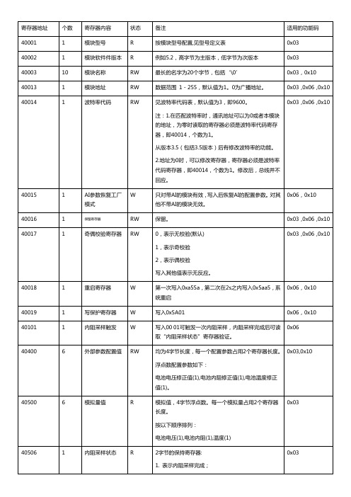
内阻采集触发规则:
1.为保证内阻采集结果的准确性,自单体模块上电时起,前4次触发内阻采集的数值不会保存,查询内阻值将会返回无效数值。
2.两次触发内阻采集动作的间隔至少在五分钟以上,否则将会有烧毁设备或电池的风险。
备注:(保留)
1.DI的值Bit0代表DI当前开关量输入状态。
其它Bit位保留,始终为0。
2.自动清零和手动清零并不冲突,设置了自动清零,相关可清0的寄存器仍然可以用手工清0。
3.每个寄存器的清0是独立的,相互不影响。
4.DO的状态写0xFF00表示输出1,0x0000表示输出0。
写其他值返回失败。
DO上电时的状态同理。
5.DO处于电平工作模式时,写对应的脉冲宽度寄存器无效果。
6.DO处于脉冲工作模式时,写对应DO的状态寄存器无效果。
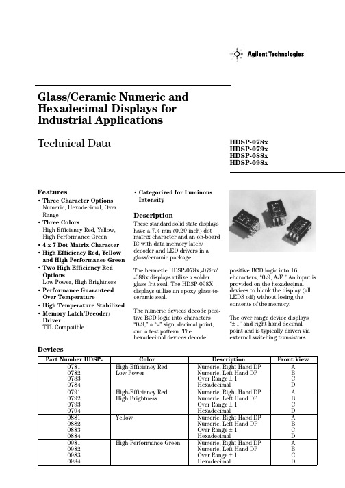
HDSP-078X中文资料
DevicesPart Number HDSP-ColorDescriptionFront View0781High-Efficiency Red Numeric, Right Hand DP A 0782Low Power Numeric, Left Hand DP B 0783Over Range ±1C 0784HexadecimalD 0791High-Efficiency Red Numeric, Right Hand DP A 0792High Brightness Numeric, Left Hand DP B 0793Over Range ±1C 0794HexadecimalD 0881YellowNumeric, Right Hand DP A 0882Numeric, Left Hand DP B 0883Over Range ±1C 0884HexadecimalD 0981High-Performance GreenNumeric, Right Hand DP A 0982Numeric, Left Hand DP B 0983Over Range ±1C 0984HexadecimalDHDSP-078x HDSP-079x HDSP-088x HDSP-098xFeatures• Three Character Options Numeric, Hexadecimal, Over Range• Three ColorsHigh Efficiency Red, Yellow,High Performance Green• 4x 7 Dot Matrix Character • High Efficiency Red, Yellow and High Performance Green • Two High Efficiency Red OptionsLow Power, High Brightness • Performance Guaranteed Over Temperature• High Temperature Stabilized • Memory Latch/Decoder/DriverTTL Compatible• Categorized for Luminous IntensityDescriptionThese standard solid state displays have a 7.4 mm (0.29 inch) dot matrix character and an on-board IC with data memory latch/decoder and LED drivers in a glass/ceramic package.The hermetic HDSP-078x,-079x/-088x displays utilize a solder glass frit seal. The HDSP-098X displays utilize an epoxy glass-to-ceramic seal.The numeric devices decode posi-tive BCD logic into characters “0-9,” a “–” sign, decimal point,and a test pattern. Thehexadecimal devices decodeGlass/Ceramic Numeric and Hexadecimal Displays for Industrial Applications Technical Datapositive BCD logic into 16characters, “0-9, A-F.” An input is provided on the hexadecimal devices to blank the display (all LEDS off) without losing the contents of the memory.The over range device displays “±1” and right hand decimal point and is typically driven via external switching transistors.COUNTRY CODEPackage DimensionsAbsolute Maximum RatingsNotes:1. The nominal thermal resistance of a display mounted in a socket that is soldered onto a printed circuit board isRθJA=50°C/W/device. The device package thermal resistance is RθJ-PIN = 15°C/W/device. The thermal resistance device pin-to-ambient through the PC board should not exceed 35°C/W/device for operation up to T A = +100°C.2. Voltage values are with respect to device ground, pin 6.3. These displays are categorized for luminous intensity with the intensity category designated by a letter code located on the back ofthe display package. Case temperature of the device immediately prior to the light measurement is equal to 25°C.Electrical/Optical Characteristics T A = –55°C to +100°CNotes:4. The luminous intensity at a specific operating ambienttemperature, I v(T A), may be approximated from the following exponential equation: I v(T A)=I v(25°C) e[k(T-25°C)].Device KHDSP-078 Series–0.0131/°CHDSP-079x SeriesHDSP-088x Series–0.0112/°CHDSP-098x Series–0.0104/°C 5. The dominant wavelength, λd, is derived from the CIE chroma-ticity diagram and represents the single wavelength whichdefines the color of the device.6. The HDSP-088X and HDSP-098X series devices are categor-ized as to dominant wavelength with the category designated by a number on the back of the display package.7. All typical values at V CC = 5.0 V and T A = 25°C.Operational ConsiderationsElectricalThese devices use a modified4x7 dot matrix of light emitting diodes to display decimal/ hexadecimal numeric informa-tion. The high efficiency red and yellow displays use GaAsP/GaP LEDs and the high performance green displays use GaP/GaP LEDs. The LEDs are driven by constant current drivers, BCD information is accepted by the display memory when the enable line is at logic low and the data islatched when the enable is atlogic high. Using the enable pulsewidth and data setup and holdtimes listed in the RecommendedOperating Conditions allows datato be clocked into an array ofdisplays at a 6.7MHz rate.The decimal point input is activelow true and this data is latchedinto the display memory in thesame fashion as the BCD data.The decimal point LED is drivenby the on-board IC.The blanking control input on thehexadecimal displays blanks(turns off) the displayedinformation without disturbingthe contents of display memory.The display is blanked at aminimum threshold level of 2.0volts. When blanked, the displaystandby power is nominally 250mW at T A = 25°C.The ESD susceptibility of the ICdevices is Class A of MIL-STD-883 or Class 2 of DOD-STD-1686and DOD-HDBK-263.AMechanicalThese displays are hermetically sealed for use in environments that require a high reliability device. These displays are designed and tested to meet a helium leak rate of5x10-8cc/sec.These displays may be mounted by soldering directly to a printed circuit board or insertion into a socket. The lead-to-lead pin spacing is 2.54 mm (0.100 inch) and the lead row spacing is 15.24 mm (0.600 inch). These displays may be end stacked with 2.54 mm (0.100 inch) spacing between outside pins of adjacent displays. Sockets such as Augat 324-AG2D (3 digits) or Augat 508-AG8D (one digit, right anglemounting) may be used.The primary thermal path forpower dissipation is through thedevice leads. Therefore, to insurereliable operation up to anambient temperature of +100°C,it is important to maintain abase-to-ambient thermalresistance of less than35°C watt/device as measured ontop of display pin 3.For further information onsoldering and post soldercleaning, see Application Note1027, Soldering LEDComponents.PreconditioningThese displays are 100% pre-conditioned by 24 hour storage at125°C, at 100°C for the HDSP-098x Series.Contrast EnhancementThese display devices aredesigned to provide an optimumON/OFF contrast when placedbehind an appropriate contrastenhancement filter. For furtherinformation on contrastenhancement, see ApplicationNote 1015, ContrastEnhancement for LEDDisplays.Over Range DisplayThe over range devices display“±1” and decimal point. Thecharacter height and packageconfiguration are the same as thenumeric and hexadecimaldevices. Character selection isobtained via external switchingtransistors and current limitingresistors.Absolute Maximum RatingsDescription Symbol Min Max Unit Storage Temperature, Ambient T S–65+125°C Operating Temperature, Ambient T A–55+100°C Forward Current, Each LED I F10mA Reverse Voltage, Each LED V R5VPackage DimensionsLuminous Intensity per LED(Digit Average) at T= 25°C Figure 3. Typical Driving Circuit.Notes:0: Line switching transistor in Figure 7 cutoff.1: Line switching transistor in Figure 7 saturated.X: ‘don’t care.’Electrical Characteristics T A = –55°C to +100°CColor Bin Limits (Dominant Wavelength)Note:Bin categories are established for classification of products. Productsmay not be available in all bin categories. Please consult your localAgilent Technologies representative./semiconductorsFor product information and a complete list ofdistributors, please go to our web site.For technical assistance call:Americas/Canada: +1 (800) 235-0312 or(916) 788-6763Europe: +49 (0) 6441 92460China: 10800 650 0017Hong Kong: (+65) 6756 2394India, Australia, New Zealand: (+65) 6755 1939Japan: (+81 3) 3335-8152 (Domestic/Interna-tional), or 0120-61-1280 (Domestic Only)Korea: (+65) 6755 1989Singapore, Malaysia, Vietnam, Thailand,Philippines, Indonesia: (+65) 6755 2044Taiwan: (+65) 6755 1843Data subject to change.Copyright © 2004 Agilent Technologies, Inc.Obsoletes 5964-6390EJuly 14, 20045988-2261EN。
WP智能多路巡检显示控制仪(8路MODBUS)参数地址表

002系统内部小数点110010S 003系统内部小数点210020S 004系统内部小数点310030S 005系统内部小数点410040S 006第1通道值2000001D 007第1通道小数点20010D 008第2通道值2002003D 009第2通道小数点20030D 010第3通道值2004005D 011第3通道小数点20050D 012第4通道值2006007D 013第4通道小数点20070D 014第5通道值2008009D 015第5通道小数点20090D 016第6通道值200A00B D 017第6通道小数点200B0D 018第7通道值200C00D D 019第7通道小数点200D0D 020第8通道值200E00F D 021第8通道小数点200F0D 022通道锁定特性20100D 023报警指示灯20110D 024上/下限报警状态字20120D 025显示通道号20130D 026通道锁定标志20140D 027AT1: 各通道显示时间20150RW 028AT2: 打印功能20160RW 029AT3: 打印间隔20170RW 030H01: 第1路上限报警值2018044RW 031HA01: 第1路上限报警回差值2019044RW 032L01: 第1路下限报警值201A044RW 033LA01: 第1路下限报警回差值201B044RW 034H02: 第2路上限报警值201C050RW 035HA02: 第2路上限报警回差值201D050RW 036L02: 第2路下限报警值201E050RW 037LA02: 第2路下限报警回差值201F050RW 038H03: 第3路上限报警值202005C RW 039HA03: 第3路上限报警回差值202105C RW 040L03: 第3路下限报警值202205C RW 041LA03: 第3路下限报警回差值202305C RW042H04: 第4路上限报警值2024068RW 043HA04: 第4路上限报警回差值2025068RW 044L04: 第4路下限报警值2026068RW 045LA04: 第4路下限报警值2027068RW 046H05: 第5路上限报警值2028074RW 047HA05: 第5路上限报警回差值2029074RW 048L05: 第5路下限报警值202A074RW 049LA05: 第5路下限报警回差值202B074RW 050H06: 第6路上限报警值202C080RW 051HA06: 第6路上限报警回差值202D080RW 052L06: 第6路下限报警值202E080RW 053LA06: 第6路下限报警回差值202F080RW 054H07: 第7路上限报警值203008C RW 055HA07: 第7路上限报警回差值203108C RW 056L07: 第7路下限报警值203208C RW 057LA07: 第7路下限报警回差值203308C RW 058H08: 第8路上限报警值2034098RW 059HA08: 第8路上限报警回差值2035098RW 060L08: 第8路下限报警值2036098RW 061LA08: 第8路下限报警回差值2037098RW 062CLK: 参数锁定20380RW 063DE: 仪表地址20390RW 064BT: 波特率203A0RW 065N01: 第1路是否显示203B0RW 066N02: 第2路是否显示203C0RW 067N03: 第3路是否显示203D0RW 068N04: 第4路是否显示203E0RW 069N05: 第5路是否显示203F0RW 070N06: 第6路是否显示20400RW 071N07: 第7路是否显示20410RW 072N08: 第8路是否显示20420RW 07301L0: 第1路分度号20430RW 07401L1: 第1路小数点20440RW 07501L2: 第1路第一报警方式20450RW 07601L3: 第1路第二报警方式20460RW 07701L4: 第1路冷补方式及光柱显示方式20470RW 07801P1: 第1路显示零点2048044RW 07901K1: 第1路显示比例2049003RW 08001UL: 第1路变送输出下限204A044RW 08101UH: 第1路变送输出上限204B044RW 08201LL: 第1路量程下限204C044RW 08301LH: 第1路量程上限204D044RW 08401LA: 第1路小信号切除204E002RW 08502L0: 第2路分度号204F0RW 08602L1: 第2路小数点20500RW 08702L2: 第2路第一报警方式20510RW 08802L3: 第2路第二报警方式20520RW08902L4: 第2路冷补方式及光柱显示方式20530RW 09002P1: 第2路显示零点2054050RW 09102K1: 第2路显示比例2055003RW 09202UL: 第2路变送输出下限2056050RW 09302UH: 第2路变送输出上限2057050RW 09402LL: 第2路量程下限2058050RW 09502LH: 第2路量程上限2059050RW 09602LA: 第2路小信号切除205A002RW 09703L0: 第3路分度号205B0RW 09803L1: 第3路小数点205C0RW 09903L2: 第3路第一报警方式205D0RW 10003L3: 第3路第二报警方式205E0RW 10103L4: 第3路冷补方式及光柱显示方式205F0RW 10203P1: 第3路显示零点206005C RW 10303K1: 第3路显示比例2061003RW 10403UL: 第3路变送输出下限206205C RW 10503UH: 第3路变送输出上限206305C RW 10603LL: 第3路量程下限206405C RW 10703LH: 第3路量程上限206505C RW 10803LA: 第3路小信号切除2066002RW 10904L0: 第4路分度号20670RW 11004L1: 第4路小数点20680RW 11104L2: 第4路第一报警方式20690RW 11204L3: 第4路第二报警方式206A0RW 11304L4: 第4路冷补方式及光柱显示方式206B0RW 11404PB: 第4路显示零点206C068RW 11504KK: 第4路显示比例206D003RW 11604UL: 第4路变送输出下限206E068RW 11704UH: 第4路变送输出上限206F068RW 11804LL: 第4路量程下限2070068RW 11904LH: 第4路量程上限2071068RW 12004LA: 第4路小信号切除2072002RW 12105L0: 第5路分度号20730RW 12205L1: 第5路小数点20740RW 12305L2: 第5路第一报警方式20750RW 12405L3: 第5路第二报警方式20760RW 12505L4: 第5路冷补方式及光柱显示方式20770RW 12605P1: 第5路显示零点2078074RW 12705K1: 第5路显示比例2079003RW 12805UL: 第5路变送输出下限207A074RW 12905UH: 第5路变送输出上限207B074RW 13005LL: 第5路量程下限207C074RW 13105LH: 第5路量程上限207D074RW 13205LA: 第5路小信号切除207E002RW 13306L0: 第6路分度号207F0RW 13406L1: 第6路小数点20800RW 13506L2: 第6路第一报警方式20810RW13606L3: 第6路第二报警方式20820RW 13706L4: 第6路冷补方式及光柱显示方式20830RW 13806P1: 第6路显示零点2084080RW 13906K1: 第6路显示比例2085003RW 14006UL: 第6路变送输出下限2086080RW 14106UH: 第6路变送输出上限2087080RW 14206LL: 第6路量程下限2088080RW 14306LH: 第6路量程上限2089080RW 14406LA: 第6路小信号切除208A002RW 14507L0: 第7路分度号208B0RW 14607L1: 第7路小数点208C0RW 14707L2: 第7路第一报警方式208D0RW 14807L3: 第7路第二报警方式208E0RW 14907L4: 第7路冷补方式及光柱显示方式208F0RW 15007P1: 第7路显示零点209008C RW 15107K1: 第7路显示比例2091003RW 15207UL: 第7路变送输出下限209208C RW 15307UH: 第7路变送输出上限209308C RW 15407LL: 第7路量程下限209408C RW 15507LH: 第7路量程上限209508C RW 15607LA: 第7路小信号切除2096002RW 15708L0: 第8路分度号20970RW 15808L1: 第8路小数点20980RW 15908L2: 第8路第一报警方式20990RW 16008L3: 第8路第二报警方式209A0RW 16108L4: 第8路冷补方式及光柱显示方式209B0RW 16208PB: 第8路显示零点209C098RW 16308KK: 第8路显示比例209D003RW 16408UL: 第8路变送输出下限209E098RW 16508UH: 第8路变送输出上限209F098RW 16608LL: 第8路量程下限20A0098RW 16708LH: 第8路量程上限20A1098RW 16808LA: 第8路小信号切除20A2002RW END11 22 33 44 -19999999 -19999999 -19999999 -19999999 -19999999 -19999999 -19999999 -19999999 -19999999 -19999999 -19999999 -19999999 -19999999 -19999999 -19999999 -19999999 -19999999 -19999999 -19999999 -19999999 -19999999 -19999999 -19999999 -19999999 -19999999 -19999999 -19999999 -19999999 -19999999 -19999999 -19999999 -19999999 -19999999 -19999999 -19999999 -19999999-19999999 -19999999 -19999999 -19999999 -19999999 -19999999 -19999999 -19999999 -19999999 -19999999 -19999999 -19999999 -19999999 -19999999 -19999999 -19999999 -19999999 -19999999 -19999999 -19999999 -19999999 15 -19999999 -19999999 -19999999 -19999999 -19999999 -19999999 -19999999 -19999999 -19999999 -19999999 -19999999 -19999999 -19999999 -19999999 -19999999 -19999999 -19999999 -19999999 -19999999 -19999999 -19999999 -19999999 -19999999 -19999999-19999999 -19999999 -19999999 -19999999 -19999999 -19999999 -19999999 -19999999 -19999999 -19999999 -19999999 -19999999 -19999999 -19999999 -19999999 -19999999 -19999999 -19999999 -19999999 -19999999 -19999999 -19999999 -19999999 -19999999 -19999999 -19999999 -19999999 -19999999 -19999999 -19999999 -19999999 -19999999 -19999999 -19999999 -19999999 -19999999 -19999999 -19999999 -19999999 -19999999 -19999999 -19999999 -19999999 -19999999 -19999999 -19999999-19999999 -19999999 -19999999 -19999999 -19999999 -19999999 -19999999 -19999999 -19999999 -19999999 -19999999 -19999999 -19999999 -19999999 -19999999 -19999999 -19999999 -19999999 -19999999 -19999999 -19999999 -19999999 -19999999 -19999999 -19999999 -19999999 -19999999 -19999999 -19999999 -19999999 -19999999 -19999999。
沃伦森电气系列产品型号
沃伦森电气(WARENSEN)多年来一直专注于输配电系统无功补偿、滤波及电力电子设备的研发、生产和工程实施。
公司引入德国先进制造工艺和技术,坚持“积木式设计理念模块化成套产品”的产品战略,全心全意打造行业最具价值品牌!公司所生产的:WUAPF、WRS-APF、WMPF-12系列有源滤波装置主要应用于谐波污染严重的工况下;WRS-IC(R)、WRS-CRT(S)、WMT(S)C、WMXC-12、WMC-12、WMC-35系列无功补偿装置主要应用于电网等无功负荷波动较小的工况下;WRS-SVG、WDSVG、WIDSVG、WMSVC、WTSVC主要应用于无功负荷波动剧烈、电压闪变严重的工况下。
以上系列产品均可针对单独工程具体设计并提供项目策划书。
公司坚持“产品如人品质量是生命”的质量理念,保证产品卓越品质,并把“完美的产品是艺术品”作为产品制造工艺的唯一准则。
沃伦森电气(WARENSEN)在引入德国技术发展的同时,更注重人才与自主技术的储备,坚持与科研院所合作,定向培训、学术交流,联合建立研发基地,不断进行技术创新,提高产品先进性,保持行业领先水平。
一流的团队,一流的质量,一流的服务是我们的动力和源泉。
沃伦森电气(WARENSEN)不仅要做一个制造高品质产品的生产商,还要做一个用户满意,高效反应机制,不断创新的服务提供商。
互惠互利,与用户共赢,是我们永远的追求和目标。
电容器+电抗器WRS-CR7-10/400V WRS-MKP10/400-3 WRS-CK-10/400-3WRS-CR7-15/400V WRS-MKP15/400-3 WRS-CK-15/400-3WRS-CR7-20/400V WRS-MKP20/400-3 WRS-CK-20/400-3WRS-CR7-25/400V WRS-MKP25/400-3 WRS-CK-25/400-3WRS-CR7-30/400V WRS-MKP30/400-3 WRS-CK-30/400-3 WRS-CR7-40/400V WRS-MKP40/400-3 WRS-CK-40/400-3 WRS-CR14-10/400V WRS-MKP10/400-3 WRS-CK-10/400-3 WRS-CR14-15/400V WRS-MKP15/400-3 WRS-CK-15/400-3 WRS-CR14-20/400V WRS-MKP20/400-3 WRS-CK-20/400-3 WRS-CR14-25/400V WRS-MKP25/400-3 WRS-CK-25/400-3 WRS-CR14-30/400V WRS-MKP30/400-3 WRS-CK-30/400-3 WRS-CR14-40/400V WRS-MKP40/400-3 WRS-CK-40/400-3 电容电抗模块产品(晶闸管)WRS-CRT7-30/2-400VWRS-CRT7-30/2-400VWRS-CRT7-30/1-400VWRS-CRT7-30/2-400VWRS-CRT7-60/2-400VWRS-CRT7-60/2-400VWRS-CRT7-60/1-400VWRS-CRT7-60/2-400VWRS-CRT7-60/1-400V WRS-CRT7-60/2-400V WRS-CRT7-90/1-400V WRS-CRT7-60/1-400V WRS-CRT7-90/1-400V WRS-CRT7-60/2-400V WRS-CRT7-60/1-400V WRS-CRT7-90/1-400V WRS-CRT7-60/1-400V WRS-CRT7-90/1-400V WRS-CRT7-60/1-400V WRS-CRT7-90/1-400V WRS-CRT7-90/1-400V WRS-CRT14-30/2-400V WRS-CRT14-30/2-400V WRS-CRT14-30/1-400V WRS-CRT14-30/2-400VWRS-CRT14-60/2-400V WRS-CRT14-60/2-400V WRS-CRT14-60/1-400V WRS-CRT14-60/2-400V WRS-CRT14-60/1-400V WRS-CRT14-60/2-400V WRS-CRT14-90/1-400V WRS-CRT14-60/2-400V WRS-CRT14-60/1-400V WRS-CRT14-90/1-400V WRS-CRT14-60/2-400V WRS-CRT14-60/1-400V WRS-CRT14-90/1-400V WRS-CRT14-60/1-400V WRS-CRT14-90/1-400V WRS-CRT14-60/1-400V WRS-CRT14-90/1-400VWRS-CRT14-90/1-400V电容电抗模块产品(接触器) WRS-CRS7-30/2-400VWRS-CRS7-30/2-400VWRS-CRS7-30/1-400VWRS-CRS7-30/2-400VWRS-CRS7-60/2-400VWRS-CRS7-60/2-400VWRS-CRS7-60/1-400VWRS-CRS7-60/2-400VWRS-CRS7-60/1-400VWRS-CRS7-60/2-400VWRS-CRS7-60/2-400V WRS-CRS7-60/1-400V WRS-CRS7-90/1-400V WRS-CRS7-60/2-400V WRS-CRS7-60/1-400V WRS-CRS7-90/1-400V WRS-CRS7-60/1-400V WRS-CRS7-90/1-400V WRS-CRS7-60/1-400V WRS-CRS7-90/1-400V WRS-CRS7-90/1-400V WRS-CRS7-400V WRS-CRS14-30/2-400V WRS-CRS14-30/2-400V WRS-CRS14-30/1-400V WRS-CRS14-30/2-400V WRS-CRS14-60/2-400V WRS-CRS14-60/2-400V WRS-CRS14-60/1-400V WRS-CRS14-60/2-400V WRS-CRS14-60/1-400V WRS-CRS14-60/2-400V WRS-CRS14-90/1-400V WRS-CRS14-60/2-400V WRS-CRS14-60/1-400V WRS-CRS14-90/1-400V WRS-CRS14-60/2-400V WRS-CRS14-60/1-400V WRS-CRS14-90/1-400V WRS-CRS14-60/1-400V WRS-CRS14-90/1-400V WRS-CRS14-60/1-400V WRS-CRS14-90/1-400V WRS-CRS14-90/1-400V 智能电容器WRS-IC-450/10WRS-IC-450/15WRS-IC-450/20WRS-IC-450/25WRS-IC-450/30WRS-IC-450/40WRS-IC-450/50WRS-IC-450/60WRS-IC-450/70智能电容器(电抗器) WRS-ICR7-480/10 WRS-ICR7-480/15WRS-ICR7-480/20WRS-ICR7-480/24WRS-ICR7-480/30WRS-ICR7-480/35WRS-ICR7-480/40WRS-ICR7-480/45WRS-APF模块产品WRS-APF25/400VWRS-APF35/400VWRS-APF50/400VWRS-APF60/400VWRS-APF75/400VWRS-APF100/400VWRS-SVG模块产品WRS-SVG50/400VWRS-SVG100/400V静止无功发生器WRS-SVG WDSVG-12/1000-N WDSVG-12/2000-N磁控式动态补偿滤波装置WMSVC-12/600-600-N WMSVC-12/1000-1000-N WMSVC-12/1200-1200-N WMSVC-12/600-600-W WMSVC-12/1000-1000-W WMSVC-12/1200-1200-W 高压无功补偿装置WMC-12/1000-3NWMC-12/1200-4NWMC-12/1600-4NWMC-12/2000-5NWMC-12/1000-3WWMC-12/1200-4WWMC-12/1600-4WWMC-12/2000-5W高压线路装置WMXC-6/50+100JWMXC-6/100+100J WMXC-6/200+100J WMXC-6/100+200JWMXC-6/100+100 WMXC-12/50+100J WMXC-12/100+100J WMXC-12/200+100J WMXC-12/100+200J WMXC-12/100+100低压有源滤波装置WUAPF-480/50-2N WUAPF-480/75-2N WUAPF-480/100-3N WUAPF-480/125-3N WUAPF-480/150-3N WUAPF-480/200-4N低压无功补偿装置WMTC-400/90-4N WMTC-400/120-3N WMTC-400/180-4N WMTC-400/240-4N WMTC-400/300-5N WMTC-400/360-6N WMTC-400/480-6N低压无源滤波装置WTSF400-100/3-N WTSF400-200/4-N WTSF400-300/5-N低压控制器WRS-DK-12TWRS-DK-21TWRS-DK-12SWRS-DK-21S高压控制器WRS-HK-700智能电容器控制器WRS-IK-200电容器综合保护单元WRS-HB-1000电能质量在线监测装置WRS-600S动态补偿调节开关WRS-TD1永磁式电容投切真空开关WRS-ZNT12/630-Y。
- 1、下载文档前请自行甄别文档内容的完整性,平台不提供额外的编辑、内容补充、找答案等附加服务。
- 2、"仅部分预览"的文档,不可在线预览部分如存在完整性等问题,可反馈申请退款(可完整预览的文档不适用该条件!)。
- 3、如文档侵犯您的权益,请联系客服反馈,我们会尽快为您处理(人工客服工作时间:9:00-18:30)。
PROJECT CODE: OGP/B-08/078
TOTAL-SINOCHEM XINCHENG SERVICE STATION PROJECT
扬州新城
WEEKLY REPORT 周报
DATE OF ACTIVITY 日期: 08/03/2009—14/03/2009
REPORT NO.报告号: WPR 08-078-04
1.
S I T E A C T I V I T I E S T H I S W E E K 本周工作
Jiangsu Jinling Construction Co., Ltd 江苏金陵建筑安装工程公司
Station building 站房
1) Finishing toilet ceiling hangs assemble
完成卫生间天花板安装
2) Finishing toilet lighting assembles
完成卫生间灯具安装
3) Finishing toilet ventilating fan assemble
完成卫生间排风扇安装
4) Finishing toilet cabine partitions assemble
完成卫生间隔断板安装
5) Finishing office lighting assembles
完成办公室灯具安装
6) Finishing office Installation of air-conditioning
完成办公室空调安装
7) Finishing office ceiling hangs assemble
完成办公室天花板吊顶
8) Finishing shop Installation of air-conditioning
完成便利店空调安装
9) Finishing shop lighting assembles
完成便利店照明灯具安装
10) Starting shop tiling (Liri 30%)
开始便利店地砖铺贴(Liri 30%)
11) Continuing water-proof construction of station roof
继续站房屋面防水层施工
T a n k p i t 罐池
1) Finishing fire-fighting room door installation
完成消防器材箱箱门安装
2) Finishing fire-fighting room metope plastering
完成消防器材箱墙面抹灰
3) Finishing discharge point ceramic tiles
完成卸油口瓷砖铺贴
C a n o p y a r e a 罩棚区
1) Finishing canopy aluminum gusset ceiling installation
完成罩棚区吊顶铝扣板安装 2) Finishing pump island install
完成加油岛安装
3) Continuing canopy water-proof construction of canopy roof (60%)
继续罩棚屋面防水层施工(60%)
O t h e r s 其它
1) Finishing south and north fence painting
完成外围围墙南北两侧墙面粉刷
2) Finishing forecourt ground concrete pouring
完成场坪混凝土浇筑
3) Finishing west fence cleaning
完成外围围墙西侧墙面清理
4) Finishing forecourt drainage ditch cover installation
完成场区排水沟盖板安装
2.
C O N C E R N S ,A C T I O N ,C O M M E N T S ;关注事件,现场行动,结果,建议
1) 现场罩棚区及便利店门头已完成前一工序,具备转序条件,B V 现场工程师已
通知史密斯适时进场施工,以免影响整体施工进度。
3.
M A I N A C T I V I T I E S N E X T W E E K 下周工作 S t a t i o n b u i l d i n g 站房
1) Continuing shop exterior wall painting
继续便利店内外墙涂料施工
2) Finishing shop glass door installed
完成便利店玻璃门安装
3) Starting shop Furniture installed
开始便利店家具门安装
4) Finishing station roof water-proof construction
完成站房屋面防水施工
C a n o p y a r e a 罩棚区
1) Starting canopy column decoration
开始罩棚立柱包装
O t h e r s 其它
1) Continuing auxiliary room roof water-proof construction
继续辅房屋面防水施工
2) Finishing pressure test for oil system
完成油管路第二次保压试验
3) Starting tank pit manhole tiling construction
开始罐池人孔井瓷砖铺贴
4.
S A F E T Y , H E A L T H A N D E N V I R O N M E N T A L S T A T U S ; H S E 记录
No major safety accident or other emergency issues occurred in this week, the safety days achieved is 7 working days. To date, the accumulated record is 36 working days. Following are the HSE status up to the current date: Accumulated Construction Days 累计施工周期 36
Accident No. 事故数
Environmental pollution污染事件No
Health problem 健康事件No Site HSE status descprition 现场HSE状况描述
The construction site of the HSE management work under control
现场施工H S E管理工作处于受控状态。
5.S I T E E Q U I P M E N T现场设备投入
6. S I T E M A N P O W E R 现场人员投入
7.
C O N S T R U C T I O N C O M F O R M I T Y R E P O R T P A S S E
D 施工符合性报告记录: THIS WEEK WITHOUT COMFORMITY REPORT 本周无符合性检查点
8. S I T E A U D I T P L A N
Next week: 15th
Mar . to 21st
Mar . Mr. Kong,xiangshu
9. A T T A C H M E N T
ANNEX 01 Digital Photo Reference (DPR 08-078-04) ANNEX 02 HSE audit list 08-078-04
Project Management: Bureau Veritas (Shanghai) Consulting Co., Ltd
Prepared by: Kong,xiangshu
Checked by: Liu, Wenbin
Validate by: Lu, Yi
Diffusion: TSO Date: 14/03/2009。
