DSP安装方法
惠威PX系列DSP处理器电脑软件使用说明书
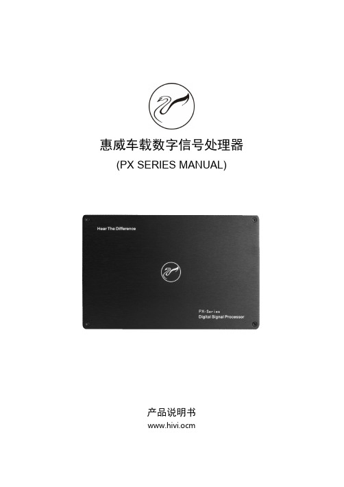
惠威车载数字信号处理器(PX SERIES MANUAL)产品说明书www.hivi.ocm中文(简)目录操作说明警告警告 (2)准备工作配件清单 (3)电脑软件电脑软件使用说明 (4)软件安装注意事项 (4)电脑软件主界面介绍 (4)控制界面 (4)电脑软件操作说明 (5)均衡器界面 (5)机器连接 (5)预置音效设定 (6)数据加密 (6)切换输入音源 (6)调整主音量 (6)切换输出通道 (7)设置输出通道EQ (7)设置均衡器 (7)设置分频器 (8)设置输出通道音量和相位 (8)选择输出通道类型 (8)配置输出信号功能 (8)设置延时 (9)混音&混频界面 (9)设置混音&混频......................................10手机软件手机软件使用说明 (11)主页界面 (11)高级设置界面 (12)延时界面 (12)通道界面 (12)EQ界面 (13)混音界面 (13)线控器线控器使用说明 (14)控制界面 (14)调整主音量 (14)预置音效设定 (14)机器介绍机器连接图示 (15)机器接口介绍 (16)技术参数指标技术规格 (17)功能参数 (17)产品中有害物质的名称及含量产品中有害物质的名称及含量 (18)操作说明发生问题时,请立即停止使用请将本产品送回到代销店或至电服务热线:400-090-9199寻求进一步处理办法。
不要使用使您驾驶时分心的功能任何影响注意力的功能操作都要等完全把车辆停放在安全地带之后才进行。
否则,将可能导致意外事故。
驾驶中必须使音量控制在还能听到车外警示音的水平如果音量太大造成紧急车辆的警报声,道路警告讯号(火车交叉口等)听不清是非常危险的,并可能导致意外事故。
另外,在汽车里用过大音量收听还可能导致听力受到伤害。
不要分解或改造否则,可能导致意外事故、火灾或触电。
不要让儿童触及螺栓或螺丝这样的小物体吞下小物体会引起严重的伤害。
DSP安装及使用说明
DSP安装及使用说明DSP(Digital Signal Processing)是数字信号处理的缩写,它是一种对数字信号进行处理、分析和操作的技术。
在不同的领域,如音频处理、图像处理、通信等方面都有广泛的应用。
下面是DSP的安装及使用说明:一、DSP安装3.完成安装:安装程序运行完毕后,点击“完成”按钮,完成DSP软件的安装。
二、DSP使用1.打开DSP软件:在安装完成后,可以从开始菜单或桌面快捷方式打开DSP软件。
双击图标即可运行软件。
2.导入数据:在DSP软件中,通常需要导入要处理的数据。
选择“文件”菜单中的“导入”选项,然后浏览并选择要导入的数据文件。
点击“打开”按钮完成导入。
3.进行信号处理:DSP软件提供了多种信号处理工具和算法。
在菜单或工具栏上选择适当的处理方法,然后应用到导入的数据上。
根据具体情况,可以进行滤波、频谱分析、时域分析、卷积等处理操作。
4.调整参数:在进行信号处理时,可以根据需要调整算法的参数。
通常,会有相关的选项和界面用于设置参数。
根据具体算法和处理目标,适当调整参数以达到最佳效果。
5.可视化结果:DSP软件通常提供了可视化工具,用于显示处理后的结果。
通过图表、波形、频谱图等方式,可以直观地观察信号处理的效果。
6.导出数据:在完成信号处理后,可以选择将处理后的数据导出。
通过“文件”菜单中的“导出”选项,选择导出数据的格式和路径,然后点击“保存”按钮完成导出操作。
7.保存项目:如果需要保存整个处理过程和结果,可以选择“文件”菜单中的“保存项目”选项。
选择保存的位置和文件名,保存整个项目的配置和数据。
注意事项:1.学习使用DSP软件时,可以参考软件自带的帮助文档或在线教程,了解具体功能和操作方法。
2.在进行信号处理时,需要根据实际需求选择合适的算法和方法,以及调整相关参数。
3.DSP软件通常需要一定的计算资源,对于处理大量数据或复杂算法,可能需要较高配置的计算机。
4.在操作过程中,要注意保存重要的数据和结果,以免丢失。
VisualDSP5.0安装步骤说明
实验讲义
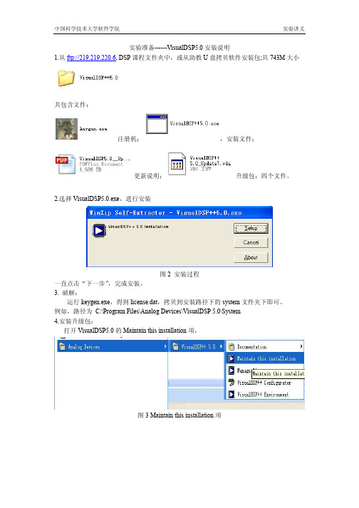
实验准备------VisualDSP5.0 安装说明 1.从 ftp://219.219.220.6, DSP 课程文件夹中,或从助教 U 盘拷贝软件安装包;共 743M 大小
共包含文件:
注册机;
,安装文件;
更新说明;
升级包;四个文件。
2.选择 VisualDSP5.0.exe,进行安装
图 2 安装过程 一直点击“下一步” ,完成安装。 3. 破解: 运行 keygen.exe,得到 license.dat,拷贝到安装路径下的 system 文件夹下即可。 例如,路径为 C:\Program Files\Analog Devices\VisualDSP 5.0\System 4.安装升级包: 打开 VisualDSP5.0 的 Maintain this installation 项,
图 3 Maintain this installation 项
中国科学技术大学软件学院
实验讲义
选择从本地安装更新,
图 4 选择本地更新包 点击“下一步” ,直到安装完成,至此,全部安装结束。
DSP仿真器用户手册
用户手册[V2.0]使用前请仔细阅读本手册第一章高速USB2.0接口TI DSP仿真器简介[V2.0]【产品特点】1、全新的硬件设计,真正双向过流过载保护,真正支持热插拨!!全新的电压检测电路,检测到目标板电压正常后再打开驱动电路,有效保护客户系统2、STA变色状态指示灯,目标板上电-->绿色;数据交换-->橙色,更清晰的状态指示3、双电源芯片设计,用于电源电路的高品质钽电容高达10颗,烧写、仿真调试非常稳定,支持最新的28335,280xx芯片,支持Vista系统4、同时兼容CCS2.X,CCS3.1、CCS3.2、CCS3.3等软件开发环境【仿真器引脚排布图示】【技术规格】· 采用高速版本USB2.0标准接口,即插即用,传输速度可达480MB/S,向下兼容USB1.1主机,直接采用USB 接口5.0V电源供电;· 标准14针Jtag仿真接口,不占用用户资源;特别接口安全保护设计,全面支持JTAG接口热插拔;· 支持Windows98/NT/2000/XP/VISTA操作系统;· 支持TI CCS2.X、支持CCS3.1、CCS3.2、CCS3.3集成开发环境,支持C语言和汇编语言;· 可对F28x/F240x/F24x/F20x系列的Flash进行编程,Flash烧写过程稳定可靠;· 仿真速度快,支持RTDX数据交换;· 不占用目标系统资源;· 自动适应目标板DSP电压,自动兼容3.3V、5V目标板;· 设计独特,完全克服目标板掉电后造成的系统死机;完全解决目标板掉电后不能重起CCS的问题;· 可仿真调试TI公司 TMS320C2000、TMS320C3000、TMS320C5000、TMS320C6000、3X、C4X、C5X、C8X及OMAP、DM642等全系列DSP芯片;· 支持多DSP 调试,一套开发系统可以对板上的多个DSP芯片同时进行调试;· 安装简单,运行稳定,价格低廉。
DSPbuilder安装指南(以9.1为例)
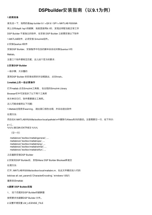
DSPbuilder安装指南(以9.1为例)1.前期准备⾸先说⼀下,我⽤的是dsp builder 9.1 +QII 9.1 SP1+ MATLAB R2009A⽹上没有dsp9.1sp1的破解,我是直接⽤9.1的,发现这样配也能正常⼯作DSP Builder 不是独⽴的软件,在安装 DSP Builder 之前需安装以下软件1.MATLAB软件,必须安装 Simulink组件。
2.安装Quartus II软件安装DSP Builder,安装程序中包含的脚本会⾃动关联Quartus II 和Matlab。
注意三个软件要相互匹配,这⼉给个官⽅的要求:2.安装DSP Builder⼀般步骤,⼤伙懂的直到DSP Builder 的安装结束的对话框跳出,点击finish。
3.matlab上的⼀些必要操作打开matlab 点击Simulink⼯具箱,在出现的Simulink LibraryBrowser栏中可发现多了以下两个⼯具库依次单击它们,软件需要建⽴⼯具库。
这⼉可能会碰到以下问题:1.Matlab出现很多warning ,跳出窗⼝报告出错,并⾃动退出软件处理⽅法:然后在X:\MATLAB\R2008a\toolbox\local\pathdef.m中删除与Altera有关的路径。
注意需要空⼀⾏,如下所⽰:p = [...%%% BEGIN ENTRIES %%%(空⼀⾏)matlabroot,'\toolbox\matlab\general;', ...matlabroot,'\toolbox\matlab\ops;', ...matlabroot,'\toolbox\matlab\lang;', ...matlabroot,'\toolbox\matlab\elmat;', ...matlabroot,'\toolbox\matlab\elfun;', ...之后重新安装DSP Builder2.安装完DSP Builder后,发现Altera DSP Builder Blockset库是空处理⽅法:打开..\MATLAB\R2008a\toolbox\local\matlabrc.m,在此⽂件最后加⼊代码bdclose all; set_param(0,'CharacterEncoding', 'windows-1252')重新启动matlab4.破解 DSP Builder流程1..找个匹配的DSP Builder的破解器按照要求先破解DSP Builder ⽂件。
20101211604Focusrite Safffire Pro 24DSP安装及MIX Control介绍
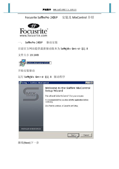
Focusrite Safffire Pr o 24DSP 安装及MixControl介绍一、Safffire Pr o 24DSP 驱动安装目前官方网站提供最新驱动版本为Saffire_M i x C ont r o l-1[1].8文件大小19.1MB开始安装驱动运行Saffire_M i x C ont r o l-1[1].8驱动程序继续(Next)下一步选择(I accept the agreement)我接受协议继续(Next)下一步继续(Next)下一步(Browse)浏览所安装的路径如不做更改继续(Next)下一步(Create a desktop icon)创建一个桌面图标(Create a Quick Launch icon)创建一个快速启动图标使用创建快捷图标请对应选项打钩不使用继续(Next)下一步继续(Install)安装下一步(Launch Saffire M ix c ont r o l A p pl i c a on) 启动Saffire Mixcontrol应用(View the Read Me) 查看自述不需要启动Saffire Mixcontrol程序继续(Finish) 完成需要启动Saffire Mixcontrol请勾选(Launch Saffire Mixcontrol Application)确保Safffire Pr o 24DSP 通过火线和计算机1394接口连接后打开Safffire Pr o 24DSP (机身右后侧)Power电源这时候计算机会自动装载Safffire Pr o 24DSP 驱动程序继续下一步完成继续下一步完成继续下一步完成现在Safffire Pr o 24DSP 驱动完全安装成功二、Safffire Pr o 24DSP 硬件介绍前面板1.XLR/TRS两用输入接口2.增益旋钮控制3.线路输入指示灯4.48V幻相供电开关5.FireWire或接收来自外部电源供应器电源指示灯6.设备与计算机连接指示灯7.时钟锁指示灯8.输入电平指示灯9.监听音量旋钮10.监听衰减和静音开关11.耳机1和2增益控制12.耳机1和2输出接口后面板1.TRS线路输入接口③④2.TRS输出接口①②③④⑤⑥3.光纤输入接口4.IEEE1394 6针的FireWire接口5.MIDI输入和输出插座6.电源开关7.直流电源输入插座只提供电源8.SPDIF输入和输出插座三、Safffire Pro 24DSP M ix C ont r o l 介绍启动Safffire M ix C ont r o l 控制面板现在我们就可以看到Safffire M ix C ont r o l 控制面板1.Mixer2.选择混合选项卡3.调音台输入通道4.选择混合输出通道5.路由和输入模式/Input FX / VRM Section6.监听控制部分7.设备状态四、MixControl使用每个组合可根据需要选择相应的混频器上按一下标签。
DSP并口仿真器安装说明-与2407芯片配套的
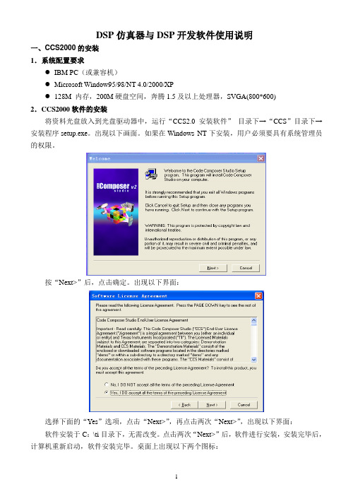
DSP仿真器与DSP开发软件使用说明一、CCS2000的安装1.系统配置要求●IBM PC(或兼容机)●Microsoft Window95/98/NT 4.0/2000/XP●128M 内存,200M硬盘空间,奔腾1.5及以上处理器,SVGA(800*600)2.CCS2000软件的安装将资料光盘放入到光盘驱动器中,运行“CCS2.0安装软件”目录下→“CCS”目录下→安装程序setup.exe。
出现以下画面。
如果在Windows NT下安装,用户必须要具有系统管理员的权限。
按“Next>”后,点击确定。
出现以下界面:选择下面的“Yes”选项,点击“Next>”,再点击两次“Next>”,出现以下界面:软件安装于C:\ti目录下,无需改变。
点击两次“Next>”后,软件进行安装,安装完毕后,计算机重新启动,软件安装完毕。
桌面上出现以下两个图标:3.硬件驱动程序安装及设置:(并口仿真器)运行光盘中“并口仿真器驱动程序”目录下→SetupCC2xx.exe程序,选择相应选项,软件安装于C:\tic2xx目录下。
安装完成后。
打开桌面上的“Setup CCS 2 ('C2000)”图标,出现如下界面。
点击“Close”后,删除左边“My System”下的文件。
点击右边的“Install a Device Driver”出现如下界面。
选择路经C:\ tic2xx\drivers显示如下图:选择“sdgo2xx.dvr”打开后确定。
软件中间栏出现一个“sdgo2xx.dvr”文件。
如下图所示:双击该文件出现如下界面。
点击“OK”后,进入下图界面,无需修改。
点击“Next >”,修改下一个界面中的I/O Port 值为0x378。
如下图。
再点击“Next >”,点击界面中的“Add Single”添加一个CPU组件,如下图:点击“Next >”,完成设置。
DSP仿真器安装说明
Copyright 2009 © yanxu. All rights recerved
南京研旭电气科技有限公司
�
每次执行 CCSv4 都会要求工作区目录。如果计划对所有项目使用一个目录,只需 选中“Use this as the default and do not ask again(默认使用此目录且不再询 问)”选项。以后随时可以在 CCSv4 中更改工作区。
� � � � � � � �
消除公共子表达式 软件流水 强度折减 自动增量寻址 基于成本的寄存器分配 指令预测 硬件循环 函数内联
Copyright 2009 © yanxu. All rights recerved
南京研旭电气科技有限公司
�
矢量化
TI 编译器还执行程序级别优化,在应用程序级别评估代码性能。通过程序级别视图, 编译器能够像具有完整系统视图的汇编程序开发人员一样生成代码。 编译器充分利用此应用 程序级别视图,找出能够显著提升处理器性能的折衷。 TI ARM 和 Microcontroller C/C++编译器经过专门针对代码大小和控制代码效率的 优化。它们具备行业领先的性能和兼容性。
操作步骤如下:
1、选择File——>Import命令(以YX-LED的一个工程为例);
Copyright 2009 © yanxu. All rights recerved
南京研旭电气科技有限公司
2、在弹出对话框中选择Legacy CCS3.3 Project,并单击Next按钮;
3、在弹出对话框中选择需要升级的CCSv3.3工程路径后,单击Next按钮;
由于这些差异,CCSv4 提供了一个“Import Legacy CCS Project Wizard(导入旧版 CCS 项目向导)”来帮助完成迁移。
DSPTMS320f240CCS安装设置流程

TIf240系列CCS安装步骤:1.将闻亭光盘放入光驱,USB连通计算机和仿真器,根据提示安装仿真器USB设备驱动程序;2.安装CCS2.2软件;3.双击闻亭安装盘上setup.exe,安装JTAG仿真器支持软件,安装目录置于CCS安装目录下;4.运行Setup Code Composer Studio;5.会自动弹出“Import Configuration”对话框(若没有,则点击右边窗口的Import a Configuration File),选择F24XX TDS510USB 2.0 Emulator –WintechDigital,点击Import,点击close;6.从右边窗口选择“Install a Device Driver”,在Drivers子文件夹下选择tixds24x.dvr,点击打开;7.右键单击左侧窗口“F24XX TDS510USB 2.0 Emulator – WintechDigital”项,从弹出的菜单中选择“Property”,弹出Board Properties对画框;8.在“Board Properties”窗口点击“Auto-generate board data file”,并通过下拉选择框将它改成“Auto-generate board data file with extraconfiguration file”(见图一)。
点击下面的“Browse”按钮,找到你的CCS所在的目录,(缺省路径是C:\TI\cc\bin)选择“Wtusb5102.cfg”按“Open”按钮;图一9.点击“Next”按钮,选择端口号为0x240,(见图二);图二10.点击“Next”按钮,根据目标板DSP 的种类和数量,按“Add Single”或“Add Multiple”添加相应的DSP。
(一般此步可略过);11.点击“Next”按钮,出现选择gel 文件窗口。
按“…”按钮选择CC\gel\f240. gel 文件,按“Finish”按钮结束设置;12.保存并关闭CCS Setup,连接JTAG仿真器并将目标板上电,然后启动Code Composer Studio,至此,设置完成。
DSP BIOS LINK DRA44x + DM6437 LNK 191 USR 安装指南说明书
INSTALLATION GUIDEDSP/BIOS™ LINKDRA44x + DM6437LNK 191 USRVersion 1.65Document Template Version 1.4This page has been intentionally left blank.IMPORTANT NOTICETexas Instruments Incorporated and its subsidiaries (TI) reserve the right to make corrections, modifications, enhancements, improvements, and other changes to its products and services at any time and to discontinue any product or service without notice. Customers should obtain the latest relevant information before placing orders and should verify that such information is current and complete. All products are sold subject to TI’s terms and conditions of sale supplied at the time of order acknowledgment.TI warrants performance of its hardware products to the specifications applicable at the time of sale in accordance with TI’s standard warranty. Testing and other quality control techniques are used to the extent TI deems necessary to support this warranty. Except where mandated by government requirements, testing of all parameters of each product is not necessarily performed.TI assumes no liability for applications assistance or customer product design. Customers are responsible for their products and applications using TI components. To minimize the risks associated with customer products and applications, customers should provide adequate design and operating safeguards.TI does not warrant or represent that any license, either express or implied, is granted under any TI patent right, copyright, mask work right, or other TI intellectual property right relating to any combination, machine, or process in which TI products or services are used. Information published by TI regarding third–party products or services does not constitute a license from TI to use such products or services or a warranty or endorsement thereof. Use of such information may require a license from a third party under the patents or other intellectual property of the third party, or a license from TI under the patents or other intellectual property of TI.Reproduction of information in TI data books or data sheets is permissible only if reproduction is without alteration and is accompanied by all associated warranties, conditions, limitations, and notices. Reproduction of this information with alteration is an unfair and deceptive business practice. TI is not responsible or liable for such altered documentation.Resale of TI products or services with statements different from or beyond the parameters stated by TI for that product or service voids all express and any implied warranties for the associated TI product or service and is an unfair and deceptive business practice. TI is not responsible or liable for any such statements.Mailing Address:Texas InstrumentsPost Office Box 655303Dallas, Texas 75265Copyright ©. 2003, Texas Instruments IncorporatedThis page has been intentionally left blank.TABLE OF CONTENTSA.INTRODUCTION (6)1Purpose (6)2Text Conventions (6)3Terms & Abbreviations (6)4References (6)5Configuring CCS (7)5.1DRA44x EVM (7)6Platform specific information (7)6.1Flashing DM6437 (7)6.2EDMA resource requirements for DM6437 over VLNQ (10)A.INTRODUCTION1 PurposeDSP/BIOS™ LINK is foundation software for the inter-processor communication across the GPP-DSP boundary. It provides a generic API that abstracts the characteristics of the physical link connecting GPP and DSP from the applications. It eliminates the need for customers to develop such link from scratch and allows them to focus more on application development.This document provides the users necessary information to install DSP/BIOS™ LINK on the development host.This document corresponds to the product release Version 1.65.2 Text ConventionsO This bullet indicates important information.Please read such text carefully.q This bullet indicates additional information.[ arg1 | arg2 ] In context of the commands, contents enclosed in squarebrackets are the optional arguments to the command.Different values of these arguments are separated by “|”.3 Terms & AbbreviationsCCS Code Composer StudioIPC Inter Processor CommunicationGPP General Purpose e.g. ARMDSP Digital Signal Processor e.g. TMS320C5510CGTools Code Gen Tools, e.g. Compiler, Linker, Archiver4 References1. User Guide DSP/BIOS™ LINK user guideInstallation guide for relevant OS if present.2. InstallGuide_<OS>_Jacinto_DM6437_VLYNQ.pdf3. Porting Guide Porting guide for relevant OS if present.5 Configuring CCS5.1 DRA44x EVMTo use CCS for debugging the DSP side application, you will need to configure CCS to use both ARM and DSP with the EVM.q CCS can attach to only ARM in the beginning. It can attach to the DSP only after the ARM-side application releases it from reset through a call toPROC_Start ().6 Platform specific information6.1 Flashing DM6437VLYNQ module on DM6437 needs to be powered on so that ARM on DRA44x canaccess the DM6437 via VLYNQ. This can be done in two ways either using GEL file on DM6437 or flashing the NAND of DM6437 with initialization code. Here we will be describing the later.O DM6437 has problems with NAND bootmode, so we will use I2C bootmode and secondary bootloader mechanism.We will use the AIS script to flash the I2C and NAND of DM6437. Steps are as follows:pile secondary boot (customize if required)e genAIS utility to create AIS bootable image for secondary boot code fromI2C/SPIpile application code.e genAIS utility to create binary AIS bootable image of application codefrom NAND.e NAND Writer utility to write application AIS image to NAND flash.e I2C Writer utility to write secondary boot AIS image to EEPROM.7.Set BOOTMODE [3:0] = 1001b to select boot from I2C.8.Issue POR reset to DM6437 device.Following steps are described in the NANDSecondaryBoot.doc in the zip file from the link below:/dsp/docs/dspsupporttechdocsc.tsp?sectionId=3&tabId=409&fami lyId=1301&abstractName=spraag0dThe initialization code is below:#include "stdio.h"volatile unsigned int * bootAddr = (unsigned int *) 0x1C40008 ;volatile unsigned int * bootCmplt = (unsigned int *) 0x1C4000C ;#define PSC_BASE 0x01C41000#define PSC_EPCPR *( unsigned int* )( 0x01C41070 )#define PSC_PTCMD *( unsigned int* )( 0x01C41120 )#define PSC_PTSTAT *( unsigned int* )( 0x01C41128 )#define PSC_MDSTAT_BASE ( 0x01C41800 )#define PSC_MDCTL_BASE ( 0x01C41A00 )#define BOOTCFG *( unsigned int* )( 0x01C40014 )#define PINMUX0 *( unsigned int* )( 0x01C40000 )#define PINMUX1 *( unsigned int* )( 0x01C40004 )#define VDD3P3V_PWDN *( unsigned int* )( 0x01C40048 )#define PCISLVCNTRL *( unsigned int* )( 0x01C1A180 )#define PCICFGDONE *( unsigned int* )( 0x01C1A3AC )typedef void (*PC) () ;/* ------------------------------------------------------------------------ ** ** main( ) ** ** ------------------------------------------------------------------------ */ void main( void ){int i ;PC pcReg ;if ( ( BOOTCFG & 0x00020000 ) == 0 ){PINMUX0 = 0x00148001;/*| ( 0 << 30 ) // CI10SEL - No CI[1:0]| ( 0 << 28 ) // CI32SEL - No CI[3:2]| ( 0 << 26 ) // CI54SEL - No CI[5:4]| ( 0 << 25 ) // CI76SEL - No CI[7:6]| ( 0 << 24 ) // CFLDSEL - No C_FIELD| ( 0 << 23 ) // CWENSEL - No C_WEN| ( 0 << 22 ) // HDVSEL - No CCDC HD and VD| ( 1 << 20 ) // CCDCSEL - CCDC PCLK, YI[7:0] enabled | ( 4 << 16 ) // AEAW - EMIFA full address mode| ( 1 << 15 ) // VPBECLK - VPBECLK enabled| ( 0 << 12 ) // RGBSEL - No digital outputs| ( 0 << 10 ) // CS3SEL - LCD_OE/EM_CS3 disabled| ( 0 << 8 ) // CS4SEL - CS4/VSYNC disabled| ( 0 << 6 ) // CS5SEL - CS5/HSYNC disabled| ( 0 << 4 ) // VENCSEL - Video encoder outputs disabled | ( 1 << 0 );*/// AEM - 8-bit EMIFA, 8-bit CCDC in}/** PINMUX settings for PCI operation*/if ( ( BOOTCFG & 0x00020000 ) != 0 ){PINMUX0 = 0x00148000;/*| ( 0 << 30 ) // CI10SEL - No CI[1:0]| ( 0 << 28 ) // CI32SEL - No CI[3:2]| ( 0 << 26 ) // CI54SEL - No CI[5:4]| ( 0 << 25 ) // CI76SEL - No CI[7:6]| ( 0 << 24 ) // CFLDSEL - No C_FIELD| ( 0 << 23 ) // CWENSEL - No C_WEN| ( 0 << 22 ) // HDVSEL - No CCDC HD and VD| ( 1 << 20 ) // CCDCSEL - CCDC PCLK, YI[7:0] enabled| ( 4 << 16 ) // AEAW - EMIFA full address mode| ( 1 << 15 ) // VPBECLK - VPBECLK enabled| ( 0 << 12 ) // RGBSEL - No digital outputs| ( 0 << 10 ) // CS3SEL - LCD_OE/EM_CS3 disabled| ( 0 << 8 ) // CS4SEL - CS4/VSYNC disabled| ( 0 << 6 ) // CS5SEL - CS5/HSYNC disabled| ( 0 << 4 ) // VENCSEL - Video encoder outputs disabled | ( 0 << 0 );*/// AEM - N/A}PINMUX1 = 0x01618530;/*| ( 1 << 24 ) // SPBK1 - McBSP1 enabled| ( 1 << 22 ) // SPBK0 - McBSP0 enabled| ( 2 << 20 ) // TIM1BK - UART1 enabled, Timer1 disabled | ( 1 << 16 ) // TIM0BK - Timer0 enabled| ( 2 << 14 ) // CKOBK - CLKOUT disabled, PWM2 enabled | ( 0 << 12 ) // PWM1BK - PWM1 disabled, GIO84 enabled | ( 1 << 10 ) // UR0FCBK - UART0 HW flow control enabled | ( 1 << 8 ) // UR0DBK - UART0 data enabled| ( 3 << 4 ) // HOSTBK - VLYNQ + MII + MDIO Mode| ( 0 << 0 );*/// PCIEN - PCI disabledVDD3P3V_PWDN = 0x00000000; // Everything onfor ( i = 0 ; i <= 9 ; i++ )*( unsigned int* )( PSC_MDCTL_BASE + 4 * i ) |= 0x0003;for ( i = 11 ; i <= 28 ; i++ )*( unsigned int* )( PSC_MDCTL_BASE + 4 * i ) |= 0x0003;i = 39;*( unsigned int* )( PSC_MDCTL_BASE + 4 * i ) |= 0x0003;PSC_PTCMD = 0x0001;while( ( PSC_PTSTAT & 0x0001 ) );if ( ( BOOTCFG & 0x00020000 ) != 0 ){PCICFGDONE |= 1;PCISLVCNTRL |= 1;}while (1) {if (*bootCmplt & 0x1) {*bootCmplt = 0 ;break ;}}pcReg = (PC) (*bootAddr) ;(*pcReg) () ;}Create a project and compile the above file and follow the steps as specified in the NAND flashing sections.6.2 EDMA resource requirements for DM6437 over VLNQBy default, DSPLINK uses the following resources of DRA44x EDMA to achieve DMAbetween host and DM6437 connected over VLNQ interface.EDMA Channel 0.Shadow region 0EDMA Param Entry 0Interrupt Set/Pending bits: Bit0Event number: 0 (I.e. Bit0 of these registers: ISER, ICR, IPR, EESR, ESR)TC value 0q Application writers can change the EDMA channel ID by modifying the arg5 of LINKCFG_dspObject in the platform configuration file.All other resources used by this channel are defaults/user programmed values (likequeue etc)。
DSP软件安装
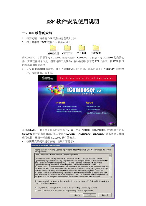
DSP软件安装使用说明一、CCS软件的安装1、打开光驱,将带有DSP软件的光盘放入其中。
2、打开其中的“DSP软件”目录显示如下:在C2000V2。
2目录下是CCS2000的安装软件;C5000V2。
2目录下是CCS5000的安装软件。
工具软件目录下是一些常用的工具软件;驱动程序目录下是EPP(并口)和USB接口的仿真器的驱动程序。
3、先安装CCS2000的软件,打开“C2000V2。
2”目录,点其目录下的“SETUP”应用程序。
安装开始。
如下图:在INSTALL下面有两个可选的安装项目,第一个是“CODE COMPOSER STUDIO”这是CCS2000软件的安装目录。
第二个是“ADOBE ACROBA T READER”是其帮助文件的应用软件。
选第一项进行CCS2000软件的安装。
4、按照其安装提示进行安装,出现如下提示:在下方选择“YES,IDO ACCEPT ALL THE TEMS OF THE PRECEDING LICENSE AGREEMENT”点击“NEXT”继续进行安装,直至出现如下图所示画面:在上图中有两个可选项,上面一个是CCS2000的安装软件(CODE COMPOSER STUDIO),下面一个是其软件的帮助文件的安装(ONLINE MANUALS)。
将两个项目都选择,即在两个项目前的方框内打上“√”;或者点击“SELECT ALL”点击“NEXT”继续进行安装。
出现如下图所示画面:在上图中选择“BROWSE”对软件的安装目录进行设置。
因为还有CCS5000的软件要进行安装,所以最好对其安装目录进行设置如C:/TI/2000,以示对CCS5000的区别。
点击“NEXT”继续进行安装,按照安装提示直至安装完成。
安装完成后会出现如下所示:点击“确定”按钮,出现如下图所示的窗口:这两项是安装完成后,其软件的网上资料和安装生成的一些介绍。
可以选择的来进行设置。
最后点击“FINISH”完成软件的安装。
DSP仿真器ICETEK-5100USB_V2.0A驱动安装过程
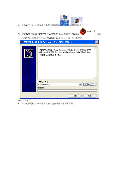
1、安装CCS3.1,安装完成后桌面出现两图标和。
2、安装DSP仿真器(ICETEK-5100USB V2.0A)配套的USB驱动。
双击
该图标后,目标文件夹选择CCStudio 3.1的安装目录,如下图所示。
点击“安装”。
3、将仿真器通过USB线接入电脑,会自动弹出下图所示界面。
如果不能自动弹出,可以右击“我的电脑”-“属性”-“设备管理器中”手动安装。
上图中,选择“否,暂时不”,点击“下一步”。
选择“从列表或制定位置安装(高级)”,点击“下一步”。
按上图所示做相关设置。
点击“下一步”。
点击“完成”,会自动再弹出下图所示对话框。
选择“否,暂时不”,点击“下一步”。
这时直接点击“下一步”自动安装。
这时仿真器USB驱动安装完毕。
4、将仿真器数据线接入PCB板(TMS320F2812为核心),上电。
5、双击,弹出下图界面。
选择左数第一个下拉菜单为“F28xx”,弹出下图所示界面。
双击,添加,如下图所示。
右击,选择“Properties”,无须改动,使用下图所示的默认设置。
点击next
单击“Finish”,右击,单击“Properties”,弹出下图所示界面。
GEL File文件的选择参考上图。
点击“OK”。
设置完毕。
6、启动CCS3.1,弹出下图所示界面。
点击下拉菜单“Debug”-“Connect”,仿真器连接上了,如下图所示。
南京理工大学谭彩铭
tancm@
2009-7-23整理。
奥迪Q5L的DSP安装教程
奥迪Q5L的DSP安装教程
一、无损改性材料
1.改装车型:奥迪q5
2.修改配置:1个音频处理器,带8音X1S和DSP无损数字功率放大器
3.安装时间:约30分钟
4.改装步骤:将专用车专用线束相互插接,连接电脑进行调校。
二、奥迪q5改装音响的步骤
1.安装8音X1S DSP直接将原厂功放插上专用车专用线束,即可完成8音DSP功放声音处理器的安装。
整个安装过程不断线,也不更换原装喇叭,可以节省更多费用。
8音音效处理器体积小巧,功能强大,内置4X65W四通道功放输出+高品质音频处理器+强大调音功能,可激发原车扬声器释放最佳潜能,带来清晰、通透、鲜明的音质效果。
2.接线完成后,连接电脑进行音频调试。
8音X1S DSP功放声音处理器拥有10个EQ调音功能,并独立调节声场延迟和相位,使声音层次清晰通透,每个细节都能听得一清二楚,声音的空感非常好,给人身临其境的感觉。
CAR多媒体拉斯维加斯900 DSP拉斯维加斯1000 DSP操作和安装说明说明书
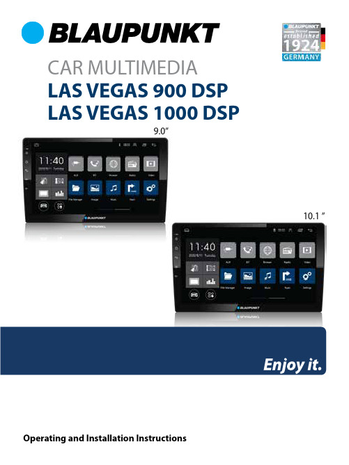
CAR MULTIMEDIA LAS VEGAS 900 DSP LAS VEGAS 1000 DSP10.1 ”9.0”CAUTIONSSafety NotesThis car radio has been manufactured according to established safety guidelines. However, dangers may still occur if the safety notes in this manual is not observed. This manual is intended to familiarize the user with the car radio’s important functions. Read this carefully, prior to using the car radio. Keep this manual in an easily accessible location. In addition, do observe the instructions of the devices used in conjunction with this car radioRoad SafetyAlways observe the following notes for road safety:•••General Safety Notes:Observe the following for protection against injuries:•••••••This manual may be updated from time to time withoutany notice.DisclaimerIn no event shall Blaupunkt be liable for any direct,indirect, punitive, incidental, special consequentialdamages to property or life and whatsoever arising outof or connected with the use or misuse of our products.USA & CANADA: This product is not intended for sale inthe United States and Canada. If purchased in the U.S. orCanada, this product is purchased on as-is basis. Nowarranty, whether expressed or implied is provided inthe U.S. or Canada.Disposal NotesDo not dispose of your old unit in thehousehold trash!Use the return and collection systemsavailable to dispose of the old device.Radios with Detachable Panel - Damage to thecontrol panel••••Scope of Delivery•••••CAUTIONSCar radio must be used in a way that compliments safety of the user when driving the vehicle. It is recommended for the user to park at an appropriate location when operating the car radio. While driving, user is not recommended to use applications that can be prone to distraction e.g. streaming to medias etc.Radios with Navigation : User is recommended to proceed with proposed driving routes only if it does not violate any traffic regulations. Local trafficc signs and regulations always prevail over the routes proposed.User is advised to keep the volume of the car radio to a moderate level for the protection of the ears and to increase the ability to hear any emergency warning signals (e.g. police and ambulance sirens). Do not increase the car radio volume while the car radio is muted as it is not audible. The car radio volume can be too loud when the car radio is unmuted.This car radio is intended for installation and operation in a vehicle with 12V vehicle system outage, hence the radio unit must be installed in a DIN slot. Observe the output limits of the car radio. Do not dismantle or modify the car radio. Installation and repairs, if necessary, should be performed by a specialist. We are not liable for any loss or damage caused or resulting from unauthorized disassembly or modification to the product.This car radio’s core components may result todamage when the car is driven on bumpy roads fora prolonged period of time or if it is used to playnon-standard or severely damaged discs.Please do not operate the car radio under extremetemperature conditions (extremely hightemperature or extremely low temperature); makesure that temperature within the car ranges from-20°C to 80°C before you connect the car radio tothe power supply.For abnormalities, please refer to the“Troubleshooting” section. If the problem cannot beresolved, please press the Reset button to recoverits factory settings. Otherwise, please contactrespective installer/seller directly for help.As SD/USB file formats, codecs, bitrate, resolutionand other parameters available in the market arenot all the same, there is no guarantee that this carradio can play all media file formats.Different cars may have different configurations. It isnormal that some CAN-Bus functions cannot beenabled because it is not supported by the user’scar or this car radio.Solvents, cleaning and scouring agents as well asdashboard spray and plastics care products maycontain materials which can damage the surfaceand screen of the car radio. Use only dry or slightlymoistened cloth to clean the car radio surface andscreen.Never drop the control panel.Transport the control panel so that it is protectedagainst impacts and the contacts cannot becomedirty.Do not expose the control panel to direct sunlightor another heat source.Avoid direct skin contactCar sound systemOperating / installation instructionsConnecting cableWIFI antennaGPS antennaHOME PAGEBT••PHONELINKAndroid - Support iOS & Android ••Pre-pair BTEnsure mobile phone supports Bluetooth function before pairing. Different mobile phone will have different emissive power. To get the bestconnection, the recommended distance range is 3m without any object obstruction.Pairing••Pre-pair PhoneLinkiOS : Supported 1 way control• Android : Supported 2 way control• PairingConnect the unit with smartphone using USB cable. The unit will begin to project smartphone’s display when pairing successful.KEY FUNCTIONS OPERATIONRESET ButtonPower Button• Press and hold turn on or turn off • Press to mute or unmute Home Page Return Button Increase Volume Decrease VolumeFunctions 1.2.3.4.5.6.Turn on mobile phone’s Bluetooth to set up.(Please refer to the instruction manual of the mobile phone on how to operate Bluetooth)“LV 900 D ” or “LV 1000 D ” should appear on your available Bluetooth scanning list.Select “LV 900 D ” or “LV 1000 D ” then insert pass-word “0000”, if password is required. Select confirmbuttons when pairing prompt message appear. will appear in white colour in the Home Page when pairing successful.Go to mobile phone’s Settings to turn on the personal hotspot.Go to mobile phone’s Settings to connect to car radio’s Bluetooth (for audio output) and enable USB debugging (Please refer to the instruction manual of mobile phone on how to operate USB debugging and Bluetooth setting).GENERALPower supply (12V)Current consumption Max. power output Dimension (WxLxH)Weight Operation temperature Screen size Resolution Aspect ratio FM Stereo RadioFrequency range Preset memory stations AM/MW RadioFrequency range Preset memory stations Audio SpecificationFrequency response InputUSB 2.0Aux-in BTHands-Free Calling : Accept/ Hang Up/ Reject Call Phone Book Access Audio Streaming Streaming Audio/ Video Control Support for Bluetooth Headset Serial Port Profile .............................................10 V ~ 16 V DC ................................................. max. 15 A .......................................................... 4 x 50W .............................229 x 130 x 48mm (9”)252 x 147 x 47mm (10.1”).............................................................................0.74kg (9”)0.87kg (10.1”)........................................ -20°C ~ 60°C ......................................................... 9 inch/ 10.1 inch .......................................................... 1024 x 600 pixel ..................................................................... 4:3 / 16:9................................................. 87.5 - 108MHz ........................................................... 18................................................. 522 - 1620kHz ........................................................... 12.............................................. 63Hz-16kHz ............................................................. Audio : MP3, FLACVideo : AVI, MP4Image : JPG ........................................................................................... RCA .......HFP ................................................................PBAP ....................................................................A2DP ....................................AVRCP ...........................................HSP ........................................................................SPPTROUBLESHOOTING WIRING DIAGRAMProblemsUnable to start up No soundDim screen or black-&-white screen while playing video No rear-view reverse imageUnable to search radio stations Possible CausesThe car key is not inserted into theignition; ignition is offPower Cable is not inserted into themain body.Burnt power fuse .Drained car battery.Audio cables are not properly connectedto the unit.Mute setting is on.Low volume.No sound from front, rear, left & rightspeakers due to Fade-Balance settings.Brightness, contrast ratio and colorvalues are excessively adjusted.The rear camera is not appropriatelyconnected with power supply.Camera’s signal line not plugged in.Radio’s antenna is not well inserted.SolutionsInsert the car key and turn on the ignition.Insert the power cable.Replace it with a new fuse.Charge or replace the car battery.Ensure proper connection of the audio cables.Unmute the volume.Adjust the volume.Select Equalizer from Home Page to adjust setting.Ensure brightness, color and contrast ratio valuesare in normal range.Examine the camera’s power supply connectivity.Insert the camera’s signal line into the interfaceport of this unit.Ensure radio antenna is properly installed.If any of the following problem occur, please resort to Troubleshooting for the possible solutions. Consult Blaupunkt authorized dealer if problem persist.NO. 1 2 3 4 5 6WIREREDBLACK-GREENWHITE-DUSB 5VGNDY TXDUSB DP2USB DN2Y RXDNO. 1 2 3 4WIREREDBLACK GREENWHITECUSB 5VGNDUSB DP1USB DN1NO. 1 2 3 4 5 6 7 8 9 10 11 12 13 14 15 16WIREBLACKREDPINKORANGE/BLACKGREY/BLACKGREYWHITE/BLACKWHITEYELLOWORANGEBROWN/BLACKBLUEGREEN/BLACKGREENPURPLEPURPLE/BLACKAGNDACCBACKKEY 1FR-FR+FL-FL+B+ILLKEY 2ANT. PWRRL-RL+RR+RR-NO.123456789101112131415WIREYELLOWREDWHITEYELLOW-BLACKWHITEREDBLACKBLACKBLACKWHITE-RED-B+12VAUD_IN-RAUD_IN-LCVBS IN 2MIC-GNDAUD_OUT-LAUD_OUT-RGNDGNDGNDVIDEO OUTSUBCVBS IN 1MIC+NO. 1 2 3 4 5 6 7 8 9 10WIRE----YELLOWPURPLE-YELLOWBLACKPURPLEEY RXDY TXDIRBACK CAN PWRBREAKTXGNDBACK CVBSGNDWIFI ANTLAS VEGAS 900 DSP1 104 20 028 06 01 LAS VEGAS 1000 DSP。
威格v6dsp产品说明书
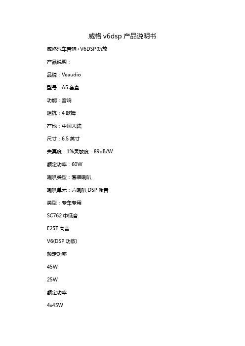
威格v6dsp产品说明书威格汽车音响+V6DSP功放产品说明:品牌:Veaudio型号:A5套盒功能:音响阻抗:4欧姆产地:中国大陆尺寸:6.5英寸失真度:1%灵敏度:89dB/W额定功率:60W喇叭类型:套装喇叭喇叭单元:六喇叭DSP调音类型:专车专用SC762中低音E25T高音V6(DSP功放)额定功率45W25W额定功率4x45W频率范围50Hz-21KHz 1KHZ-21KHz 频率范围20Hz-20KHz 灵敏度90DB90DB信噪比105dB阻抗4040输出阻抗40安装深度60mm14mm工作电压9.5V-16V尺寸6.5寸1付尺寸173x133x47mm31段EQ电脑调音、微信小程序调音、四进六出,USB高清播放、5.0蓝牙传输、手机小程序控制USB选项选曲。
手机小程序控制6种音效、支持USB-wav超高清音质播放。
DSP功放搭载全新高解析力双核芯片处理,无损数字U盘播放器。
1、购买之后,如何安装?可自己手动能安装,也可到洗车美容店或修理店安装。
2、后车门如何搭配?后声场一般选择同轴居多,如果后门有2个喇叭孔位或者可以在门板打孔的话建议选择套装喇叭音效会更佳。
3、需要搭配功放吗?要想音质发挥到醉佳状态,建议安装我们的DSP,或者加装功放,但同比的话DSP效果会更好,因为可以调音,功放仅仅是放大音量而已。
4、安装之后需要调试吗?只是安装喇叭的话不需要调音,如果还加装了功放或者DSP产品建议重新调试一次。
