IND131331软件升级说明
Viavi ONA-1000 100G模块软件更新指南说明书
Viavi OneAdvisor ONA-1000 100G module Software Update InstructionsApril 29, 2020Table of ContentsScope (2)work Upgrade (2)2. USN Upgrade (8)3.StrataSync (12)ScopeThe ONA-1000 platform base software includes software for the 400G module and supported Fiber Optics modules (OTDR, etc.). The 100G module, for the ONA-1000, has its own software and is upgraded separately. This procedure addresses upgrade to the software for the ONA-1000 100G module.NOTE: The ONA 100G module is identified as a MAP-2100 on info and upgrade screens. This is normal. Navigation and upgrades, for the ONA 100G module, are controlled from the 100G module itself. It is important to make sure that you are on 100G module GUI when performing upgrades, regardless of the method chosen. The 100G module GUI is accessed, from the ONA base, by clicking on the 100G icon at top of the screen.To upgrade the ONA-1000 base and 400G module, consult the “OneA dvsior ONA-1000 400G software upgrade procedure”.There are three methods to update ONA-1000 100G module software:work upgrade - Use this method to update your module via an Internet connection.B upgrade - Use this method to update your module with a USB thumb drive.3.StrataSync upgrade - Use this method if your ONA is managed using Viavi’s StrataSync AssetManagement system and you company has elected to deploy software via this method.The ONA must be connected to AC Power, regardless of update method. Please note that network upgrades are NOT supported over WiFi.work UpgradeStep Action Details1.Power On Press and release the power button icon, on the 100G module GUI to poweron the 100G module. NOTE: It is important that you are on the GUI of the100G module and the ONA base. The 100G module is accessed, from thebase ONA GUI, by clicking on the 100G icon at the top of the GUI.2.AC Power Connect the AC power adapter to thepower connector on the right side of the mainframe.N Connection Connect the Ethernet ManagementPort, on the right side of the mainframe,to a network connection with internetaccess, using CAT 5E or better cable.4.System Press the System icon, , at the top of the 100G module screen, todisplay the System Menu. NOTE: It is important that you are on the GUI ofthe 100G module and not the ONA base. The 100G module is accessed, fromthe base ONA GUI, by clicking on the 100G icon at the top of the GUI.work Settings Press the Network icon,, to display LAN Settings. Set IP Mode to“DHCP” for automatic IP address assignment or “Static” for manual input.If using a static address, be sure to configure the DNS server for an accurateaddress or the upgrade will fail to locate the upgrade server. Note: If you areusing static addresses, ensure the IP address is not the same as ONA-1000base IP address.After configuring LAN settings, press the System icon, , to redisplaythe System Menu.6. Upgrade Press the Upgrade icon,, to display upgrade methods.work Upgrade Press to display upgradesettings. Press Reset to Default to ensure the server address name is correct.8.Connect Press to showthe upgrade versions available at .9.Start Upgrade Press , and press to initiate the upgrade.B UpgradeStep Action Details Using an internet browser on your PC or laptop, go to /2.MAP-2100 Click on theto display the MAP-2100 upgrade page.3.Download Click on the icon for the desired server to start the download from that server.There are icons for three servers: EMEA, NORTH AMERICA or APACserver. For example, North America . Click to downloadthe current software revision from that server, if prompted. Do NOT save thedownload directly to the USB stick. Save to your PC and wait for thedownload to complete.B Stick Insert a USB thumb drive into the USB port on your PC or laptop. An 8G orsmaller USB is recommended.5.Extract Open and run the downloaded file, enter the path of the USB stick, and pressto extract files.6.Eject Once the extract has completed, safely eject the USB drive from your PC orLaptop.7.Power on Press the power button on the ONA-1000 100G module to power the moduleon. It is important to ensure that you are on the GUI for the 100G module andnot the ONA base. The 100G is accessed, from the ONA base GUI, byclicking on the 100G icon at the top of the screen.8.AC Power Connect the AC power adapter to the power connector on the right side of theONA-1000 mainframe.B Connect the USB Thumb Drive to the USB port on the 100G module. Note:The USB must be connected to the USB of the 100G module and not theONA-1000 mainframe.10.System Press the System icon, , at the top of the start-up screen, to display theSystem Menu. Note: It is important to make sure you are on the GUI for the100G module. The 100G module GUI is accessed, from the ONA base GUI,by clicking on the 100G icon at the top of the screen.11. Upgrade Press the Upgrade icon,, to display upgrade methods.12.Select USB Press to display upgrade versionsavailable on the USB stick.13.Start Upgrade Press . Press to initiate the upgrade.3.StrataSyncStep Action Details1.Power On Press and hold the ON/OFF button to turn on the 100G module. NOTE: It isimportant to ensure that you are on the GUI for the 100G module. The 100Gmodule GUI is accessed, from the ONA base GUI, by clicking on the 100Gicon at the top of the screen.2.AC Power Connect the AC power adapter to thepower connector on the right side of the ONA-1000.N Connection Connect the Ethernet ManagementPort on the side of ONA-1000to a network connection with internetaccess, using CAT 5E or better cable.4.System Press the System icon, , at the top of the start-up screen, to display theSystem Menu. NOTE: It is important to ensure that you are on the GUI forthe 100G module. The 100G module GUI is accessed, from ONA base GUI,by clicking on the 100G icon at the top of the screen.work Settings Press the Network icon,, to display LAN Settings. Set IP Mode to“DHCP”for automatic IP address assignment or “Static” for manual input.If configuring a static address, be sure to include an accurate DNS address orthe unit will fail to locate the Stratasync server. NOTE: If you are using staticaddresses, ensure that the 100G address is not the same as the ONA base IPaddress.After configuring LAN settings, press the System icon, , to redisplay the System Menu.6.StrataSync Press the StrataSync icon,, to display StrataSync Settings. Ensurethat Account ID and Technician ID match those for your StrataSyncaccount.7.Sync Press to sync your 100G module and initiate upgrades that havebeen assigned by your company’s StrataSync Administrator.Note: When viewing the 100G module, in Stratasync, the asset will appear asa MAP-2100 model. This is normal.。
IND131_331使用说明书
HI331蓝牙HART接口用户手册说明书
HI331 User ManualIntroductionThe HI331 Bluetooth HART Interface is designed to connect PC’s to HART networks via wireless Bluetooth technology. Once the HART side is connected, the user’s application software can then configure, monitor, and document HART based instrumentation from up to 275ft (83.8m) away.System DiagramThe complete system consists of Host PC with Bluetooth transmitter, HI331, and HART network. The Host PC can be a Pocket PC PDA. For PC’s without an integral Bluetooth transmitter, there are many add-on transmitter modules available. SMAR supplies a Class 1 adapter as BT-ADAPTER.Figure 1. Bluetooth System DiagramBluetooth RangeNote that Class 1 Bluetooth transmitters have a range of 275’. Class 2 transmitters have a short r ange of 25’. The HI331 works with both Class 1 and Class 2 transmitters, but operation is limited to the range of the master transmitter.Software DriversNo additional software drivers need to be installed.BatteryThe HI331 contains a Li-Ion rechargeable battery. A fully recharged battery will provide 14 hours of continuous service.Battery ChargingSimply connect the HI331 to your PC USB Port using the supplied USB cable. The yellow “Charge On” LED should illuminate. Note that near a full charge, the “Charge On” LED may blink.Power Switch and LEDPress the power switch to turn on the unit. The green “Power” LED will illuminate when the unit is on. Press the power switch again to turn the unit off. Turn the unit off when not in use to conserve battery life.Battery Charge ErrorWhen the red “Charge Error” LED illuminates, there is a battery charge error condition. This is most likely due to high temperature on the battery. Remove the USB cable from the unit and turn the unit off. Put the unit in a cool location and wait 30 minutes before attempting a recharge. Contact SMAR if the condition persists.Initial PC Setup/ Bluetooth Modem DiscoveryThe following procedure must be done at least once for the PC to “Discover” the HI331.1.Turn on the HI331. It does not need to be connected to the HART network.2.Run the Bluetooth driver software that came with your PC or Bluetooth adapter(ie Linksys). There is typically a Bluetooth icon on the system tray that can bedouble clicked.3.Select “Find Bluetooth Devices” or “Site Survey” to locate any Bluetooth devicesin the area. You could also search for services. Search for “Serial Services” toalso locate Bluetooth devices.4. A device labeled “HART Modem” should be discovered.5.Double click on the “HART Modem” icon. The available serial service willappear as “AMP-SPP”, and say it is not connected.6.Double click on “AMP-SPP”. The Bluetooth connection will be made and theassigned COM port will be reported. Note that if 2 COM ports are reported, usethe “Outgoing” port. Note this port number for your application software.7.Some Bluetooth drivers may prompt for a “Passcode”. Enter “1234”, without thequotes.Discovery needs to be repeated only when adding or changing HI331 modems, or when multiple modems are in the Bluetooth area.Good Practices for PC ApplicationsWe recommend the following steps before use HI331:Install SMAR AssetView StandAlone-Install Smar AssetView StandAlone (or third part Software based on FDT/DTM) that are available in the package;Install DTM for HI331 and Smar Device Library (HART)-Run Setup from HI331 CD/DVD Install (this step will install DTM’s for HI331 and Smar HART Device Library);-After these 2 steps, run Smar AssetView for the first time. Go to the Update Catalogue before start using HI331;PC ApplicationsStart your PC application and set the com port setting to use the com port reported during Discovery. Use the application as normal. The HI331 looks like a normal RS232 device to the application software. The application software does not need to be modified.Multiple HI331 ModemsWhen several modems are in the same area, the Discovery process needs to be repeated. The modems will appear as “HART Modem (1)”, “HART Modem (2)”, etc. It may require trial and error to determine which modem is connected to the desired HART network.HART ConnectionsThe modem can be connected in one of two ways: across the loop load resistor (A – B) or across the HART transmitter terminals (C – D). See Figure 2.Figure 2. HART ConnectionsNOTE: Make the HART connections before turning on the power to the modem. This will improve initial communication reliability.PC Test SoftwareProgram “HM Test” is included on the installation CD to test the operation of the HI331. Launch the program from the CD or from the installed icon. Enter the com port that was assigned to the modem by Windows. Then select “Poll HART Network” to connect to a HART device. The program sends HART Command 0 to determine what transmitters are connected to the loop. The “Status” box will indicate successful operation of theHI331 in your sys tem. Consult the “Troubleshooting” section of this manual if test failure.TroubleshootingProblem:Will not communicateVerify the following:1. Com port number in application is the HI331 com port number.2. Loop power supply is on.3. Loop resistance between 250 ohms and 1Kohms.4. Loop current within HART limits.5. If multi drop configuration, all transmitters in loop have unique addresses.6. HI331 HART connections across loop resistor or across transmitter terminals.7. Battery is charged.8. Modem power switch is on and LED is illuminated.9. Perform the “Discovery” procedure again and verify a connection can be made.10. If using the Linksys USBBT100, verify the Linksys Bluetooth driver is installed and not the Windows Bluetooth driver. There is a known issue with the Linksys install and Windows XP SP2. Go to and search for “USBBT100” for details. Problem:Communications unreliableVerify the following:1. You are in radio range of the master transmitter. For Class 1 devices 275 ft, for Class2 devices, 25 ft.2. Vary the orientation of the master transmitter or the HI331 to improve radio link strength.3. Battery is charged.4. HART connections made before power turned on.5. Transmitter not in Burst mode. Communications can occur in Burst mode, but more retries will be necessary for success.6. In some applications, a connection can be lost, which looks like a communication lock-up. Perform the Discovery process again to reestablish the link without the need to restart your application.Problem:Will not communicate with CornerstonePerform the following:1. In directory “CSCONFIG/DB”, open file “CSLOCAL.INI”.2. Search for “[RDLS2]” without the quotes.3. Change “Debug=0” to “Debug=8”, again without the quotes.4. Save the file.Notice of FCC ComplianceThis product contains a radio module that has been tested and found to comply with the FCC Part15 Rules. These limits are designed to provide reasonable protection against harmful interference in approved installations. This equipment generates, uses, and can radiate radio frequency energy and, if not installed and used in accordance the instructions, may cause harmful interference to radio communications.However, there is no guarantee that interference will not occur in a particular installation. This device complies with part 15 of the FCC Rules. Operation is subject to the following two conditions: (1) This device may not cause harmful interference, and (2) this device must accept any interference received, including interference that may cause undesired operation. Modifications or changes to this equipment not expressly approved by SMAR Ltd may void t he user’s authority to operate this equipment.Contains Transmitter Module FCC ID: X3ZBTMOD1。
关于设备软件升级的操作和注意事项
关于设备软件升级的操作和注意事项关于设备软件升级的操作和注意事项 (1)一、设置IP与添加路由 (2)1、关闭笔记本电脑的无线网络 (2)2、设置IP (2)3、添加路由 (6)二、设备升级后的注意事项 (10)1、关于设备升级后设备序列号的设置。
(10)2、关于选频软件升级为宽带软件后对频段选择的设置。
(12)三、GRRU程序烧录升级 (15)1、打开与设置烧录软件 (15)2、烧录程序 (18)四、调试软件lmt3g使用方法 (23)五、自动选频设置 (25)一、设置IP与添加路由1、关闭笔记本电脑的无线网络设备可以使用网线对近远端进行调试和升级,所以需要对笔记本电脑进行IP设置,并且有些笔记本电脑在打开无线网络的时候不能连接设备,所以首先将无线网络关闭。
2、设置IP设置IP的主要作用是:使电脑用网线连接设备进行调试以及设备软件升级。
注意:设备软件升级需要使用网线方式连接,串口方式连接只能进行调试,不能升级。
2.1、右键单击网上邻居选择属性2.2、弹出网络连接点击“更改适配器设置”2.3、右键单击本地连接选择属性2.4、双击Internet协议版本4(TCP/IPv4)2.5、将本地IP地址设置为10.0.0.123,鼠标单击子网掩码位置自动获取,后单击高级。
2.6、单击添加2.7、将IP地址设置为30.0.0.123,鼠标单击子网掩码位置自动获取,后单击添加。
2.10、点击确定,IP设置完成3、添加路由本路由的添加作用是升级设备程序时,使从近端升级远端程序变为可能,如不添加本路由,则只能在近端或远端本地对设备进行升级。
本路由添加与否对调试设备没有影响。
3.1、开始-运行-输入cmd,后进入DOS界面3.2、输入route ADD -p 20.0.0.0 MASK 255.0.0.0 10.0.0.254注意区分大小写输入route ADD -p 20.0.0.0 MASK 255.0.0.0 30.0.0.254注意区分大小写完成二、设备升级后的注意事项1、关于设备升级后设备序列号的设置。
[VIP专享]华为设备软件升级功能实现说明
![[VIP专享]华为设备软件升级功能实现说明](https://img.taocdn.com/s3/m/f2ef5d1083d049649a665896.png)
0% 0%
0
0
GigabitEthernet1/0/0
*down down
0% 0%
0
0
GigabitEthernet1/0/1
*down down
0% 0%
0
0
GigabitEthernet1/0/2
*down down
0% 0%
0
0
GigabitEthernet1/0/3
*down down
0% 0%
*down: administratively down
^down: standby
(l): loopback
(s): spoofing
(b): BFD down
(d): Dampening Suppressed
InUti/OutUti: input utility/output utility
Interface
up
--
0.06% 0.05%
0
up
--
0.05% 0.03%
0
up
--
0.03% 0.01%
0
up
--
0.01% 0.01%
Hale Waihona Puke 0up--
0.05% 0.09%
0
up
--
0.01% 0.01%
2
up
--
0.01% 0.01%
0
up
--
0% 0.01%
0
up
--
0% 0.01%
0
up
--
1 CE 设备软件升级
1.1
升级前设备状态检查备份与 ping 测试.
状态检查与备份
深圳市英贝德 单板机产品软件升级技术 说明书
英贝德科技嵌入式系统解决方案单板机产品软件升级技术说明书(Win CE篇)V1.02版本信息:版本日期备注V1.00 2008-03-06 完成说明书第一版制作V1.01 2008-03-13 修改升级流程图和强制功能说明V1.02 2008-04-16 修改部分细节说明不详之处1.前言 (3)2.升级原理介绍 (3)2.1基本原理 (3)2.2生成文件流程图 (3)2.3升级流程图 (4)3.配置文件生成软件介绍(EBDSerialID.exe) (5)3.1技术特征 (5)3.2 EBDSerialID.exe软件界面 (5)3.3字段功能说明 (6)3.4细则 (7)4. 升级监控程序介绍(EBDUpdate.exe) (9)4.1 技术特征 (9)4.2 升级流程图 (9)4.3细则 (10)单板机产品软件升级解决方案是英贝德科技嵌入式系统解决方案旗下的方案之一,是解决嵌入式系统设备“在应用编程(IAP)”的优秀方案。
它可以轻松实现使用SD卡、CF卡、U盘等热插拔存储设备对操作系统和应用软件的在系统升级。
这可以大大节省系统维护成本、提高系统工作效率。
适用于工控、医疗、监控、数据采集等各类嵌入式系统设备的升级更新。
《单板机产品软件升级技术说明书(Win CE篇)》主要介绍Win CE操作系统和应用软件升级方案的技术性内容,帮助技术人员了解此方案的工作原理和技术特性。
关于软件升级的操作方法请参见《单板机产品软件升级操作手册(Win CE 篇)》。
如有疑问请与英贝德科技技术支持部联系。
2.升级原理介绍2.1基本原理在Win CE操作系统内部已经集成了内核升级监控程序EBDUpdate.exe,并在系统运行期间一直处于监控状态。
当有可热插拔存储设备(如U盘、SD卡、CF卡等)插入时,监控程序会自动检测存储设备中是否满足升级条件,并做相应的处理。
即根据存储设备内的配置文件、内核校验文件以及用户的选择,判断是否升级当前系统,若确认升级,则将内核文件和配置文件中的数据写到Flash中,完成系统升级。
SS-331 LCD Desoldering Station用户手册说明书
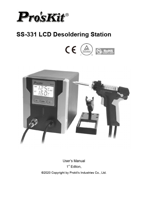
SS-331 LCD Desoldering StationUser’s Manual1st Edtion,©2020 Copyright by Prokit’s Industries Co., Ltd.DescriptionSS-331 designed for lead free desoldering especially. The quick heating and strong power are for convenient and clear soldering / desoldering all types of DIP components.Reasonable structure, single hand operation and strong absorbing power can be easy removal of the residual solder from the one-sided or two sided of the PCB. This tool is used in the fields of electronic research, teaching and production, especially in the repairing and desoldering on the electronic appliances and communication equipments.1. Control UnitThe desoldering iron gun is controlled automatically by the micro-processor. The digital control electronics and high-quality sensor and heat exchange system guarantee precise temperature control at the soldering tip. The highest degree of temperature precision and optimal dynamic thermal behavior under load conditions is obtained by the quick and accurate recording of the measured values in a closed control circuit, and this design is especially for the lead-free production techniques.2. Desoldering Iron gun (5SS-331N-DG)Desoldering iron gun with a power of 90W and a wide spectrum of soldering tips can be used anywhere in the electronics field.The high power and gun type design make this iron gun suitable for fine desoldering work. The heating element is made of ceramic and the sensor on the desoldering tip can control the desoldering temperature quickly and accurately.Technical SpecificationModel No. SS-331B SS-331H SS-331E Voltage 220V-240V~ 50Hz 120V~ 60Hz Soldering Power 90WPower Consumption 140WTemperature 160°C ~ 480°CVacuum Pressure >600mm HgHeating Element Ceramic HeaterSleep mode Approximately 10 minutes if not useAccessories Spare tip x 3 (∅ 1.2(on the gun)∅1.0/ ∅ 1.5mm) Cleaning tool x 3 (∅0.7/∅0.9/∅ 1.2mm)Filter sponge x 4 (φ20.8x1 +φ16.8x3)Certificate CE, RoHS RoHS cTUVus, RoHS PlugStation Size (mm) 172 x 135 x 190Weight (kgs) 1.6Operating Instruction1. Place the desoldering iron gun in the holder separately. Then connect the plugto the receptacle on the station and turn clockwise to tighten the plug nut. Check that the power supply is corresponding to the specification on the type plate and the power switch is on the “OFF” position. Connect the control unit to the power supply and switch on the power. Then a self-test is carried out in which all display elements are switched on briefly. The electronic system then switches on automatically to the set temperature and displays this value.2. If not use for about 10 minutes ,the desolering station will be automatically intosleeping mode and the temperature is reduced to 200 C, this for prolonged the life of the suction nozzle and the heating element; Shake or pick up the desoldering Iron gun, can start the working again.3. The display and temperature setting①.Shows the actual temperature of the desoldering tip.②.Shows the setting temperature: Pressing the “UP” or “DOWN” button canswitch the digital display to the set point display. The set-point can bechanged for ±1℃by tapping the “UP” or “DOWN” button. Pressing thebutton will change the set-point quickly. The digital display will returnautomatically to the actual value and the iron will reach to the settingtemperature quickly.③.℃/℉display: Switching the temperature display from ℃to ℉bypressing the “ *”button and then the electronic system will display theactual temperature①and setting temperature②in ℉, and vice versa.④.When the actual temperature on the desoldering tip is less than theset-point, “HEAT ON” will display and make the desoldering tip heatingup.⑤.When the absolute offset is more than ±10℃between the actualtemperature and the set-point on the desoldering tip or the nozzle,“WAIT” will display. It means that the temperature electronic controlsystem is not in the stable situation, we should wait a moment to let the“WAIT” disappear.⑥.When “-----” & “ERROR” display, there may be a trouble on the system,or the desoldering iron gun is not connected to the control systemcorrectly.Safety Instruction1. The manufacturer assumes no liability for uses other than those described inthe operating instructions or for unauthorized alterations.2. The operating instructions and cautions should be read carefully and kept in aneasily visible location in the vicinity of the control system. Non-observance of the cautions will result in accidents, injury or risks to health.Caution1. The power cord only can be inserted in approved power sockets or adapters.2. High TemperatureWhe temperature of the desoldering tip will reach as high as around 400℃(752℉)When the power switch is on. Since mishandling may lead to burns and fire, be sure to comply with the following precautions:A. Do not touch metallic parts near the desoldering tip/ nozzle.B. Do not use this system near the flammable items.C. Advise other people in the work area that the unit can reach a very hightemperature and should be considered potentially dangerous.D. Turn off the power switch while taking breaks and when finishing using.E. Before replacing parts or storing the system, turn off the power and let itcool down to the room temperature.F. Warning: this tool must be placed on its stand when not in use.G. A fire may result if the appliance is not used with care, therefore:a) Be careful when using the appliance in places where there iscombustible material.b) Do not apply to the same place for a long time.c) Do not use in presence of an explosive atmosphere.d) Be aware heat may be conducted to combustible materials that outof sight.e) Place the appliance on its stand after use and allow it to cool downbefore storage.f) Do not leave the appliance unattended when it is switched on.3. Take care of your toolsDo not use the tools for any applications other than desoldering.Do not rap the iron against the work bench or otherwise subject the iron to severe shocks.Do not file the desoldering tip to remove the oxide, please wipe the tip on the cleaning sponge.Use only accessories or attachments which are listed in the operation manual.Use of other tools and other accessories can lead to a danger of injury.Please turn off the power before connecting or disconnecting the desoldering iron gun.4. Maintenance4.1 Before further use, safety devices or slightly damaged parts must becarefully checked for error-free and intended operation.4.2 Inspect moving parts for error-f ree operation and that they don’t bind, orwhether any parts are damaged.4.3 Damaged safety devices and parts must be repaired or replaced by aqualified technician, so long as nothing else is indicated in the operation manual.4.4 Use only accessories or attachments which are listed in the operationmanual. Use of other tools and other accessories can lead to a danger of injury.5. Keep children at a distanceWarning: this appliance is not intended for use by young children andinfirm persons unless they have been adequately supervised by aresponsible person to ensure that they can use the appliance safely.Warning: Young children should be supervised to ensure that they do not playwith the appliance.Unused desoldering station should be stored in a dry location which is out of thereach of children. Switch off all unused desoldering station.6. Protect yourself against electrical shocksAvoid touching grounded parts with your body, e.g. pipes, heating radiators andso on. The grip of antistatic designed desoldering tool is conductive.7. Work environmentDo not use the desoldering station in a moist or wet environment. Thedesoldering iron gun should be placed on the holder after finished using.8. Observe the valid safety regulations at your work place.Desoldering Gun MaintenancePush the knob up, and then pull theback holder.WARNINGS:1. To avoid injury or damage the items, do not touch the metallic parts near thenozzle, and do not use this system near the flammable items.2. Remove the power plug before performing maintenance procedure, exceptdoing the nozzle and heating element clean process.3. If the pump does not operate, immediately clean the nozzle & heating element,and replace the filter4.In the high temperature, the solder waste will get oxidized(lead free solder’s melting point is 220° C, non-lead fr ee solder’s melting point is 180° C),swelled and stuck on the inner wall tightly, If it did not clean after use, the solder wastewill block the desoldering gun, can not remove even use cleaning pin.( Cleaning pin)Please follow below steps to remove the solder waste: 1.Push the knob up, and then pull the back holder.2. Take the spring out from the glass tube ,then remove the solder wastePut the spring back to glass tube, then put glass tube back to position.Press the back holder, then the knob will bullet down and become locked automatically .INSTRUCTIONS: 1. After each operation is finished, please idling suck the desoldering gun3-5 times soon, this can clean the solder waste inside the pipe.2. If the operation interval is about 20 minutes, after idling sucking the desoldering gun, please also use the cleaning tool to clean the pipe.3. When you find the desoldering efficiency gets down, please use the cleaning Pin to clean the pipe immediately.4. If the operation interval is long, we advise to adjust the temperature to about 200° C . When you use it again, you can adjust to the working temperature,5.When the glass tube has absorbed about 1/2 solder waste, please clean it immediately. When you find the filter is getting hardened, please replace the filter immediately.Aluminum pieceGlass tubeFilterTroubleshootingFault phenomenon Failure cause solutionLCD No display Fail to connect powersource Check the power cord connection and plug in the power cord to power Jack.Fuse blown Replace fuse : 3.15A / 250VFail to Set temperature Key damage Return to dealerSuction non-action Trigger switch damage Return to dealerMotor damage Return to dealerNozzle is not hot Heating elementdamagedReturn to dealerinternal wire damage Return to dealerCan not melt solder Unreasonable setting oftemperatureReset the appropriate temperaturenozzle oxidation Replace nozzlenozzle is not hot Return to dealerSuction ability is low Blow- by Check the connection of vacuum outletCheck the installation of glass tubeExcessive solder waste storage in glass tube Removing solder waste from glass tubeFilter degradation Replacement of filter Air pump bad Return to dealerUnable to absorb solder solder hole blocked under heating condition, using cleaningpin to clean heating elementSolder meltinadequatelywhen solder is completely meltedTin absorption hole blocked, can not be dredged Solder wasteaccumulate at the end ofheating elementTake off the glass tube, use thesoldering iron to heat the steel pipeback to remove the solder waste, andthen use the cleaning pin to dredge.NutChecking the heating element:Disconnect the plug and measure the resistance value between the desoldering gunconnecting plug pins as follows.If the resistance values of 'a' and 'b' are outside the above value, replace the heating element (sensor).If the resistance values of 'd' is outside the above value ,Sleep mode was lose efficacyReplace the heating element:1)Disconnect the power plug, wait unit the desoldering gun temperature down to room temperature.2)Loosen screws and disassemble desoldering gun.3)Cut off the wire of heating element, prepare a new heating element (model no. 5SS-331N-H).as follow figure.4)Connect heating element :Put the heating element on the black heating element holder, insert the heat shrink tube (Φ3x25mm )and metal tube (Φ2x6mm) to the wire, connect wire and pull the metal tube to the connect position, crimping the metal tube with crimper tool, pull the heat shrink tub to the metal tube and heating.-- Long blue wire (ground) connects to the yellow wire in handle-- Two white wires (heating element) connect to the two red wire, no need to distinguish positive electrode and negative electrode.-- Two blue wires (Sensor) connect to the black and blue wire in handle, no need to distinguish positive electrode and negative electrode. -- Any one wire connect to the Sleep control sensor5)Measure the resistance value again, make sure the value is correct. Short the desoldering gun nozzle and shell of plug, and the resistance value should be 0Ω. 6)Assembly desoldering gun again, do not press the wire or put into the wrong position.Note : The color of wire for reference, color change without notice.Any repair or replacement operation by professional operatora. Between pins 1 & 2 (Sensor)50Ω±3Ω(25℃ room temperature) b. Between pins 3 & 4 (Heating Element) 2Ω±1Ω(25℃ room temperature) c. Between pin 5 & 6 0Ω (tigger on)d. Between pin 7 & 2open or 0Ω(shaking gun)SS-331数显吸焊台使用手册警告!为降低伤害风险,用户必须阅读使用手册概述SS-331 特别为无铅吸焊而设计。
博斯奇ESI[卡车]重型卡车软件更新指南说明书
![博斯奇ESI[卡车]重型卡车软件更新指南说明书](https://img.taocdn.com/s3/m/c053cd28c950ad02de80d4d8d15abe23492f0304.png)
Bosch ESI[truck] Heavy Duty Truck Software Update – Q2 2019Ver 2019/2full of valuable and timesaving coverage features thatyou don’t want to miss. Included are the details onnew coverage additions.In addition, the new Off-Highway Software package isnow available, which gives users the ability todiagnose construction and agricultural vehicles.Update your Bosch ESI[truck] Diagnostic Scan Tool tosoftware version 2019/2 today to maximize thepower of your Bosch ESI[truck] Diagnostic Scan Tool.Newly Available Software FeatureOff-Highway Software∙Off-Highway coverage was first available with revision 2018/3∙Includes diagnostic coverage for construction, agricultural, stationary engines, street sweepers, and more∙NOTE – these features are only available if you have purchased the ESI[truck] Off-Highway Upgrade Cable Kit and Introductory Software. Learn more about Bosch Off-HighwaySoftware at https:///pro/products/esitruck-highway-upgrade-cable-kit-introductory-software-licenseSoftware UpdatesNew Category Filter∙In the vehicle identification process, users can now filter by selecting a vehicle category. This makes the process easier in cases where different types of vehicle make and model exist. Firmware Update Improvements∙The firmware update process has been improved, and is faster and even more reliable than before.Added Coverage - SummaryCoverage MetricsUpdates since last software revision:∙9 New Makes∙366 New Models∙1,653 New Electronic Control Systems∙1,496 New Wiring Diagrams∙14,692 New Fault Codes∙3,148 New Troubleshooting by Trouble Code ProceduresHeavy –Duty Truck Additional CoverageNew content has been added for the following Heavy Duty Brands:∙Allison∙Bendix∙Caterpillar∙Cummins∙Detroit Diesel / MBE∙Eaton∙Freightliner∙Mack∙Meritor Wabco∙Navistar∙Paccar∙PSI∙VolvoTrailer Additional CoverageNew content has been added for the following Trailer Brands:∙Meritor Wabco∙VigiaLight and Medium –Duty Truck Additional CoverageNew content has been added in the following Light and Medium-Duty (Light Commercial Vehicles) Brands:∙Dodge∙Ford∙GMC/Chevrolet∙Isuzu∙Mercedes BenzOff-Highway: Agricultural Vehicles Additional CoverageNew content has been added in the following Agricultural Vehicle brands:∙ISOBUS (ISO 11783) for all compatible tractors∙Claas∙Case iH∙Deutz Engines∙Deutz-Fahr∙Fendt∙John Deere∙Lamborghini∙Lindner∙Massey Ferguson∙New Holland∙SameOff-Highway: Construction Vehicles Additional CoverageNew content has been added in the following Construction and Off-Highway Vehicle brands:∙All models with ZF Ergopower EST-37 transmissions∙Bobcat∙Case CE∙Caterpillar∙Hidromek (new brand covered)∙Hitachi∙JCB∙JLG (new brand covered)∙John Deere∙Kramer∙Manitou∙Volvo CE∙Yanmar (new brand covered)∙ZF TransmissionsOff-Highway: Stationary Engines Additional CoverageNew content has been added in the following Stationary Engine brands:∙Deutz∙Hino∙VM Motori∙Volvo PentaOff-Highway: Street Sweeper Additional CoverageNew content has been added in the following Street Sweeper brands:∙Hako (new brand covered)∙Johnston (new brand covered)1.NEW SOFTWARE FUNCTIONALITIES (7)2.NEW FUNCTIONALITIES BY BRAND IN HEAVY DUTY TRUCK AND BUS (8)2.1.ALLISON (8)2.2.BENDIX (8)2.3.CATERPILLAR (9)2.4.CUMMINS (10)2.5.DETROIT-DIESEL (12)2.6.EATON (12)2.7.FREIGHTLINER (13)2.8.MACK (13)2.9.MERITOR WABCO (14)2.10.NAVISTAR (14)2.11.PACCAR (16)2.12.PSI (17)2.13.VOLVO (17)3.NEW FUNCTIONALITIES BY BRAND IN TRAILER (19)3.1.MERITOR WABCO (19)3.2.VIGIA (19)4.NEW FUNCTIONALITIES BY BRAND IN LIGHT COMMERCIAL VEHICLES (LCV) (20)4.1.DODGE (20)4.2.FORD (20)4.3.GMC/CHEVROLET (21)4.4.ISUZU (22)4.5.MERCEDES-BENZ (23)5.NEW FUNCTIONALITIES BY BRAND IN OFF-HIGHWAY AGRICULTURAL VEHICLES (24)5.1.ISOBUS(11783) (24)5.2.CLAAS (24)5.3.CASE I H (25)5.4.DEUTZ E NGINES (25)5.5.DEUTZ-FAHR (25)5.6.FENDT (26)5.7.JOHN DEERE (26)MBORGHINI (26)5.9.LINDNER (26)5.10.NEW HOLLAND (27)5.11.MASSEY FERGUSON (27)5.12.SAME (27)6.NEW FUNCTIONALITIES BY BRAND IN OFF-HIGHWAY CONSTRUCTION VEHICLES (28)6.1.BOBCAT (28)6.2.CASE CE (28)6.3.CATERPILLAR (28)6.4.HIDROMEK (29)6.5.HITACHI (29)6.6.JCB (29)6.7.JLG (29)6.8.JOHN DEERE (29)6.9.KRAMER (30)6.10.MANITOU (30)6.11.YANMAR (30)6.12.VOLVO CE (30)7.NEW FUNCTIONALITIES BY BRAND IN OFF-HIGHWAY STATIONARY ENGINES (31)7.1.DEUTZ (31)7.2.HINO (31)7.3.VM MOTORI (31)7.4.VOLVO PENTA (31)8.NEW FUNCTIONALITIES BY BRAND IN OFF-HIGHWAY STREET SWEEPERS (32)8.1.HAKO (32)8.2.JOHNSTON (32)1. NEW SOFTWARE FUNCTIONALITIES New filter by Category in the model selectionIn the vehicle identification process, users can filter by selecting a vehicle category. This makes the process easier in cases where different types of vehicle make and model exist. Example of cereal harvester and tractor shown above.This filter will not show up if there are no categories to choose from.Firmware updateThe firmware update process has been improved, and is faster and even more reliable than before.2. NEW FUNCTIONALITIES BY BRAND IN HEAVY DUTY TRUCK AND BUS2.1. ALLISONMore intuitive hydraulic diagrams.3000/4000 5th Gen, Power take-off parameter adjustment. Gear shift learning and calibration.TC10 5th Gen, maintenance services.2.2. BENDIXWingman Advanced, FLR21, Radar alignment.2.3. CATERPILLARParametersTire size modification and vehicle speed sensor.Engine protection in low gears.Power take-off.EPA07 engines, maintenance services.2.4. CUMMINSImprovement of the error deletion and the MIL lamp switching off. Engines from EPA04 onwardsAdditional information to fault codes.Engines from EPA07 onwardsEngine data and operation reset.B 4.5/6.7 CM2350Status check of the DPF particulate filter.X15 CM2350Password management. Engine types and maintenance services. ISG 10.5/11.8 CM2880AdBlue/DEF leak test.ISL 8.9/9.5 CM2150 SN (Euro 4.5 - 5)Development of parameters such as VIN, tire size, PTO. Maintenance service parameters.ISM CM875Reset of maintenance services.Parameters: engine brake, vehicle speed source, engine protection. ISF 2.8/3.8/4.5 CM2220NOx data reset.ISL8.9 CM850Reset of maintenance services.Parameters: engine brake, vehicle speed source, engine protection. ISB CM850Parameters: engine brake, power take-off (PTO).ISBe (4 & 6 cylinders) CM800 (ECS-DC3)Parameters, vehicle speed source.QSF 3.8 CM2350Intake air heater.SAE J1939 data link control.Aftertreatment data record.AdBlue/DEF checks.QSB 4.5/6.7 CM2350 B105/B106/B112Compatibility of the VGT (Variable Geometric Turbine) actuator. Aftertreatment data record.Parameters, fan control.QSB3.3 CM2150/CM2250Parameters, idle speed.2.5. DETROIT-DIESELDDEC 16 DD8New coverage.DDEC VI Series 60Engine types.CPC3Evo (New Cascadia).Modification of parameters such as the cruise control, power take-off and engine protection. CPC4 (New Cascadia)Automatic shutdown at idle.DT12Replacement of the TCM control unit.2.6. EATONTCM Gen3 and TCM EndurantPTO parameters and maintenance services.2.7. FREIGHTLINERNew steering angle control system, SAS01T.2.8. MACKUS17 enginesEngine types and maintenance services.EMS V3Parameters: speed limit, cruise control and idle revolutions. Exhaust gas recirculation test, injector coding for new variants, aftertreatment data record.2.9. MERITOR WABCOTractor ABSTire size modification.SmartTrac HABSNew system.2.10. NAVISTARA26 engineInjector coding, DPF Reset and parameters such as maximum speed, among others. Maintenance services and engine types.DLC enginesParameters: engine brake configuration, power take-off (PTO) and vehicle speed signal (tire size).MaxxForce enginesParameters: vehicle speed signal (tire size).N SCR enginesEngine brake parameters.2.11. PACCARTroubleshooting guides for fault codes.GHG17 enginesMaintenance services and engine types.PCI KWP2000Injector coding, configuration of the idle speed, the speed limit and the cruise control for new variants. Engine brake test.Disabling of the power reduction caused by EGR and AdBlue/DEF failures.2.12. PSINew 8.8 gasoline system, technical information, wiring diagram.2.13. VOLVOUS17 enginesMaintenance services and engine types.EMS V3Parameters: speed limit, cruise control and idle revolutions. Exhaust gas recirculation test, injector coding for new variants, aftertreatment data record.TRAILER3.1. MERITOR WABCOTrailer ABS 2M with RSS PlusControl unit replacement.System Display.3.2. VIGIANew systems (only with technical information) with wiring diagrams and tire pressure calibration procedures.LIGHT COMMERCIAL VEHICLES (LCV) 4.1. DODGERam 2500-5500 with Cummins 6.7 engine [2013-2017]Coverage in the engine management system (DPF reset, activations) and wiring diagrams.New ABS brake systems and IPC instrumentation.4.2. FORDF-250-550 6.7 PowerStroke 2017 & 2018Parameter: maximum vehicle speed, reset of the DPF differential pressure sensor and IVD reset (ABS).F-250-550 6.8 GasCylinders balance and vehicle data learning.F-250-550 6.2 GasABS activations and IVD (Interactive Vehicle Dynamics) reset. Transit 3,2 DieselVehicle data learning and IVD (Interactive Vehicle Dynamics) reset.4.3. GMC/CHEVROLETSierra/SilveradoEBCM brake system, component activation.L83 5.3 & L18 8.1, V8 enginesNew system with functions such as oil maintenance, reset of idle values and fuel injection (Fuel Trim), besides the reset of the O2/Lambda sensor.LLY (6.6 Duramax) VPW enginesEngine protection parameters.4.4. ISUZUTCM Smoother K Line transmission – Option B in the N-Series/F-Series modelsNew parameters, such as settings of the power take-off, gear ratio and tire size.6HK1-TC (K Line) engineRegeneration and reset of the DPF particulate filter.4.5. MERCEDES-BENZ CDID3Fuel pump activation.5. NEW FUNCTIONALITIES BY BRAND IN OFF-HIGHWAY AGRICULTURAL VEHICLES5.1. ISOBUS (11783)New functionality test.5.2. CLAASLexion modelsProgramming and calibration of the product yield sensors, installation of a new sensor and reset of a sensor acquired as spare part. Wiring diagram configurations for the EHS, SAM, OPM, ATP and YMM systems in Lexion and Tucano Series harvester models, as well as the OPM, ATP and SBM systems in Jaguar Series models.Ares, Atles, Arion and Axion modelsMaintenance reset.5.3. CASE iHNew models, Case iH Optum Final Tier 4, Case iH Luxxum, Case iH Magnum (180, 200, 220, 240) Final Tier 4.New regulation interface system of the ENG motor for the models Steiger, Puma, MXU, Maxxum, Magnum and Axial-Flow.5.4. DEUTZ EnginesEMR4 engine management systems, service regeneration for CRT models in the EDC 17 CV52 system; injector coding, reset of the rail pressure regulation valve and much more in the EDC 17 CV54 system.5.5. DEUTZ-FAHRNew harvester models that include advanced diagnosis operations and wiring diagram configurations in different systems such as the rear lift, instrumentation, armrest, etc.5, 6 and 7 Series models; Agrotron, Agrofarm, calibrations and manual diagnosis.5.6. FENDTDeutz and MAN engineType technical data associated to the Vario Series, Farmer and Favorit models.5.7. JOHN DEERENew harvester models. 6030 Series, 7020 Series and 7030 Series models, vehicle configuration parameters.New SCC spool valve control panel in 6R models. Increase of technical data related to air conditioning, 34 updated engine types in the section “Liquid capacity and quality”.5.8. LAMBORGHININitro, R3, R4, R6, R7 and R8 models, calibrations and manual diagnosis in multiple systems such as the rear lift, front suspension, power take-off, transmission.5.9. LINDNERRestructuring of the brand, 16 new models.5.10. NEW HOLLANDNew models T7 AC – CVT Series Final Tier 4.Interim and Final Tier 4 models, maintenance reset.Engine management and exhaust aftertreatment system EDC 17 CV41 + Denox 2.2, NOx sensor reset, reset of the rail pressure regulation valve, etc.5.11. MASSEY FERGUSONX700 Series modelsVehicle configuration parameters.X400 Series modelMaintenance services.EEM4F-EDC 17 CV41 Final Tier 4Engine management system, catalyst cleaning.5.12. SAMEFortis, Iron, Diamond, Virtus and Explorer modelsCalibrations and manual diagnosis.6. NEW FUNCTIONALITIES BY BRAND IN OFF-HIGHWAY CONSTRUCTION VEHICLESIt should be noted that the technical information has been extended in all models with ZF Ergopower EST-37 transmissions (WG110-WG311 transmissions), with wiring diagram configurations. Their coverage has also been increased with new actuations and checks for all the models of the project.6.1. BOBCATRestructuring of the brand.New connector JDC 539A.6.2. CASE CEWiring diagram configurations for ZF Ergopower transmissions. It is worth noting that the coverage of the ZF Ergopower EST-37 system (WG110-WG311 transmissions) has been increased with new actuations and checks for all the models of the project.6.3. CATERPILLARNew exhaust gases treatment system ARD (Aftertreatment Regeneration Device).New SAE J1939 engine management systems, engines C-3.3B, C-3.8 and C-15, which include advanced diagnosis.6.4. HIDROMEKNew brand.6.5. HITACHINew MON Monitor Controller for Series 5 and 6 excavators.6.6. JCBThe manual diagnosis has been extended for the 500 Series model (Tier 3 /Stage IIIA).New systems in compact excavators.Reset of the emergency stop indicator and calibration of the boom angle sensor for the hydraulic system in telescopic handlers.6.7. JLGNew brand.6.8. JOHN DEERENew systems in bulldozers and wheel loaders. The TCU transmission system can be highlighted. It includes advanced diagnosis functionalities, such as the clutch calibration.Wiring diagram configurations for the engine management system and hydraulic systems in K Series models.6.9. KRAMERRestructuring of the brand, 12 new models.6.10. MANITOURestructuring of the brand, 11 new models.New LSL1 and LSL2 hydraulic systems, with technical releases and procedures to check and calibrate the load limitation of the telescopic arm.6.11. YANMARNew brand.New connector JDC 538A.6.12. VOLVO CERestructuring of the brand, which includes 18 families and 45 models.New MECU system, which includes the calibration of the transmission in articulated haulers. Hydraulic systems in excavators, new checks and actuations.OFF-HIGHWAY STATIONARY ENGINES 7.1. DEUTZEMR4 engine management systems, service regeneration for CRT models in the EDC 17 CV52 system; injector coding, reset of the rail pressure regulation valve and much more in the EDC 17 CV54 system.7.2. HINONew brand available in stationary engines, with advanced diagnosis, wiring diagrams, troubleshooting guides, etc.7.3. VM MOTORIEDC VM R754TE4/ISE4 engine management system, actuations, checks, parameter settings, particulate filter regeneration. This system is included in multiple STREET SWEEPER models.7.4. VOLVO PENTAWiring diagram configurations for engine management systems with V2 technology.OFF-HIGHWAY STREET SWEEPERS 8.1. HAKONew brand.8.2. JOHNSTONNew brand.Visit for more information on ESI[truck].Bosch Automotive Service Solutions Inc.28635 Mound RoadWarren, MI 48092USA*************************855-267-2483。
梅特勒托利多IND131-331称重显示控制器使用说明书(1)

梅特勒托利多IND131-331称重显示控制器使用说明书(1)附录E树形菜单结构图参数设定表F1F2F3F4F5CommunicationScale秤台Application应用Terminal仪表通讯Maintenance维护gF1.1F2.1F3.1F4.1F5.1TargetOperationOutputTemplateScaleDiagnosticsType类型预置点设置SerialNumber序列号秤的诊断输出模板F1.1.1F2.1.1F3.1.1F4.1.1F5.1.1ToleranceTypeSerialNumberLoadCellOutputName名称允差类型序列号Format格式传感器输出.F1.1.2F2.1.2F3.2F4.1.2F5.1.2OutputTypeScreenSaverPrintScaleNameCalibrationValuesApproval认证输出类型屏保打印秤名称标定值F1.2F2.1.3F3.2.1F4.2F5.1.2.1Capacity&Increment量程与分度值TargetSource目标值数据源ScreenSaverConnections通讯接口连接ZeroCounts屏保零点内码F1.2.1F2.1.4F3.3F4.2.1F5.1.2.2Units单位TargetLatching目标值锁存Region区域COM1Assignment串口1应用TestLoad1砝码1值3F1.2.2F2.2F3.3.1F4.2.1.1F5.1.2.3TestLoad1CountsCapacity量程TargetValues预置点MenuLanguage快捷操作菜COM1Checksum校验和砝码1内码F4.2.2F1.2.3F2.2.1F3.3.2F5.1.2.4单语言COM2AssignmentIncrement分度值T argetSetupLanguage设置菜单语言串口2应用TestLoad2砝码2值目标值F1.2.4F2.2.2F3.4F4.2.2.1F5.1.2.5COM2ChecksumTestLoad2Counts×10Always10倍扩展-TolUser用户校验和砝码2内码负允差F1.3F2.2.3F3.4.1F4.3F5.1.3PasswordProtectionCalibration标定+T ol正允差密码保护Serial串口Statistics统计F1.3.1F2.2.4F3.4.2F4.3.1F5.1.3.1LinearityPasswordCOM1Weightments线性Spill提前量密码串口1称重次数F1.3.2F2.2.5F3.5F4.3.1.1F5.1.3.2SetZero标定零点MenuKeys快捷操作菜单BaudRate波特率Overloads过载次数FineFeed细喂料F1.3.3F2.3F3.5.1F4.3.1.2F5.1.3.3SetSpan标定量程ComparatorsCalibrationAccess访问标定DataBits数据位Peakweight最大称重比较器F1.3.4F2.3.1F3.5.2F4.3.1.3F5.1.3.4逐步替代法标定Comparator1Source比较器1数据源ZeroCommandsStepCalTargetAccess访问目标值Parity奇偶校验清零指令F1.3.5F2.3.2F3.5.3F4.3.2F5.1.3.5Comparator1ActiveComparatorAccessZeroFailures CalFREE免标定比较器1算子访问比较器COM2串口2清零失败COM2/F1.4F2.3.3F3.6F4.3.2.1F5.2ZeroResetBaudRateSerialTest清零Limit1下限1复位并行波特率串口测试F1.4.1F2.3.4F4.3.2.2F5.2.1输入AutoZero自动清零HighLimit1DataBits数据位COM1串口1 上限1输出F1.4.2F2.3.5F4.3.2.3F5.2.2DeviceNetAutoZeroRangeComparator2Source自动清零范围比较器2数据源选件Parity奇偶校验COM2串口2 F1.4.3F2.3.6F4.3.2.4F5.3选件PowerUpModeComparator2ActiveDiscreteI/OTest开机模式比较器2条件Interface接口输入输出(DIO)测试F1.4.4F2.3.7F4.4F5.4DisplayTest显示屏测试式UnderZeroBlanking欠载范围Limit2下限2PLCPLC7F5.5F1.4.5F2.3.8F4.4.0SoftwareUpdate软件升级PowerUpZeroF1开机清零HighLimit2上限2PLCTypePLC类型F5.6F1.4.6F2.3.9F4.4.1Reset复位PushbuttonZero按键清零Comparator3Source比较器3数据源AnalogOutput模拟量输出F2.3.10F4.4.1.1F1.5Comparator3Active比较器2条件Source数据源Tare去皮F2.3.11F4.4.1.2模拟量输出选件F1.5.1ZeroValues零点值Limit3下限3PushbuttonTare按键去皮F2.3.12F4.4.1.3F1.5.2FullSpanValueHighLimit3上限3满量程值NetSignCorrection负净重修正F2.4F4.4.1.4F1.6CalibrationOutputDiscreteI/O输入输出(DIO)标定输出Rate流量F2.4.1F4.4.1F1.6.1DiscreteInputsA-BRIOA-BRIO输入(IO)WeightUnits重量单位F2.4.1.1F4.4.1.5F1.6.2Input1PolarityNodeAddress节点地址输入1极性TimeUnits时间单位F2.4.1.2F4.4.1.6F1.6.3Input1Assignment输入1应用StartQuarter起始组MeasurementPeriod测量时间F2.4.1.3F4.4.1.7F1.6.4Input2Polarity输入2极性LastRack终结机架OutputAverage输出平均值A-BRIO选件F2.4.1.4F4.4.1.8F1.7Input2Assignment输入2应用DataRate数据传输速率Filter滤波F2.4.2F4.4.2F1.7.1 DiscreteOutputsDataFormat输出(DO)数据格式LowPassFilter低通滤波F2.4.2.1F4.4.2.1F1.7.2Output1AssignmentFormat格式输出1应用StabilityFilter稳态滤波F2.4.2.2F4.4.2.2F1.8Output2AssignmentByteOrder字节顺序输出2应用Stability稳态F2.4.2.3F4.4.1F1.8.1Output3Assignment输出3应用PROFIBUSPROFIBUSPROFIBUSMotionRange动态范围F2.4.2.4F4.4.1.5F1.9Output4Assignment输出4应用NodeAddress节点地址PROFIBUS选件LogorPrint日志或打印F2.5F4.4.2F1.9.1DataFormatReset复位数据格式AutoPrint自动打印F4.4.1F1.10 DeviceNetDeviceNet1Reset复位F4.4.1.5DeviceNNetodeAddress节点地址DeviceNet选件F4.4.1.9DataRate数据传输速率F4.4.2DataFormat数据格式F4.5Reset复位136。
丹福斯电子手工具软件更新指南说明书
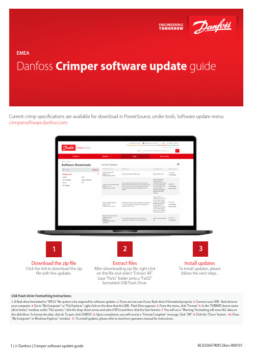
Current crimp specifications are available for download in PowerSource, under tools, Software update menu: Click the link to download the zip file with the updates. To install updates, please follow the next steps .After downloading zip file, right click on the file and select “Extract All”.Save “Parts” folder onto a “Fat32” formatted USB Flash Drive. Download the zip fileExtract files Install updates123USB Flash Drive Formatting Instructions:1. A flash drive formatted to “FAT32” file system is be required for software updates.2. If you are not sure if your flash drive if formatted properly.3. Connect your USB - flash drive to your computer.4. Go to “My Computer” or “File Explorer”, right click on the drive that the USB - Flash Drive appears.5. From the menu, click “Format”6. In the “FORMAT device name (drive letter)” window, under “File system,” click the drop-down arrow and select FAT32 and then click the Start button.7. You will see a “Warning: Formatting will erase ALL data on this disk/drive. To format the disk, click ok. To quit, click CANCEL”.8. Upon completion, you will receive a “Format Complete” message. Click “OK”.9. Click the “Close” button. 10. Close “My Computer” or Windows Explorer” window. 11. To install updates, please refer to machines operators manual for instructions.Loading Crimp Update1. Put USB device in the back of the Machine – choose one of the plugs3. Type in User: user / Password: user4. After successful update - go back to the Start screenLoading Crimp UpdateAbout Danfoss Power Solutions FC Danfoss hoses, fittings, and tooling provide the ultimate fluid conveyance solutions for a variety of equipment and applications around the world. We proudly engineer to support a sustainable future for tomorrow.To learn more please visit: /en/about-danfoss/our-businesses/power-solutionsDanfoss Power Solutions 14615 Lone Oak Road Eden Prairie, MN 55344, USA Phone: 952-937-9800Danfoss Power Solutions (US) Company2800 East 13th Street Ames, IA 50010, USA Phone: +1 515-239-6000Danfoss Power Solutions GmbH & Co.OHG Krokamp 35D-2439 Neumünster, Germany Phone: +49 4321 871 0Danfoss Power Solutions ApS Nordborgveg 81DK-6430 Nordborg, Denmark Phone: +45 7488 2222Danfoss Power Solutions Trade (Shanghai) Co. Ltd.Building #22, No 1000 Jin Hai Rd Jin Qiao, Pudong New District Shanghai, China 201206Phone: +86 21 3418 5200w Danfoss Power Solutions II GmbH Fluid Conveyance Dr. -Reckeweg-Str. 1DE-76532 Baden-Baden, Germany Tel.: +49 7221 6820Danfoss Power Solutions GmbH & Co.OHG Krokamp 35D-2439 Neumünster, GermanyPhone: +49 4321 8710Danfoss Power Solutions (US) Company 2800 East 13th Street Ames, IA 50010, USA Phone: +1 515-239-6000Danfoss Power Solutions ApS Nordborgveg 81 DK-6430 Nordborg, Denmark Phone: +45 7488 2222Danfoss Power Solutions Trade (Shanghai) Co. Ltd. Building #22, No 1000 Jin Hai Rd Jin Qiao, Pudong New District Shanghai, China 201206 Phone: +86 21 3418 5200wAbout Danfoss Power Solutions FCDanfoss hoses, fittings, and tooling provide the ultimate fluid conveyance solutions for a variety of equipment and applications around the world. We proudly engineer to support a sustainable future for tomorrow. To learn more please visit: /en/about-danfoss/our-businesses/power-solutions。
ICP DAS LC-131用户手册说明书
LC-131 User Manual WarrantyAll products manufactured by ICP DAS are under warranty regarding defective materials for a period of one year from the date of delivery to the original purchaser.WarningICP DAS assumes no liability for any damage resulting from the use of this product. ICP DAS reserves the right to change this manual at any time without notification. The information furnished by ICP DAS is believed to be accurate and reliable. However, no responsibility is assumed by ICP DAS for its use, nor for any infringements of patents or other rights of third parties resulting from its use.CopyrightCopyright© 1999 - 2012 ICP DAS. All rights reserved. TrademarksNames are used for identification purposes only and may be registered trademarks of their respective companies. Date: 2013/5/8Table of Contents1 Introduction (3)2 Hardware Information (3)2.1 IO Specifications (3)2.2 System Specifications (4)2.3 Pin Assignments (5)2.4 Wire Connections (6)2.5 Power and Communication (6)2.6 DIP Switch and Jumper Settings (7)3 Modbus Address Mapping (8)1 IntroductionThe LC-131 is an easy-to-use digital input module, equipped with 3-channel digital input, functions open/short circuit detection, and 1-channel relay output. The digital input type is dry contact, meaning that wiring is easy. There are two methods of controlling the relay inputs, either directly from the digital output or via a remote host. Settings, such as communication protocol and node address can be configured either via hardware or via software, depending on the situation. The module has also passed + / -4 kV ESD reliability test, and is designed to operate in harsh environments.2 Hardware Information2.1 IO SpecificationsDigital InputChannels 3Type DryOn V oltage Level Close to GNDOff V oltage Level OpenMax. Count 16-bit (65535)Max. Input Frequency 100 HzCountersMin. Pulse Width 5 msShort Circuit Detection Yes, optioned external terminal resistance of 1 K Ohms is requiredRelay OutputChannels 1 Type Power Relay, Form A (SPST N.O.) Operating V oltage 250 V AC or 30 VDCMax. Load Current 16 A (Res. Load)Operate Time 15 ms Max.Release Time 5 ms Max.Mechanical Endurance 10,000,000 ops.Electrical Endurance 50,000 ops.Power-on and Safe Values Yes, programmable2.2 System SpecificationsCommunicationInterface RS-485 Format N,8,1 Baud Rate 1200 ~ 115200 bpsProtocol DCON, Modbus RTUNode Addresses 96 ~ 127Connector RJ-11LED IndicatorsPower 1 LED as Power IndicatorEMS ProtectionESD (IEC 61000-4-2) ±4 kV Contact for Each Terminal ±8 kV Air for Random PointEFT (IEC 61000-4-4) ±4 kV for Power LinePowerReverse Polarity Protection YesPowered from Terminal Block Yes, 10 ~ 30 VDCConsumption 0.8WMax. MechanicalDimensions (W x L x H) 52 mm x 98 mm x 27 mmInstallation ScrewMounting EnvironmentOperating Temperature -25°C ~ +75°CStorage Temperature -30°C ~ +75°CHumidity 10 ~ 95% RH, Non-condensing2.3 Pin AssignmentsRJ-11 ConnectorPin Descriptions1+VS Power Input V oltage (+10 VDC ~ 30 VDC)23 DATA+RS-485 Serial Communication Interface4 DATA-5GND Ground62.4 Wire Connections2.5 Power and Communication2.6 DIP Switch and Jumper Settings ON DCON ProtocolSW1 OFF Modbus RTU ProtocolON Software ConfigurationSW2 OFF Hardware ConfigurationON High Node AddressSW3 OFF Low Node AddressON INIT ModeSW4 OFF Normal ModeAddress Settings via Hardware Configuration0 ~ F for Addresses 96 ~ 111(Low Node Address)0 ~ F for Addresses 112 ~ 127(High Node Address)3 Modbus Address MappingAddress Description Attribute 30001 ~ 30004 Counter value of digital input R 40481 Firmware version (low word) R 40482 Firmware version (high word) R 40483 Module name (low word) R 40484 Module name (high word) R 40485 Module address, valid range: 1 ~ 247 R/WR/W5:040486 BitsBaud rate, valid range: 3 ~ 10Bits 7:600: no parity, 1 stop bit10: even parity, 1 stop bit11: odd parity , 1 stop bit40488 Modbus response delay time in ms, valid range: 0 ~ 30 R/W 40489 Host watchdog timeout value, 0 ~ 255, in 0.1s R/W 40492 Host watchdog timeout count, write 0 to clear R/W 10033 ~ 10036 Digital input value of channel 0 ~ 3 R 10065 ~ 10068 High latched values of DI R 10073 ~ 10076 High latched values of DO R 10097 ~ 10100 Low latched values of DI R 10105 ~ 10108 Low latched values of DO R 10225 ~ 10227 Short circuit status of DI R 00001 Digital output value of channel 0 R/W 00129 Safe value of digital output channel 0 R/W 00161 Power on value of digital output channel 0 R/W 00193 ~ 00196 Counter update trigger edge of channel 0 ~ 3 R/W 00257 Protocol selection, 0: DCON, 1: Modbus R/W 00260 Modbus host watchdog modeR/W0: same as I-70001: can use AO and DO command to clear hostwatchdog timeout status00261 1: enable, 0: disable host watchdog R/W 00262 1: enable, 0: disable alarm R/W 00263 Alarm type, 0 -> momentary, 1-> latched R/W 00264 Write 1 to clear latched DIO WAddress Description Attribute 00265 DI active state, 0: normal, 1: inverse R/W 00266 DO active state, 0: normal, 1:inverse R/WR/W 00270 Host watch dog timeout status, write 1 to clear hostwatch dog timeout statusR 00273 Reset status, 1: first read after powered on, 0: not thefirst read after powered on00282 Write 1 to clear latched alarm W 00513 ~ 00518 Write 1 to clear counter value of channel 0 ~ 3 W 00545 ~ Enable/disable alarm on DI channels R/W 00553 ~ Enable/disable alarm on short circuit R/W 00577 ~ Status of alarm on DI channels R 00585 ~ Status of alarm on short circuit R。
朗尔易链多媒体系统更新指南说明书

Installation guide for updatingyour EASY LINK multimedia systemRENAULT EASY LINKAttention:this update works only on Renault vehicles equipped with 7”and 9.3”EASY LINKscreens.123How do I get system updates?For each of these steps, be sure to:•Keep the engine on, without driving, to preserve battery power•The update is valid for your vehicle only. Plugging the USB key into another vehicle maycause the multimedia system to malfunction, for which you would be responsible•Do not remove the USB key, and complete the update with the vehicle stationary and theengine onWhy should you do this update?It gives you access to:-the latest software developments,-new features,-improved design and ergonomics.Prerequisites: Use a USB key in FAT32 formatEnsure that you have a USB key in FAT32format witha capacity of16GB or32GB.To check the format of your USB key:connect it to yourcomputer,click on the key,then click the“Properties”tab.•Follow the instructions on all the pages.•Make sure that your Internet connection is active throughout the entire procedure.•Do not interrupt the download process..1How do I complete the update?Download the update version available on the Renault EASY CONNECT website for your countryExample screen. The version bears the number indicated at the time of download.How do I complete the update?Unzip the downloaded folder on your computer:Copy the entire contents of the unzipped file onto your USB key.•The previously empty USB key should contain only the extracted files23•To unzip the downloaded folder, we recommend using http://7zip.fr/•Be careful not to rename or modify the extracted filesTo extract a file, right-click on it then select the option“Extract All”How do I complete the update?Start the engine and connect your USB key to one of the USB ports in the centre console.24•For safety reasons, ensure the vehicle is stationary when carrying out this operation. •Make sure you keep the engine on to avoid draining your battery.•For fuel-powered vehicles, carry out the update in a ventilated location (preferably outside).•Keep the USB key plugged in for the entire duration of these steps to avoid interrupting the update.•Be sure to use one USB key per vehicle and per download. (Do not use the same update for another vehicle.)Plugging the USB key into another vehicle may cause the multimedia system to malfunction, for which you would be responsible.The system will detect the USB key and begin verifying the integrity of theupdate content automatically.If the USB key’s contents are corrupted,an error message will appear prompting the user to download the content again.No action is required by the user.This process takes up to 10minutes.How do I complete the update?25•The update may take up to 25 minutes.•Make sure you keep the engine on to avoid draining your battery.•Keep the USB key plugged in for the entire duration of these steps to avoid interrupting the update.Important: Driver-assistance systems and the standard available features (radio, Bluetooth connection, navigation, etc.) will not be accessible during the last 10 minutes of the update.The system will detect the update.A screen will appear,giving you 30seconds to accept or refuse the update.If you tap “Yes”:the update is launchedIf you tap “No”:the installation is interrupted,and you can update your system at a later timeIf you do nothing for the 30seconds:the update is launched automaticallyOnce the content has been verified successfully,an installation message will bedisplayedHow do I complete the update?6If you accepted the update,wait•Do not be alarmed: a series of blank screens and screens indicating the time remaining will appear.•Make sure you keep the engine on to avoid draining your battery.•Keep the USB key plugged in for the entire duration of these steps to avoid interrupting the update.•Important: Driver-assistance systems and the standard available features (radio, Bluetooth connection, navigation, etc.) will notbe accessible during the last 10 minutes of the update.•Once the installation is complete, the system will reboot, once or several times, and a blank screen may appear for severalminutes. Simply wait, keep the USB connected, and do nothingto the vehicle.How do I complete the update?Tap “OK”once the software has been updated.Once the software has been updated, the following message is displayed:7This final message may not appear.The screen remains black after the last reboot.Exit and lock your vehicle.Your EASY LINK will be updated after 10minutes.Remember to remove the USB key.The installation is complete.You can now remove the USB key8。
S938t软件升级说明书

MIDH客服技术支持处
软件升级——T卡升级
升级步骤:
1.将update.zip 软件包拷贝到内置或者外置T卡根目录; 2.手机关机下,长按开机键+音量上键+音量下键 ,进入Lenovo-Recovery界面后选择语言(简体中文/English);然后 点击“安装升级包”,会提示“将内置或者外置存储器根目录下的update.zip包安装到系统中”,点击“确定”则开始 进行升级; 3、 升级完成界面会提升“恭喜你安装成功”,然后点击“重启进入新系统”即可。
The End
MIDH客服技术支持处
软件升级——升级步骤
1、双击路径: \S938t_S116_131231\S938t_upgrade_tool_20131106 (v5.1343.01)\S938t_升级工具_20131106(v5.1343.01)软 件中Flash_tool升级工具 ,运行界面如下: 2、点击菜单“Options”,下拉菜单“Option… Ctrl+O”,如下图所示:
注意:本次升级以S938t_S116_131231版本为例,实际升级时请使用最新版本软件或需要的 版本。
MIDH客服技术支持处
软件升级——驱动安装
1、手机关机,用升级线连接手机和电脑,当PC 未安装过驱动时会弹出新硬件向导,如下: 2、选择“从列表或指定位置安装(高级)(S)”
MIDH客服技术支持处
MIDH客服技术支持处
软件升级——升级步骤
7、导入软件OK: 8、先选择Firmware Upgrade,再点击Download:
MIDH客服技术支持处
软件升级——升级步骤
9、手机关机插入USB数据线即可正常下载:
10、升级成功界面如下:
软件升级的说明书

目录S870e软件升级说明书 ............................................................................................错误!未定义书签。
目录 (1)第一章升级前软硬件准备 (2)1.1 软件准备工作 (2)1.1.1 升级工具软件 (2)1.1.2 升级数据线驱动程序 (2)第二章、驱动安装 (2)第三章升级步骤 (2)第四章升级完毕开机检验 (5)第一章升级前软硬件准备1.1 软件准备工作1.1.1 升级工具软件1.1.2 升级数据线驱动程序第二章、驱动安装本款手机用T卡升级,无需在电脑上安装驱动。
第三章升级步骤注意事项:1. 升级操作方法,分为自动升级和手动升级两种操作模式。
自动升级适用于待升级手机当前能够正常启动并进入设置菜单的场合;若无法正常启动并进入桌面的场合请使用手动升级(例如开机后停止在开机LOGO界面,进入系统后频繁提示进程错误)2. 由于升级过程开始时会首先进行恢复出厂设置的操作,请务必提前备份必要信息。
3. T 卡升级之前,请确认 T 卡已经插好,被手机识别。
4. 尽量选取1G以上的卡,小于1G的卡由于出厂时间久远,可能有兼容性的问题。
5. T 卡升级过程中,请确保电池电量充足。
为了保证电池不会松动脱落,请盖上盖板。
6. 固件版本升级包请勿解压,解压后无法使用!自动升级操作方法:(1)将固件版本升级包(.zip的压缩文件) 拷贝到Micro SD卡中。
(目录深度不限,但是建议目录深度不要过深,也尽量不要使用中文文件目录名,避免后续操作繁琐。
)(2)手机正常启动后,点击下方中央的主菜单键进入主菜单,并点击“设置”,(3)在“设置”菜单中,下翻到最底部,点击进入“关于手机”,(4)在“关于手机”界面中点击选择“系统更新”,(5)在弹出的升级类型选项框中选择“本地更新”,(6)选择“外部存储卡”,切换到文件管理器页面时,在列出的Micro SD卡中所有文件中点击固件版本升级包;(7)选择升级包后,系统会自动提示重启,点击“确定”后开始自动升级流程。
地面综合观测业务软件ISOSVer0331升级安装指南
地面综合观测业务软件ISOS(Ver3.0.1.331)升级安装指南(升级前务必阅读)中国气象局气象探测中心2019年3月前言根据地面、辐射、酸雨气象数据格式标准化业务切换方案安排,2019年4月1日起湖南、广西所有国家级地面气象观测站将ISOS(Ver3.0.1.0)升级切换为ISOS(Ver3.0.1.331)(以下简称为ISOS(Ver3.0.1.331))。
为满足标准化业务工作需要,根据BUFR数据文件中天气现象、冻土等规则调整要求,中国气象局气象探测中心组织开发了ISOS(Ver3.0.1.331),特制定“地面综合观测业务软件ISOS(Ver3.0.1.331)升级指南”(以下简称“升级指南”),指导台站顺利开展软件升级工作。
ISOS(Ver3.0.1.331)软件对部分BUFR编码进行了调整。
“省级自定与应急观测”界面增加压、温、湿、风、能见度、地温、“WWW1W2天气现象电码”等人工质控功能,方便台站在自定观测时次进行人工质控。
2019年3月31日20时(北京时,下同)至21时之间,湖北省所有国家级地面气象观测软件均需升级切换至ISOS(Ver3.0.1.331)。
《升级指南》由中国气象局气象探测中心张鑫主持编写,宋树礼、张志龙等同志参加编写,宋树礼同志负责统稿。
在此,编写组向参与测试ISOS (Ver3.0.1.331)软件的同行专家表示衷心的感谢!中国气象局气象探测中心 2019年3月31日目录1、参数备份 (1)(1)参数截图备份 (1)(2)参数导出备份 (1)(3)参数拷贝备份 (1)2、卸载ISOS(Ver3.0.1.0)并对数据库备份 (1)3、安装ISOS(Ver3.0.1.331) (1)4、ISOS(Ver3.0.1.331)参数设置 (5)(1)自动项目挂接设置 (6)(2)台站参数设置 (7)(3)自定项目参数 (9)(4)分钟极值参数 (11)(5)小时极值参数 (12)(6)系统设置 (12)5、备份参数拷入及通信参数设置 (13)6、BUFR格式文件补发 (13)7、数据文件生成情况检查 (14)(1)地面正点数据文件检查 (14)(2)辐射正点数据文件检查 (14)(3)基准辐射正点数据文件检查 (14)(4)日照数据文件检查 (14)(5)日数据文件检查 (14)8、“自定观测项目”→“省级自定与应急观测”操作界面调整内容 (14)地面综合观测业务软件(Ver3.0.1.331)升级安装步骤1、参数备份(1)参数截图备份查看天气现象等通信参数的“命令重试次数”并记录或截图保存。
Mazda NB1导航设备软件更新指南说明书
July 2012Steps for updating your softwareImportant Guidelines1. Remove the memory card from the car.2. Prepare the computer to download updates.3. Download the updates.4. Insert the memory card into the navigation device.5. Update the navigation device with the latest software.• Make sure that your computer has at least 4GB of free space available. • Make sure that your memory card reader supports SD-HC memory cards.• Make sure that your computer will not go into an energy-saving mode during the software update. See the manual for your computer for more information.• Do not remove the memory card until you are told that it is safe to do so.Depending on the configuration of your navigation device, the order in which the steps occur in this document may differ slightly from the order in which they occur on your device. Hence we recommend that you read ALL of this document before you start your software update.Depending on the configuration of your computer and internet connection, it can take two hours or more to download a map. The download of a software update istypically much faster.Remove the memory card from the carMake sure that the car ignition is turned off.Tip: Wait at least 6 seconds after turning off theignition.Locate the navigation device in your car. In mostcars it is located on the left side of the steeringwheel towards the door.You can see a sliding door as shown in thepicture. Open the door by sliding it to the right.Push the memory card in a little until it goes nofurther. A spring now forces the card to come outfar enough so that you can take hold of the card.Note: The first few times you remove the memory card you may needa bit more force than usual. This is normal. Dono use any tools to remove the memory card.T ake the memory card out of the navigationdevice. T ake the card to the computer that youare going to use to update the software on thecard.Prepare the computer to download updatesStep 2.1Install TomTom HOMEDownload T omT om HOME from: /homeClick Download HOME followed by one of the Download buttons:• Click Download on the left side for installation on a Windows computer.• Click Download on the right side for installation on a computer with Mac OS X. Follow the prompts to install and start the application.T omT om HOME starts automatically.You may be asked to install the Mazda add-on.If prompted, click Install to do so.Step 2.2Make the memory card available to the computerIf your computer has a card reader, insert the memory card into the slot in the card reader.If your computer does not have a card reader, you will need an external card reader. Please see the instructions for the card reader on how to connect it to your computer. When installed you can insert the memory card as documented in the manual for the card reader.T omT om HOME starts automatically when the memory card is seen by the computer. Note that this may take a few seconds. If T omT om HOME does not start, check to make sure that your card reader supports SD-HC cards.After inserting the memorycard, T omT om HOMErecognises your navigationdevice.Insert memory cardStep 3Download the updatesStep 3.1Application UpdatesT omT om offers a number of downloads to enhance your navigation device. Downloads can include software updates, Map Share map corrections and the QuickGPSFix solution to make finding your location faster.The Updates screen in T omT om HOME lists the updates that are available for your device. In the example shown above there is a new software update for your navigation device as well as a Map Share update. If you see a yellow warning triangle, click on Log in now to see items for registered users.Map Share is a free offering for our customers that provides free updates to the map that were reported and shared by other T omT om customers. You can also make your own changes. See the manual for your device.Click the Update and install button to download your updates.Step 3.2Checking for Latest Map GuaranteeDownload and installation of your chosen items starts. Do not remove the memory card while download and installation is in progress. Make sure the computer does not go into an energy-saving mode as this will interrupt the download and installation. See the manual for your computer .After all the items have been installed, click Done .T omT om products offer one free map update after buying the navigation device. You need to follow the steps below within 60 days after purchase to get this free service.Tip: Downloading a new map may take a long time due to the size of the map. See the online help for your firewall if the download is blocked.Insert the memory card again. If the T omT om HOME main menu is not shown as on the left, close any other screens.Go to the T ools menu and click Get Latest Map Guarantee .You can now remove the memory card from the computer.While the application is checking for a free map update, you may see the following message. It reminds you that you can make a backup of your memory card.We recommend that you skip this step for now by pressing Cancel and that you make a backup after you have updated your memory card. You can do this by re-inserting the memory card into your card reader.T o download maps, you need a MyT omT om account. The following screens guide you through creating a MyT omT om account. If you already have an account, you can enter your email address and password.Your navigation device is linked to your MyT omT om account. Any content such as maps that you subsequently buy can be downloaded more than once if necessary.If you already have an account, enter your email address and password.If you don’t have an account click Create account.Step 3.3Logging into your accountThe following screen is shown when you are eligible for a free map update.If you are creating a new account, type in your email address and a password that you would like to use.Click Create account to continue.If you are creating a new account, you see this screen. It asks for confirmation to link the current navigation device, stored on your memory card, with the account you just created.Click Link device .Step 3.4Using your Latest Map GuaranteeThe next screen shows the map that will be downloaded.Downloading starts.Note: Do not remove the memory card while the map is downloading. Downloading a map may take more than two hours.When completed the following screen is shown.Click OK and then click Done .You can now remove the memory card from the computer.Click Install now.Make sure that the car ignition is turned off.Tip: Wait at least 6 seconds after turning off the ignition.Hold the memory card as shown on the left. Make sure you can see the label when inserting the memory card into the navigation device.Once the memory card has been inserted, slide the door back to the left.Turn on the ignition.Wait for the radio to turn on.After 15 seconds, press the NAV button. The screen on the left will be shown. If the screen does not appear, try pressing the NAV button a few more times.Wait for this screen to be shown. Then press the button on the right (green). The update is now started. A progress bar will be shown.Step 4Insert the memory card into the navigation deviceStep 5Update the navigation device with the latest softwareAfter the update is completed the screen on the left isshown.Turn off the ignition. Wait for 6 seconds and then turnignition on.After about 15 seconds, press the NAV button for thenavigation screen to become available.Your device has been updated.Important: T o prevent damage to your navigation device, do not turn off the ignition during the software update.。
- 1、下载文档前请自行甄别文档内容的完整性,平台不提供额外的编辑、内容补充、找答案等附加服务。
- 2、"仅部分预览"的文档,不可在线预览部分如存在完整性等问题,可反馈申请退款(可完整预览的文档不适用该条件!)。
- 3、如文档侵犯您的权益,请联系客服反馈,我们会尽快为您处理(人工客服工作时间:9:00-18:30)。
IND131/331仪表软件更新说明
1.首先确保PC上安装有FlashMagic软件,如果没有安装过,可将附件中的FlashMagic.exe1
重命名为FlashMagic.exe。
双击该文件安装即可。
2.PC与IND131/331仪表的连接。
将PC机的串口通过串口线与IND131/331仪表相连。
串口线连接方式如下:
PC COM1(默认为COM1) IND131/331 COM1
9针接头 串口端子
2 RXD --------------------------------------- 1 TXD
3 TXD --------------------------------------- 2 RXD
5 GND --------------------------------------- 3 GND
3.在仪表上电之前将主板的SWITCH-3置为ON状态,然后上电。
如下图所示SWITCH-3。
4.打开FlashMagic.如下图所示选择配置参数。
5.至此完成IND131/331仪表的软件升级。
断开电源,将SWITCH-3置为OFF状态。
再打开电源,进入菜单,在Recall菜单中查询S/W Info可以查看仪表中所烧录的软件版本。
附:避免软件升级之后重新标定的方法:
1.确认当前仪表在开机的时候没有SD卡。
2.关闭仪表,插入SD卡,重新上电。
3.在仪表显示“Save setup file”的时候 ,通过T键或者C键选择”Yes”;
在“File Name?”界面输入要保存的文件名,比如File_02,按打印键确认;仪表显示 “Save Complete”.
至此文件File_02.txt保存在SD卡中。
4.给仪表升级软件。
5.软件升级完成之后断电,将主板的SWITCH-2和SWITCH-4置为ON状态,重新上电。
仪表显示”WARNING! Master Reset Continue?”,按打印键确认。
6.仪表断电。
7.将主板的SWITCH-2和SWITCH-4还原为OFF状态,SD卡插入仪表,重新上电.
8.仪表显示”保存设定文件”,选择”否”,按打印键确认。
仪表显示”恢复设定文件”,选择”是”,打印键确认,选择刚才保存的文件File_02,打印键确认, 仪表显示”包括标定?”,选择”是”,打印键确认。
至此完成了所有参数的设定,进入菜单,查看当前Capacity和分度值与软件升级之前一致。
