无线客户端操作说明
中国电信无线宽带客户端 说明书

中国电信无线宽带客户端使用手册中国电信股份有限公司中国电信无线宽带客户端使用手册目录一、无线宽带客户端介绍 (2)二、无线宽带客户端安装说明 (2)1.运行申请无线宽带业务时获得的光盘进行安装 (2)2.启动安装程序 (2)3.安装程序启动,进入协议条款界面 (2)4.选择安装类型 (3)5.完成安装 (4)三、无线宽带客户端界面简介 (6)1.主界面介绍 (6)2.状态信息 (6)四、网络接入服务 (7)1.无线宽带(WLAN)接入 (7)2.无线宽带(3G)接入 (7)3.无线宽带(1X)接入 (7)五、无线宽带客户端菜单功能 (8)1.“设置”菜单 (8)2.“帮助”菜单 (9)一、无线宽带客户端介绍无线宽带客户端是中国电信为您提供的网络接入客户端,您可以使用本客户端通过中国电信无线宽带(WLAN)或无线宽带(1X)、无线宽带(3G)网络接入中国电信无线宽带互联网。
注:您需要使用配置有符合802.11b/g标准功能模块或设备的主流笔记本电脑。
客户端支持Windows2000、XP、Vista中文操作系统。
暂不支持Linux、Macintosh系统。
说明:无线宽带(1X)针对的CDMA1X网络,无线宽带(3G)针对的EV-DO RevA网络。
二、无线宽带客户端安装说明1.运行申请无线宽带业务时获得的光盘进行安装点击“安装”按钮直接进入无线宽带客户端安装;图1 光盘自启动界面2.启动安装程序图2 启动安装程序注:此过程根据您的电脑配置不同,可能会持续几分钟,请耐心等待3.安装程序启动,进入协议条款界面1)您必须选择“我同意,我接受以上协议的所有条款”,才能进入下一步安装图3 协议条款界面2)默认勾选“进行快速安装”,选择此项,将客户端直接安装在默认路径下,取消勾选,则请根据向导设置安装路径和程序图标位置。
图4 协议条款界面-快速安装3)单击<下一步>按钮,继续安装过程。
4.选择安装类型1)默认安装方式为“完全安装”(初次安装请务必使用该方式),并将相应数据卡连接电脑。
MOXA AWK-1131A 工业无线AP 客户端说明书
AWK-1131A SeriesEntry-level industrial IEEE802.11a/b/g/n wireless AP/clientFeatures and Benefits•IEEE802.11a/b/g/n AP/client support•Client-based millisecond-level Turbo Roaming•Integrated antenna and power isolation•5GHz DFS channel supportCertificationsIntroductionThe AWK-1131A industrial wireless AP/client meets the growing need for faster data transmission speeds by supporting IEEE802.11n technology with a net data rate of up to300Mbps.The AWK-1131A is compliant with industrial standards and approvals covering operating temperature, power input voltage,surge,ESD,and vibration.The two redundant DC power inputs increase the reliability of the power supply.The AWK-1131A can operate on either the2.4or5GHz bands and is backwards-compatible with existing802.11a/b/g deployments to future-proof your wireless investments.Improved Higher Data Rate and Channel Capacity•High-speed wireless connectivity with up to300Mbps data rate•MIMO technology to improve the capability of transmitting and receiving multiple data streams•Increased channel width with channel bonding technology•Supports flexible channel selection to build up wireless communication system with DFSSpecifications for Industrial-Grade Applications•Redundant DC power inputs•Integrated isolation design with enhanced protection against environmental interference•Compact aluminum housing,IP30-ratedSpecificationsWLAN InterfaceWLAN Standards802.11a/b/g/n802.11i Wireless SecurityModulation Type DSSSMIMO-OFDMOFDMFrequency Band for US(20MHz operating channels) 2.412to2.462GHz(11channels)5.180to5.240GHz(4channels)5.260to5.320GHz(4channels)15.500to5.700GHz(11channels)15.745to5.825GHz(5channels)Frequency Band for EU(20MHz operating channels) 2.412to2.472GHz(13channels)5.180to5.240GHz(4channels)5.260to5.320GHz(4channels)15.500to5.700GHz(11channels)1Frequency Band for JP(20MHz operating channels) 2.412to2.484GHz(14channels)5.180to5.240GHz(4channels)5.260to5.320GHz(4channels)25.500to5.700GHz(11channels)2Wireless Security WEP encryption(64-bit and128-bit)WPA/WPA2-Enterprise(IEEE802.1X/RADIUS,TKIP,AES)WPA/WPA2-PersonalTransmission Rate802.11b:1to11Mbps802.11a/g:6to54Mbps802.11n:6.5to300MbpsTransmitter Power for802.11a23±1.5dBm@6to24Mbps21±1.5dBm@36Mbps20±1.5dBm@48Mbps18±1.5dBm@54MbpsTransmitter Power for802.11b26±1.5dBm@1Mbps26±1.5dBm@2Mbps26±1.5dBm@5.5Mbps25±1.5dBm@11MbpsTransmitter Power for802.11g23±1.5dBm@6to24Mbps21±1.5dBm@36Mbps19±1.5dBm@48Mbps18±1.5dBm@54MbpsTransmitter Power for802.11n(2.4GHz)23±1.5dBm@MCS0/820MHz18±1.5dBm@MCS7/1520MHz23±1.5dBm@MCS0/840MHz17±1.5dBm@MCS7/1540MHzTransmitter Power for802.11n(5GHz)23±1.5dBm@MCS0/820MHz18±1.5dBm@MCS7/1520MHz23±1.5dBm@MCS0/840MHz17±1.5dBm@MCS7/1540MHzTransmitter Power2.4GHz26dBm18dBm18dBm5GHz(UNII-1)23dBm21dBm21dBm5GHz(UNII-2)23dBm21dBm21dBm5GHz(UNII-2e)23dBm23dBm23dBm5GHz(UNII-3)23dBm––Note:Based on regional regulations,the maximum transmission power allowed onthe UNII bands is restricted in the firmware,as indicated above.Receiver Sensitivity for802.11a-90dBm@6Mbps-88dBm@9Mbps-88dBm@12Mbps-85dBm@18Mbps-81dBm@24Mbps-78dBm@36Mbps-74dBm@48Mbps-72dBm@54MbpsReceiver Sensitivity for802.11b-93dBm@1Mbps-93dBm@2Mbps-93dBm@5.5Mbps-88dBm@11MbpsReceiver Sensitivity for802.11g-88dBm@6Mbps-86dBm@9Mbps-85dBm@12Mbps-85dBm@18Mbps-85dBm@24Mbps-82dBm@36Mbps-78dBm@48Mbps-74dBm@54MbpsReceiver Sensitivity for802.11n(2.4GHz)-70dBm@MCS720MHz-69dBm@MCS1520MHz-67dBm@MCS740MHz-67dBm@MCS1540MHzReceiver Sensitivity for802.11n(5GHz)-69dBm@MCS720MHz-71dBm@MCS1520MHz-63dBm@MCS740MHz-68dBm@MCS1540MHzWLAN Operation Mode Access point,Client,SnifferAntenna External,2/2dBi,Omni-directionalAntenna Connectors2RP-SMA femaleEthernet Interface10/100/1000BaseT(X)Ports(RJ45connector)1Standards IEEE802.1X for authenticationIEEE802.3for10BaseTIEEE802.3ab for1000BaseT(X)IEEE802.3u for100BaseT(X)Ethernet Software FeaturesManagement DHCP Server/Client,DNS,HTTP,IPv4,LLDP,Proxy ARP,SMTP,SNMPv1/v2c/v3,Syslog,TCP/IP,Telnet,UDP,Wireless Search Utility,VLAN,MXview,MXconfig Security HTTPS/SSL,RADIUS,SSHTime Management SNTP ClientFirewallFilter ICMP,MAC address,IP protocol,Port-basedSerial InterfaceConsole Port RS-232,8-pin RJ45LED InterfaceLED Indicators PWR,FAULT,STATE,SIGNAL,WLAN,LANInput/Output InterfaceButtons Reset buttonPhysical CharacteristicsHousing MetalIP Rating IP30Dimensions58x115x70mm(2.29x4.53x2.76in)Weight307g(0.68lb)Installation DIN-rail mounting,Wall mounting(with optional kit)Power ParametersInput Current0.56A@12VDC,0.14A@48VDCInput Voltage12to48VDCPower Connector1removable4-contact terminal block(s)Power Consumption 6.96W(max.)Reverse Polarity Protection SupportedEnvironmental LimitsOperating Temperature Standard Models:0to60°C(32to140°F)Wide Temp.Models:-40to75°C(-40to167°F)Storage Temperature(package included)-40to85°C(-40to185°F)Ambient Relative Humidity5to95%(non-condensing)Standards and CertificationsEMC EN55032/24EMI CISPR32,FCC Part15B Class BEMS IEC61000-4-2ESD:Contact:4kV;Air:8kVIEC61000-4-3RS:80MHz to1GHz:10V/mIEC61000-4-4EFT:Power:2kV;Signal:1kVIEC61000-4-5Surge:Power:2kV;Signal:1kVIEC61000-4-6CS:3VIEC61000-4-8PFMFRadio ANATEL,EN300328,EN301489-1/17,EN301893,FCC ID SLE-WAPN008,MIC,NCC,RCM,SRRC,WPC,KC,RCMSafety EN60950-1,UL60950-1Vibration IEC60068-2-6MTBFTime749,476hrsStandards Telcordia SR332WarrantyWarranty Period5yearsDetails See /warrantyPackage ContentsDevice1x AWK-1131Series wireless AP/clientInstallation Kit1x cap,plastic,for RJ45port1x DIN-rail kitAntenna2x2.4/5GHz antennaDocumentation1x quick installation guide1x warranty cardDimensionsOrdering InformationModel Name Band Standards Operating Temp. AWK-1131A-EU EU802.11a/b/g/n0to60°C AWK-1131A-EU-T EU802.11a/b/g/n-40to75°C AWK-1131A-JP JP802.11a/b/g/n0to60°C AWK-1131A-JP-T JP802.11a/b/g/n-40to75°C AWK-1131A-US US802.11a/b/g/n0to60°C AWK-1131A-US-T US802.11a/b/g/n-40to75°C Accessories(sold separately)AntennasANT-WDB-ANF-0407 2.4/5GHz,omni-directional antenna,4/7dBi,N-type(male)ANT-WDB-ANF-0609 2.4/5GHz,omni-directional antenna,6/9dBi,N-type(female)ANT-WDB-ANM-0306 2.4/5GHz,omni-directional antenna,3/6dBi,N-type(male)ANT-WDB-ANM-0407Dual-band omni-directional antennas,4dBi at2.4GHz or7dBi at5GHzANT-WDB-ANM-0502 2.4/5GHz,omni-directional antenna,5/2dBi,N-type(male)ANT-WDB-ANM-0609 2.4/5GHz,omni-directional antenna,6/9dBi,N-type(male)ANT-WDB-ARM-02 2.4/5GHz,omni-directional rubber duck antenna,2dBi,RP-SMA(male)ANT-WDB-ARM-0202 2.4/5GHz,panel antenna,1.8/1.8dBi,RP-SMA(male)ANT-WDB-PNF-1518 2.4/5GHz,panel antenna,15/18dBi,N-type(female)MAT-WDB-CA-RM-2-0205 2.4/5GHz,ceiling antenna,2/5dBi,MIMO2x2,RP-SMA-type(male)MAT-WDB-DA-RM-2-0203-1m 2.4/5GHz,desktop antenna,2/3dBi,MIMO2x2,RP-SMA-type(male),1m cableMAT-WDB-PA-NF-2-0708 2.4/5GHz,panel antenna,7/8dBi,MIMO2x2,N-type(female)ANT-WSB5-ANF-125GHz,omni-directional antenna,12dBi,N-type(female)ANT-WSB5-PNF-185GHz,directional panel antenna,18dBi,N-type(female)ANT-WSB-PNF-12 2.4GHz,directional panel antenna,12dBi,N-type(female)ANT-WSB-PNF-18 2.4GHz,directional panel antenna,18dBi,N-type(female)ANT-WSB-AHRM-05-1.5m 2.4GHz,omni-directional/dipole antenna,5dBi,RP-SMA(male),1.5m cableWireless AdaptorsA-ADP-RJ458P-DB9F-ABC01DB9female to RJ45connector for the ABC-01Wireless Antenna CableA-CRF-RFRM-R4-150RF magnetic stand,RP-SMA(male)to RP-SMA(female),RG-174/U cable,1.5mA-CRF-RFRM-S2-60SS402cable,RP-SMA(male)to RP-SMA(female)A-CRF-RMNM-L1-300N-type(male)to RP SMA(male),LMR-195Lite cable,3mA-CRF-RMNM-L1-600N-type(male)to RP SMA(male),LMR-195Lite cable,6mA-CRF-RMNM-L1-900N-type(male)to RP SMA(male),LMR-195Lite cable,9mSurge ArrestorA-SA-NFNF-01Surge arrestor,N-type(female)to N-type(female)A-SA-NMNF-01Surge arrester,N-type(female)to N-type(male)Wireless Terminating ResistorA-TRM-50-RM Termination resistor,50ohms,N-type maleWireless Antenna CableCRF-N0117SA-3M N-type(male)to RP SMA(male),CFD200cable,3mWall-Mounting KitsWK-51-01Wall-mounting kit,2plates,6screws,51.6x67x2mm©Moxa Inc.All rights reserved.Updated Nov12,2018.This document and any portion thereof may not be reproduced or used in any manner whatsoever without the express written permission of Moxa Inc.Product specifications subject to change without notice.Visit our website for the most up-to-date product information.。
无线数据终端怎么使用

无线数据终端怎么使用无线数据终端是一种便捷的设备,用于在没有固定网络连接的环境下进行数据通信。
它可以通过无线网络与其他设备进行通信,并实现数据传输和接收的功能。
无线数据终端的使用方法相对简单,本文将介绍无线数据终端的基本用法以及注意事项。
首先,使用无线数据终端之前,我们需要确认一些基本的配置信息。
无线数据终端通常需要连接到一个无线网络,因此我们需要确保终端设备的无线功能已经开启,并正确的连接到一个可用的无线网络上。
通常,无线数据终端会提供一个配置界面,我们可以在配置界面中输入无线网络的名称(SSID)和密码,以便连接到网络。
在输入完毕后,保存配置并等待终端设备重新连接到网络。
当无线数据终端成功连接到无线网络后,我们可以开始使用它进行数据通信。
无线数据终端通常支持多种数据传输协议,如HTTP、FTP和TCP/IP等。
根据实际需求,我们可以选择合适的协议来进行数据传输。
下面将介绍几种常见的数据传输协议的使用方法。
首先,HTTP是一种常用的数据传输协议,用于在客户端和服务器之间传输数据。
无线数据终端可以作为一个HTTP客户端,从服务器上获取数据,或者将数据发送到服务器上。
我们可以使用终端设备上的浏览器来访问一个特定的URL,以获取服务器上的数据。
也可以使用HTTP客户端库来编写一个自定义的应用程序,实现数据的传输和接收。
其次,FTP是一种用于文件传输的协议,它可以用于将文件从一个设备传输到另一个设备上。
无线数据终端可以作为FTP客户端,从FTP服务器上下载或上传文件。
我们可以使用终端设备上的FTP客户端软件,输入FTP服务器的地址、用户名和密码,以及要下载或上传的文件名或路径,来完成文件传输的操作。
另外,TCP/IP是一种广泛使用的网络协议,用于实现数据的传输和接收。
无线数据终端可以使用TCP/IP协议与其他设备进行通信。
我们可以编写一个基于TCP/IP协议的应用程序,实现数据的传输和接收。
通过指定目标设备的IP地址和端口号,我们可以建立一个TCP/IP连接,并在连接上发送和接收数据。
apple iphone无线局域网客户端配置指南说明书
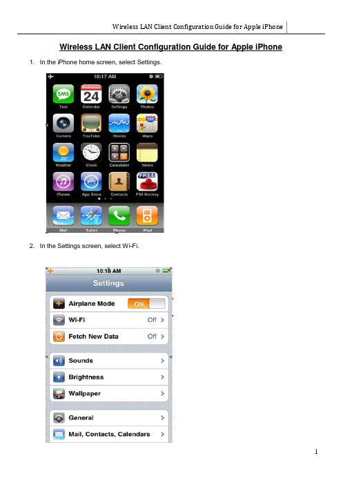
Wireless LAN Client Configuration Guide for Apple iPhone Wireless LAN Client Configuration Guide for Apple iPhone 1. In the iPhone home screen, select Settings.2. In the Settings screen, select Wi-Fi.Wireless LAN Client Configuration Guide for Apple iPhone3. In the Wi-Fi Networks screen, enable your Wi-Fi if it is off. If Wi-Fi is already enabled, proceed to step4.4. After WI-FI is enabled; a list of available wireless network SSIDs will be displayed. Select the SSID from the list of available networks that you want to connect to. Select other if your network SSID is not displayed.You will be required to enter login credentials if the network has this icon . To enter the advanced settings screen for the wireless network, select.Wireless LAN Client Configuration Guide for Apple iPhone5. Enter the SSID of the wireless network in the Name field.Table 1Note: SSID is case-sensitive.After entering the SSID, select Security to change the security settings.Wireless LAN Client Configuration Guide for Apple iPhone6. In the Security screen, select WPA2 Enterprise.Select Other Network to return to the previous screen.7. Enter your Username and password. Press Join after you had entered your login credentials.For Student Wireless Login to “NYP-Student” SSIDUse Student Portal username and passwordFor Staff Login to “STAFF” SSIDUse Windows Login name and passwordFor adjunct lecturer login to “NYP-Account” SSIDWireless LAN Client Configuration Guide for Apple iPhone8. You will be prompted to accept certificate. Click “Accept”.9. This iconwill be displayed on the top left corner, beside the carrier name, when you areconnected to a Wi-Fi network. There will also be a tick beside the SSID of the connected Wi-Fi network.Wireless LAN Client Configuration Guide for Apple iPhone 10. To check your IP address, select the advance settings.Ensure your setting is set to DHCP.11. You may access internet through the Safari web browser.Connecting to the InternetiPhone connects to the Internet automatically whenever you use Mail, Safari, YouTube, Stocks, Maps, Weather, the App Store or iTunes Wi-Fi Music Store.How iPhone Connects to the InternetiPhone connects to the Internet using either a Wi-Fi network or a cellular data network. iPhone does the following, in order, until connected:Connects over the last Wi-Fi network you used that’s available.If no previously used Wi-Fi networks are available, iPhone shows a list of Wi-Fi networks in range. Tapa network and, if necessary, enter the password to join. Networks that require a password show next to them. You can prevent iPhone from automatically showing available networks.If no Wi-Fi networks are available or you choose not to join any, iPhone connects to the Internet over a cellular data network.If no Wi-Fi networks are available and a cellular data network isn’t available, iPhone cannot connect to the Internet.Note: If you’re using an original iPhone, you cannot use the Internet over a cellular data network when you’re on a call. You must have a Wi-Fi connection to use Internet applications while also talking on the phone.Joining a Wi-Fi NetworkThe Wi-Fi settings let you turn on Wi-Fi and join Wi-Fi networks.Turn on Wi-Fi: Choose Settings > Wi-Fi and turn Wi-Fi on.Join a Wi-Fi network: Choose Settings > Wi-Fi, wait a moment as iPhone detects networks in range, then select a network (fees may apply to join some Wi-Fi networks).If necessary, enter a password and tap Join (networks that require a password appear with a lock icon ).Once you’ve joined a Wi-Fi network manually, iPhone automatically connects to it whenever the network is in range. If more than one previously used network is in range, iPhone joins the one last used.When iPhone is connected to a Wi-Fi network, the Wi-Fi icon in the status bar at the top of the screen shows connection strength. The more bars you see, the stronger the connection.Set iPhone to ask if you want to join a new network: Choose Wi-Fi and turn “Ask to Join Networks” on or off.When you are trying to access the Internet, by using Safari or Mail for example, and you are not in range of a Wi-Fi network you have previously used, this option tells iPhone to look for another network. iPhone displays a list of all available Wi-Fi networks that you can choose from. (Networks that require a password appear with a lock icon.)If “Ask to Join Networks” is turned off, you must manually join a network to connect to the Internet when a previously used network or a cellular data network isn’t available.Forget a network, so iPhone doesn’t join it automatically: Choose Wi-Fi and tap next to a network you’ve joined before. Then tap “Forget this Network.”Join a closed Wi-Fi network: To join a Wi-Fi network that isn’t shown in the list of scanned networks, choose Wi-Fi > Other and enter the network name. If the network requires a password, tap Security, tap the type of security the network uses, and enter the password.You must already know the network name, password, and security type to connect to a closed network.Adjust settings to connect to a Wi-Fi network: Choose Wi-Fi, then tap next to a network.Reset the network settings on iPhone: Choose Settings > General > Reset > Reset Network Settings. Erase All Settings: Choose Settings > General > Reset > Erase All Content and SettingsNOTE: use at your own risk.Points to NoteCan’t Make Calls over Wi-Fi.iPhone doesn’t support calling over Wi-Fi.Can’t Text over Wi-Fi.iPhone doesn’t support texting over Wi-Fi.Wi-Fi icon does not display on top left corner (beside carrier name).(/kb/TS1398)Check that the network profile is created correctly and connected to the correct SSID.Check that DHCP is selected for IP Address, instead of Static.Perform a Renew Lease.Attempting to connect to a wireless network with a hidden network name (SSID) may result in no network connection. (/kb/TS1651)If you are unable to initially connect to your hidden wireless network, try sleeping and waking iPhone. Press the sleep/wake button on the iPhone once to put it to sleep.Press the same button again to wake iPhone up again.iPhone should connect on wake.Wireless LAN Client Configuration Guide for Apple iPhoneIf this does not resolve the issue:Check to see if you are able to connect to a different wireless network to test.Check to see if other devices are able to connect to the same wireless network.Try powering the iPhone off and back on again.iPhone User Guide/en_US/iPhone_User_Guide.pdfEnd of Procedure。
无线AP的客户端模式

无线AP的客户端模式(apclient)是什么意思AP Client客户端模式,也俗称“主从模式”,在此模式下工作的AP会被主AP看做是一台无线客户端,其地位就和无线网卡等同。
这种模式的好处在于能方便网管统一的管理子网络。
AP Client客户端模式应用在室外的话,物理结构上象点对多点的连接方式。
AP Client客户端模式区别在于,中心访问节点把远端局域网络看成象一个无线终端的接入,它不限制接入远端AP Client模式的无线访问点连接的局域网络数量和网络连接方式。
所以在设计时,需要充分考虑远端局域网络内部PC的数量和网络使用情况。
中心AP设置成为AP模式,可以提供中心有线局域网络的连接和自身无线覆盖区域的无线终端接入,远端有线局域网络或单台PC电脑所连接的无线访问点(AP)设置成AP Client 客户端模式,远端无线局域网络便可访问中心AP所连接的局域网络。
AP Client客户端模式组建需求AP Client客户端模式有着极其广泛的应用环境,从其技术构架上来看,它与AP基础应用模式结合起来,同时还支持了相邻局域网络的连接。
在主网中与AP基础构架模式差不多,所以能实现网络内部的无线网络组建的需求,还提供了一种主从模式的构架,将相邻的局域网以客户端的模式接入整个网络之中。
这种模式在同时实现了两种需求,便于统一的管理。
在一些公司、企业、小区里面,通常会出现在以一个局域网中需要使用无线办公,需要组建AP基础构架模式的无线网络,而同时还需要连接其他的建筑里的局域网,在连接的时候我们还需要方便统一管理,不能在每栋建筑里都设置一个管理中心。
这个时候建立AP Client客户端模式无线网络,这所有问题都能得到解决。
现在一家工厂里,拥有几个车间厂房和办公大楼。
各个地方都安装了内部的局域网,便于各个车间的管理控制。
现在随着公司的发展业务的壮大,需要统一各个地方的网络管理。
实行集中化管理,使信息实现最大利用化,使各个生产管理的链接得到最合理衔接。
无线客户端操作说明
无线客户端操作说明
简介
无线客户端是一款用于连接无线网络的应用程序。
本文档将介绍如何使用无线客户端连接无线网络、管理连接列表以及解决常见问题。
安装和启动
安装无线客户端
在使用无线客户端之前,您需要进行安装。
请按照以下步骤进行安装:
1.在操作系统的应用商店中搜索无线客户端。
2.找到无线客户端应用程序并点击安装按钮。
3.等待安装完成。
启动无线客户端
安装完成后,您可以在应用程序列表中找到无线客户端的图标。
点击图标以启动无线客户端应用程序。
连接无线网络
扫描无线网络
在无线客户端启动后,您会看到一个扫描按钮。
点击该按钮,无线客户端将开始扫描周围的无线网络。
选择网络
扫描完成后,您将看到一个无线网络列表。
列表中显示了周围可用的无线网络以及它们的信号强度。
1.浏览无线网络列表,找到您想要连接的网络。
2.点击该网络以选择它。
输入密码
如果您连接的无线网络需要密码,无线客户端将要求您输入密码。
1.在密码字段中输入您的无线网络密码。
2.点击连接按钮以连接无线网络。
连接成功
连接成功后,无线客户端将显示您已连接的网络的名称和状态。
管理连接列表
无线客户端允许您管理已保存的连接列表,包括删除不需要的连接和编辑连接配置。
查看连接列表
连接列表包含了您已保存的连接信息,并显示每个连接的状态。
1.点击无线客户端的菜单按钮。
2.选择。
无线AP的客户端模式
无线AP的客户端模式无线AP(Access Point)的客户端模式是指将无线AP设置为接收无线网络信号的设备,以连接到已存在的无线网络中。
在客户端模式下,无线AP的作用类似于一个无线网卡,将无线信号转化为有线信号,以供客户端设备使用。
无线AP的客户端模式可以帮助用户将有线设备连接到无线网络,实现无线和有线网络之间的桥接。
在实际应用中,无线AP的客户端模式有着广泛的应用,例如无线打印机、智能电视、游戏主机等需要通过无线连接网络的设备。
使用无线AP的客户端模式,首先需要将无线AP配置为客户端模式,并设置连接到的已存在的无线网络的SSID(Service Set Identifier)和密码。
接下来,无线AP会扫描周围的无线网络,自动连接到目标网络,并为有线设备提供无线连接。
无线AP的客户端模式的工作原理是将无线信号接收并转化为有线信号,然后通过有线接口将信号传输给有线设备。
有线设备可以是需要连接到无线网络的任何设备,例如电脑、电视、打印机等。
有线设备通过无线AP提供的无线连接与无线网络通信,实现无线网络覆盖到有线设备上。
无线AP的客户端模式的配置相对简单,用户只需要通过无线AP的管理界面或配置工具,设置连接的无线网络的SSID和密码即可。
有一些无线AP可以通过WPS(Wi-Fi Protected Setup)一键连接功能来连接无线网络,这更加方便用户的使用。
无线AP的客户端模式在实际应用中有着广泛的用途。
首先,它可以将有线设备转化为无线设备,例如将智能电视、游戏主机等需要有线网络连接的设备连接到无线网络,方便用户在任何位置享受网络服务。
其次,它可以将没有无线功能的设备连接到无线网络,例如打印机、网络摄像头等设备,以实现远程操作和管理。
此外,无线AP的客户端模式还可以扩大无线网络的覆盖范围,增强无线信号的穿透能力,提高无线网络的稳定性和性能。
总之,无线AP的客户端模式是一种将无线AP配置为接收无线网络信号的设备,以连接到已存在的无线网络中的功能。
摩克斯AWK-5232系列工业IEEE802.11a b g n双频无线AP 桥 客户端说明书
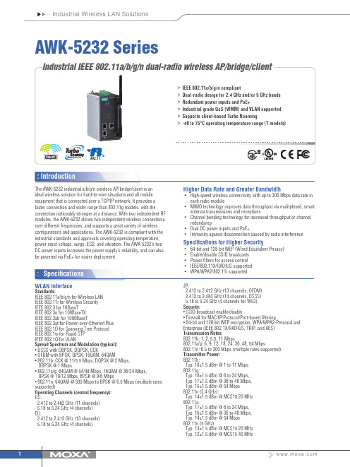
SpecificationsAWK-5232 Seriesequipment that is connected over a TCP/IP network. It provides a faster connection and wider range than 802.11g models, with theconnection noticeably stronger at a distance. With two independent RF modules, the AWK-5232 allows two independent wireless connections over different frequencies, and supports a great variety of wireless configurations and applications. The AWK-5232 is compliant with the industrial standards and approvals covering operating temperature, power input voltage, surge, ESD, and vibration. The AWK-5232’s two DC power inputs increases the power supply’s reliability, and can also be powered via PoE+ for easier deployment.Higher Data Rate and Greater Bandwidth• High-speed wireless connectivity with up to 300 Mbps data rate in each radio module• MIMO technology improves data throughput via mulitplexed, smart antenna transmissions and receptions• Channel bonding technology for increased throughput or channel redundancy• Dual DC power inputs and PoE+• Immunity against disconnection caused by radio interferenceSpecifications for Higher Security• 64-bit and 128-bit WEP (Wired Equivalent Privacy)• Enable/disable SSID broadcasts • Power filters for access control • IEEE/802.11X/RADIUS supported •WPA/WPA2/802.11i supportedWLAN InterfaceStandards:IEEE 802.11a/b/g/n for Wireless LAN IEEE 802.11i for Wireless Security IEEE 802.3 for 10BaseT IEEE 802.3u for 100BaseTX IEEE 802.3ab for 1000BaseTIEEE 802.3at for Power-over-Ethernet Plus IEEE 802.1D for Spanning Tree Protocol IEEE 802.1w for Rapid STP IEEE 802.1Q for VLANSpread Spectrum and Modulation (typical): • DSSS with DBPSK, DQPSK, CCK• OFDM with BPSK, QPSK, 16QAM, 64QAM• 802.11b: CCK @ 11/5.5 Mbps, DQPSK @ 2 Mbps, DBPSK @ 1 Mbps• 802.11a/g: 64QAM @ 54/48 Mbps, 16QAM @ 36/24 Mbps, QPSK @ 18/12 Mbps, BPSK @ 9/6 Mbps•802.11n:64QAM@*********************(multiplerates supported)Operating Channels (central frequency): US:2.412 to 2.462 GHz (11 channels) 5.18 to 5.24 GHz (4 channels) EU:2.412 to 2.472 GHz (13 channels) 5.18 to 5.24 GHz (4 channels)JP:2.412 to 2.472 GHz (13 channels, OFDM) 2.412 to 2.484 GHz (14 channels, DSSS) 5.18 to 5.24 GHz (4 channels for W52)Security:• SSID broadcast enable/disable• Firewall for MAC/IP/Protocol/Port-based filtering• 64-bit and 128-bit WEP encryption, WPA/WPA2-Personal and Enterprise (IEEE 802.1X/RADIUS, TKIP, and AES)Transmission Rates:802.11b: 1, 2, 5.5, 11 Mbps802.11a/g: 6, 9, 12, 18, 24, 36, 48, 54 Mbps802.11n: 6.5 to 300 Mbps (multiple rates supported)Transmitter Power: 802.11b:Typ. 18±1.5 dBm @ 1 to 11 Mbps 802.11g:Typ. 18±1.5 dBm @ 6 to 24 Mbps, Typ. 17±1.5 dBm @ 36 to 48 Mbps, Typ. 15±1.5 dBm @ 54 Mbps 802.11n (2.4 GHz):Typ. 14±1.5 dBm @ MCS15 20 MHz 802.11a:Typ. 17±1.5 dBm @ 6 to 24 Mbps, Typ. 16±1.5 dBm @ 36 to 48 Mbps, Typ. 14±1.5 dBm @ 54 Mbps 802.11n (5 GHz):Typ. 13±1.5 dBm @ MCS15 20 MHz, Typ. 12±1.5 dBm @ MCS15 40 MHzOrdering InformationAvailable ModelsAWK-5232-US: IEEE 802.11a/b/g/n dual-radio wireless AP/bridge/client, US band, -25 to 60°C operating temperatureAWK-5232-US-T: IEEE 802.11a/b/g/n dual-radio wireless AP/bridge/client, US band, -40 to 75°C operating temperatureAWK-5232- EU: IEEE 802.11a/b/g/n dual-radio wireless AP/bridge/client, EU band, -25 to 60°C operating temperatureAWK-5232- EU -T: IEEE 802.11a/b/g/n dual-radio wireless AP/bridge/client, EU band, -40 to 75°C operating temperatureAWK-5232-JP: IEEE 802.11a/b/g/n dual-radio wireless AP/bridge/client, JP band, -25 to 60°C operating temperatureAWK-5232-JP-T: IEEE 802.11a/b/g/n dual-radio wireless AP/bridge/client, JP band, -40 to 75°C operating temperatureNote: Please visit Moxa’s website for a complete list of optional wireless accessories and antennas available for Moxa’s wireless products.Receiver Sensitivity: 802.11b:-92 dBm @ 1 Mbps, -90 dBm @ 2 Mbps, **************,-84dBm@11Mbps 802.11g:-87 dBm @ 6 Mbps, -86 dBm @ 9 Mbps, -85 dBm @ 12 Mbps, -82 dBm @ 18 Mbps, -80 dBm @ 24 Mbps, -76 dBm @ 36 Mbps, -72 dBm @ 48 Mbps, -70 dBm @ 54 Mbps 802.11n (2.4 GHz):-69 dBm @ MCS15 20 MHz, -71 dBm @ MCS7 20 MHz 802.11a:-87 dBm @ 6 Mbps, -86 dBm @ 9 Mbps, -85 dBm @ 12 Mbps, -82 dBm @ 18 Mbps, -80 dBm @ 24 Mbps, -76 dBm @ 36 Mbps, -72 dBm @ 48 Mbps, -70 dBm @ 54 Mbps 802.11n (5 GHz):-68 dBm @ MCS15 40 MHz, -69 dBm @ MCS15 20 MHz, -70 dBm @ MCS7 40 MHz, -71 dBm @ MCS7 20 MHzProtocol Support General Protocols: Proxy ARP, DNS, HTTP, HTTPS, IP, ICMP, SNTP, TCP, UDP, RADIUS, SNMP, DHCP, VLAN, STP/RSTPInterfaceDefault Antennas: 4 dual-band omni-directional antennas, 2 dBi, RP-SMA (male)Connector for External Antennas: RP-SMA (female)LAN Ports: 2, RJ45, 10/100/1000BaseT(X), auto negotiation speed, F/H duplex mode, and auto MDI/MDI-X connection Console Port: RS-232 (RJ45-type)Reset: PresentLED Indicators: PWR1, PWR2, PoE+, FAULT, STATE, WLAN1, WLAN2, 100M, 1000MAlarm Contact (digital output): 1 relay output with current carrying capacity of 1 A @ 24 VDCDigital Inputs: 2 electrically isolated inputs • +13 to +30 V for state “1” • +3 to -30 V for state “0” • Max. input current: 8 mAManagementDevice Management: Wireless Search Utility, SNMPPhysical CharacteristicsHousing: Metal, IP30 protection Weight: 1320 g (2.91 lb)Dimensions: 75 x 135 x 105 mm (2.9 x 5.3 x 4.1 in)Installation: DIN-rail mounting (standard), wall mounting (optional)Environmental LimitsOperating Temperature:Standard Models: -25 to 60°C (-13 to 140°F) Wide Temp. Models: -40 to 75°C (-40 to 167°F)Storage Temperature: -40 to 85°C (-40 to 185°F)Ambient Relative Humidity: 5% to 95% (non-condensing)Power RequirementsInput Voltage: 12 to 48 VDC, redundant dual DC power inputs or 48 VDC Power-over-Ethernet Plus (IEEE 802.3at compliant)Input Current: 1.5 A @ 12 VDCConnector: 10-pin removable terminal block Power Consumption: 18 WReverse Polarity Protection: PresentStandards and CertificationsSafety: UL 60950-1, EN 60950-1EMC: EN 55032/24EMI: CISPR 32, FCC Part 15B Class B EMS:IEC 61000-4-2 ESD: Contact: 8 kV; Air: 15 kV IEC 61000-4-3 RS: 80 MHz to 1 GHz: 3 V/m IEC 61000-4-4 EFT: Power: 2 kV; Signal: 2 kV IEC 61000-4-5 Surge: Power: 2 kV; Signal: 1 kV IEC 61000-4-6 CS: 3 V IEC 61000-4-8Radio: EN 301 489-1/17, EN 300 328, EN 301 893, TELEC, FCC ID SLE-WAPN001Note: Please check Moxa’s website for the most up-to-date certification status.MTBF (mean time between failures)Time: 290,422 hrsStandard: Telcordia SR332WarrantyWarranty Period: 5 yearsDetails: See /warranty。
电信联通3G无线安装说明
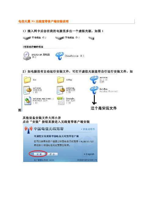
1)插入网卡后会在我的电脑里多出一个虚拟光驱,如图1
2)如电脑没有自动运行安装文件,可打开虚拟光驱盘符自行运行安装文件,如
图
其他设备安装文件大同小异
点击“安装”按钮直接进入无线宽带客户端安装
注:此过程根据您的电脑配置不同,可能会持续几分钟,请耐心等待
3)进入协议条款界面,您必须选择“我同意,我接受以上协议的所有条款”,才能进入下一步安装
4)默认勾选“进行快速安装”,选择此项,将客户端直接安装在默认路径下
5)单击<下一步>按钮,继续安装过程。
6)进入客户端安装过程
7)进入上网卡安装界面
在此安装期间,XP系统会弹出的发现新硬件窗口不用去点击任何按钮,系统会自动安装,WIN7系统会弹出让您选择停止安装驱动和始终进行安装驱动的对话框,请选择始终安装。
剩下的都是自动安装。
8)安装完毕,出现如下界面,由于某些上网卡驱动程序安装后要求重启计算机后才能正常使用,所以建议您选择“是,立即重新启动计算机”选项,并单击<完成>按钮,完成无线宽带客户端的安装。
9)安装完成后的界面
注意事项:2G用户只能连接最下面1X连接,如点自动连接或中间3G连接会产生额外费用导致上网卡欠费停用,后果自负.
程序卸载
1)点击开始→程序→无线宽带→卸载
2)去掉前面小对号如图
点确定完成卸载,卸载完如需重装驱动,需重启电脑再安装驱动
联通
根据电脑的语言选择后,下一步
根据电脑的系统会有1-2分钟的安装延迟,耐心等待
其它上网冲浪就和我们平时有线的一样哟,如果开始上网速度有些慢,就点击"断开"然后再连接上,这样。
无线路由器设置指南5-Client模式
无线路由器设置指南5-Client模式TP-LINK Mini系列无线路由器是真正做到即插即用的无线路由器。
出差或旅行途中入住酒店,只需要把酒店房间里提供的网线插到设备的以太网口,再把它插到电源插座上,整个房间就实现了Wi-Fi无线覆盖。
此时,您便可以拿出笔记本、Wi-Fi手机、iPad或是其它任何支持Wi-Fi无线上网的设备,在房间任何地方无线上网。
同时TP-LINK Mini系列无线路由器具有多种无线模式,无线组网灵活方便。
本文适用的产品包括:TL-WR700N、TL-WR702N、TL-WR706N、TL-WR710N、TL-WR800N。
(说明:TL-WR706N与TL-WR700N设置完全相同,唯一的区别是TL-WR706N增加了一个硬件模式开关,所以设置TL-WR706N时,首先只需要将硬件拨动到AP模式,其余设置方法可以完全参照本文)如果您使用的迷你路由器是TL-WR703N、TL-MR11U,请查看以下链接中的Client模式:/detail_article_209.html如果您使用的迷你路由器为TL-WR720N,设置方法与TL-WR703N设置方法一致,只需将TL-WR720N的硬件开关拨动到AP模式,然后登陆界面,参照以下链接文档中的Client模式设置即可:/detail_article_209.html下面就以TL-WR700N为例介绍其设置方法。
TL-WR700N的Client客户端模式,也称“主从模式”。
在此模式下工作的AP对于主AP来说是无线客户端,相当于无线网卡。
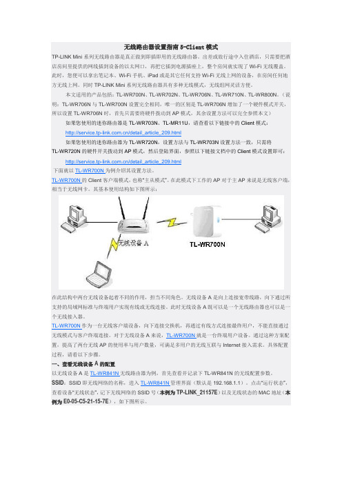
其基本使用结构如下图所示:在此结构中两台无线设备起着不同的作用,担当不同角色。
无线设备A是向上连接宽带线路,向下通过所支持的局域网标准与终端用户实现有线或无线连接。
此时无线设备A既可以是一个无线路由器也可以是一个无线接入器。
TL-WR700N作为一台无线客户端设备,向下连接交换机,再通过有线方式连接最终用户,不能直接通过无线模式与客户终端连接。
TP-LINK 工业级双频无线客户端 用户手册说明书

工业级双频无线客户端用户手册1910041163 REV1.0.0声明Copyright © 2023 普联技术有限公司版权所有,保留所有权利未经普联技术有限公司明确书面许可,任何单位或个人不得擅自仿制、复制、誊抄或转译本手册部分或全部内容,且不得以营利为目的进行任何方式(电子、影印、录制等)的传播。
为普联技术有限公司注册商标。
本手册提及的所有商标,由各自所有人拥有。
本手册所提到的产品规格和资讯仅供参考,如有内容更新,恕不另行通知。
除非有特殊约定,本手册仅作为使用指导,所作陈述均不构成任何形式的担保。
目录第1章用户手册简介 ............................... .. (1)1.1目标读者 (1)1.2本书约定 (1)第2章设备管理 ...................................... .. (2)2.1产品简介 (2)2.1.1Client (2)2.1.2Client-Router (4)2.2Web界面管理 (4)2.2.1登录前准备 (4)2.2.2登录Web管理界面 (5)2.2.3快速设置 (6)2.2.4首页 (9)第3章无线 ............................................. (10)3.1无线设置 (10)3.2无线热点 (11)3.3增强漫游 (11)3.4高级设置 (12)3.5无线冗余 (13)3.5.1配置参数 (14)3.5.2配置步骤 (14)第4章网络 ............................................. (17)4.1接口设置 (17)4.1.1功能介绍 (17)4.1.2配置方法 (18)4.2WAN设置 (18)4.2.1上网方式 (18)4.2.2高级设置 (19)4.3LAN设置 (19)4.3.1DHCP服务器 (20)4.3.2静态地址分配 (20)4.4静态路由 (21)4.4.1配置参数 (21)4.4.2静态路由配置实例 (21)4.5NAT (23)4.5.1功能介绍 (23)4.5.2配置方法 (23)4.5.3端口转发配置实例 (25)第5章串口 ............................................. (26)5.1工作模式 (26)5.1.1TCP-Server (26)5.1.2TCP-Client (27)5.1.3UDP (27)5.2通讯参数 (28)5.3串口日志 (28)5.4串口配置指南 (29)第6章系统 ............................................. (34)6.1工作模式 (34)6.2设备管理 (34)6.2.1Client模式 (34)6.2.2Client-Router模式 (35)6.3管理账号 (35)6.4系统日志 (36)6.5时间设置 (37)6.6配置管理 (37)6.7软件升级 (38)6.7.1在线软件升级 (38)6.7.2软件升级 (39)6.8Ping看门狗 (39)6.8.1配置参数 (39)6.8.2Ping看门狗配置指南 (40)6.9SSH服务器 (41)第1章 用户手册简介本手册旨在帮助用户正确使用工业级双频无线客户端,以TL-CPE1300D工业级为例进行介绍。
wireless客户端配置手册
公司北京办公室无线办公网接入使用手册
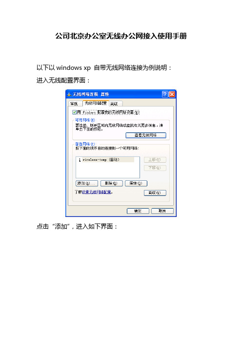
以下以windows xp 自带无线网络连接为例说明:
进入无线配置界面:
点击“添加”,进入如下界面:
在“网络名”中输入“wireless-OA”;
在“网络身份验证”中选择“WPA”方式;
在“数据加密”中选择“TKIP”加密方式。
点击上图中的“验证”菜单,弹出如下界面:
在“EAP类型”中选择“受保护的EAP(PEAP)”方式,然后点击右面的“属性”菜单,弹出如下界面:
首先取消掉“验证服务器证书”复选框;
点击右下方的“配置”菜单,弹出如下界面:
取消掉上图中的复选框,点击“确定”按键,然后按照出现的图中依次点击三次“确定”按键即可。
然后在无线网络界面中双击“wireless-OA”进行无线网络连接,界面如下:
然后会在右下方出现如下提示:
点击上面的图标,出现如下界面:
在“用户名”输入对应的用户名;
在“密码”中输入对应的密码;
点击“确定”后过一分钟左右会出现如下连接正常的显示:
至此完成无线连接的配置。
用户名: infotech (小写)
密码: 365BFB1C28 (大写)。
无线网络摄像机手机客户端功能说明书
手机客户端
说明书
目录:
1.安装手机客户端软件
2.客户端菜单介绍
3. 手机客户端添加设备
4. 手机客户端视频界面功能键
5. 手机客户端功能设置
5.1 WIFI设置
5.2 Ftp设置
5.3用户设置
5.4设置报警服务:移动侦测报警
5.5邮件设置
5.6 SD卡设置
5.7设备时钟设置
首先手机要保持上网状态(WIFI/3G )
支持版本苹果系统4.3以上/安卓系统2.2以上
1. 安装手机客户端软件
安卓APP :扫描彩盒或者说明书上的二维码进行下载并安装。
苹果APP :扫描彩盒或者说明书上的二维码进行下载并安装。
2.客户端菜单介绍
3. 手机客户端添加设备
部的二维码来添加摄像
或者手动输入摄像机网内可以点击“搜索”按钮来添加摄,摄像机出厂默认用户名,默认密码为空,如有加密,摄像机列表显示,点击选择
所需观看的摄像机,连接观看视频。
4.手机客户端视频界面功能键:
5.手机客户端功能设置:
5.1 WIFI设置:
5.2 Ftp设置:
5.3 用户设置:
5.4 设置报警服务:移动侦测报警
5.5邮件设置:
该功能是邮件报警功能,和报警功能同时设置使用,报警功能里需勾选。
摄像机接入互联网后才有此功能。
5.6 SD 卡设置:
5.7 设备时钟设置:。
无线客户端功能介绍

无线客户端介绍
1、菜单管理
用户可以点击主操作界面最上面的菜单栏,选择不同的操作项目进行操作。
打开主操作界面,各设置内容的含义如下图所示:
图1
2、设备控制
点击菜单栏上设备控制按钮,即可出现下图所示的下拉菜单,点击开机或关机按钮即可对大屏幕进行相对应的操作。
图2
3、预案管理
生成预案:用户将需要显示的图像信号在系统界面上开窗显示、并调整好相应位置后,可以将此种显示方案做为信号源预案保存,使用时只需调用该预案即可。
如需删除预案,在预案列表中选中相应的的预案点击鼠标右键,点击删除预案菜单即可。
执行预案:操作员在预案列表中用鼠标双击某一预案名即可执行该预案。
或选择一个预案名后击鼠标右键,打开快捷菜单选择执行该预案。
图3
4、信号源操作
用户对输入系统的视频信号、RGB信号、网络PC信号进行设置与管理。
包括:新增、修改、删除管理。
图4
用户在无线客户端的操作界面上拖动鼠标就可开出一个信号窗口。
点击信号源列表中相应的信号源,设置以“任意位置开窗”或“以单元为单位”开窗。
图5
5、无线客户端应用APP 下载
大屏幕控制系统支持无线客户端,支持安卓版、IOS版PAD的应用APP,通过无线客户端,可以便捷的操作控制大屏幕,包括信号切换、删除、上屏、开关机等。
软件下载界面截图如下:
图6。
无线模式说明
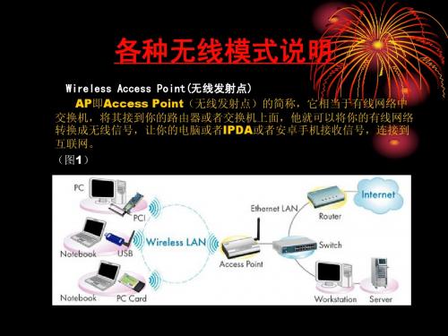
•
(无线网桥或者多点桥 无线网桥或者多点桥) Wireless Bridge (无线网桥或者多点桥) 这种模式下,可以多个无线AP相互连接起来!组成1个可以互访的局域网, AP相互连接起来 这种模式下,可以多个无线AP相互连接起来!组成1个可以互访的局域网, 每个AP后面可以加装交换机等设备!方便多机使用!工作在Bridge AP后面可以加装交换机等设备 Bridge模式下的设 每个AP后面可以加装交换机等设备!方便多机使用!工作在Bridge模式下的设 用无线网卡搜索不到其发射的无线信号。 备 用无线网卡搜索不到其发射的无线信号。 (图3):
•
(无线中继 无线中继) Wireless Repeater (无线中继) 无线中继器” 模式可以实现信号的中继和放大, Wireless Repeater “无线中继器” 模式可以实现信号的中继和放大, 无线中继器 从而延伸无线网络的覆盖范围。 AP之间可以通过设定MAC地址来互相连接 之间可以通过设定MAC地址来互相连接。 从而延伸无线网络的覆盖范围。各AP之间可以通过设定MAC地址来互相连接。 当两个局域网络间的距离超过无线局域网产品所允许的最大传输距离, 当两个局域网络间的距离超过无线局域网产品所允许的最大传输距离,或者 在两个网络之间有较高、较大干扰的障碍物存在时, 在两个网络之间有较高、较大干扰的障碍物存在时,便可以采用无线中继方 案来扩展无线网络覆盖。工作在Repeater模式下的设备 LAN口一般就没数据 案来扩展无线网络覆盖。工作在Repeater模式下的设备 LAN口一般就没数据 Repeater 输出了。 输户端) Wireless AP Client (无线客户端) 无线客户端)它相当于带有RJ45口的无线网卡, RJ45口的无线网卡 Wireless AP Client (无线客户端)它相当于带有RJ45口的无线网卡,可 以接收无线路由或者无线AP发射出来的信号,并将它转换为有线信号输出! AP发射出来的信号 以接收无线路由或者无线AP发射出来的信号,并将它转换为有线信号输出! 后 面加个交换机或者HUB 可为多台网络设备提供数据交换。工作在Client Client模式下 面加个交换机或者HUB 可为多台网络设备提供数据交换。工作在Client模式下 是不会向外发射无线信号的。 的设备是接收无线信号 是不会向外发射无线信号的。 (图2)
毛家2016年7月AWK-1127无线网络客户端说明书

P/N: 1802011270012 *1802011270012*AWK-1127Quick Installation GuideMoxa AirWorksEdition 2.0, July 2016Technical Support Contact Information/supportMoxa Americas:Toll-free: 1-888-669-2872 Tel: 1-714-528-6777 Fax: 1-714-528-6778 Moxa China (Shanghai office): Toll-free: 800-820-5036 Tel: +86-21-5258-9955 Fax: +86-21-5258-5505 Moxa Europe:Tel: +49-89-3 70 03 99-0 Fax: +49-89-3 70 03 99-99 Moxa Asia-Pacific:Tel: +886-2-8919-1230 Fax: +886-2-8919-1231 Moxa India:Tel: +91-80-4172-9088 Fax: +91-80-4132-10452016 Moxa Inc. All rights reserved.OverviewMoxa’s AWK-1127 WLAN client is ideal for applications that are hard to wire, too expensive to wire, or use mobile equipment that connects over a TCP/IP network. The AWK-1127 is rated to operate at temperatures ranging from 0 to 60°C for standard models and -40 to 75°C for extended temperature models, and is rugged enough for any harsh industrial environment. Installation is easy, with either DIN-rail mounting or distribution boxes. The DIN-rail mounting ability, wide operating temperature range, and IP30 housing with LED indicators make the AWK-1127 a convenient yet reliable solution for any industrial wireless application.Package ChecklistMoxa’s AWK-1127 is shipped with the following items. If any of these items is missing or damaged, please contact your customer service representative for assistance.• 1 AWK-1127• 2 dBi dual band antenna•Console protective cap•Resistive Terminator•Document and software CD•Quick Installation Guide (printed)•Warranty cardPanel Layout of the AWK-1127 Top Panel ViewFront Panel View Rear Panel View1.Grounding screw (M3)2.Terminal block for PWR1 andPWR23.RS-232 console port4.AUX antenna port5.System LEDs: PWR, FAULT, andSTATE LEDs6.LEDs for signal strength7.WLAN and LAN LEDs8.10/100BaseT(X) RJ45 Port9.MAIN antenna port10.RS-232/422/485 Serial port11.Screw hole for wall-mounting kit12.DIN-rail mounting kit13.Reset buttonMounting Dimensions (unit = mm)DIN-Rail MountingThe aluminum DIN-rail attachment plate should be fixed to the back panel of the AWK-1127 when you take it out of the box. If you need to reattach the DIN-rail attachment plate to the AWK-1127, make sure the stiff metal spring is situated towards the top, as shown in the figures below. STEP 1: Insert the top of the DIN rail into the slot just below the stiff metal spring.STEP 2: The DIN-rail attachment unit will snap into place as shown below.To remove the AWK-1127 from the DIN rail, simply reverse Steps 1 and 2.Wall Mounting (optional)For some applications, it may be more convenient to mount theAWK-1127 to a wall, as illustrated below:STEP 1:Remove the aluminumDIN-rail attachment platefrom the AWK-1127, andthen attach the wall mountplates with M3 screws, asshown in the adjacentdiagrams.STEP 2:Mounting the AWK-1127 to a wall requires 4 screws.Use the AWK-1127 device, with wall mount platesattached, as a guide to mark the correct locations ofthe 4 screws. The heads of the screws should be lessthan 6.0 mm in diameter, and the shafts should be lessthan 3.5 mm in diameter, as shown in the figure at theright.Do not drive the screws in all the way into the wall—leave a space of about 2 mm to allow room for sliding the wall-mount panel between the wall and the screws.NOTE Test the screw head and shank size by inserting the screws into one of the keyhole shaped apertures of the wall-mounting platesbefore attaching the plate to the wall.STEP 3:Once the screws are fixed into thewall, insert the four screw headsthrough the large opening of thekeyhole-shaped apertures, andthen slide the AWK-1127downwards, as indicated to theright. Tighten the four screws foradded stability.Wiring RequirementsYou should also pay attention to the following items:•Use separate paths to route wiring for power and devices. If power wiring and device wiring paths must cross, make sure the wires are perpendicular at the intersection point.NOTE Do not run signal or communications wiring and power wiring in the same wire conduit. To avoid interference, wires with differentsignal characteristics should be routed separately. note contenthere.•You can use the type of signal transmitted through a wire to determine which wires should be kept separate. The rule of thumb is that wiring with similar electrical characteristics can be bundledtogether.•Keep input wiring and output wiring separate.•It is strongly advised that you label wiring to all devices in the system when necessary.Grounding the Moxa AWK-1127Grounding and wire routing help limit the effects of noise due toelectromagnetic interference (EMI). Run the ground connection from the ground screw to the grounding surface prior to connecting devices.Installations with Unstable Power InputsThere are cases where the device has to be wired to the same power source as other equipment. In such cases if equipment such as motors that are connected in the circuit draw a large amount of current during operation, the transient voltage drop could potentially cause the AWK to become unstable. Installing a DC/DC power isolator in between the two equipment is recommended to isolate the transient effect and to ensure a stable power input for the AWK.Installations with Cable Extended Antennas for Outdoor ApplicationsIf the antenna or the AWK device is installed outdoors or in an open-air setting, proper lightning protection is required to prevent direct lightning strikes on the AWK device. In order to prevent coupling currents from nearby lightning strikes, a lightning arrester should be installed as part of your antenna system. Ground the device, antenna, as well as the arrester properly to provide maximum outdoor protection for the device.Arrester Accessories • SA-NMNF-01: Surge arrester, N-type (male) to N-type (female) •SA-NFNF-01: Surge arrester, N-type (female) to N-type (female)Wiring the Redundant Power InputsThe 4-contact terminal block connector on the AWK-1127’s top panel is used for the AWK-1127’s two DC inputs. The top and front views of the terminal block connector are shown here.Top ViewFront ViewSTEP 1: Insert the negative/positive DC wires into the V-/V+ terminals.STEP 2: To keep the DC wires from pulling loose, use a small flat-blade screwdriver to tighten the wire-clamp screws on the front of the terminal block connector.STEP 3: Insert the plastic terminal block connector prongs into the terminal blockreceptor, which is located on the AWK-1127’s top panel.Communication Connections10/100BaseT(X) Ethernet Port ConnectionThe 10/100BaseT(X) ports located on the AWK-1127’s front panel are used to connect to Ethernet-enabled devices.Below we show pinouts for both MDI (NIC-type) ports and MDI-X (HUB/Switch-type) ports.MDI Port Pinouts MDI-X Port Pinouts 8-pin RJ45Pin Signal Pin Signal1 Tx+ 1 Rx+2 Tx- 2 Rx-3 Rx+ 3 Tx+ 6Rx-6Tx-RS-232/422/485 Serial PortThe AWK-1127 has 1 RS-232/422/485 serial port with DB9 connector for serial to WLAN connectivity. Below are the pin assignments are the serial port. Pin RS-232 RS-422/485(4W) RS-485 (2W) 1 DCD TxD-(A) – 2 RxD TxD+(B) –3 TxD RxD+(B) Data+(B)4 DTR RxD-(A) Data-(A)5 GND GND GND6 DSR – –7 RTS – –8 CTS – – 9–––RS-232 Console ConnectionThe AWK-1127 has one RS-232 (8-pin RJ45) console port located on the top panel. Use either an RJ45-to-DB9 or RJ45-to-DB25 cable to connect the Moxa AWK-1127’s console port to your PC’s COM port. You may then use a console terminal program to access the AWK-1127 for console configuration.Console Pinouts for 10-pin or 8-pin RJ4510-PinDescription8-Pin 1 – 2 DSR 1 3 RTS 2 4 GND 3 5 TxD 4 6 RxD 5 7 DCD 6 8 CTS 7 9 DTR 8 10–NOTE1. The pin numbers for male DB9 and DB25 connectors, andhole numbers for female DB9 and DB25 connectors are labeled on the connector. However, the numbers aretypically quite small, so you may need to use a magnifying glass to see the numbers clearly.2. The pin numbers for both 8-pin and 10-pin RJ45 connectors(and ports) are typically not labeled on the connector (or port). Refer to the pinout diagram above for details.LED IndicatorsThe front panel of the Moxa AWK-1127 contains several LED indicators. The function of each LED is described in the table below.LED Color State DescriptionPWR Green On Power is on.Off Power is not being suppliedFAULT RedOn System is booting upBlinking(slow at1-secondintervals)Cannot get an IP address from theDHCP server.Blinking(fast at0.5-secondinterval)IP address conflict.Off Status is normal.STATE Green/RedGreenSystem startup is complete and thesystem is in operation.Green(Blinking at1-secondintervals)The device has been located by theWireless Search Utility.Red System is booting up.SIGNAL(5 LEDs) Green On Signal level Off ReservedWLAN GreenOn WLAN has been established. Blinking WLAN is transmitting data. Off WLAN is not working properly.LAN GreenOn 100/10 Mbps LAN port is active. Blinking Data is being transmitted.Off 100/10 Mbps LAN port is inactive.TX/RX GreenOn Serial port is transmitting data.OffNo data is being received through theserial port.AmberOn Serial port is receiving data.OffNo data is being transmitted throughthe serial port.SpecificationsWLAN InterfaceStandards IEEE 802.11a/b/g for Wireless LANIEEE 802.11i for Wireless SecurityIEEE 802.3 for 10BaseTIEEE 802.3u for 100BaseT(X)IEEE 802.3af for Power-over-Ethernet (PoE modelsOnly)IEEE 802.1D for Spanning Tree ProtocolIEEE 802.1w for Rapid STPSpread Spectrum and Modulation (typical) DSSS with DBPSK, DQPSK, CCKOFDM with BPSK, QPSK, 16QAM, 64QAM802.11b:CCK @ 11/5.5 Mbps, DQPSK @ 2 MbpsDBPSK @ 1 Mbps802.11a/g:64QAM @ 54/48 Mbps, 16QAM @ 36/24 Mbps QPSK @ 18/12 Mbps, BPSK @ 9/6 MbpsOperating Channels (central frequency) US:2.412 to 2.462 GHz (11 channels)5.18 to 5.24 GHz (4 channels)EU:2.412 to 2.472 GHz (13 channels)5.18 to 5.24 GHz (4 channels)JP:2.412 to 2.472 GHz (13 channels, OFDM)2.412 to 2.484 GHz (14 channels, DSSS)5.18 to 5.24 GHz (4 channels for W52)Security Firewall for MAC/IP/Protocol/Port-based filtering64-bit and 128-bit WEP encryption,WPA/WPA2-Personal and Enterprise (IEEE802.1X/RADIUS, TKIP, and AES)Transmission Rates 802.11b: 1, 2, 5.5, 11 Mbps802.11a/g: 6, 9, 12, 18, 24, 36, 48, 54 MbpsTX Transmit Power 802.11b:Typ. 18±1.5 dBm @ 1 to 11 Mbps802.11g:Typ. 18±1.5 dBm @ 6 to 24 MbpsTyp. 17±1.5 dBm @ 36 MbpsTyp. 16±1.5 dBm @ 48 MbpsTyp. 16±1.5 dBm @ 54 Mbps802.11a:Typ. 18±1.5 dBm @ 6 to 24 MbpsTyp. 16±1.5 dBm @ 36 MbpsTyp. 15±1.5 dBm @ 48 MbpsTyp. 14±1.5 dBm @ 54 MbpsRX Sensitivity 802.11b:-97 dBm @ 1 Mbps, -94 dBm @ 2 Mbps**************,-90dBm@11Mbps802.11g:-88 dBm @ 6 to 24 Mbps, -85 dBm @ 36 Mbps-75 dBm @ 48 Mbps, -70 dBm @ 54 Mbps802.11a:-88 dBm @ 6 to 24 Mbps, -85 dBm @ 36 Mbps-75 dBm @ 48 Mbps, -70 dBm @ 54 Mbps Protocol SupportGeneral Protocols Proxy ARP, DNS, HTTP, HTTPS, IP, ICMP, SNTP, TCP,UDP, RADIUS, SNMP, PPPoE, DHCPInterfaceDefault Antennas 1 dual-band omni-directional antennas, 2 dBi,RP-SMA (male)Connector forExternal AntennasRP-SMA (female)Serial Port 1, RS232/422/485, DB9 male connectorRJ45 Ports 1, 10/100BaseT(X) auto negotiation speed, F/Hduplex mode, and auto MDI/MDI-X connection Console Port RS-232 (RJ45-type)Reset PresentLED Indicators PWR, FAULT, STATE, SIGNAL, WLAN, LAN, TX, RX Serial Communication ParametersData Bits 5, 6, 7, 8Stop Bits 1, 1.5, 2Parity None, Even, Odd, Space, MarkFlow Control RTS/CTS, XON/XOFFBaudrate 50 bps to 921.6 kbpsSerial Data Log 256 KBSerial SignalsRS-232 DSR, RTS, GND, TxD, RxD, DCD, CTS, DTRRS-422 Tx+, Tx-, Rx+, Rx-, GNDRS-485 (2-wire) Data+, Data-, and GNDRS-485 (4-wire) Tx+, Rx+, Tx-, Rx+, and GNDPhysical CharacteristicsHousing Metal, providing IP30 protectionWeight 400 g (0.9 lb)Dimensions 50 x 115 x 70 mm(1.98 x 4.53 x 2.76 in) Installation DIN-rail mounting, wall mounting (with optional kit) Environmental LimitsOperating Temperature Standard Models: 0 to 60°C (32 to 140°F) Wide Temp. Models: -40 to 75°C (-40 to 167°F)StorageTemperature-40 to 85°C (-40 to 185°F)Ambient RelativeHumidity5% to 95% (non-condensing)Power RequirementsInput Voltage 12 to 48 VDC, redundant dual DC power inputs or 48VDC Power-over-Ethernet (IEEE 802.3afcompliant)**PoE is only available for the AWK-1127-PoE Connector 4-pin removable terminal blockPower Consumption 12 to 48 VDC, 0.16 to 0.55 AReverse PolarityProtectionPresentStandards and CertificationsSafety UL 60950-1, EN 60950-1EMC EN 301 489-1/17; FCC Part 15, Subpart B; EN55022/55024Radio EN 300 328, EN 301 893, TELEC, FCC IDSLE-WAPN003Note: Please check Moxa’s website for the most up-to-date certification status.ReliabilityMTBF 392,209 hrs.WarrantyWarranty Period 5 yearsDetails See /support/warranty.aspxNOTE For installation flexibility, either the MAIN antenna (on the front panel) or the AUX antenna (on the top panel) may be selected foruse. Make sure the antenna connection matches the antennaconfigured in the AWK-1127 web interface.To protect the connectors and RF module, all radio ports shouldbe terminated by either an antenna or a terminator. We stronglyrecommend using resistive terminators for terminating theunused antenna ports.NOTE。
MOXA无线配置(AP、客户端)
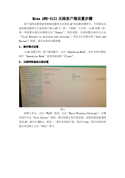
Moxa AWK-3121无线客户端设置步骤客户端的设置登陆和基础设置的方法参看AP的设置步骤即可。
不同的是无线参数设置的几个选项客户端与AP不一样,下面做一下介绍。
与AP设置一样,每一项设置完成以后都要点击“Submit”,保存设置。
全部设置完成以后点击“Click Restart to activate new settings”,然后点击页面中的“Save and Restart”按钮,重启并保存设置参数。
1、操作模式设置
与AP设置不同,客户端设置中,点击“Operation Mode”,在打开的右侧页面中“Operation Mode”选项里就选择“Client”。
2、无线网络基础无线设置
图1
如图1所示,点击“WLAN”选项,点击“Basic Wireless Settings”,右侧页面中点击“Site Survey”按钮,弹出如图2所示的页面,如果是要连接调度室的AP,就点中DDS-1,要是一二期大车的客户端,就点中bm1,然后在弹出的提示对话框上点击“确定”即可。
图2
3、无线网络安全设置
图3
如图2所示,点击“WLAN Security Settings”(无线安全设置),参数就按照如图所示设置。
“Passphrase”选项里输入密码:0315*******。
Advanced Wireless Settings与Ap设置一样,不再作叙述。
aigo无线硬盘客户端软件使用说明V3.1

爱国者无线硬盘 客户端软件使用说明V3.1目录免责声明 (3)特别提示: (4)一、设备的准备与连接 (4)1.1开机 (4)1.2 WiFi信号的连接 (4)1.2.1 Windows 平台 (4)1.2.2 iOS 平台 (5)1.2.3 Android 平台 (8)1.3移动网络存储服务器(移动NAS)模式 (12)二、客户端软件的安装 (13)2.1 Windows 平台 (13)2.2 iOS 平台 (14)2.3 Android 平台 (14)三、Windows客户端软件的界面说明 (17)四、iOS、Android客户端软件的界面说明 (18)4.1登录设备 (18)4.2 DLNA目录 (20)4.3文件播放 (22)4.3.1视频播放 (22)4.3.2音乐播放 (23)4.3.3图片浏览 (24)4.3.4文档浏览 (24)4.3.5 DLNA推送 (25)4.3.6 AirPlay功能 (26)4.4文件管理 (27)4.4.1分享按钮 (29)4.4.2操作按钮 (30)4.4.3传输按钮 (33)4.5设置界面 (35)4.5.1设备设置 (36)4.5.1.1无线设置 (36)4.5.1.2局域网设置 (38)4.5.1.3互联网设置 (39)4.5.1.4系统设置 (43)4.5.2来宾用户 (45)4.5.3缓存设置 (46)4.5.4语言设置 (46)4.5.5关于 (47)4.5.6注销 (47)五、使用第三方软件进行访问 (48)由于产品的更新,本手册中的图片和文字可能与您的设备中显示的图文略有不同,某些细微的变更将不会影响您的操作,请以实物操作为主。
一、感谢您购买爱国者无线硬盘产品。
在使用本产品之前,请认真阅读快速使用说明和本说明书。
当您开始使用爱国者无线硬盘产品时,爱国者电子认为您已经认真阅读了本说明书。
二、本产品为移动存储产品,用于用户数据的冗余备份,请用户在使用过程中及时对其中的数据进行备份。
无线客户端说明

无线客户端说明答使用业务之前,用户需要做好如下准备:(1)在PC上安装客户端软件。
(2)并将UIM卡插入数据卡,将数据卡连接PC(不连接天翼网络无需该操作)。
(3)打开PC上的WLAN接入设备,并在客户端软件设置无线宽带(WLAN)接入帐号(不连接无线宽带(WLAN)无需该操作)。
(4)假如需要连接其他无线网络,请打开PC上的WLAN设备。
无线宽带客户端涉及什么帐号,如何获得?答涉及下列帐号::(1)无线宽带(WLAN)帐号:申请无线宽带后获得,CDMA手机用户使用现有CDMA手机号码,我的e 家用户使用现有e家帐号,其他情况中国电信会为用户提供一个天翼号码。
所需密码均在套装中的密码信封内。
该帐号用于登录电信公共热点WLAN,即以“ChinaNet”为名的无线网络。
(2)天翼帐号:申请时套装内的UIM卡内置了天翼(CDMA)网络的认证信息,接入号、接入密码等已经预先在客户端软件中设定了。
(3)其他无线帐号:为接入其他无线网络的帐号,其认证方式视具体接入的网络而定,由布放该网络的机构或者组织掌控。
如何安装客户端软件?答:有两种方式:为什么我的客户端安装过程特别慢?答:可能与您的系统性能有关,是正常现象,请您耐心等待,系统性能较低的可能原因是:(1)系统CPU处理能力低或者内存容量少(2)系统运行的应用程序较多导致系统性能下降(3)系统安装的杀毒软件在侦测安装程序是否含有病毒我的机器是Windows98,为什么不能安装?答:中国电信中文版PC客户端软件目前仅支持Windows2000中文版,Windows XP中文版与Vista中文版,不支持Windows95、98与非中文操作系统。
UIM卡有何用处?答:UIM记录了用户连接天翼网络的认证信息。
如何安装UIM卡?答用户按照数据卡说明书的指示,将UIM卡装入数据卡即可。
:如何安装数据卡驱动?答有下列两种方式::(1)安装光盘内有套装中对应型号数据卡的安装程序,选择完全安装即可自动安装该驱动程序,用户也可选择仅安装数据卡驱动程序,只安装相应数据卡驱动。
- 1、下载文档前请自行甄别文档内容的完整性,平台不提供额外的编辑、内容补充、找答案等附加服务。
- 2、"仅部分预览"的文档,不可在线预览部分如存在完整性等问题,可反馈申请退款(可完整预览的文档不适用该条件!)。
- 3、如文档侵犯您的权益,请联系客服反馈,我们会尽快为您处理(人工客服工作时间:9:00-18:30)。
使用前要作哪些准备?答使用业务之前,用户需要做好如下准备:(1)在PC上安装客户端软件。
(2)并将UIM卡插入数据卡,将数据卡连接PC(不连接天翼网络无需该操作)。
(3)打开PC上的WLAN接入设备,并在客户端软件设置无线宽带(WLAN)接入帐号(不连接无线宽带(WLAN)无需该操作)。
(4)如果需要连接其他无线网络,请打开PC上的WLAN设备。
无线宽带客户端涉及哪些帐号,如何获得?答涉及以下帐号::(1)无线宽带(WLAN)帐号:申请无线宽带后获得,CDMA手机用户使用现有CDMA手机号码,我的e 家用户使用现有e家帐号,其他情况中国电信会为用户提供一个天翼号码。
所需密码均在套装中的密码信封内。
该帐号用于登录电信公共热点WLAN,即以“ChinaNet”为名的无线网络。
(2)天翼帐号:申请时套装内的UIM卡内置了天翼(CDMA)网络的认证信息,接入号、接入密码等已经预先在客户端软件中设定了。
(3)其他无线帐号:为接入其他无线网络的帐号,其认证方式视具体接入的网络而定,由布放该网络的机构或组织掌控。
答:有两种方式:为什么我的客户端安装过程特别慢?答:可能和您的系统性能有关,是正常现象,请您耐心等待,系统性能较低的可能原因是:(1)系统CPU处理能力低或内存容量少(2)系统运行的应用程序较多导致系统性能下降(3)系统安装的杀毒软件在侦测安装程序是否含有病毒我的机器是Windows98,为什么不能安装?答:中国电信中文版PC客户端软件目前仅支持Windows2000中文版,Windows XP中文版和Vista中文版,不支持Windows95、98以及非中文操作系统。
UIM卡有何用处?答:UIM记录了用户连接天翼网络的认证信息。
答用户按照数据卡说明书的指示,将UIM卡装入数据卡即可。
:如何安装数据卡驱动?答有以下两种方式::(1)安装光盘内有套装中对应型号数据卡的安装程序,选择完全安装即可自动安装该驱动程序,用户也可选择仅安装数据卡驱动程序,只安装相应数据卡驱动。
(2)用户也可以通过客户端软件中的菜单,设置->数据卡驱动管理->下载数据卡驱动,选择相应型号的数据卡驱动,下载并安装。
(3)用户可直接到网上营业厅、互联星空下载安装驱动。
如何连接数据卡?答按照数据卡说明书,将数据卡连接PC相应硬件端口即可。
:我可以从主界面知道哪些信息?答打开客户端软件,用户可以了解相应网络的信号强度信息。
如果打开客户端软件时用户PC已处在网络:连接状态,客户端将显示当前网络连接状态。
没有数据卡时,我能使用其他网络连接吗?答:没有数据卡,用户仍然能够通过客户端软件连接无线宽带(WLAN)、和其他无线网络,仅天翼CDMA 网络无法接入。
我原来的数据卡还能用吗?答:无线宽带业务需要使用符合中国电信标准,通过中国电信认证过的数据卡设备,原有数据卡无法适应无线宽带业务,但可使用原有的客户端连接中国电信天翼网络。
我在市场上买的数据卡能用吗?答:无线宽带业务需要使用符合中国电信标准,通过中国电信认证过的数据卡设备,其他型号数据卡无法适应无线宽带业务,但可能可以使用自带的客户端连接中国电信天翼网络。
无线宽带(WLAN)接入无线宽带(WLAN)是什么?答:无线宽带(WLAN)指中国电信在公共热点地区布设的,以“ChinaNet”为名的无线宽带网络。
连接无线宽带(WLAN)网络需要哪些条件?答:需要以下条件:(1)用户开通无线宽带业务。
(2)用户没有欠费停机。
(3)正确安装并启动客户端软件。
(4)客户端软件上配置了无线宽带(WLAN)接入帐号(如果事先没有配置,连接过程中将提示用户设置)。
(5)用户打开了PC上的无线接入设备。
(6)环境中具有以“ChinaNet”为名的无线网络信号。
如何连接无线宽带(WLAN)网络?答:您只需点击客户端主界面上无线宽带(WLAN)标签后的连接按钮,客户端将自动为您接入无线宽带(WLAN)网络。
如果您没有事先设置帐号与密码,连接过程中会提示您输入并保存。
为什么我连接不上无线宽带(WLAN)网络?答:可能有以下原因:(1)PC上的WLAN设备没有打开解决:打开PC上的WLAN设备(2)环境中没有以“ChinaNet”为名的无线网络信号解决:请在有“ChinaNet”为名的无线信号环境使用该功能,主界面有无线宽带(WLAN)信号强度提示(3)没有设置无线宽带(WLAN)接入帐号或者设置错误解决:请通过客户端菜单设置->上网帐号设置->无线宽带(WLAN)帐号设置进行正确设置(4)帐号欠费停机解决:请充值并复机后使用有其他接入无线宽带(WLAN)网络的方法吗?答:您也可以通过中国电信无线宽带Portal登录中国电信WLAN,当您的PC连上以“ChinaNet”为名的无线网络,获得IP地址,此时打开浏览器,输入任意网址,将自动跳转到登录业务,按页面指示输入帐号、密码、开户地等信息,即可登录并连接上Internet。
我使用客户端无法在电信热点漫游上网答:您无法上网的原因可能是您使用的帐号不支持全国漫游。
天翼(CDMA)接入天翼(CDMA)是什么?答天翼(CDMA)是中国电信布设的公共无线通信网络。
:哪里有天翼(CDMA)?答天翼(CDMA)为公共覆盖,基本都有信号。
:连接天翼(CDMA)网络需要哪些条件?答需要以下条件::(1)用户开通无线宽带业务。
(2)用户没有欠费停机。
(3)正确安装并启动客户端软件。
(4)PC上正确安装了数据卡驱动。
(5)用户在数据卡中正确安装UIM卡,数据卡正确连接PC。
(6)环境中具有天翼(CDMA)网络信号。
如何连接天翼(CDMA)网络?答您只需点击客户端主界面上天翼标签后的连接按钮,客户端将自动为您接入天翼(CDMA)网络。
:为什么我连接不上天翼网络?答可能有以下原因:(1)没有正确插入UIM卡解决:请在数据卡内正确插入UIM卡(2)PC没有正确连接数据卡解决:按照正确方式将数据卡与PC连接(3)环境中没有天翼(CDMA)网络信号解决:请在有天翼网络信号的环境使用该功能,主界面有天翼信号强度提示(4)CDMA接入号与密码设置错误解决:请通过客户端菜单设置->上网帐号设置->天翼帐号设置检查接入号码与密码是否正确,接入号为#777,用户名为ctnet@,密码为vnet.mobi,客户端初始已设置(5)欠费停机解决:请充值并复机后使用信号弱不稳定,经常连接不上网络?答可能有以下原因:(1)数据卡天线没有拉出来解决:完全拉出天线(2)当地信号不稳定解决:换个地方试试,客户端主界面上会提示网络信号强度(3)客户端软件版本比较老解决:升级客户端软件到最新版本(4)无线上网卡硬件问题解决:更换数据卡试试。
天翼上网过程中经常出现断线?答可能有以下原因:(1)一般情况是由于传输线路质量不好,易出现杂波干扰数据通讯解决:换个地方试试,客户端主界面上会提示网络信号强度(2)天线接触不良;解决:检查天线是否正常(3)天翼(CDMA)信号较弱,由于信号衰减易形成断线;解决:换个地方试试,客户端主界面上会提示网络信号强度我更换了数据卡,如何安装新的驱动?答有两种方式::(1)您可以使用购买数据卡时附带的驱动安装程序自行安装。
(2)您可以通过客户端菜单设置->数据卡驱动管理->下载数据卡驱动,选择相应的数据卡型号,下载并安装驱动。
(3)用户可直接到网上营业厅、互联星空下载安装驱动。
注:您必须使用符合中国电信标准并通过中国电信认证的数据卡。
如何卸载我电脑上已经安装的数据卡驱动?答您可以通过客户端菜单设置->数据卡驱动管理->删除数据卡驱动,选择相应的数据卡型号,删除驱动。
:我的客户端运行时电脑无法休眠?答可能是由于数据卡底层驱动占用内存,建议把客户端关闭后再进行休眠。
:其他无线接入其他无线是什么?答其他无线指非中国电信部署的无线宽带信号。
:哪里有其他无线?答其他非中国电信机构或组织部署了无线宽带信号的地区。
:连接其他无线网络需要哪些条件?答需要以下条件::(1)正确安装并启动客户端软件。
(2)客户端软件上配置了其他无线接入帐号(如果事先没有配置,连接过程中将提示用户设置)。
(3)用户打开了PC上的无线接入设备。
(4)环境中具有其他无线网络信号。
如何连接其他无线网络?答有两种方式::您只需点击客户端主界面上其他无线标签后的搜索按钮,客户端将提供您当前环境内所有其他无线网络列表,您可以选择其中一个网络信号点击连接,自动为您接入相应的其他无线网络。
为什么我不能接入其他无线网络?答:可能有以下原因:(1)PC上的WLAN设备没有打开解决:打开PC上的WLAN设备(2)环境中没有以其他无线网络信号解决:请在有其他无线信号环境使用该功能,主界面有其他无线网络信号强度提示(3)没有相应网络的认证帐号解决:请联系布设相应网络的机构或组织,申请接入帐号PIN码管理什么是PIN码?答:PIN码是UIM卡的个人识别密码。
如果未经使用者修改,运营商设置的原始密码是1234。
如果启用PIN 码保护,那么每次启动客户端后就要输入4位数PIN码,PIN码是可以修改的,用来保护自己的UIM卡不被他人使用。
需要注意的是,如果输入三次PIN码错误,便会自动锁卡,并提示输入PUK码解锁,这个时候已经接近了危险的边缘,因此,如果擅自修改了PIN码,一定要牢记。
什么是PUK码?答:PUK码由8位数字组成,用户无法更改的。
当手机PIN码被锁,并提示输入PUK码时,输入正确的PUK 码即可解锁。
如何启用和禁止PIN码保护功能答:通过客户端菜单中的启用PIN码保护或禁止PIN码保护,用户启用或禁用PIN码保护功能,使用该两项功能的时候,要输入当前PIN码。
如何知道我UIM卡的PIN码和PUK码?答:初始PIN码为1234,当您UIM卡被锁死后,请致电中国电信客服,查询相应的PUK码。
启用了PIN码保护功能,有什么作用?答:启用了PIN码保护,您必须在启动客户端时输入正确的PIN码,才能使用CDMA上网和CDMA应用。
启用PIN码保护,能够保护您的UIM卡不被人盗用。
如何使用PIN码修改功能?答:通过客户端菜单中的PIN码修改功能,可以修改PIN码,修改时需要先输入当前PIN码,并输入两次完全一样的新PIN码。
如何使用PIN码验证功能?答:通过客户端菜单中的PIN码验证功能,输入PIN码,验证PIN码是否正确。
如何使用PUK码解锁功能?答:当您的UIM卡被PIN码锁住(连续三次输入PIN码错误),您可以通过客户端菜单中的PUK解锁功能,输入正确的PUK码进行解锁,同时设定新的PIN码,注意,PUK码10次错误输入将彻底锁住UIM卡。
为什么PIN正确,但还是不能用?答:可能是因为您已连续输入三次错误的PIN码,UIM卡被锁了。
