WSLP2512
常用三极管参数大全
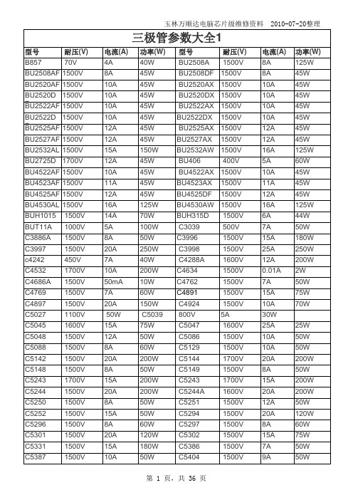
玉林万顺达电脑芯片级维修资料 2010-07-20整理玉林万顺达电脑芯片级维修资料 2010-07-20整理玉林万顺达电脑芯片级维修资料 2010-07-20整理玉林万顺达电脑芯片级维修资料 2010-07-20整理玉林万顺达电脑芯片级维修资料 2010-07-20整理玉林万顺达电脑芯片级维修资料 2010-07-20整理玉林万顺达电脑芯片级维修资料 2010-07-20整理玉林万顺达电脑芯片级维修资料 2010-07-20整理玉林万顺达电脑芯片级维修资料 2010-07-20整理玉林万顺达电脑芯片级维修资料 2010-07-20整理玉林万顺达电脑芯片级维修资料 2010-07-20整理玉林万顺达电脑芯片级维修资料 2010-07-20整理玉林万顺达电脑芯片级维修资料 2010-07-20整理玉林万顺达电脑芯片级维修资料 2010-07-20整理玉林万顺达电脑芯片级维修资料 2010-07-20整理玉林万顺达电脑芯片级维修资料 2010-07-20整理玉林万顺达电脑芯片级维修资料 2010-07-20整理玉林万顺达电脑芯片级维修资料 2010-07-20整理玉林万顺达电脑芯片级维修资料 2010-07-20整理玉林万顺达电脑芯片级维修资料 2010-07-20整理玉林万顺达电脑芯片级维修资料 2010-07-20整理玉林万顺达电脑芯片级维修资料 2010-07-20整理玉林万顺达电脑芯片级维修资料 2010-07-20整理玉林万顺达电脑芯片级维修资料 2010-07-20整理玉林万顺达电脑芯片级维修资料 2010-07-20整理玉林万顺达电脑芯片级维修资料 2010-07-20整理玉林万顺达电脑芯片级维修资料 2010-07-20整理玉林万顺达电脑芯片级维修资料 2010-07-20整理玉林万顺达电脑芯片级维修资料 2010-07-20整理玉林万顺达电脑芯片级维修资料 2010-07-20整理。
WSL2512R0270FEA18;WSL25125L000FEA18;WSL0805R0250FEA18;WSL0805R1000FEA18;中文规格书,Datasheet资料

STANDARD ELECTRICAL SPECIFICATIONS
GLOBAL MODEL SIZE POWER RATING P70 °C W 0.20 0.25 0.5 1.0 2.0 RESISTANCE VALUE RANGE Tol. ± 0.5 % Tol. ± 1.0 % 0.01 to 0.1 0.01 to 0.1 0.005 to 0.2 0.005 to 0.2 0.005 to 0.2 0.001 to 0.2 0.004 to 0.5 0.001 to 0.5 0.003 to 0.04 0.0005 to 0.04 WEIGHT (typical) g/1000 pieces 1.9 4.8 16.2 38.9 63.6
PACKAGING CODE EA = Lead (Pb)-free, tape/reel EK = Lead (Pb)-free, bulk TA = Tin/lead, tape/reel (R86) TG = Tin/lead, tape/reel (RT1, for WSL0603 and WSL0805) BA = Tin/lead, bulk (B43)
WSL0603...18 0603 WSL0805...18 0805 WSL1206...18 1206 WSL2010...18 2010 WSL2512...18 2512 Note • Part marking: Value; tolerance: Due to resistor size limitations some resistors will be marked with only the resistanceer
DIMENSIONS in inches (millimeters)
LM3409HV评估板

EN引脚PWM调光(上升沿): 20kHz, 50%占空比
30093544
外部FET,PWM调光: 100kHz,50%占空比
30093547
30093548
外部FET,PWM调光(上升沿): 100kHz,50%占空比
最小模拟调光(VADJ = 0V)
30093545
7
最大模拟调光(VADJ 悬空)
LM3409HV 评估板
LM3409HV 评估板
美国国家半导体公司 应用注释1953 James Patterson 2009年6月11日
介绍
此评估板用来演示降压型电流调节器LM3409HV PFET 控制器。此设计是在直流输入电压48V时可驱动12个LED (VO=42V),LED的最大平均电流为1.5A。典型的开关频率 为400KHz,但开关频率在整个工作范围内会发生变化。此 电路可接受6~75V输入电压,但如果输入电压低于LED串电 压,变换器就会进入低压降工作模式,理想情况下VO=VIN。
1. 标称开关频率
假定C7=470pF,η=0.97,可得R6:
由步骤2可得L1:
3. LED 平均电流
计算IL-MAX: 假定VADJ=1.24V,可得R9: 最接近此值,精度为1%的电阻为0.15Ω,因此ILED为:
由步骤3可得:
最接近此阻值,精度为1%的电阻为16.5 kΩ,因此实际 tOFF与目标fSW为:
上拉电阻,如果低于5V的PWM信号加在PWM2上,R3确保 CMOS门极被上拉到5V。旁路电容C5选择0.1µF。
方法#3:去掉端子J1上的跳线,使用EN引脚进行内部 PWM调光。外部PWM信号加在EN端可以提供PWM调光。
典型波形图部分列出使用两种PWM调光时的典型LED电 流波形。
abb工业机器人协同动作应用手册

Robotics Products Se-721 68 Västerås
瑞典
目表
目表
手册概述 ............................................................................................................................................. 7 产品文档,IRC5 ................................................................................................................................. 9 安全 .................................................................................................................................................... 11
应用手册 MultiMove
Trace back information: Workspace R15-2 version a20 Checked in 2015-10-22 Skribenta version 4.6.176
应用手册 MultiMove
RobotWare 6.02 文档编号: 3HAC050961-010
3.2.1 Controller参数域集合 ................................................................................ 30 3.2.2 Motion参数域集合 .................................................................................... 32 3.2.3 I/O参数域集合 ......................................................................................... 33 3.3 配置示例 .......................................................................................................... 34 3.3.1 “UnsyncArc”的配置示例 ............................................................................ 34 3.3.2 “SyncArc”的配置示例 ............................................................................... 36 3.3.3 输入/输出配置示例 ................................................................................... 38
常用场效应管(25N120等)参数及代换ai

常用场效应管(25N120等)参数及代换FGA25N120AND (IGBT)1200V/25A//TO3P (电磁炉用)FQA27N25 (MOSFET)250V/27A/TO3P IRFP254FQA40N25 (MOSFET)250V/40A/280W/0.051Ω/TO3P IRFP264FQA55N25 (MOSFET)250V/55A/310W/0.03Ω/TO3PFQA18N50V2 (MOSFET)500V/20A/277W/0.225Ω IRFP460AFQA24N50 (MOSFET)500V/24A/290W/0.2Ω/TO3PFQA28N50 (MOSFET)500V/28.4A/310W/0.126Ω/TO3P MTY30N50EFQL40N50 (MOSFET)500V/40A/560W/0.085Ω/TO264 IRFPS37N50FQA24N60 (MOSFET)600V/24A/TO3PFQA10N80 (MOSFET)800V/9.8A/240W/0.81Ω/TO3PFQA13N80 (MOSFET)800V/13A/300W/0. Ω/TO3PFQA5N90 (MOSFET)900V/5.8A/185W/2.3Ω/TO3PFQA9N90C (MOSFET)900V/8.6A/240W/1.3Ω/TO3PFQA11N90C (MOSFET)900V/11.4A/300W/0.75Ω/TO3PFFA30U20DN (快恢复二极管)200V/2×30A/40ns/TO3P DSEK60-02AFFPF30U60S (快恢复二极管)600V/30A/90ns/TO220F MUR1560FFA30U60DN (快恢复二极管)600V/2×30A/90ns/TO3P DSEK60-06AMBRP3010NTU (肖特基)100V/30A/TO-220MBRA3045NTU (肖特基)45V/30A/TO-3PISL9R3060G2 (快恢复二极管)600V/30A/35ns/200W/TO247 APT30D60BRHRG3060 (快恢复二极管)600V/30A/35nS/TO247FQP44N10 (MOSFET)100V/44A/146W/0.0396Ω/TO220 IRF3710/IRF540NFQP70N10 (MOSFET)100V/57A/160W/0.025Ω/TO220IRFP450B (MOSFET)500V/14A/0.4Ω/205W/TO3PIRFP460C (MOSFET)500V/20A/0.2~0.24Ω/235W IRFP460KA3162/FAN8800 (Drive IC)单IGBT/MOSFETFET驱动ICRHRP860 (快恢复二极管)600V/8A/30NS/TO-220 MUR860RHRP1560 (快恢复二极管)600V/15A/TO0220 MUR1560RHRP8120 (快恢复二极管)1200V/8A/75W/TO220RHRP15120 (快恢复二极管)1200V/15A/TO220RHRP30120 (快恢复二极管)1200V/30A/125W/TO220单DSEI20-10ARHRG30120 (快恢复二极管)1200V/30A/T03PSSH45N20B (MOSFET)200V/45A/TO3P IRFP260FGL40N150D (IGBT)1500V/40A/TO264快速IGBTFGL60N100BNTD (IGBT)1000V/60A/TO264快速IGBT 1MBH60-100HGTG10N120BND (IGBT)1200V/35A/298W/100ns/TO247HGTG11N120CND (IGBT)1200V/43A/298W/TO247HGTG18N120BND (IGBT)1200V/54A/390W/90ns/TO247FQP5N50C (MOSFET)500V/5A/73W/1.4Ω/TO-220 替代:IRF830,用于35WFQPF5N50C (MOSFET)500V/5A/38W/1.4Ω/TO-220F 替代:IRF830,用于35W FQP9N50C (MOSFET)500V/9A/135W/0.6Ω/TO220 替代:IRF840,用于75W FQPF9N50C (MOSFET)500V/9A/44W/0.6Ω/TO-220F 替代:IRF840,用于75W FQP13N50 (MOSFET)500V/13.4A/190W/0.43Ω/TO220 用于75W/125W产品FQPF13N50 (MOSFET)500V/13.4A/48W/0.43Ω/TO220F 用于75W/125W产品FQD5N50C (MOSFET)500V/5A/1.4Ω/TO252 用于35W FQA16N50 (MOSFET)500V/16A/200W/0.32C/TO3P 用于150W到250W的产品FDP15N50 (MOSFET)500V/15A/0.43Ω/56W/TO220 用于150W左右的产品FQP18N50V2 (MOSFET)500V/18A/0.43Ω/208W/TO220 用于250WG到400W的产品FQPF18N50V2 (MOSFET)500V/18A/0.43Ω/56W/TO220 用于250WG到400W的产品FQA18N50V2 (MOSFET)500V/20A/277W/0.225Ω/TO3P 用于250WG到400W的产品FQA24N50 (MOSFET)500V/24A/290W/0.2Ω/TO3P 用于400W的产品FQA24N60 (MOSFET)600V/23.5A/310W/0.24Ω/TO3P 用于400W的产品FQA28N50 (MOSFET)500V/28.4A/310W/0.126Ω/TO3P 用于400W的产品FQL40N50 (MOSFET)500V/40A/560W/0.085Ω/TO264 用于560W的产品IRF740B (MOSFET)400V/10A/0.55Ω/134W/TO220IRF730B (MOSFET)400V/5.5A/1.0Ω/73W/TO220IRF830B (MOSFET)500V/4.5A/1.5Ω/73W/TO220IRF840B (MOSFET)500V/8A/0.85Ω/134W/TO220IRFP450B (MOSFET)500V/14A/0.4Ω/205W/TO3PIRFP460C (MOSFET)500V/20A/0.2~0.24Ω/235WFQPF5N60C (MOSFET)600V/5A/TO220FFQPF8N60C (MOSFET)600V/8A/TO220FFQPF10N60C (MOSFET)600V/10A/TO220FQPF12N60 (MOSFET)600V/12A/51W/0.65Ω/TO220FFCP11N60 (MOSFET)650V/11A/125W0.32Ω/TO220RHRD660S (快恢复二极管)600V/6A/TO-252RHRP860 (快恢复二极管)600V/8A/75W/TO-220RHRP1560 (快恢复二极管)600V/15A/TO-220单2N7002 (三极管)60V/0.12A/SOT-23 HUF76629D3S (MOSFET)100V/20A/110W/TO-252HUF75639S3S (MOSFET)100V/56A/200W/TO-263ISL9V3040D3S (IGBT)430V/21A/150W/300MJ/TO252ISL9V3040S3S (IGBT)430V/21A/150W/300MJ/TO263ISL9V5036S3S (IGBT)360V/46A/250W/TO262FQP33N10L (MOSFET)100V/33A/52MΩ127W/TO220。
东芝DP1608.2008.2508中文维修手册_部分1
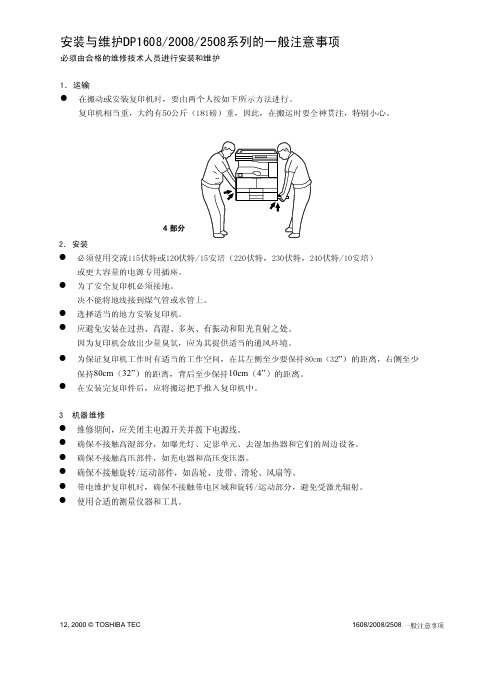
7 14 17
6 8 9
!
A3-A5-R FOLIO LD-ST-R COM
64-80g/m
17-21 lbs
-
-
A3-A5-R FOLIO LD-ST-R COM
64-80g/m 17-21 lbs 80-163g/m 21-43 lbs
OHP /
1608/2008/2508
2 - 15
1608/2008/2508
5
CL 1 RGST-CLT
B-1
CL 2
OCF-CLT
B-1
CL 3
PU-CLT
B-3
6
THM 1 FUS-THM
D-1
THM 2 HEA1-THM
D-1
1
THM 3 HEA2 THM
D-1
2
THM 4 SCN-THM
DБайду номын сангаас2
1
ASD/AUD/CND//SAD
FUS
PWA-F-FUS
AC
PWA
A-1
PWA
ACD/AUD/CND/D/SAD
12, 2000 © TOSHIBA TEC
2 - 17
1608/2008/2508
2.4
2.4.1
2.4.2
PFU PFP ADU SFB OCT
1608/2008/2508
2 - 18
10, 2000 © TOSHIBA TEC
PFP
16
16
16
-
12
12
12
-
13
13
13
-
11
11
11
2012培训教材-轻中卡操纵部分解析

3
2012年培训教材
2012年培训教材
轻卡变速器操纵部分大致相同(见图1),不同的地 方在于使用不同变速器时所用的软轴固定支架、软轴及挡 位标牌不同,见表1。
4
2012年培训教材
2012年培训教材
图1
5
2012年培训教材
变速器型号 HW20505TCL HW24505TCL 布置型式 变速器左操纵 变速器左操纵 变速器左操纵 HW25505TCL 变速器右操纵 软轴 选LG9704240010(2400) 手柄 LG9704240026 LG9704240003 LG9704240003 LG9704240002 软轴支架 LG9704240032 LG9704240032 LG9704240011 LG9704240019
2012年培训教材
2012年培训教材
轻型卡车变速器操纵部分结构简介
技术中心 2012年2月
2012年培训教材
2012年培训教材
2012年培训教材
2012年培训教材
目前我公司轻卡系列车型变速器操纵采用双软轴操纵, 该结构布置方便,结构简单,便于模块化装配。 通过优化设计,合理布置软轴走向,支架结构简单,重 量轻。 挡位清晰,换选挡力度适中。
2012年培训教材
26
2012年培训教材
2012年培训教材
图7
27
2012年培训教材
(6)软轴及气管走向与固定
2012年培训教材
轻卡系列车型使用的软轴最小转弯半径为200mm,因此
在固定软轴时要避免软轴直径小于200mm。软轴使用扎带固 定,避免和其他运动部件磨碰、干涉,尽可能远离排气管。 装HW50508C变速器时气管顺着软轴进入驾驶室,和软轴捆绑 在一起。
WSLS2512, 改进稳定性说明书
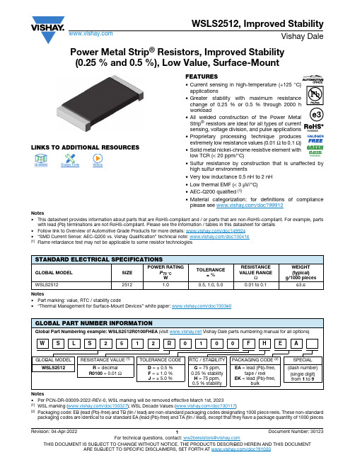
Power Metal Strip® Resistors, Improved Stability (0.25 % and 0.5 %), Low Value, Surface-MountLINKS TO ADDITIONAL RESOURCES FEATURES •Current sensing in high-temperature (+125 °C)applications•Greater stability with maximum resistancechange of 0.25 % or 0.5 % through 2000 hworkload•All welded construction of the Power MetalStrip® resistors are ideal for all types of currentsensing, voltage division, and pulse applications•Proprietary processing technique producesextremely low resistance values (0.01 Ω to 0.1 Ω)•Solid metal nickel-chrome resistive element withlow TCR (< 20 ppm/°C)•Sulfur resistance by construction that is unaffected byhigh sulfur environments•Very low inductance 0.5 nH to 2 nH•Low thermal EMF (< 3 μV/°C)•AEC-Q200 qualified (1)•Material categorization: for definitions of complianceplease see /doc?99912Notes•This datasheet provides information about parts that are RoHS-compliant and / or parts that are non-RoHS-compliant. For example, parts with lead (Pb) terminations are not RoHS-compliant. Please see the information / tables in this datasheet for details•Follow link to Overview of Automotive Grade Products for more details: /doc?49924•“SMD Current Sense: AEC-Q200 vs. Vishay Qualification” technical note: /doc?30416(1)Flame retardance test may not be applicable to some resistor technologiesNotes•Part marking: value, RTC / stability code•“Thermal Management for Surface-Mount Devices” white paper: /doc?30380Notes•Per PCN-DR-00009-2022-REV-0, WSL marking will be removed effective March 1st, 2023(1)WSL marking (/doc?30327); WSL Decade Values (/doc?30117)(2)Packaging code: EB (lead (Pb)-free) and TB (tin / lead) are non-standard packaging codes designating 1000 piece reels. These non-standardpackaging codes are identical to our standard EA (lead (Pb)-free) and TA (tin / lead), except that they have a package quantity of 1000 pieces 3D3D3D ModelsAvailableAvailableSTANDARD ELECTRICAL SPECIFICATIONSGLOBAL MODEL SIZEPOWER RATINGP70 °CWTOLERANCE± %RESISTANCEVALUE RANGEΩWEIGHT(typical)g/1000 pieces WSLS25122512 1.00.5, 1.0, 5.00.01 to 0.163.6GLOBAL PART NUMBER INFORMATIONGlobal Part Numbering example: WSLS2512R0100FHEA (visit Vishay Dale parts numbering manual for all options)GLOBAL MODEL RESISTANCE VALUE (1)TOLERANCE CODE RTC / STABILITY PACKAGING CODE (2)SPECIAL WSLS2512R = decimalR0100 = 0.01 ΩD = ± 0.5 %F = ± 1.0 %J = ± 5.0 %G = 75 ppm,0.25 % stabilityH = 75 ppm,0.5 % stabilityEA = lead (Pb)-free,tape / reelEK = lead (Pb)-free,bulk(dash number)(single digit)from 1 to 9 S L S2512R0100F H W E ANotes•“Temperature Coefficient of Resistance for Current Sensing” white paper: /doc?30405(1)Component TCR - total TCR that includes the TCR effects of the resistor element and the copper terminal(2)Element TCR - only applies to the alloy used for the resistor element; refer to item 1 in the construction illustration on the following page (3)Maximum working voltage - the WSL is not voltage sensitive, but is limited by power / energy dissipation and is also not ESD sensitiveDIMENSIONS in inches (millimeters)Notes•3D models available: /doc?30306•Surface-mount solder profile recommendations: /doc?31052WELDED CONSTRUCTION 2512DERATINGTECHNICAL SPECIFICATIONSPARAMETERUNIT RESISTOR CHARACTERISTICSComponent temperature coefficient (including terminal) (1)ppm/°C ± 75Element TCR (2)ppm/°C < 20Operating temperature range °C -65 to +170Maximum working voltage (3)V(P x R )1/2MODEL DIMENSIONSSOLDER PAD DIMENSIONSL W H Ta b l WSLS25120.250 ± 0.010(6.35 ± 0.254)0.125 ± 0.010(3.18 ± 0.254)0.025 ± 0.010(0.635 ± 0.254)0.030 ± 0.010(0.762 ± 0.254)0.065(1.65)0.145(3.68)0.160(4.06)1) Re s i s tive element:s olid metal nickel-chrome or mangane s e-copper alloy re s i s tive element with low TCR (< 20 ppm/°C)2) Plated terminal3) Terminal / element weld4) S ilicone coating with ink print231470120100806040200170150125100755025-25-50-65Ambient Temperature in °CR a t e d P o w e r i n %PERFORMANCETESTCONDITIONS OF TESTTEST LIMITS 0.25 %0.5 %Thermal shock -55 °C to +150 °C, 1000 cycles, 15 min at each extreme ± 0.5 % + 0.005 ΩShort time overload 5 x rated power for 5 s for WSL2512 size or smaller ± 0.5 % + 0.005 ΩLow temperature operation -65 °C for 24h ± 0.5 % + 0.005 ΩHigh temperature exposure 1000 h at +170 °C± 1.0 % + 0.005 ΩBias humidity +85 °C, 85 % RH, 10 % bias, 1000 h ± 0.5 % + 0.005 ΩMechanical shock 100 g ’s for 6 ms, 5 pulses± 0.5 % + 0.005 ΩVibration Frequency varied 10 Hz to 2000 Hz in 1 min, 3 directions, 12 h ± 0.5 % + 0.005 ΩLoad life2000 h at 70 °C, 1.5 h “ON”, 0.5 h “OFF”± 0.25 %± 0.5 %Resistance to solder heat +260 °C solder, 10 s to 12 s dwell, 25 mm/s emergence ± 0.5 % + 0.005 ΩMoisture resistance MIL-STD-202, method 106, 0 % power, 7b not required± 0.5 % + 0.005 ΩNotes•Embossed carrier tape per EIA-481(1)Additional packaging details at /doc?20051PACKAGING (1)MODEL REELTAPE WIDTH DIAMETER PIECES/REELCODE WSLS251212 mm / embossed plastic178 mm / 7"2000EALegal Disclaimer Notice VishayDisclaimerALL PRODU CT, PRODU CT SPECIFICATIONS AND DATA ARE SU BJECT TO CHANGE WITHOU T NOTICE TO IMPROVE RELIABILITY, FUNCTION OR DESIGN OR OTHERWISE.Vishay Intertechnology, Inc., its affiliates, agents, and employees, and all persons acting on its or their behalf (collectively,“Vishay”), disclaim any and all liability for any errors, inaccuracies or incompleteness contained in any datasheet or in any other disclosure relating to any product.Vishay makes no warranty, representation or guarantee regarding the suitability of the products for any particular purpose or the continuing production of any product. To the maximum extent permitted by applicable law, Vishay disclaims (i) any and all liability arising out of the application or use of any product, (ii) any and all liability, including without limitation special, consequential or incidental damages, and (iii) any and all implied warranties, including warranties of fitness for particular purpose, non-infringement and merchantability.Statements regarding the suitability of products for certain types of applications are based on Vishay's knowledge of typical requirements that are often placed on Vishay products in generic applications. Such statements are not binding statements about the suitability of products for a particular application. It is the customer's responsibility to validate that a particular product with the properties described in the product specification is suitable for use in a particular application. Parameters provided in datasheets and / or specifications may vary in different applications and performance may vary over time. All operating parameters, including typical parameters, must be validated for each customer application by the customer's technical experts. Product specifications do not expand or otherwise modify Vishay's terms and conditions of purchase, including but not limited to the warranty expressed therein.Hyperlinks included in this datasheet may direct users to third-party websites. These links are provided as a convenience and for informational purposes only. Inclusion of these hyperlinks does not constitute an endorsement or an approval by Vishay of any of the products, services or opinions of the corporation, organization or individual associated with the third-party website. Vishay disclaims any and all liability and bears no responsibility for the accuracy, legality or content of the third-party website or for that of subsequent links.Except as expressly indicated in writing, Vishay products are not designed for use in medical, life-saving, or life-sustaining applications or for any other application in which the failure of the Vishay product could result in personal injury or death. Customers using or selling Vishay products not expressly indicated for use in such applications do so at their own risk. Please contact authorized Vishay personnel to obtain written terms and conditions regarding products designed for such applications. No license, express or implied, by estoppel or otherwise, to any intellectual property rights is granted by this document or by any conduct of Vishay. Product names and markings noted herein may be trademarks of their respective owners.© 2023 VISHAY INTERTECHNOLOGY, INC. ALL RIGHTS RESERVED。
惠威HR70遥控器使用说明书
HR070 Series Remote Control Programming Guide
6. Repeat steps 1 to 5 for the other components you want to control. For future reference, write down each working component code below:
HR Series Remote Control Programming
Assigned Push-button Component Program Code
TV
CBL
SAT
AUX
DVR
Push-buttons available for Programming
Flashes during Programming
4
Used to activate Programming Mode
with the most popular code first. If the component
responds, go to step 7.
6. If the component does not respond, press LEVEL+
Push-button and the Remote Control will test
The HR70 Series Remote Controls have stored in permanent memory the necessary information to send the correct commands to the component to be controlled. By entering a five digit numeric code the commands for controlling the component is activated.
电流检测最的三个最基础知识点电子教案

电流检测最的三个最基础知识点目前,电流检测的阻值非常低,其主要用于测量流经其山的电流。
通过该电阻的电流主要是通过电阻两端的电压反映出来,所以通过应用公式I=V/R该公式是由某著名学校的老师乔治·西蒙·欧姆提出的:即电阻上的电流与电压成正比。
上面简单的介绍就当作抛砖引玉了,本文的主题——电阻选择、高边或低边监测以及检测放大器的选择——都是以这个电气工程基本公式为基础的。
电流检测监控有助于提高一些系统的效率,减少损失。
例如,许多手机实现了电流检测监控,提高电池寿命,同时提高可靠性。
如果电流消耗太大,手机可以做出决定,降低CPU频率来减少电池负载以此延长电池寿命,同时防止手机过热来增加稳定性。
甚至有手机应用程序可以访问电流检测并且对优化手机的性能做出决策。
除了电流检测监控使用了一个电阻,另外两个不太常用的方法也使用了电阻。
其一是使用霍尔效应传感器来测量产生通量场的电流。
虽然这是非侵入性的,并且具有非插入损耗的优点。
它相对来说有点贵,并且要求一个相对大的PCB基板。
另一种方法,使用变压器测量感应的交流电流,也属于面积和成本密集型;并且同时只对交流电流有用。
本文将介绍使用一个电阻进行电流检测监控的三个基本方面:1、选择一个低阻值精度采样电阻。
如果说基板是基于“位置,位置,位置”,然而选择一个电阻就是基于“精度,精度,精度”原则。
2、选择一个检测放大器芯片。
当感应到在小于1欧姆电阻,电压很小的变化也会产生一个很大的结果。
检测放大器将电压变化放大,使无意义的事情变的更有意义。
3、检测电阻的“位置,位置,位置”。
这个若检测参考电源,称为高边检测,或者如果连接地,又叫作低边检测。
精密电流传感应用程序不再是自制食物电路;制造商已经做了所有的研究和现代设计的大部分工作。
电阻选择选择电阻值,精度和物理尺寸都取决于预期的电流测量值。
电阻值越大,测量可能就越精确,但大的电阻值也会导致更大的电流损失。
对于低功率电池驱动的设备,必须减少损失,电阻大约一毫米的长度值并且带有成百上千欧姆的电阻经常被使用。
MU70-SU0 LGA2011插座R3主板 用户手册说明书
2-3-6-1 IOAT 配置...................................................................................................84
-3-
第3章
2-3-2-3 CPU T State Control(CPU T 状态控制)............................................73
2-3-3 Common RefCode Configuration(通用 RefCode 配置)..............74
2-3-5-1 内存拓扑.....................................................................................................79
2-3-5-2 内存热效应................................................................................................80
目录
包装箱物品...........................................................................................................5 MU70-SU0 主板布局..........................................................................................6 框图.......................................................................................................................9 第 1 章 硬件安装.............................................................................................10
CJT长江连接器A2512系列

1.80±0.05
1.80±0.05
0.60±0.05
SEC:B-B
Ordering information & Specifications:
Part NO
Wire Range Insulation O.D.
A2512F-TP
AWG#22-#28 1.70mm(max)
A2512F-GP
AWG#22-#28 1.70mm(max)
A2512-T
2.50mm Pitch Crimp Terminal
Reference Informations:
*Used in CJT A2512HF series Housing
0.20
3.50±0.25
3.05±0.25
6.60±0.25 0.90
2.05 1.45 1.90±0.20
A
A
B
A2512 SERIES
2.50mm pitch wire to board connector
A2512WV
2.50mm pitch 180° Wafer
Reference Informations: *Material:Pin:Brass/Tin over Nickel
Insulator:Nylon 66 ,UL94V-0 *Mates with CJT A2512 series Housing *Color:White
Reference Informations: *Material:Pin:Brass/Tin over Nickel
Insulator:Nylon 66 ,UL94V-0 *Mates with CJT A2512 series Housing *Color:White
WSLS2512LDGEA中文资料

Improved Stability (0.25 % and 0.5 %), Power Metal Strip ® ResistorsLow Value (0.01 Ω to 0.1 Ω), Surface MountWSLS2512, Improved StabilityVishay Dale For technical questions, contact: ww2bresistors@Document Number: 30123FEATURES•Current sensing in high-temperature (+ 125 °C)applications•G reater stability with maximum resistance change of 0.25 % or 0.5 % through 2000 h workload•Ideal for all types of current sensing, voltage division and pulse applications including switching and linear power supplies,instruments, power amplifiers and shunts•Proprietary processing technique produces extremely low resistance values (0.01 Ω to 0.1 Ω)•All welded construction•Solid metal Nickel-Chrome resistive element with low TCR (< 20 ppm/°C)•Lead (Pb)-free construction is RoHS compliant •Very low inductance 0.5 nH to 2 nH•Excellent frequency response to 50 MHz •Low thermal EMF (< 3 µV/°C)Note•Part Marking: Value, RTC/Stability codeSTANDARD ELECTRICAL SPECIFICATIONSGLOBAL MODELPOWER RATINGP 70 °C WRESISTANCE RANGEΩWEIGHT (typical)g/1000 pieces± 1.0 %WSLS25121.00.01 - 0.163.6TECHNICAL SPECIFICATIONSPARAMETERUNIT WSLS2512 RESISTOR CHARACTERISTICSTemperature Coefficient ppm/°C ± 75Operating Temperature Range °C - 65 to + 170Maximum Working VoltageV(P × R )1/2GLOBAL PART NUMBER INFORMATIONNEW GLOBAL PART NUMBERING: WSLS2512R0100FHEAGLOBAL MODEL RESISTANCE VALUE TOLERANCE CODERTC/STABILITY PACKAGING CODE SPECIAL WSLS2512L = m Ω*R = Decimal 5L000 = 0.005 ΩR0100 = 0.01 Ω* use “L ” for resistance value< 0.01 ΩD = ± 0.5 %F = ± 1.0 %J = ± 5.0 %G = 75 ppm, 0.25 %stabilityH = 75 ppm, 0.5 %stabilityEA = Lead (Pb)-free,tape/reelEK = Lead (Pb)-free,bulk(Dash Number)(up to 2 digits)From 1 - 99 as applicableS L S 2512R 0W 100F H AEWSLS2512, Improved StabilityImproved Stability (0.25 % and 0.5 %),Power Metal Strip ® ResistorsLow Value (0.01 Ω to 0.1 Ω), Surface MountVishay DaleDocument Number: 30123For technical questions, contact: ww2bresistors@DIMENSIONSNote•Embossed Carrier Tape per EIA-481-2MODELDIMENSIONS in inches [millimeters]LWHTWSLS25120.250 ± 0.0100.125 ± 0.0100.025 ± 0.0100.030 ± 0.010[6.35 ± 0.254][3.18 ± 0.254][0.635 ± 0.254][0.762 ± 0.254]MODEL SOLDER PAD DIMENSIONS in inches [millimeters]a b l WSLS25120.0650.1450.160[1.65][3.68][4.06]PERFORMANCETESTCONDITIONS OF TESTTEST LIMITS 0.25 %0.5 %Thermal Shock - 55 °C to + 150 °C, 1000 cycles, 15 min at each extreme ± (0.5 % + 0.005 Ω) ΔR Short Time Overload 5 x rated power for 5 s for WSL2512 size or smaller ± (0.5 % + 0.005 Ω) ΔR Low Temperature Operation - 65 °C for 45 min ± (0.5 % + 0.005 Ω) ΔR High T emperature Exposure 1000 h at + 170 °C± (1.0 % + 0.005 Ω) ΔR Bias Humidity + 85 °C, 85 % RH, 10 % Bias, 1000 h ± (0.5 % + 0.005 Ω) ΔR Mechanical Shock 100 g’s for 6 ms, 5 pulses± (0.5 % + 0.005 Ω) ΔR Vibration Frequency varied 10 to 2000 Hz in 1 min, 3 directions, 12 h ± (0.5 % + 0.005 Ω) ΔR Load Life2000 h at 70 °C, 1.5 h “ON”, 0.5 h “OFF”± 0.25 % ΔR± 0.5 % ΔRResistance to Solder Heat + 260 °C Solder, 10 to 12 s dwell, 25 mm/s emergence ± (0.5 % + 0.005 Ω) ΔR Moisture ResistanceMIL-STD-202, Method 106, 0 % power, 7b not required± (0.5 % + 0.005 Ω) ΔRPACKAGINGMODEL REELTAPE WIDTH DIAMETER PIECES/REELCODE WSLS251212 mm/Embossed Plastic178 mm/7"2000EADisclaimer Legal Disclaimer NoticeVishayAll product specifications and data are subject to change without notice.Vishay Intertechnology, Inc., its affiliates, agents, and employees, and all persons acting on its or their behalf (collectively, “Vishay”), disclaim any and all liability for any errors, inaccuracies or incompleteness contained herein or in any other disclosure relating to any product.Vishay disclaims any and all liability arising out of the use or application of any product described herein or of any information provided herein to the maximum extent permitted by law. The product specifications do not expand or otherwise modify Vishay’s terms and conditions of purchase, including but not limited to the warranty expressed therein, which apply to these products.No license, express or implied, by estoppel or otherwise, to any intellectual property rights is granted by this document or by any conduct of Vishay.The products shown herein are not designed for use in medical, life-saving, or life-sustaining applications unless otherwise expressly indicated. Customers using or selling Vishay products not expressly indicated for use in such applications do so entirely at their own risk and agree to fully indemnify Vishay for any damages arising or resulting from such use or sale. Please contact authorized Vishay personnel to obtain written terms and conditions regarding products designed for such applications.Product names and markings noted herein may be trademarks of their respective owners.元器件交易网Document Number: 。
LINEAR LTC1422 数据手册
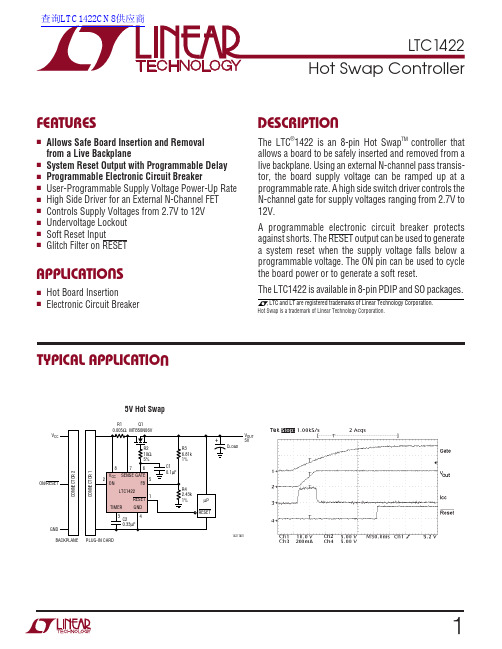
12LTC1422W U U PACKAGE/ORDER I FOR ATIOSupply Voltage (V CC )........................................... 13.2V Input Voltage (TIMER, SENSE)... –0.3V to (V CC + 0.3V)Input Voltage (FB, ON)........................... –0.3V to 13.2V Output Voltage (RESET)........................ –0.3V to 13.2V Output Voltage (GATE)............................. –0.3V to 20V Operating Temperature RangeLTC1422C ...............................................0°C to 70°C LTC1422I........................................... –40°C to 85°C Storage Temperature Range................ –65°C to 150°C Lead Temperature (Soldering, 10 sec)................. 300°CABSOLUTE AXI U RATINGSW W WU Consult factory for Military grade parts.ELECTRICAL CHARACTERISTICSThe q denotes the specifications which apply over the full operatingtemperature range, otherwise specifications are at T A = 25°C. V CC = 5V unless otherwise noted.(Note 1)Note 1: Absolute Maximum Ratings are those values beyond which the life of a device may be impaired.LTC142234LTC1422TYPICAL PERFOR A CE CHARACTERISTICSU WSUPPLY VOLTAGE (V)2T I M E R T H R E S H O L D V O L T A G E (V )1.2441.2421.2401.2381.2361.2341.232468101422 G101214TIMER Threshold Voltage vs Supply VoltageSUPPLY VOLTAGE (V)22.0T I M E R C U R R E N T (µA )2.12.22.32.42.6468101422 G1212142.5TIMER Current vs Supply VoltageTEMPERATURE (°C)–55T I M E R T H R E S H O L D V O L T A G E (V )651.2421.2411.2401.2391.2381.2371.2361.2351.2341.2331422 G115–358525–1510545125TIMER Threshold Voltage vs TemperatureON Pin Threshold Voltage vs Supply VoltageTIMER Current vs TemperatureTEMPERATURE (°C)–55T I M E R C U R R E N T (µA )652.452.402.352.302.252.202.152.102.052.001422 G135–358525–1510545125SUPPLY VOLTAGE (V)2O N P I N T H R E S H O L D V O L T A G E (V )1.321.301.281.261.241.221.20468101422 G141214ON Pin Threshold Voltage vs TemperatureTEMPERATURE (°C)–55O N P I N T H R E S H O L D V O L T A G E (V )651.381.361.341.321.301.281.261.241.221.201422 G155–358525–1510545125Current Limit Threshold vs TemperatureTEMPERATURE (°C)–5540C U R R E N T L I M I T T H R E S H O LD (m V )4555606565851422 G17505–358525–1510545125707580RESET Pull-Up Current vs TemperatureTEMPERATURE (°C)–554R E S E T P U L L -U P C U R R E N T (µA )610121465221422 G1885–358525–1510545125161820LTC142256LTC1422PI FU CTIO SU U UGATE (Pin 6): The high side gate drive for the external N-Channel. An internal charge pump guarantees at least 10V of gate drive. The slope of the voltage rise or fall at the GATE is set by an external capacitor connected between GATE and GND, and the 10µA charge pump output cur-rent. When the circuit breaker trips, the undervoltage lockout circuit monitoring V CC trips, or the ON pin is pulled low for more than 40µs, the GATE pin is immediately pulled to GND.SENSE (Pin 7) : Circuit Breaker Set Pin. With a sense resistor placed in the supply path between V CC and SENSE,the circuit breaker will trip when the voltage across the resistor exceeds 50mV for more than 10µs. If the circuit breaker trip current is set to twice the normal operating current, only 25mV is dropped across the sense resistor during normal operation. To disable the circuit breaker,V CC and SENSE can be shorted together.V CC (Pin 8): The positive supply input, ranging from 2.7V to 13.2V for normal operation. I CC is typically 0.6mA. An undervoltage lockout circuit disables the chip until the voltage at V CC is greater than 2.47V.FBRESETGNDV SENSEGATE TIMER1422 BDONBLOCK DIAGRAWLTC142278LTC1422APPLICATIO S I FOR ATIO W UU U V OUTTIMER RESETV2V2V2V1V11.232V1.232V12341422 F04Figure 4. Supply Monitor WaveformsWhen the voltage at the FB pin rises above its reset threshold (1.232V), the comparator COMP 2 output goeshigh, and a timing cycle starts (Figure 4, time points 1 and 4). After a complete timing cycle, RESET is pulled high.The 12µA pull-up current source to V CC on RESET has a series diode so the pin can be pulled above V CC by an external pull-up resistor without forcing current back into supply.When the supply voltage at the FB pin drops below its reset threshold, the comparator Comp 2 output goes low. After passing through a glitch filter, RESET is pulled low (time point 2). If the FB pin rises above the reset threshold for less than a timing cycle, the RESET output will remain low (time point 3).Glitch FilterThe LTC1422 has a glitch filter to prevent RESET from generating a system reset when there are transients on the FB pin . The filter is 20µs for large transients (greater than 150mV) and up to 80µs for small transients. The relation-ship between glitch filter time and the transient voltage is shown in Typical Performance curve: Glitch Filter Time vs Feedback Transient.Soft ResetIn some cases a system reset is desired without a power down. The ON pin can signal the RESET pin to go low without turning off the external N-channel (a soft reset).This is accomplished by holding the ON pin low for only 15µs or less (Figure 5, time point 1). At about 30µs from the falling edge of the ON pin (time point 2) the RESET pin goes low and stays low for one timing cycle.Figure 5. Soft Reset Waveforms1422 F05If the ON pin is held low for longer than 40µs, the gate will turn off and the RESET pin will eventually go low (time points 4, 5 and 6).TimerThe system timing for the LTC1422 is generated by the circuitry shown in Figure 6. The timer is used to set the turn-on delay after the ON pin goes high and the delay before the RESET pin goes high after the output supply voltage is good as sensed by the FB pin.OUT LOADFigure 6. System Timing Block DiagramLTC1422910LTC1422Q21/2 Si99436OUT OUT 5V OUT 3.3V OUTFigure 10. Switching 5V and 3.3VOUT Figure 9. ON Pin Circuitryand C3 are used to set the rise and fall delays on the 5V supply. Next, the 3.3V supply ramps up with a 20ms delay set by R6 and C2. On the falling edge, the 3.3V supply ramps down first because R6 is bypassed by the diode ing the LTC1422 as a Linear RegulatorThe LTC1422 can be used to Hot Swap the primary supply and generate a secondary low dropout regulated supply.Figure 11 shows how to switch a 5V supply and create a 3.3V supply using the reset comparator and one addi-tional transistor. The FB pin is used to monitor the 3.3V output. When the voltage on the gate of Q2 increases, the 3.3V increases. At the 3.3V threshold, the reset compara-tor will trip. The RESET pin goes high which turns on Q3.This lowers the voltage on the gate of Q2. This feedback loop is compensated by the capacitor C1 and the resistors R6 and R7.Hot Swapping 48V DC/DC Module with Active Low On/Off Control SignalUsing a 7.5V Zener and a resistor, the LTC1422 can switch supplies much greater than the 12V V CC pin rating. As shown in Figure 12, the switching FET Q1 is connected as a common source driver rather than the usual source follower used in previous applications. This allows the ground of the LTC1422 to sit at the negative terminal of the 48V input. The clamp circuit of R5 and D1 provides power to the LTC1422. The resistive divider R1 and R2 at the ON pin monitors the input supply. The switching FET Q1 is prevented from turning on until the input supply is at least 38V. Using the reset comparator to monitor the gate voltage allows the module to be turned on after the gate has reached a minimum level plus one timing cycle. A high to the module On/Off input.APPLICATIO S I FOR ATIO W UUU1112Power N-Channel and Sense Resistor Selection The decision of which external power N-Channel to use is dependent on its maximum current rating and the maxi-mum allowed current times R DS(ON) drop across the transistor. Table 1 lists some transistors that are available.Table 2 lists some current sense resistors that can be used with the circuit breaker. Since this information is subject to change, please verify the part numbers with the manufacturer. Table 3 lists the web sites of several manu-facturers.Table 1. N-Channel Selection GuideCURRENT LEVEL (A)PART NUMBER DESCRIPTION MANUFACTURER 0 to 2MMDF3N02HD Dual N-Channel SO-8ON Semiconductor R DS(ON) = 0.1Ω2 to 5MMSF5N02HD Single N-Channel SO-8ON Semiconductor R DS(ON) = 0.025Ω5 to 10MTB50N06V Single N-Channel DD Pak ON Semiconductor R DS(ON) = 0.028Ω10 to 20MTB75N05HDSingle N-Channel DD Pak ON SemiconductorR DS(ON) = 0.0095ΩTable 2. Sense Resistor Selection GuideCURRENT LIMIT VALUE PART NUMBER DESCRIPTIONMANUFACTURER 1A LR120601R0500.05Ω 0.25W 1% Resistor IRC-TT 2A LR120601R0250.025Ω 0.25W 1% Resistor IRC-TT 2.5A LR120601R0200.02Ω 0.25W 1% Resistor IRC-TT 3.3A WSL2512R015F 0.015Ω 1W 1% Resistor Vishay-Dale 5A LR120601R0100.01Ω 0.25W 1% Resistor IRC-TT 10AWSR2R005F0.005Ω 2W 1% ResistorVishay-DaleTable 3. Manufacturers’ Web SitesMANUFACTURER WEB SITE TEMIC Semiconductor International Rectifier ON Semiconductor Harris Semiconductor IRC-TT Vishay-DaleAPPLICATIO S I FOR ATIO W UU U1314Figure 15. Switching 48V to a Vicor Module with Isolated ControllerOPTIONALPRECHARGE RESISTORFigure 14. Hop Swapping Redundant 48V SuppliesOPTIONALPRECHARGE RESISTOR1422 F14APPLICATIO S I FOR ATIO W UU UInformation furnished by Linear Technology Corporation is believed to be accurate and reliable. However, no responsibility is assumed for its use. Linear Technology Corporation makes no represen-tation that the interconnection of its circuits as described herein will not infringe on existing patent rights.1516© LINEAR TECHNOLOGY CORPORA TION 19971422fa LT/TP 0300 2K REV A • PRINTED IN USATYPICAL APPLICATIO UPART NUMBER DESCRIPTION COMMENTS LTC1421Hot Swap Controller24-Pin Multiple Supplies LT1640L/LT1640H Negative Voltage Hot Swap Controller in SO-8Operates from –10V to –80V LT1641High Voltage Hot Swap Controller in SO-8Operates from 9V to 80VLT1642Fault Protected Hot Swap Controller Operates Up to 16.5V, Protected to 33V LTC1643L/LTC1643H PCI-Bus Hot Swap Controller 3.3V, 5V and ±12V in Narrow 16-Pin SSOP LT16452-Channel Hot Swap ControllerOperates from 1.2V to 12V, Power Sequencing LTC1647Dual Hot Swap Controller in SO-8 or SSOP-16Two ON Pins, Operates from 2.7V to 16.5VRELATED PARTS+–Figure 17. Switching 48V with Current SensingCurrent Sensing with 48V ApplicationsIn the LTC1422, the SENSE pin threshold is 50mV below the V CC pin. Typically, the current sense resistor is con-nected to the V CC pin, but in 48V applications the sense resistor is connected to the negative terminal of the 48V supply. The circuit in Figure 17 translates the current in the sense resistor to a resistor connected to the LTC1422SENSE pin.The voltage drop across the current sense resistor R SENSE is proportional to the load current I LOAD . The voltage drop across R SENSE is buffered by the op amp follower and is forced on R MIRROR .The mirror current can be described as: I MIRROR = I LOAD •R SENSE /R MIRROR . The mirror current flows through the trip resistor R TRIP . When the mirror current generates 50mV across R TRIP , the LTC1422 will latch the GATE pin low (50mV = I MIRROR • R TRIP = I LOAD • R SENSE /R MIRROR •R TRIP ). This example uses a 48V input but this translation circuit can be used anywhere the current sense resistor is not tied to V CC .Linear Technology Corporation1630 McCarthy Blvd., Milpitas, CA 95035-7417(408) 432-1900 q FAX: (408) 434-0507 q 。
2233-气腹机说明书

危险级别及其安全性的说明
标志 危险级别
严重警告! 不遵守此项将导致严重的身体伤害甚至死亡。 警告! 不遵守此项将导致轻微的身体伤害或者会损坏该器材。 重要事项! 不遵守此项将导致该器材或者周边仪器设备的损坏。 注意! 最恰当的使用方法和一些其他有用的信息的提示。
德国 RICHARD WOLF GmbH 75438 Knittlingen Pforzheimerstr. 32 电话: +49 70 43 35-0 传真: +49 70 43 35-300 MANUFACTURER info@ 比利时/荷兰 N.V. Endoscopie RICHARD WOLF Belgium S.A. Industriezone Drongen Landegemstraat 6 9031 Gent -Drongen 电话: +32 92 80 81 00 传真: +32 92 82 92 16 endoscopy@richard-wolf.be www.richard-wolf.be 阿拉伯联和酋长国市场部 RICHARD WOLF Middle East P.O. Box 500283 AL Thuraya Tower 1 9th Floor, Room 904, Dubai 电话: +9 71 43 68 19 26 传真: +9 71 43 68 61 12 middle.east@ 美国 RICHARD WOLF Medical Instruments Corp. 353 Corporate Woods Parkway Vernon Hills, Illinois 60061 电话: +1 84 79 13 11 13 传真: +1 84 79 13 14 88 sales&marketing@ 法国 RICHARD WOLF France S.A.R.L. Rue Daniel Berger Z.A.C. La Neuvillette 51100 Reims 电话: +33 3 26 87 02 89 传真: +33 3 26 87 60 33 endoscopes@richardwolf.fr 英国 RICHARD WOLF UK Ltd. Waterside Way Wimbledon SW 17 0HB 电话: + 44 20 89 44 74 47 传真: + 44 20 89 44 13 11 admin@ 奥地利 RICHARD WOLF Austria Ges.m.b.H. Wilhelminenstraße 93 a 1160 Wien 电话: +43 14 05 51 51 传真: +43 1405 51 51 45 info@richard-wolf.at www.richard-wolf.at
常用功率MOS管代换

常用功率MOS管代换品牌INFINEON型号09N03LA,IPS09N03L 封装TO-251极限电压25(V)极限电流50(A)沟道类型N沟道品牌INFINEON型号09N05,SPD09N05 封装TO-252极限电压55(V)极限电流9.2(A)沟道类型N沟道品牌MOT/ON型号20N03L,20N03HL 封装TO-252/TO-251极限电压20(V)极限电流30(A)沟道类型N沟道品牌MOT,ON,哈里斯型号MTP3055,MTP2955封装TO-220极限电压60(V)极限电流12(A)品牌NIKO型号P3057LD封装TO-252极限电压25(V)极限电流12(A)品牌ST型号D38NH02L,STD38NH02L 封装TO-252极限电压24(V)极限电流38(A)沟道类型N沟道品牌NIKO型号P45N02LD,P45N02LDG封装TO-252极限电压20(V)极限电流45(A)沟道类型N沟道型号50N03封装TO-252,TO-220极限电流50A(A)沟道类型N沟道品牌PHILIPS型号PHB55N03LTAS封装TO-263极限电压25(V)极限电流55(A)沟道类型N沟道品牌IR,ST,三星,MOT,东芝,哈里斯型号IRF630封装TO-220,TO-220F极限电压200V(V)极限电流9(A)沟道类型N沟道品牌MOT,IR,ST,FSC等型号IFR640封装TO-220,T0-263极限电压200V(V)极限电流18A(A)品牌FAIRCHILD型号603AL封装TO-252极限电压30(V)极限电流25(A)沟道类型N沟道品牌FAIRCHILD型号FDD6676封装TO-252极限电压30(V)极限电流78(A)沟道类型N沟道型号NTD60N02R,NTD60N02RG 封装TO-252极限电压24(V)极限电流62(A)沟道类型N沟道品牌ST型号D70N02L封装TO-252极限电压24(V)极限电流60(A)沟道类型N沟道品牌NIKO型号P70N02LDG封装TO-252极限电压25(V)极限电流70(A)沟道类型N沟道型号P75N02LD,P75N02LD 封装TO-252极限电压25(V)极限电流75(A)沟道类型N沟道品牌ST型号STP75NF75封装TO-220极限电压75(V)极限电流80(A)类型结型场效应管沟道类型N沟道型号80N02,80N02G封装TO-252极限电压24(V)极限电流80(A)沟道类型N沟道品牌ON型号85N02G,NTD85N02G封装TO-252极限电压24(V)极限电流85(A)沟道类型N沟道品牌FAIRCHILD型号FDD8896封装TO-252极限电压30(V)极限电流94(A)用途场效应管沟道类型N沟道品牌ST型号D90NH02L,STD90NH02L 封装TO-252极限电压24(V)极限电流60(A)沟道类型N沟道品牌APEC型号9918H,AP9918H 封装TO-252极限电压20(V)极限电流45(A)品牌ON/MOT型号10N10EL封装TO-252极限电压100(V)极限电流10(A)沟道类型N沟道品牌IR,MOT,PH,三星型号IRF9Z24,IRFZ24 封装TO-220极限电压60(V)极限电流17(A)类型结型场效应管品牌IR,三星型号IRF9Z34,IRFI9Z34 封装TO-220,TO-220F极限电压60(V)极限电流19(A)沟道类型P沟道品牌NEC型号2SJ132,J132 封装TO-252.TO-251 极限电压-30(V)极限电流2(A)沟道类型P沟道品牌NEC型号J128,2SJ128 封装TO-252极限电压100(V)沟道类型P沟道。
机械革命钛钽plus屏幕配置文件

机械革命钛钽plus屏幕配置文件摘要:1.机械革命钛钽plus概述2.机械革命钛钽plus屏幕配置详解3.屏幕性能表现及优势4.与其他同类产品对比分析5.总结与建议正文:随着科技的发展,越来越多的消费者在选择笔记本时,注重其性能与外观的平衡。
机械革命钛钽plus凭借其出色的屏幕配置,成为了市场上备受关注的笔记本产品。
本文将对机械革命钛钽plus的屏幕配置进行详细解读,并与其他同类产品进行对比分析,为大家提供参考。
一、机械革命钛钽plus概述机械革命钛钽plus是一款高性能的游戏笔记本,凭借精湛的工艺设计和卓越的性能表现,受到了众多消费者的喜爱。
该产品在屏幕、处理器、显卡等方面都具备较高水准的配置,能够满足用户在游戏、办公、娱乐等方面的需求。
二、机械革命钛钽plus屏幕配置详解1.分辨率与尺寸机械革命钛钽plus采用了一块15.6英寸的高清屏幕,分辨率高达1920×1080,呈现出的画面细腻且清晰。
对于游戏玩家而言,高分辨率意味着更好的视觉体验,能够充分展现游戏画面的细节。
该屏幕拥有60Hz的刷新率,能够在高速运动的画面下,保证画面的流畅度。
尤其在玩游戏时,高刷新率能够减少画面卡顿,提升游戏体验。
3.面板类型机械革命钛钽plus采用IPS面板,具有宽广的视角和优秀的色彩表现。
无论是玩游戏还是观看视频,都能呈现出令人惊艳的画面效果。
4.显卡性能机械革命钛钽plus搭载了高性能的显卡,如NVIDIA GeForce GTX 1660 Ti,能够轻松应对各种大型游戏的运行需求,为用户带来流畅的游戏体验。
三、屏幕性能表现及优势1.高清画质机械革命钛钽plus的高清屏幕能够呈现出极致的画质,使游戏画面更加细腻、生动。
2.流畅度60Hz的刷新率保证了画面的流畅度,降低卡顿,提升游戏体验。
3.色彩表现采用IPS面板的机械革命钛钽plus,在色彩表现方面具有明显优势,能够呈现出丰富的色彩和准确的色调。
4.高性价比相较于其他同类产品,机械革命钛钽plus在性能与价格方面具有较高的性价比,值得消费者购买。
- 1、下载文档前请自行甄别文档内容的完整性,平台不提供额外的编辑、内容补充、找答案等附加服务。
- 2、"仅部分预览"的文档,不可在线预览部分如存在完整性等问题,可反馈申请退款(可完整预览的文档不适用该条件!)。
- 3、如文档侵犯您的权益,请联系客服反馈,我们会尽快为您处理(人工客服工作时间:9:00-18:30)。
WSLP2512
DIMENSIONS
H l W T L a b
Vishay Dale
MODEL
RESISTANCE RANGE () 0.0005 to 0.00099 0.001 to 0.0049
DIMENSIONS in inches (millimeters) L W H T 0.107 ± 0.010 (2.72 ± 0.254) 0.250 ± 0.010 (6.35 ± 0.254) 0.125 ± 0.010 (3.18 ± 0.254) 0.025 ± 0.010 (0.635 ± 0.254) 0.087 ± 0.010 (2.21 ± 0.254) 0.047 ± 0.010 (1.19 ± 0.254) 0.030 ± 0.010 (0.762 ± 0.254)
WSLP2512
Vishay Dale
Power Metal Strip® Resistors, Very High Power (3 W) Low Value (down to 0.0005 ), Surface Mount
FEATURES
• Very high power to foot print size ratio (3 W in 2512 package) • Ideal for all types of current sensing and pulse applications including switching and linear power supplies, instruments, power amplifiers and shunts • Proprietary processing technique produces extremely low resistance values (down to 0.0005 ) • All welded construction • Solid metal nickel-chrome or manganese-copper alloy resistive element with low TCR (< 20 ppm/°C over temperature range of 20 °C to 60 °C) • Very low inductance 0.5 nH to 5 nH • Excellent frequency response to 50 MHz • Low thermal EMF (< 3 μV/°C) • Compliant to RoHS Directive 2002/95/EC • AEC-Q200 qualified available (1)
PACKAGING CODE EA = Lead (Pb)-free, tape/reel EK = Lead (Pb)-free, bulk
Revision: 09-Nov-11
Document Number: 30182 1 For technical questions, contact: ww2bresistors@ THIS DOCUMENT IS SUBJECT TO CHANGE WITHOUT NOTICE. THE PRODUCTS DESCRIBED HEREIN AND THIS DOCUMENT ARE SUBJECT TO SPECIFIC DISCLAIMERS, SET FORTH AT /doc?91000
RESISTANCE VALUE L = m* R = Decimal L5000 = 0.0005 5L000 = 0.005 R0100 = 0.01 * Use “L” for resistance values < 0.01
TOLERANCE CODE D = ± 0.5 % F = ± 1.0 %
Legal Disclaimer Notice
Vishay
Disclaimer
ALL PRODUCT, PRODUCT SPECIFICATIONS AND DATA ARE SUBJECT TO CHANGE WITHOUT NOTICE TO IMPROVE RELIABILITY, FUNCTION OR DESIGN OR OTHERWISE. Vishay Intertechnology, Inc., its affiliates, agents, and employees, and all persons acting on its or their behalf (collectively, “Vishay”), disclaim any and all liability for any errors, inaccuracies or incompleteness contained in any datasheet or in any other disclosure relating to any product. Vishay makes no warranty, representation or guarantee regarding the suitability of the products for any particular purpose or the continuing production of any product. To the maximum extent permitted by applicable law, Vishay disclaims (i) any and all liability arising out of the application or use of any product, (ii) any and all liability, including without limitation special, consequential or incidental damages, and (iii) any and all implied warranties, including warranties of fitness for particular purpose, non-infringement and merchantability. Statements regarding the suitability of products for certain types of applications are based on Vishay’s knowledge of typical requirements that are often placed on Vishay products in generic applications. Such statements are not binding statements about the suitability of products for a particular application. It is the customer’s responsibility to validate that a particular product with the properties described in the product specification is suitable for use in a particular application. Parameters provided in datasheets and/or specifications may vary in different applications and performance may vary over time. All operating parameters, including typical parameters, must be validated for each customer application by the customer’s technical experts. Product specifications do not expand or otherwise modify Vishay’s terms and conditions of purchase, including but not limited to the warranty expressed therein. Except as expressly indicated in writing, Vishay products are not designed for use in medical, life-saving, or life-sustaining applications or for any other application in which the failure of the Vishay product could result in personal injury or death. Customers using or selling Vishay products not expressly indicated for use in such applications do so at their own risk and agree to fully indemnify and hold Vishay and its distributors harmless from and against any and all claims, liabilities, expenses and damages arising or resulting in connection with such use or sale, including attorneys fees, even if such claim alleges that Vishay or its distributor was negligent regarding the design or manufacture of the part. Please contact authorized Vishay personnel to obtain written terms and conditions regarding products designed for such applications. No license, express or implied, by estoppel or otherwise, to any intellectual property rights is granted by this document or by any conduct of Vishay. Product names and markings noted herein may be trademarks of their respective owners.
