FQB10N20中文资料
FQB12P20中文资料

300
Thermal Characteristics
Symbol
Parameter
RθJC RθJA
Thermal Resistance, Junction-to-Case Thermal Resistance, Junction-to-Ambient *
RθJA
Thermal Resistance, Junction-to-Ambient
Figure 5. Capacitance Characteristics
Capacitance [pF]
©2000 Fairchild Semiconductor International
-VGS, Gate-Source Voltage [V]
-IDR , Reverse Drain Current [A]
©2000 Fairchild Semiconductor International
Rev. A, May 2000
元器件交易网
FQB12P20 / FQI12P20
-ID, Drain Current [A]
Typical Characteristics
DS(on) R [Ω], Drain-Source On-Resistance
-ID , Drain Current [A]
101
100 10-1
2
150℃
25℃
-55℃
※ Notes : 1. VDS = -40V 2. 250μs Pulse Test
4
6
8
10
-VGS , Gate-Source Voltage [V]
Figure 2. Transfer Characteristics
达林顿管型号及参数
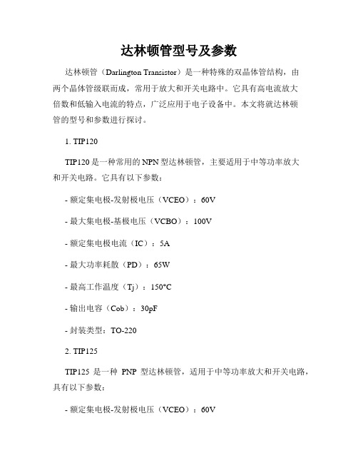
达林顿管型号及参数达林顿管(Darlington Transistor)是一种特殊的双晶体管结构,由两个晶体管级联而成,常用于放大和开关电路中。
它具有高电流放大倍数和低输入电流的特点,广泛应用于电子设备中。
本文将就达林顿管的型号和参数进行探讨。
1. TIP120TIP120是一种常用的NPN型达林顿管,主要适用于中等功率放大和开关电路。
它具有以下参数:- 额定集电极-发射极电压(VCEO):60V- 最大集电极-基极电压(VCBO):100V- 额定集电极电流(IC):5A- 最大功率耗散(PD):65W- 最高工作温度(Tj):150°C- 输出电容(Cob):30pF- 封装类型:TO-2202. TIP125TIP125是一种PNP型达林顿管,适用于中等功率放大和开关电路,具有以下参数:- 额定集电极-发射极电压(VCEO):60V- 最大集电极-基极电压(VCBO):60V- 额定集电极电流(IC):5A- 最大功率耗散(PD):65W- 最高工作温度(Tj):150°C- 输出电容(Cob):30pF- 封装类型:TO-2203. MPSA14MPSA14是一种通用型NPN型达林顿管,常用于低噪声放大和开关电路,具有以下参数:- 额定集电极-发射极电压(VCEO):30V- 最大集电极-基极电压(VCBO):40V- 额定集电极电流(IC):500mA- 最大功率耗散(PD):625mW- 最高工作温度(Tj):150°C- 输出电容(Cob):4.5pF- 封装类型:TO-924. MPSA13MPSA13是一种通用型PNP型达林顿管,适用于低噪声放大和开关电路,具有以下参数:- 额定集电极-发射极电压(VCEO):30V- 最大集电极-基极电压(VCBO):40V- 额定集电极电流(IC):500mA- 最大功率耗散(PD):625mW- 最高工作温度(Tj):150°C- 输出电容(Cob):4.5pF- 封装类型:TO-925. TIP122TIP122是一种高功率NPN型达林顿管,适用于高频放大和开关电路,常用于电机驱动等应用场合,具有以下参数:- 额定集电极-发射极电压(VCEO):100V- 最大集电极-基极电压(VCBO):100V- 额定集电极电流(IC):5A- 最大功率耗散(PD):65W- 最高工作温度(Tj):150°C- 输出电容(Cob):65pF- 封装类型:TO-220总结:以上介绍了几种常见的达林顿管型号及其参数,包括TIP120、TIP125、MPSA14、MPSA13和TIP122。
SUP57N20-33_08中文资料
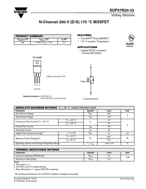
Vishay SiliconixSUP57N20-33N-Channel 200-V (D-S) 175 °C MOSFETFEATURES•TrenchFET ® Power MOSFET •175 °C Junction TemperatureAPPLICATIONS•Isolated DC/DC converters- Primary-Side SwitchPRODUCT SUMMARYV(BR)DSS (V)r DS(on) (Ω)I D (A)2000.033 at V GS = 10 V57Notes:a. Duty cycle ≤ 1 %.b. See SOA curve for voltage derating.c. When Mounted on 1" square PCB (FR-4 material).* Pb containing terminations are not RoHS compliant, exemptions may apply.ABSOLUTE MAXIMUM RATINGS T C = 25°C, unless otherwise notedParameterSymbol Limit Unit Drain-Source Voltage V DS 200VGate-Source VoltageV GS± 20Continuous Drain Current (T J = 175 °C)T C = 25 °C I D 57AT C = 125 °C33Pulsed Drain Current I DM 140Avalanche CurrentI AS35Single Pulse Avalanche Energy a L = 0.1 mH E AS 61mJ Maximum Power DissipationaT C = 25 °C P D 300b W T A = 25 °C c3.75Operating Junction and Storage T emperature RangeT J , T stg- 55 to 175°CTHERMAL RESISTANCE RATINGSParameterSymbol Limit Unit Junction-to-Ambient (PCB Mount)c R thJA 40°C/WJunction-to-Case (Drain)R thJC0.5Vishay SiliconixSUP57N20-33Notes:a. Pulse test; pulse width ≤ 300 µs, duty cycle ≤ 2 %.b. Guaranteed by design, not subject to production testing.c. Independent of operating temperature.Stresses beyond those listed under “Absolute Maximum Ratings” may cause permanent damage to the device. These are stress ratings only, and functional operation of the device at these or any other conditions beyond those indicated in the operational sections of the specifications is not implied. Exposure to absolute maximum rating conditions for extended periods may affect device reliability.SPECIFICATIONS T J = 25°C, unless otherwise notedParameter Symbol Test Conditions Min Typ Max UnitStaticDrain-Source Breakdown Voltage V (BR)DSS V DS = 0 V , I D = 250 µA 200V Gate-Threshold Voltage V GS(th) V DS = V GS , I D = 250 µA 24Gate-Body LeakageI GSS V DS = 0 V, V GS = ± 20 V ± 100nAZero Gate Voltage Drain Current I DSS V DS = 160 V , V GS = 0 V 1µA V DS = 160 V, V GS = 0 V , T J = 125 °C 50V DS = 160 V, V GS = 0 V , T J = 175 °C250On-State Drain Current aI D(on) V DS ≥ 5 V , V GS = 10 V 120A Drain-Source On-State Resistance a r DS(on) V GS = 10 V, I D = 30 A 0.0270.033ΩV GS = 10 V, I D = 30 A, T J = 125 °C 0.069V GS = 10 V, I D = 30 A, T J = 175 °C0.093Forward T ransconductance a g fsV DS = 15 V , I D = 30 A25S Dynamic bInput Capacitance C iss V GS = 0 V , V DS = 25 V , f = 1 MHz5100pFOutput CapacitanceC oss 480Reverse Transfer Capacitance C rss 210Total Gate Charge c Q g V DS = 100 V , V GS = 10 V , ID = 85 A 90130nC Gate-Source Charge c Q gs 23Gate-Drain Charge c Q gd 34Turn-On Delay Time c t d(on) V DD = 100 V, R L = 1.5 Ω I D ≅ 65 A, V GEN = 10 V , R G = 2.5 Ω2435nsRise Time ct r 220330Turn-Off Delay Time c t d(off) 4570Fall Time ct f200300Source-Drain Diode Ratings and Characteristics (T C = 25°C)b Continuous Current I S 65A Pulsed Current I SM 140Forward Voltage a V SD I F = 65 A, V GS = 0 V 1.0 1.5V Reverse Recovery Time t rr I F = 50 A, di/dt = 100 A/µs130200ns Peak Reverse Recovery Current I RM(REC)812A Reverse Recovery ChargeQ rr0.521.2µCOutput CharacteristicsTransfer CharacteristicsVishay SiliconixSUP57N20-33TYPICAL CHARACTERISTICS 25°C, unless otherwise notedAvalanche Current vs. TimeDrain Source Breakdown vs. Junction TemperatureVishay SiliconixSUP57N20-33THERMAL RATINGSVishay Silicon ix main tain s worldwide man ufacturin g capability. Products may be man ufactured at on e of several qualified location s. Reliability data for Silicon Technology and Package Reliability represent a composite of all qualified locations. For related documents such as package/tape drawin gs, part markin g, an d reliability data, see /ppg?72100.Maximum Avalanche and Drain Currentvs. Case TemperatureSafe Operating AreaNormalized Thermal Transient Impedance, Junction-to-CaseDisclaimer Legal Disclaimer NoticeVishayAll product specifications and data are subject to change without notice.Vishay Intertechnology, Inc., its affiliates, agents, and employees, and all persons acting on its or their behalf (collectively, “Vishay”), disclaim any and all liability for any errors, inaccuracies or incompleteness contained herein or in any other disclosure relating to any product.Vishay disclaims any and all liability arising out of the use or application of any product described herein or of any information provided herein to the maximum extent permitted by law. The product specifications do not expand or otherwise modify Vishay’s terms and conditions of purchase, including but not limited to the warranty expressed therein, which apply to these products.No license, express or implied, by estoppel or otherwise, to any intellectual property rights is granted by this document or by any conduct of Vishay.The products shown herein are not designed for use in medical, life-saving, or life-sustaining applications unless otherwise expressly indicated. Customers using or selling Vishay products not expressly indicated for use in such applications do so entirely at their own risk and agree to fully indemnify Vishay for any damages arising or resulting from such use or sale. Please contact authorized Vishay personnel to obtain written terms and conditions regarding products designed for such applications.Product names and markings noted herein may be trademarks of their respective owners.元器件交易网。
FQD20N06中文资料

100
80 V = 10V
GS
60
VGS = 20V
40
20
※ Note : T = 25℃ J
0
0
10
20
30
40
50
ID, Drain Current [A]
Figure 3. On-Resistance Variation vs. Drain Current and Gate Voltage
1200
--
5
20
ns
--
45 100
ns
-- 20
50
ns
(Note 4, 5)
--
25
60
ns
VDS = 48 V, ID = 20 A,
-- 11.5 15
nC
VGS = 10 V
--
3
--
nC
(Note 4, 5)
--
4.5
--
nC
Drain-Source Diode Characteristics and Maximum Ratings
FQD20N06 / FQU20N06
元器件交易网
Electrical Characteristics
Symbol
ParameterFra bibliotekTC = 25°C unless otherwise noted
Test Conditions
Min Typ Max Units
Off Characteristics
- Derate above 25°C
Operating and Storage Temperature Range
Maximum lead temperature for soldering purposes, 1/8" from case for 5 seconds
喷射器与静态混合器介绍
Change life with heart
5
Part1 :喷射器( Injector )的概述
喷射器恐怕是再生槽的最关健部件,只要它运行不理想,再生系统就要出问题,从而使 整个脱硫系统形成恶性循环。喷射器部件不大,但关健部位甚多。设计计算主要有这么 几项:一是喷嘴计算;二是混合管计算;三是吸气室计算;四是尾管直径计算;五是扩 散管长度计算。
Change life with heart
3
Part1 :喷射器( Injector )的概述
喷射器的优点:具有设计合理、结构紧凑、操作方便、药液混合效果良好、使用寿命 长等。 喷射器的应用:喷射器是热电、炼油、医药、环保等水处理系统中输送、稀释药液的 小设备。 喷射器的注意事项: 1,安装后必须进行水压实验,保证安装质量,水压实验为高压原水的工作压力,且不大于 0.588MPa(兆帕),即6KGf/cm2. 2,喷射器在使用时不需特别的维护,但应避免日光直接长期照射,雨淋及锐物撞击,损伤. 3,外部联结管道内径均不小于喷射器相应接管的公称直径,法兰垫片内径应大于法兰 内孔直径.
喷射器与静态混合器
审 批
职位/姓名 日 期 保存年限 作 成 确 认 审 核1 审 核2 批准
Written By: Date:
/ /
** 2010/3/8
/ /
0, 1, 3, 5, 永久
FQP10N20C中文资料
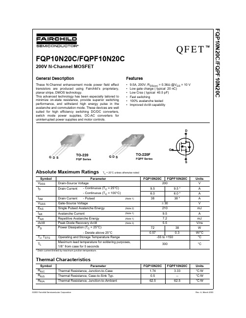
VGS = 0 V, ID = 250 µA
200 --
ID = 250 µA, Referenced to 25°C -- 0.28
IDSS
Zero Gate Voltage Drain Current
VDS = 200 V, VGS = 0 V VDS = 160 V, TC = 125°C
--
VGS = 0 V, IS = 9.5 A,
-- 158
--
ns
Qrr
Reverse Recovery Charge
dIF / dt = 100 A/µs
(Note 4) -- 0.97
--
µC
Notes:
1. Repetitive Rating : Pulse width limited by maximum junction temperature 2. L = 3.5mH, IAS = 9.5A, VDD = 50V, RG = 25 Ω, Starting TJ = 25°C 3. ISD ≤ 9.5A, di/dt ≤ 300A/µs, VDD ≤ BVDSS, Starting TJ = 25°C 4. Pulse Test : Pulse width ≤ 300µs, Duty cycle ≤ 2% 5. Essentially independent of operating temperature
VGS(th) RDS(on)
Gate Threshold Voltage
Static Drain-Source On-Resistance
gFS
Forward Transconductance
VDS = VGS, ID = 250 µA
FQB44N10中文资料
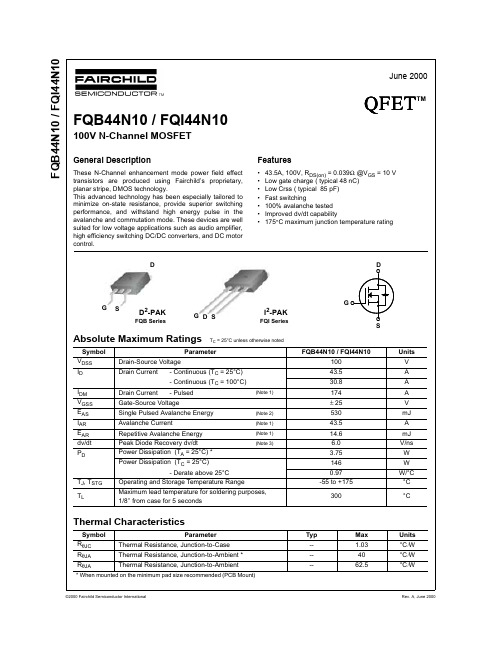
Turn-On Delay Time
tr
Turn-On Rise Time
td(off)
Turn-Off Delay Time
tf
Turn-Off Fall Time
Qg
Total Gate Charge
Qgs
Gate-Source Charge
Qgd
Gate-Drain Charge
VDD = 50 V, ID = 43.5 A, RG = 25 Ω
10-1 0.2 0.4
25℃
※ Notes : 1. VGS = 0V 2. 250μs Pulse Test
0.6 0.8 1.0 1.2 1.4 1.6 1.8 2.0 V , Source-Drain Voltage [V]
-55 to +175
300
Units V A A A V mJ A mJ
V/ns W W
W/°C °C
°C
Thermal Characteristics
Symbol
Parameter
RθJC
Thermal Resistance, Junction-to-Case
RθJA
Thermal Resistance, Junction-to-Ambient *
4000 3500 3000 2500 2000 1500 1000 500
0 10-1
Ciss = Cgs + Cgd (Cds = shorted) Coss = Cds + Cgd Crss = Cgd
Ciss C
oss
C rss
※ Notes :
1. VGS = 0 V 2. f = 1 MHz
变频谐振试验装置210-105说明书
DWXB-210kVA/105kV变频串联谐振耐压试验装置使用说明书武汉德威电力测试设备有限公司尊敬的顾客感谢您购买本公司变频谐振试验装臵。
在您初次使用该产品前,请您详细地阅读本使用说明书,将可能帮助您熟练地使用本仪器。
我们的宗旨是不断地改进和完善公司的产品,因此您所使用的产品可能与使用说明书有少许的差别。
如果有改动的话,我们会用附页方式告知,敬请谅解!您有不清楚之处,请与公司售后服务部联络,我们定会满足您的要求。
慎重保证本公司生产的产品,在发货之日起三个月内,如产品出现缺陷,实行包换。
一年(包括一年)内如产品出现缺陷,实行免费维修。
一年以上如产品出现缺陷,实行有偿终身维修。
安全要求请阅读下列安全注意事项,以免人身伤害,并防止本产品或与其相连接的任何其它产品受到损坏。
为了避免可能发生的危险,本产品只可在规定的范围内使用。
只有合格的技术人员才可执行维修—防止火灾或人身伤害!使用适当的电源线:只可使用本产品专用、并且符合本产品规格的电源线。
正确地连接和断开:当测试导线与带电端子连接时,请勿随意连接或断开测试导线。
产品接地:本产品除通过电源线接地导线接地外,产品外壳的接地柱必须接地。
为了防止电击,接地导体必须与地面相连。
在与本产品输入或输出终端连接前,应确保本产品已正确接地。
注意所有终端的额定值:为了防止火灾或电击危险,请注意本产品的所有额定值和标记。
在对本产品进行连接之前,请阅读本产品使用说明书,以便进一步了解有关额定值的信息。
请勿在无仪器盖板时操作:如盖板或面板已卸下,请勿操作本产品。
在有可疑的故障时,请勿操作:如怀疑本产品有损坏,请本公司维修人员进行检查,切勿继续操作。
请勿在潮湿环境下操作请勿在易暴环境中操作保持产品表面清洁和干燥变频串联谐振试验装臵操作手册目录:第一章产品概述第二章DWXB-210kVA/105kV变频串联谐振耐压试验装臵主要技术参数第三章DWXB-210kVA/105kV变频串联谐振耐压试验装臵设备应用第四章变频电源详细使用介绍第五章变频电源通用说明第六章常见故障排除第七章相关资料第一章产品概述该装臵主要针10kV电缆,135MW/13.8kV火力发电机及以下35kV电力主变压器、母线开关等所有电气主设备的交流耐压试验设计制造。
IXFN120N20中文资料
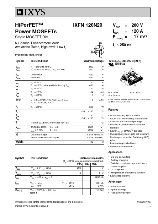
Symbol Test ConditionsMaximum RatingsV DSS T J = 25°C to 150°C200V V DGR T J = 25°C to 150°C; R GS = 1 M W 200V V GS Continuous ±20V V GSM Transient±30V I D25T C = 25°C120A I DM T C = 25°C, pulse width limited by T JM 480A I AR T C = 25°C 120A E AR T C = 25°C 64mJ E AS T C = 25°C3J dv/dt I S £ I DM , di/dt £ 100 A/m s, V DD £ V DSS 5V/ns T J £ 150°C, R G = 2 W P D T C = 25°C600W T J -55 ... +150°C T JM 150°C T stg -55 ... +150°C T L 1.6 mm (0.063 in.) from case for 10 s -°C V ISOL 50/60 Hz, RMS t = 1 min 2500V~I ISOL £ 1 mAt = 1 s3000V~M d Mounting torque1.5/13 Nm/lb.in.Terminal connection torque 1.5/13Nm/lb.in.Weight30gSymbol Test ConditionsCharacteristic Values(T J = 25°C, unless otherwise specified)min.typ.max.V DSS V GS = 0 V, I D = 3mA 200V V GS(th) V DS = V GS , I D = 8mA 24 V I GSS V GS = ±20 V, V DS = 0±200 nAI DSS V DS = V DSS T J = 25°C 100 m A V GS = 0 VT J = 125°C2 mA R DS(on)V GS = 10 V, I D = 0.5 • I D2517 m WNote 196538C (7/99)IXFN 120N20V DSS = 200V I D25= 120A R DS(on)=17 m Wt rr £ 250 nsHiPerFET TMPower MOSFETsSingle MOSFET DieN-Channel Enhancement ModeAvalanche Rated, High dv/dt, Low t rrSGSDminiBLOC, SOT-227 B (IXFN) E153432G = Gate D = DrainS = SourceEither Source terminal at miniBLOC can be used as Main or Kelvin SourceFeatures•Encapsulating epoxy meetsUL 94 V-0, flammability classification •International standard package •miniBLOC, with Aluminium nitride isolation•Low R DS (on) HDMOS TM process•Rugged polysilicon gate cell structure •Unclamped Inductive Switching (UIS)rated•Low package inductance •Fast intrinsic Rectifier Applications•DC-DC converters •Battery chargers•Switched-mode and resonant-modepower supplies •DC choppers•Temperature and lighting controls •Low voltage relays Advantages•Easy to mount •Space savings •High power densityPreliminary data sheetIXYS reserves the right to change limits, test conditions, and dimensions.Symbol Test Conditions Characteristic Values Array= 25°C, unless otherwise specified)(T ArrayNote: 1. Pulse test, t £ 300 m s, duty cycle d £ 2 %。
10KV降压变电所_
I
华北科技学院毕业设计(论文)
Abstract
Although electric energy is the major energy and power of the industrial production in the factory, it takes a very small proportion in the production costs, whereas the electrochemical industry is excluded. The importance of electric energy in the industrial production is not how much the proportion it takes in the production costs or the total investment, instead, the reason for its importance is that it can bring lots of benefits and advantages after the industrial production realizes electrification, such as more production, higher product quality and labor productivity and less production costs, what’s more, it is also beneficial to reduce labor intensity and improve the working conditions so as to achieve the production process automation. However, on the other hand, it may result in serious consequences in the industrial production in case that the power supply of the factory is suddenly broken/ cut off. For this reason, it is of great importance and significance to do this design.
BSN20 PDF规格书
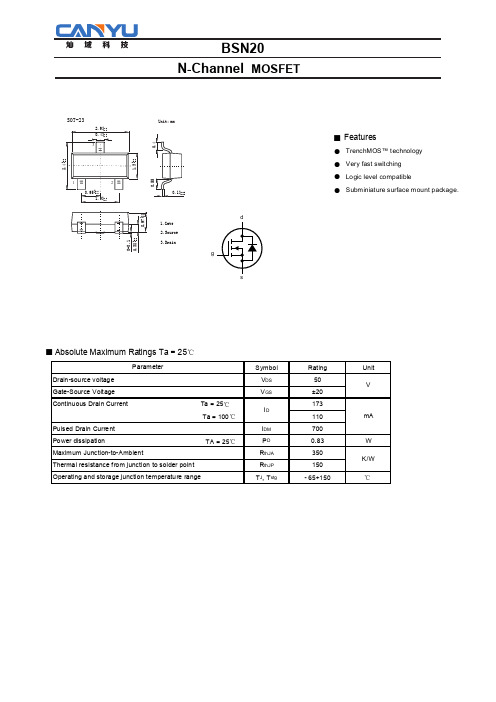
Features TrenchMOS™ technology Very fast switchingLogic level compatibleSubminiature surface mount package. Absolute Maximum Ratings Ta = 25℃gBSN201.Gate2.Source3.DrainUnit:mmSOT-23■ Fe● ● ● ●■N-Channel MOSFETElectrical Characteristics Ta = 25℃Marking■ FeBSN20N-Channel MOSFETTypical CharacteristicsV GS ≥5VFig 1.Normalized total power dissipation as afunction of solder point temperature.Fig 2.Normalized continuous drain current as afunction of solder point temperature.T sp =25°C; I DM is single pulse.Fig 3.Safe operating area; continuous and peak drain currents as a function of drain-source voltage.020406080100120255075100125150175P derT sp (o C)(%)204060801001200255075100125150175I der (%)T sp (o C)P derP totPtot 25C°----------------------100%×=I der I D ID 25C°------------------100%×=10101010112V DS (V)I D (A)Mounted on a metal clad substrate.Fig 4.Transient thermal impedance from junction to solder point as a function ofpulse duration.Z ( )( )BSN20N-Channel MOSFETT j =25°T C j =25°C and 150°C; V DS ≥I D ×R DSonFig 5.Output characteristics: drain current as afunction of drain-source voltage;typical values.Fig 6.Transfer characteristics: drain current as afunction of gate-source voltage; typical values.T j =25°CFig 7.Drain-source on-state resistance as a functionof drain current; typical values.Fig 8.Normalized drain-source on-state resistancefactor as a function of junction temperature.I D(A)00.10.20.30.40.50.60.70.8012345678910V GS (V)I D(A)0123456789100.10.20.30.40.50.60.7I D (A)R DSon(Ω)00.20.40.60.811.21.41.61.822.2-60-202060100140180T j(o C)a a R DSonR DSon 25C°---------------------------=I D =1mA; V DS =V GS T j =25°C; V DS =5VFig 9.Gate-source threshold voltage as a function ofjunction temperature.Fig 10.Sub-threshold drain current as a function ofgate-source voltage.00.20.40.60.811.21.41.61.82-60-202060100140180T j (o C)V GS(th)(V)00.20.40.60.811.2 1.4 1.6 1.82V GS (V)I D (A)101010101010■ Typical Characterisitics( )BSN20N-Channel MOSFETT j =25°C and 150°C; V DS ≥I D ×R DSon V GS =0V; f =1MHzFig 11.Forward transconductance as a function ofdrain current; typical values.Fig 12.Input,output and reverse transfer capacitancesas a function of drain-source voltage; typical values.g fs(S)11010210-1110102V DS (V)C iss , C ossC rss (pF)T j =25°C and 150°C; V GS =0VFig 13.Source (diode forward) current as a function of source-drain (diode forward)voltage; typical values.I S(A)■ Typical CharacterisiticsBSN20N-Channel MOSFET。
三极管大全

BUT11A NPN 28 开关 功放 1000V5A100W
BUT12A NPN 28 开关 功放 450V10A125W
BUV26 NPN 28 音频功放开关 90V14A65W /250ns
BUV28A NPN 28 音频功放开关 225V10A65W /250ns
MJ11033 PNP 12 电源开关 120V50A300W DAR-L
MJ13333 NPN 12 电源开关 400V20A175W
MJ15024 NPN 12 音频功放开关 400V16A250W4MHZ(原25.00)
MJ15025 PNP 12 音频功放开关 400V16A250W4MHZ(原25.00)
MJ10012 NPN 12 达林顿 400V10A175W
MJ10015 NPN 12 电源开关 400V50A200W
MJ10016 NPN 12 电源开关 500V50A200W
MJ10025 12 电源开关 850V20A250W
MJ11032 NPN 12 电源开关 120V50A300W DAR-L
BU2527AF NPN 30 开关 功放 1500V15A150W
BU2532AW NPN 30 开关 功放 1500V15A150W(大屏)
BUH515 NPN BCE 行管 1500V10A80W
BUH515D NPN BCE 行管 1500V10A80W(带阻尼)
BUS13A NPN 12 开关 功放 1000V15A175W
BUV48A NPN 30 音频功放开关 450V15A150W
BUW13A NPN 30 功放开关 1000V15A150W
FDP61N20中文资料
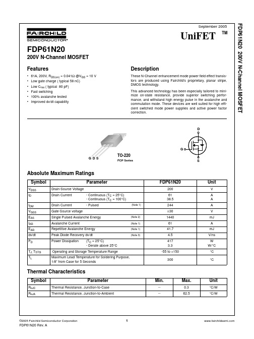
FDP61N20
200V N-Channel MOSFET
Features
• 61A, 200V, RDS(on) = 0.041Ω @VGS = 10 V • Low gate charge ( typical 58 nC) • Low Crss ( typical 80 pF) • Fast switching • 100% avalanche tested • Improved dv/dt capability
VDD = 100V, ID = 61A RG = 25Ω
VDS = 160V, ID = 61A VGS = 10V
Drain-Source Diode Characteristics and Maximum Ratings
--
--
--
(Note 4, 5)
--
--
--
(Note 4, 5)
--
IS
FDP61N20 Rev. A
2
FDP61N20 200V N-Channel MOSFET
Typical Performance Characteristics
Figure 1. On-Region Characteristics
V GS
Top : 15.0 V
VDS = 40V, ID =30.5A
(Note 4) --
Ciss
Input Capacitance
VDS = 25V, VGS = 0V,
--
Coss
Output Capacitance
f = 1.0MHz
--
Crss
Reverse Transfer Capacitance
LZZBW-10电流互感器
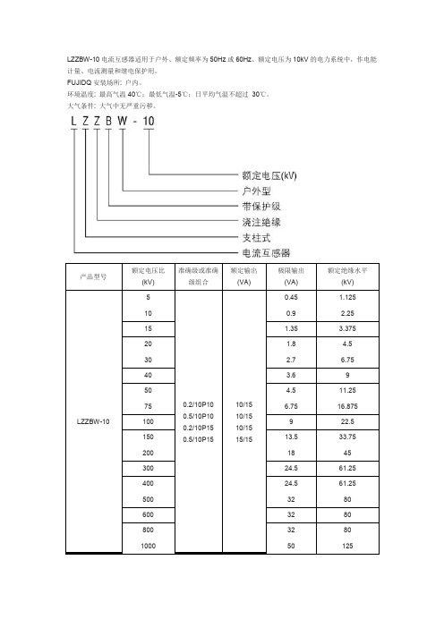
准确级或准确 级组合Fra bibliotek额定输出 (VA)
极限输出 (VA) 0.45 0.9 1.35 1.8 2.7 3.6 4.5
额定绝缘水平 (kV) 1.125 2.25 3.375 4.5 6.75 9 11.25 16.875 22.5 33.75 45 61.25 61.25 80 80 80 125
0.2/10P10 0.5/10P10 0.2/10P15 0.5/10P15
10/15 10/15 10/15 15/15
6.75 9 13.5 18 24.5 24.5 32 32 32 50
LZZBW-10
100 150 200 300 400 500 600 800 1000
本型电流互感器为户外型、 环氧树脂浇注全封闭结构, 具有优良的绝缘性能和防潮能力。 该产品结构紧凑、 体积小、重量轻且容易表面清洁。二次接线处装有接线盒,产品底板上有接地螺栓及供安装用的四个安装 孔。
LZZBW-10 电流互感器适用于户外、额定频率为 50Hz 或 60Hz、额定电压为 10kV 的电力系统中,作电能 计量、电流测量和继电保护用。 FUJIDQ 安装场所: 户内。 环境温度: 最高气温 40℃;最低气温-5℃;日平均气温不超过 30℃。 大气条件: 大气中无严重污秽。
产品型号
额定电压比 (kV) 5 10 15 20 30 40 50 75
东元变频器N310的概述
N310特点:特点:高性能矢量控制,低频特性好,精度高且可靠,可实现闭回路控制,功率范围更宽频率范围:N310 0.01~400.00Hz N312 0.1~1200.0Hz 功率范围:220V机种0.4~2.2KW扩展卡:I/O扩展:3in/3out扩展卡N31IO-01 PG卡:NL-5V、PVTL-5V、N-12V、PVT-12V380V机种0.75~55KWN310产品特色:Ø高性能设计采用32 bits CPU,高速处理与内部庞大记忆体提升向量控制性能内建V/F、向量控制已增电流向量/Close loop控制提升低速转矩与速度运转稳定度控制高速响应控制高容量记忆体,提供大量之程式与参数容量提供客制化设计之基础强化保护功能透过高速运算,提升失速防止功能,让机台不易跳机Ø高性能设计内建更强大应用功能16段速+ Sequence control + 16段Acc/Dec时间调整nRS485通信功能标准内建ModbusProfibus-DP,DeviceNet ,TCP/IP通信卡扩充nPID功能多机能DI/O、AI/O功能艾驰商城是国内最专业的MRO工业品网购平台,正品现货、优势价格、迅捷配送,是一站式采购的工业品商城!具有10年工业用品电子商务领域研究,以强大的信息通道建设的优势,以及依托线下贸易交易市场在工业用品行业上游供应链的整合能力,为广大的用户提供了传感器、图尔克传感器、变频器、断路器、继电器、PLC、工控机、仪器仪表、气缸、五金工具、伺服电机、劳保用品等一系列自动化的工控产品。
如需进一步了解相关变频器产品的选型,报价,采购,参数,图片,批发等信息,请关注艾驰商城。
/。
NPN小信号达林顿晶体管说明书

© Semiconductor Components Industries, LLC, 2010 September, 2010 − Rev. 61Publication Order Number:BSP52T1/DBSP52T1G, BSP52T3GNPN Small-SignalDarlington TransistorThis NPN small signal Darlington transistor is designed for use in switching applications, such as print hammer, relay, solenoid and lamp drivers. The device is housed in the SOT-223 package, which is designed for medium power surface mount applications.Features•The SOT-223 Package can be soldered using wave or reflow. The formed leads absorb thermal stress during soldering, eliminating the possibility of damage to the die•Available in 12 mm Tape and ReelUse BSP52T1 to Order the 7 Inch/1000 Unit Reel•PNP Complement is BSP62T1•These Devices are Pb−Free, Halogen Free/BFR Free and are RoHS CompliantMAXIMUM RATINGS (T C = 25°C unless otherwise noted)Rating Symbol Max Unit Collector-Emitter Voltage V CES80Vdc Collector-Base Voltage V CBO90Vdc Emitter-Base Voltage V EBO 5.0Vdc Collector Current I C 1.0AdcTotal Power Dissipation (Note 1) @ T A = 25°CDerate above 25°C P D0.86.4WmW/°CTotal Power Dissipation (Note 2) @ T A = 25°CDerate above 25°C P D1.2510WmW/°COperating and StorageTemperature RangeT J, T stg−65 to 150°C THERMAL CHARACTERISTICSCharacteristic Symbol Value Unit Thermal Resistance (Note 1)Junction-to-AmbientR q JA156°C/WThermal Resistance (Note 2) Junction-to-Ambient R qJA100°C/WMaximum Temperature for SolderingPurposesTime in Solder Bath T L26010°CSecStresses exceeding Maximum Ratings may damage the device. Maximum Ratings are stress ratings only. Functional operation above the Recommended Operating Conditions is not implied. Extended exposure to stresses above the Recommended Operating Conditions may affect device reliability.1.Device mounted on a FR-4 glass epoxy printed circuit board using minimumrecommended footprint.2.Device mounted on a FR-4 glass epoxy printed circuit board using 1 cm2 pad.Device Package Shipping†ORDERING INFORMATIONMARKING DIAGRAMSOT−223CASE 318ESTYLE 11AYWAS3GGA= Assembly LocationY= YearW= Work WeekAS3= Specific Device CodeG= Pb−Free Package(Note: Microdot may be in either location)MEDIUM POWERNPN SILICONSURFACE MOUNT DARLINGTON TRANSISTORBSP52T1G SOT−223(Pb−Free)1000/Tape & Reel†For information on tape and reel specifications, including part orientation and tape sizes, please refer to our T ape and Reel Packaging Specifications Brochure, BRD8011/D.BSP52T3G SOT−223(Pb−Free)4000/Tape & ReelELECTRICAL CHARACTERISTICS (T A = 25°C unless otherwise noted)Characteristics Symbol Min Max Unit OFF CHARACTERISTICSCollector-Base Breakdown Voltage (I C = 100 m Adc, I E = 0)V(BR)CBO90−VdcEmitter-Base Breakdown Voltage (I E = 10 m Adc, I C = 0)V(BR)EBO5.0−VdcCollector-Emitter Cutoff Current (V CE = 80 Vdc, V BE = 0)I CES−10m AdcEmitter-Base Cutoff Current (V EB = 4.0 Vdc, I C = 0)I EBO−10m AdcON CHARACTERISTICS (Note 3)DC Current Gain(I C = 150 mAdc, V CE = 10 Vdc) (I C = 500 mAdc, V CE = 10 Vdc)h FE10002000−−−Collector-Emitter Saturation Voltage (I C = 500 mAdc, I B = 0.5 mAdc)V CE(sat)− 1.3VdcBase-Emitter Saturation Voltage (I C = 500 mAdc, I B = 0.5 mAdc)V BE(sat)− 1.9Vdc3.Pulse Test: Pulse Width ≤ 300 m s, Duty Cycle ≤ 2.0%2PACKAGE DIMENSIONSSOT −223 (TO −261)CASE 318E −04ISSUE NSTYLE 1:PIN 1.BASE2.COLLECTOR3.EMITTER4.COLLECTORNOTES: 1.DIMENSIONING AND TOLERANCING PER ASME Y14.5M,1994. 2.CONTROLLING DIMENSION: INCH.SOLDERING FOOTPRINT*DIM A MIN NOM MAX MIN MILLIMETERS 1.50 1.63 1.750.060INCHESA10.020.060.100.001b 0.600.750.890.024b1 2.90 3.06 3.200.115c 0.240.290.350.009D 6.30 6.50 6.700.249E 3.30 3.50 3.700.130e 2.20 2.30 2.400.0870.850.94 1.050.0330.0640.0680.0020.0040.0300.0350.1210.1260.0120.0140.2560.2630.1380.1450.0910.0940.0370.041NOM MAX L1 1.50 1.75 2.000.0606.707.007.300.2640.0690.0780.2760.287H E −−e10°10°0°10°q L 0.20−−−−−−0.008−−−−−−*For additional information on our Pb −Free strategy and solderingdetails, please download the ON Semiconductor Soldering and Mounting Techniques Reference Manual, SOLDERRM/D.ON Semiconductor and are registered trademarks of Semiconductor Components Industries, LLC (SCILLC). SCILLC reserves the right to make changes without further notice to any products herein. SCILLC makes no warranty, representation or guarantee regarding the suitability of its products for any particular purpose, nor does SCILLC assume any liability arising out of the application or use of any product or circuit, and specifically disclaims any and all liability, including without limitation special, consequential or incidental damages.“Typical” parameters which may be provided in SCILLC data sheets and/or specifications can and do vary in different applications and actual performance may vary over time. All operating parameters, including “Typicals” must be validated for each customer application by customer’s technical experts. SCILLC does not convey any license under its patent rights nor the rights of others. SCILLC products are not designed, intended, or authorized for use as components in systems intended for surgical implant into the body, or other applications intended to support or sustain life, or for any other application in which the failure of the SCILLC product could create a situation where personal injury or death may occur.Should Buyer purchase or use SCILLC products for any such unintended or unauthorized application, Buyer shall indemnify and hold SCILLC and its officers, employees, subsidiaries,affiliates, and distributors harmless against all claims, costs, damages, and expenses, and reasonable attorney fees arising out of, directly or indirectly, any claim of personal injury or death associated with such unintended or unauthorized use, even if such claim alleges that SCILLC was negligent regarding the design or manufacture of the part. SCILLC is an Equal Opportunity/Affirmative Action Employer. This literature is subject to all applicable copyright laws and is not for resale in any manner.PUBLICATION ORDERING INFORMATION。
HGTP10N120BN中文资料

TC = 25oC, Unless Otherwise Specified HGTG10N120BN HGTP10N120BN HGT1S10N120BNS Collector to Emitter Voltage . . . . . . . . . . . . . . . . . . . . . . . . . . . . . . . . . . . . . . . . . . . . . .BVCES Collector Current Continuous At TC = 25oC . . . . . . . . . . . . . . . . . . . . . . . . . . . . . . . . . . . . . . . . . . . . . . . . . . . . . . . . . IC25 At TC = 110oC . . . . . . . . . . . . . . . . . . . . . . . . . . . . . . . . . . . . . . . . . . . . . . . . . . . . . . . IC110 Collector Current Pulsed (Note 1) . . . . . . . . . . . . . . . . . . . . . . . . . . . . . . . . . . . . . . . . . . . ICM Gate to Emitter Voltage Continuous. . . . . . . . . . . . . . . . . . . . . . . . . . . . . . . . . . . . . . . . . VGES Gate to Emitter Voltage Pulsed . . . . . . . . . . . . . . . . . . . . . . . . . . . . . . . . . . . . . . . . . . . .VGEM Switching Safe Operating Area at TJ = 150oC (Figure 2) . . . . . . . . . . . . . . . . . . . . . . . SSOA Power Dissipation Total at TC = 25oC . . . . . . . . . . . . . . . . . . . . . . . . . . . . . . . . . . . . . . . . . PD Power Dissipation Derating TC > 25oC . . . . . . . . . . . . . . . . . . . . . . . . . . . . . . . . . . . . . . . . . . Forward Voltage Avalanche Energy (Note 2) . . . . . . . . . . . . . . . . . . . . . . . . . . . . . . . . . . . EAV Operating and Storage Junction Temperature Range . . . . . . . . . . . . . . . . . . . . . . . . TJ, TSTG Maximum Temperature for Soldering Leads at 0.063in (1.6mm) from Case for 10s. . . . . . . . . . . . . . . . . . . . . . . . . . . . . . . . . . TL Package Body for 10s, see Tech Brief 334. . . . . . . . . . . . . . . . . . . . . . . . . . . . . . . . . . .Tpkg Short Circuit Withstand Time (Note 3) at VGE = 15V. . . . . . . . . . . . . . . . . . . . . . . . . . . . . .tSC Short Circuit Withstand Time (Note 3) at VGE = 12V. . . . . . . . . . . . . . . . . . . . . . . . . . . . . .tSC 35 17 80 ±20 ±30 55A at 1200V 298 2.38 80 -55 to 150 300 260 8 15 W W/oC mJ
18_3护栏钢筋构造(三)

