附二JACKTON电动搬运车图册
电动托盘搬运车参数 图片
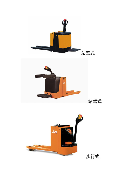
站驾式
站驾式
步行式
电动托盘搬运车简介
电动托盘搬运叉车适合于狭窄通道和有限空间内的作业,是仓库、超市、车间内装卸和搬运托盘化货物的理想工具。
外形
●采用圆弧、,曲面造型,整车小巧美观。
稳定性
●五支点低重心设计,整车具有良好的稳定性。
机动性
●驱动单元采用中位布置、弹簧支承、可左右旋转近90度,转向灵活轻便,即使在凹凸路面亦能行走自如。
舒适性
●根据人机工程设计的操纵手柄集加速、换向、嗽叭、制动、起升/下降、紧急反向等功能,为操作最大程度的舒适性,设置高效阻尼减振器,将由于路面不平引起的振动减最小。
可靠性
●电机控制器、起升电机、液压泵等主要部件均选用国际一流产品。
●采用国际一流品牌LED电量显示表,能在强振动环境和很宽的温度范围内精确工作。
先进性
●高频MOSFET集成控制器和SEM驱动电机组成的先进的SEM行走控制系统,调速性能优异,具有再生制动、反接制动等功能,使操作更加安全舒适、经济高效。
●采用组合式液压动力单元,体积紧凑、噪音低、压力损失小。
●非线性变速功能在加速开关在较大行程时,驱动电机仅以较小的转速运转,因而叉车起步更加平衡,便于在窄小的空间操作。
安全性
●智能延时制动功能在停止前进和后退操作时,自动动作电磁制动器制动叉车,使操作更加安全。
紧急断电开关作为标准配置,符合欧洲安全标准。
电动托盘搬运车技术参数表。
电动托盘车(搬运车)培训教材ppt课件

拧紧螺栓,保证连 接可靠
;.
15
蓄电池的充电与保养
每辆车都配有一台充电器。打开充电器其中有两端接线处,其中一端连接 在蓄电池上(如左图所示),另一端连接在220V单向交流电的插座上(如
右图所示)。
;.
16
蓄电池的充电与保养
电动叉车普通充电时 间为6至8小时,如需 确定搬运车是否充满
;.
11
车辆使用方法及注意事项
为保证驾驶者的安全,该车 手柄上顶端设计了“急返开 关”,车辆前进时,若“急返 开关”受到挤压,则车辆立即
开始向反方向倒退
急返开关
;.
12
车辆使用方法及注意事项
前进:红色旋钮向内旋转 后退:红色旋钮向外旋转
上升
喇叭
下降
;.
13
蓄电池的充电与保养
02
;.
14
蓄电池的充电与保养
4 检查蓄电池是否有电
;.
7
车辆使用方法及注意事项
5 检查各支撑轮有无阻死现象,并保证车轮·不接触液体,以免脱胶
;.
8
车辆使用方法及注意事项
车辆前进时站立端在 前,货叉在后
前进
;.
9
车辆使用方法及注意事项
车辆倒车时货叉在前, 站立端在后
倒车
;.
10
车辆使用方法及注意事项
车辆制动时手柄为 0°或90°
;.
18
安全操作事项
03
;.
19
安全操作事项
禁止车辆在空载行驶 中,货叉位置站人
;.
20
安全操作事项
禁止坐在护栏上操作 车辆行驶
;.
21
杰克顿大型吊车型号2320.xx说明书
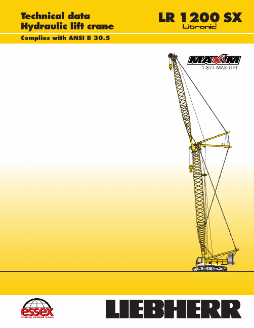
T echnical dataHydraulic lift craneComplies with ANSI B30.5LR1200SXDimensionsOperating weightThe operating weight includes the basic machine with crawlers, 2 main winches 26,500 l b s i ncludin g w ir e r ope s (853 ft a n d 1624 f t) a n d 66 f t m ain boom, consisting of A–frame, boom foot (33 ft), boom head (23 ft), boom extension (10 ft), 178,600 lbs basic counterweight, 79,400 lbs carbody counterweight a n d 551,100 l b s h oo k b lock.T ota l w eigh t a pprox. 463,000 l bsGround pressureGround b earin g p ressur e 16.5 P SI Basic machine with undercarriage EquipmentMain b oo m (No. 2320.xx) m ax. l engt h 282 f t Hig h r eac h (No. 2320.x x a n d 1916.xx) 384 f t Luffin g j i b (No. 1916.xx) m ax. l engt h 312 f t Max. c ombinatio n b oo m 174 ft a n d l uffin g j i b 312 f t Fixe d j i b (No. 1008.xx) 36 f t – 85 f t Auxiliar y j i b 53,000 l b s l iftin g c apacit y (optiona l 79,100 l bs)Remarks1.Th e l iftin g c apacitie s s tate d a r e v ali d f o r l iftin g o peratio n o nl y (corres–ponds w it h c ran e c lassificatio n a ccordin g t o F.E.M. 1.001, c ran e g rou p A1)2.Crane s tandin g o n f irm, h orizonta l g round.3.The w eigh t o f t h e l iftin g d evic e (hoistin g r opes, h oo k b lock, s hackl e e tc.)must b e d educte d f ro m t h e g ros s l iftin g c apacit y t o o btai n a n e t l iftin g value.4.Additional e quipmen t o n b oo m (e.g. b oo m w alkways, a uxiliar y j ib) m us tb e d educte d t o g e t t h e n e t l iftin gc apacity.5.For m ax. w in d s pee d p leas e r efe r t o l if t c har t i n o perator’s c a b o r m anual.6.Working r adi i a r e m easure d f ro m c entr e o f s win g a n d u nde r l oad.7.Th e l iftin g c apacitie s a r e v ali d f or 360 d egree s o f s wing.8.Calculatio n o f s tabilit y u nde r l oa d i s b ase d o n 75% t ippin g l oad,ANS I B 30.5 a n d I S O 4305 T abl e 2.9.Th e s tructure s a r e c alculate d a ccordin g t o F.E.M. 1.001 – 1998(E N 13001–2 / 2004).*)Including p endant straps , n umbers i n b rackets includ e a lso th e luffin g j i b p endant stapsBoom transport optionLength40’2” 20’6” 10’8”W eight in lbs*7,9604,3503,240No. 2320.xx/1916.xxx 40’ /40’ 20’ / 20’ 10’ /10’*) Including p endant strapsTransport dimensions and weightsLuffing jib(No. 1916.xx)Fixed jib head(No. 1008.20)Weight in lbs*2,060Width45”Fixed jib section(No. 1008.17)10ftWeight in lbs*660Width43.3”Fixed jib section(No. 1008.17)20ftWeight in lbs*1,010Width43.3”Fixed jib foot with A-frame(No. 1008.20)Weight in lbs*4,300Width59”Fixed jib(No. 1008.xx)Luffing jib head(No. 1916.21)Weight in lbs*3,400Width6’9”Luffing jib section(No. 1916.18)20ftWeight in lbs*1,520Width6’9”Luffing jib section(No. 1916.18)40ftWeight in lbs*2,760Width6’9”Luffing jib foot with A-frames(No. 1916.22)Weight in lbs*14,110Width6’9”Luffing jib section(No. 1916.18)10ftWeight in lbs*1,210Width6’9”L -boomsection tapered (No. 2320/1916.20)40ftWeight in lbs*5,810Width7’11”L -boom jib section(No. 1916.22)3ftWeight in lbs*1,000Width6’9”Transport dimensions and weightsCounterweightsCounterweight1xWeight in lbs31,970Width5’5”Counterweight1xW eight in lbs35,940Width5’5”Carbody counterweight2xWeight in lbs21,600Width11’HooksCounterweight10xW eight in lbs11,250Width54”551,200lbs hook block -11sheavesWeight in lbs5,070 7,050Width41” 49”353,000lbs hook block -7sheavesWeight in lbs3,3004,960 6,610Width25” 30” 35”27,600lbs single hookWeight in lbs1,300Width16”88,200lbs hook block -1sheaveWeight in lbs1,5002,450 3,300Width12” 16” 20”Carbody counterweight2xWeight in lbs18,300Width6’9”220,500lbs hook block -5sheavesWeight in lbs2,9004,000 5,070Width21” 25”30”Powe r r atin g a ccordin g to I S O 9249, 362 hp a t 2000 r p mEngin e t yp e L iebher r D 936 L A6Fue l t ank 211 g a l c apacity with continuou s l evel indicato ra n d r eserv e w arningEngine complies with NRMM exhaust certification EPA / CARB Tier 3 and 97/68 EC Stage II IA double axial displacement pump supplies the open loop hydraulic system, allowing a l l f unction s t o b e o perate d s imultaneously. T o m inimiz e p ea k pressure an automatic working pressure cut–of f is integrated in the pump. A l l f ilter s a re electronicall y m onitored.The use of synthetic environmentally friendly (biodegradable) oils is possible. Working p ressur e m ax. 5076 P SIOi l t an k c apacit y 172 g alLine p ul l (1st l ayer) m ax. 38,600 l bs Lin e p ul l (7th l ayer) 26,500 l bs Rop e d iamete r 26 m m Dru m d iameter 23 i nchRop e s pee d f t/mi n 0 – 446Rop e c apacit y i n 7 l ayer s 1600 f tThe w inche s a r e o utstandin g i n t heir compac t d esig n a n d eas y a ssembly.Propulsion i s v i a a p lanetar y g earbo x i n an o i l b ath.Load support by th e h ydraulic system; additional safety factor p rovide d b y aspring l oaded, multi–dis c h oldin g b rake.The m ai n w inche s u s e p ressur e c ontrolled, v ariabl e f lo w h ydrauli c m otors. T hissystem f eature s s ensor s t ha t a utomatically a djus t o i l f lo w t o p rovid e max. w inchspeed d ependin g o n l oad.Optio n – w inc h w it h f reefal l s ystem:Clutch an d b raking functions on the freefall syste m a re provide d b y a compactdesigned, l o w w ea r a n d m aintenance f re e m ulti–dis c b rake.Line p ul l m ax. 23,150 l bsRop e d iameter 20 m mJi b l uffin g 51 s ec. f ro m 15º t o 78ºLine p ul l m ax. 47,850 l bsRop e d iamete r 24 m mBoo m u p 130 s ec. f ro m 15º t o 86ºConsists of rollerbearing wit h e xternal teeth, swin g d riv e w ith fixe d a xialpiston hydraulic motor, spring loaded and hydraulically released multi–discholding brake, planetary gearbox and pinion.Free swing with hydraulic moment control reduces wear to a minimum.Alternatively the swing control can be changed to simulate closed loop speedcontrol. Then a multi–disc holding brake acts automatically at zero swingmotion.Swing speed from 0 – 3 rpm continuously variable.Propulsion t hroug h a xia l p isto n m otor, h ydraulically release d s prin g l oadedmulti–dis c b rake, crawle r t racks, h ydraulic chai n t ensionin g d evice.Fla t t rack shoes 47.2 i nchDriv e s pee d 0 – 1 m phThe control system – developed and manufactured by Liebherr – is designedto withstand extreme environmental conditions such as temperature,vibration and electromagnetic interference and to meet all requirements thatare needed in heavy duty crane operation.Complete machine operating data are shown on a high resolution display.Standard operational information is displayed by means of graphicalsymbols, fault indications are displayed in plain text (more than 15 languagesavailable).The cranes are equipped with proportional control for all main movements,which can be carried out simultaneously.The crane is operated with 2 multi–directional joysticks, the right for winch Iand boom, the left for winch II and swing control.Option:Bi–directional double T–levers for simultaneous boom and luffing jiboperation.The crawlers are activated by the two central foot pedals. Additionally, handlevers can be attached to the pedals.Noise e missions correspon d w it h 2000/14/E C d irectiv e on n ois e e missio n b yequipmen t u se d o utdoors.Technical descriptionBoom combinations Main boom inserts(No. 2320.23)Self assembly systemErecting of main boom to working positionWorking range-main boom(No. 2320.xx)86°-15°178,600lbs counterweight and79,400lbs carbody counterweightMain boom configuration(T able1 – N o. 2320.xx)Configuration fo r b oo m l ength s (66 f t – 292 f t)Length Amoun t of b oo m e xtensionsBoom foot33 f t11111111111111111111111 Boo m i nsert10 f t*111111111111 Boo m i nsert20 f t*111111111111 Boo m i nsert40 f t*11112222333344445555 Boo m h ead23 f t11111111111111111111111 Boo m l engt h i n (ft)66758595105115125135144154164174184194203213223233243253262272282 *Actual lengths of boom sections are metric (e.g. 3 m, 6 m, 12 m). The figures shown above are approximate conversions to feet.Lift chart for main boom(No. 2320.23)178,600lbs counterweight and79,400lbs carbody counterweightCapacities in 1000 lbs for boom lengths (66 ft – 282 ft) – with 26,500 lbs winchesBoom length in (ft)6685105125144164184203223243262282Radius (ft)lbs lbs lbs lbs lbs lbs lbs lbs lbs lbs lbs lbs Radius (ft) 20279.923 25309.2291.8270.2234.9202.4174.4148.325 30264.2264.8263.5262.1240.5223.9195.4170.1147.0127.7111.494.430 40176.5176.5176.4176.0172.3175.2174.7161.6142.2123.5108.393.040 50129.7129.6129.5128.4128.5128.0124.8126.8126.2119.4103.390.450 60101.4101.5101.3100.8100.399.699.098.397.797.095.287.960 6591.091.291.090.590.089.388.788.087.386.685.883.365 8563.563.563.062.561.861.160.359.658.858.157.385 10526.646.946.445.745.044.243.542.641.941.0105 12038.538.237.536.836.035.234.433.632.7120 14030.029.428.828.027.226.625.824.9140 16023.623.022.321.520.719.919.0160 18018.417.717.016.115.314.4180 20014.013.312.511.710.8200 21011.710.910.19.3210 21511.010.29.48.5215 2308.27.5 6.6230 2357.6 6.9 6.0235 250 5.2 4.3250 255 4.7 3.8255 260 3.3260 270 2.4270 Lift chart for main boom(No. 2320.23)156,100lbs counterweight and79,400lbs carbody counterweightCapacities in 1000 lbs for boom lengths (66 ft – 262 ft) – with 26,500 lbs winchesBoom length in (ft)6685105125144164184203223243262272Radius (ft)lbs lbs lbs lbs lbs lbs lbs lbs lbs lbs lbs lbs Radius (ft)13.4550.0*13.415500.0*434.115 20410.7379.2362.6318.0279.9240.320 25319.0333.0309.2291.8270.2234.9202.4174.4148.325 30247.0247.2245.2247.1240.5223.9195.4170.1147.0127.7111.4101.930 40161.2161.2161.1160.7160.4159.9159.5155.3142.2123.5108.399.940 50118.2118.2118.0117.5117.1116.5116.0115.4114.4111.2103.396.950 6092.292.392.191.691.190.589.989.288.587.885.584.260 6582.782.982.782.281.681.080.479.679.078.376.975.765 8557.457.456.956.455.755.054.253.552.651.951.585 10526.642.041.640.840.239.438.637.837.036.6105 12034.434.033.332.631.831.130.229.429.0120 14026.626.125.524.723.923.122.321.9140 16020.620.019.218.517.616.816.4160 18015.715.014.313.412.612.2180 20011.610.910.19.38.9200 2109.58.67.97.4210 2158.88.07.2 6.8215 230 6.1 5.4 5.0230 235 5.6 4.8 4.4235 250 3.3 2.9250 255 2.8 2.4255 Above lift chart is for reference only. For actual lift duty please refer to lift chart in operator’s cab or manual.*) Requires special boomL-boom high reach(No.2320 / 1916.xx)217ft-384ft Working range84°-15°L-boom configuration with141ft main boom(No. 2320.x x / N o. 1916.xx)Configuration f o r L – b oo m l ength s (217 f t – 384 f t)Length Amount o f b oo m a n d l uffin g j i b e xtensionsBoom f oot33 f t111111111111111111 Boo m i nsert10 f t*111111111111111111 Boo m i nsert20 f t*111111111111111111 Boo m i nsert40 f t*222222222222222222 T apered40 f t*111111111111111111 Luffin g i nsert10 f t*111111111Luffin g i nsert20 f t*111111111 Luffin g i nsert40 f t*111122223333444 Luffin g j i b h ead26 f t*111111111111111111 Max. L – b oo m l engt h (ft)217226236246256266276285295305315325335344354364374384 *Actual lengths of boom sections are metric (e.g. 3 m, 6 m, 8 m, 10 m, 12 m). The figures shown above are approximate conversions to feet.Above lift chart is for reference only . For actual lift duty please refer to lift chart in operator ’s cab or manual.Lift chart for L -boom (No. 2320 /1916.xx)Main boom inserts(No. 2320.23)Main boom length 141ftCapacities in 1000 lbs178,600 lbs counterweight and 79,400 lbs carbody counterweightBoom length in (ft)217246295325354384Radius (ft)lbs lbs lbs lbslbslbs30139.835139.399.940127.497.261.645121.794.059.445.035.450108.091.156.643.334.124.06089.584.051.339.931.422.67075.372.047.036.529.221.48065.665.743.333.926.819.89058.156.740.131.324.118.610048.749.637.529.222.517.411045.144.734.927.421.316.312039.939.833.024.620.115.413035.635.530.723.618.914.514032.031.928.622.518.013.715028.828.826.921.217.113.016026.226.225.420.216.212.417023.823.823.019.415.311.718021.721.720.918.014.711.119019.819.819.016.813.910.520018.118.117.315.813.010.121016.616.615.814.912.29.422015.214.413.711.58.723013.913.112.610.98.224012.712.011.69.77.726010.09.67.7 6.02808.07.6 5.9 4.22857.57.2 5.3 3.8300 5.8 3.8 2.8310 4.9 2.9 2.4315 4.42.5 2.1320 2.23252.0Main boom length 180ftCapacities in 1000 lbs178,600 lbs counterweight and 79,400 lbs carbody counterweightBoom length in (ft)256295315335354374Radius (ft)lbs lbs lbs lbs lbslbs35108.440106.775.165.545102.073.363.651.243.750100.271.061.749.942.135.36086.167.657.946.039.032.77072.264.453.542.636.430.68062.758.249.639.533.628.39054.449.646.236.931.525.410046.445.943.734.629.424.111042.540.139.232.827.822.812037.535.834.630.525.721.813033.731.831.228.724.220.614030.328.227.627.223.019.515027.225.423.423.721.818.616024.624.122.121.319.417.317022.221.920.719.417.415.318020.119.819.017.815.813.719018.217.917.516.414.412.420016.516.215.915.113.311.321015.014.714.414.112.210.222013.613.313.012.811.49.323012.412.011.611.310.68.624011.210.910.49.99.07.925010.19.89.28.77.6 6.52608.77.97.6 6.3 5.2280 6.4 5.9 5.2 4.3 3.1285 5.85.4 4.6 3.8 2.7290 5.0 4.1 3.3 2.4300 4.1 3.3 2.42.0305 3.72.9310 2.53152.2L -boom configuration with 180ft main boom (No. 2320.x x / N o . 1916.xx)Configuration f o r L – b oo m l ength s (256 f t – 374 f t)LengthAmount o f b oo m a n d l uffin g j i b e xtensions Boom f oot 33 f t 1111111111111Boo m i nsert 10 f t*1111111111111Boo m i nsert 20 f t*1111111111111Boo m i nsert 40 f t*3333333333333T apered 40 f t*1111111111111Luffin g i nsert 10 f t*1111111Luffin g i nsert 20 f t*111111Luffin g i nsert 40 f t*1111222233Luffin g j i b h ead 26 f t*1111111111111Max. L – b oo m l engt h (ft)256266276285295305315325335344354364374*Actual lengths of boom sections are metric (e.g. 3 m, 6 m, 8 m, 10 m, 12 m). The figures shown above are approximate conversions to feet.Working range-luffing jib(No. 1916.xx)78°-15°Main boom88°-45°Boom configuration for main boom lengths(66ft-194ft) – s e e t abl e 1 o n p ag e 10Jib configuration for jib lengths(66ft-312ft)Length Amount of luffing jib extensionsLuf fing jib foot23 ft11111111111111111111111111 Luf fing jib insert10 ft*1111111111111 Luf fing jib insert20 ft*11111111111111 Luf fing jib insert40 ft*111122223333444455556666 Luf fing jib head23 ft11111111111111111111111111 Luf fing jib length (ft)66758595105115125135144154164174184194203213223233243253262272282292302312 *Actual lengths of boom sections are metric (e.g. 3 m, 6 m, 12 m). The figures shown above are approximate conversions to feet.Capacitie s i n 1000 l b s w it h l uffin g j ib (No . 1916.xx ) 178,600 l b s c ounterweigh t + 79,400 l b s c arbod y c ounterweight . A bov e l if t c har t i s f o r r eferenc e o nly.For a ctua l l if t d ut y a n d c omplet e c har t w it h a l l a vailabl e c onfiguration s p leas e r efe r t o l ift char t i n o perator’s ca b o r m anual.Lift chart -luffing jib(No. 1916.xx)Main boom angle 88°-main boom inserts (No. 2320.23)Main boom 75ftJib length in (ft)6695135174203233272312Radius (ft)lbs lbs lbs lbs lbs lbslbslbs30155.835155.8148.745142.2132.397.050124.0121.593.569.255118.7112.689.267.951.965100.195.381.865.050.238.97085.590.475.063.649.238.226.77526.683.873.562.648.137.825.210054.556.756.143.934.622.915.814026.637.737.130.219.913.117524.027.625.417.811.420519.9Ra-dius21.516.410.023515.015.38.727010.37.4290 6.33105.3Main boom 144ftJib length in (ft)6695135174203233272312Radius (ft)lbs lbs lbslbs lbs lbslbslbs30143.235141.9112.145132.0107.477.155119.5100.273.953.860110.897.672.353.041.165100.393.370.651.840.632.17582.883.966.650.139.531.421.98077.365.149.238.931.121.815.410059.056.745.636.529.620.514.114038.437.731.925.618.312.018027.126.623.016.410.220522.221.515.49.223517.114.48.227511.26.9290 6.43105.7Main boom 184ftJib length in (ft)6695115135174203233Radius (ft)lbs lbs lbs lbs lbs lbs lbs30109.140102.483.671.54598.381.170.460.85590.775.866.958.644.16087.473.565.057.143.534.86583.971.062.956.042.934.627.67081.068.361.454.341.934.027.67576.266.259.351.841.133.527.210056.249.845.837.330.625.012045.140.633.728.523.414036.730.725.722.018025.422.419.319021.618.620520.517.722017.023516.1Main boom 115ftJib length in (ft)6695135174203233272312Radius (ft)lbs lbs lbs lbs lbs lbslbslbs27.4155.835155.8130.645151.2124.389.150139.7120.086.661.360110.8110.381.360.246.065100.3100.077.159.345.535.17574.483.972.257.744.434.323.58077.569.756.743.833.923.116.010059.058.353.041.332.221.614.814037.437.836.728.619.012.518025.526.624.716.910.720522.021.515.99.723516.814.88.527510.77.2290 6.63105.9Main boom 174ftJib length in (ft)6695135174203233272312Radius (ft)lbs lbs lbslbs lbs lbslbslbs30118.840111.289.245107.086.564.35597.981.061.946.26094.278.060.445.536.56590.475.559.244.836.328.77580.870.355.943.135.128.219.98565.351.641.434.027.419.613.710058.848.339.132.225.918.913.014038.032.327.822.917.011.318027.023.620.115.39.720521.318.614.38.823516.313.27.827511.16.6290 6.13105.5Main boom 194ftJib length in (ft)6695115135174Radius (ft)lbs lbs lbs lbs lbs30.1101.04095.477.44591.675.265.957.05584.770.562.555.141.76081.868.460.853.641.27075.963.657.450.739.77574.361.755.549.338.99055.650.445.336.510052.147.042.935.211044.440.533.412042.638.231.813036.530.514035.029.016026.317025.518024.5Capacitie s i n 1000 l b s w it h l uffin g j ib (No . 1916.xx ) 178,600 l b s c ounterweigh t + 79,400 l b s c arbod y c ounterweight . A bov e l if t c har t i s f o r r eferenc e o nly.For a ctua l l if t d ut y a n d c omplet e c har t w it h a l l a vailabl e c onfiguration s p leas e r efe r t o l ift char t i n o perator’s ca b o r m anual.Lift chart -luffing jib(No. 1916.xx)Main boom angle 83°-main boom inserts (No. 2320.23)Main boom 75ftJib length in (ft)6695135174203233272312Radius (ft)lbs lbs lbs lbs lbs lbslbslbs38.2155.850136.2135.660108.1107.691.17089.288.884.464.98026.675.474.662.948.59065.364.660.646.836.010057.456.855.845.234.523.410554.153.552.444.334.023.211547.846.943.032.922.315.214535.734.934.330.120.013.318025.525.724.917.911.521020.619.916.610.124016.115.28.827511.27.6290 6.83155.4Main boom 144ftJib length in (ft)6695135174203233272312Radius (ft)lbs lbs lbslbs lbs lbslbslbs46.6141.660104.9104.27086.786.075.98073.673.172.153.98568.367.966.953.59063.362.452.240.810055.754.850.740.031.511049.548.747.738.930.820.611526.646.145.138.330.420.512043.742.837.830.020.213.415032.932.131.427.718.512.119023.422.822.016.610.422018.417.615.59.324514.813.88.428510.47.13255.9Main boom 184ftJib length in (ft)6695115135174203233Radius (ft)lbs lbs lbs lbs lbs lbslbs51.4106.36592.882.27084.780.070.07577.877.068.559.98566.866.265.157.743.79526.657.857.355.142.734.310551.150.650.241.233.627.112043.342.942.539.132.125.614035.435.034.130.224.416029.528.627.923.218024.423.822.119521.821.220.421019.018.222517.116.324014.725513.2Main boom 115ftJib length in (ft)6695135174203233272312Radius (ft)lbs lbs lbs lbs lbs lbslbslbs43155.855118.8118.16596.495.884.57580.880.379.459.98569.168.968.058.444.99560.259.456.443.734.110553.252.551.542.433.021.811050.249.548.641.732.621.711546.946.041.132.121.414.715033.532.732.128.919.112.519023.923.322.517.010.721519.418.716.09.824515.214.28.628510.77.3300 6.83206.1Main boom 174ftJib length in (ft)6695135174203233272312Radius (ft)lbs lbs lbslbs lbs lbslbslbs50.2115.160103.289.47578.377.663.58567.266.660.945.99062.662.159.545.49558.257.244.836.110054.753.744.135.728.211546.045.242.034.327.618.912043.642.941.033.827.318.712540.739.733.426.918.512.416026.628.828.124.016.911.119522.021.420.615.59.822517.316.514.58.825013.812.97.92909.66.83305.6Main boom 194ftJib length in (ft)6695115135174Radius (ft)lbs lbs lbs lbs lbs52.699.06592.276.27084.274.365.47577.372.164.056.18071.470.362.455.28566.365.760.854.241.39557.757.456.951.240.411047.947.547.038.312043.042.642.237.013038.538.235.314035.034.833.815031.830.916029.228.318024.219022.520020.8Capacitie s i n 1000 l b s w it h l uffin g j i b (No . 1916.xx ) 178,600 l b s c ounterweigh t + 79,400 l b s c arbod y c ounterweight . A bov e l ift c har t i s f o r r eferenc e o nly.For a ctua l l if t d ut y a n d c omplet e c har t w it h a l l a vailabl e c onfiguration s p leas e r efe r t o l ift char t i n o perator’s ca b o r m anual.Lift chart -luffing jib(No. 1916.xx)Main boom angle 75°-main boom inserts (No. 2320.23)Main boom 75ftJib length in (ft)6695135174203233272312Radius (ft)lbs lbs lbs lbs lbs lbslbslbs60103.87085.885.19026.662.661.610551.850.949.911546.345.544.512043.242.241.413039.138.137.432.514534.033.132.431.320.915531.230.329.628.819.916527.927.226.419.212.119522.221.620.817.610.722018.117.316.39.825014.013.18.82909.77.5310 6.63256.0Main boom 144ftJib length in (ft)6695135174203233272312Radius (ft)lbs lbs lbs lbs lbs lbslbslbs8067.09058.057.110547.947.346.112538.137.135.913534.633.632.531.715029.428.327.526.516526.024.924.123.118.117523.923.022.221.217.918022.121.420.417.611.421017.717.016.114.99.924013.712.811.79.026510.79.78.12808.67.13057.05.7320 5.03453.9Main boom 184ftJib length in (ft)6695115135174203233Radius (ft)lbs lbs lbslbs lbs lbslbs9054.310047.746.811042.441.640.911540.039.338.738.113532.131.631.029.814529.328.828.327.126.016025.424.923.722.921.016524.323.922.821.920.118520.419.418.617.022014.914.213.124012.211.325011.410.52709.02808.3Main boom 115ftJib length in (ft)6695135174203233272312Radius (ft)lbs lbs lbs lbs lbs lbslbslbs7082.18069.868.910053.052.551.411544.243.242.113026.637.136.035.214033.732.731.930.415529.628.627.826.919.616527.226.425.624.718.817524.323.622.718.211.420519.418.817.916.810.323015.714.913.89.426012.011.08.52809.58.03008.17.1320 5.93355.1Main boom 174ftJib length in (ft)6695135174203233272312Radius (ft)lbs lbs lbslbs lbs lbslbslbs8559.310048.647.711526.640.138.913034.433.332.114031.330.329.114528.927.726.915526.625.424.622.917023.522.421.620.217.218021.720.719.918.616.419019.118.317.215.110.121515.915.214.212.29.424512.211.39.67.72759.07.6 5.7310 5.84.0330 3.23502.5Main boom 194ftJib length in (ft)6695115135174Radius (ft)lbs lbs lbslbs lbs9053.310544.143.111041.640.740.012037.336.535.935.313531.530.930.329.014030.029.528.927.715026.626.926.525.316024.824.323.117022.822.421.318020.719.618519.918.820016.822014.522513.9Capacitie s i n 1000 l b s w it h l uffin g j ib (No . 1916.xx ) 178,600 l b s c ounterweigh t + 79,400 l b s c arbod y c ounterweight . A bov e l if t c har t i s f o r r eferenc e o nly.For a ctua l l if t d ut y a n d c omplet e c har t w it h a l l a vailabl e c onfiguration s p leas e r efe r t o l ift char t i n o perator’s ca b o r m anual.Lift chart -luffing jib(No. 1916.xx)Main boom angle 65°-main boom inserts (No. 2320.23)Main boom 75ftJib length in (ft)6695135174203233272312Radius (ft)lbs lbs lbs lbs lbs lbslbslbs8069.210052.652.012041.640.613037.536.714531.930.916028.127.126.417025.925.024.318023.122.421.520019.919.218.317.220519.218.517.616.522516.115.214.110.223515.014.113.19.926511.410.48.73007.96.9320 5.83404.7Main boom 144ftJib length in (ft)6695135174203233272312Radius (ft)lbs lbs lbslbs lbs lbslbslbs108.340.713032.231.515026.225.016024.023.017520.319.119018.116.916.120016.715.614.820515.114.213.123012.511.710.78.923512.011.310.38.525010.19.17.4 5.42659.08.0 6.5 4.6295 6.24.9 3.0320 3.8 2.03303.4Main boom 184ftJib length in (ft)6695115135174203233Radius (ft)lbs lbs lbslbs lbs lbslbs124.929.614524.523.515023.322.515521.520.816519.719.118.417518.217.617.019015.515.013.719514.914.513.220513.412.110.721512.311.29.922510.39.27.42508.47.5 5.8280 5.94.4300 3.63103.2Main boom 115ftJib length in (ft)6695135174203233272312Radius (ft)lbs lbs lbs lbs lbs lbslbslbs95.851.211540.840.112026.638.014031.230.214529.828.816025.424.217522.521.420.518520.819.819.019518.317.516.521515.815.114.112.822514.714.013.011.824012.511.610.58.825011.710.89.68.02808.57.5 6.0320 5.24.03552.6Main boom 174ftJib length in (ft)6695144174203233272Radius (ft)lbs lbs lbslbs lbs lbslbs120.832.214026.625.717019.818.418516.215.220014.413.412.321512.911.911.022011.510.68.82409.89.07.4 5.32459.48.77.1 5.12607.6 6.2 4.22707.0 5.7 3.7275 6.75.5 3.5290 4.8 2.8305 4.22.33102.1Main boom 194ftJib length in (ft)6695115135174Radius (ft)lbs lbslbslbs lbs129.127.313525.815022.421.516019.718.917018.117.416.718016.616.015.419014.814.219514.213.712.120013.613.111.621012.110.721511.610.32309.22408.52507.82557.5Capacitie s i n 1000 l b s w it h l uffin g j ib (No . 1916.xx ) 178,600 l b s c ounterweigh t + 79,400 l b s c arbod y c ounterweight . A bov e l if t c har t i s f o r r eferenc e o nly.For a ctua l l if t d ut y a n d c omplet e c har t w it h a l l a vailabl e c onfiguration s p leas e r efe r t o l ift char t i n o perator’s ca b o r m anual.Lift chart -luffing jib(No. 1916.xx)Main boom angle 45°-main boom inserts (No. 2320.23)Main boom 75ftJib length in (ft)6695135174203233272312Radius (ft)lbs lbslbs lbs lbs lbslbslbs11639.812038.114130.515028.017522.019019.620516.522514.323013.025510.910.02857.9290 6.5320 4.93.83602.1Main boom 144ftJib length in (ft)6695135174203Radius (ft)lbs lbslbs lbs lbs164.717.717017.019013.520012.42239.32358.4255 5.9275 4.9280 3.83052.8Main boom 184ftJib length in (ft)6695115135Radius (ft)lbs lbslbs lbs192.69.42008.8220 6.4225 6.1235 4.9245 4.4249 3.42652.9Main boom 115ftJib length in (ft)6695135174203233272312Radius (ft)lbs lbslbs lbs lbs lbslbslbs143.925.615024.216819.918018.120513.921512.923510.02558.5270 6.8285 6.05.0300 4.3310 3.8315 2.23202.0Main boom 174ftJib length in (ft)6695135Radius (ft)lbs lbslbs185.611.319011.02108.22157.92207.6242 4.9245 4.8250 4.6255 4.42604.1Main boom 194ftJib length in (ft)6695115Radius (ft)lbs lbslbs199.57.62057.3225 5.0230 4.8235 4.5240 3.3250 3.02552.8。
第十一章 搬运车辆介绍PPT课件

第五节 自动导引小车( AGV )
AGV的分类 固定路径导引方式和自由路径导引方式。
在行驶路径上设置导引用 的 信 息 媒 介 物 , AGV 通 过检测出它的信息而得到 导引的一种方式,如电磁 导引、光学导引、磁带导 引(X称磁性导引)等。
在AGV控制器上储存着 区域布置的尺寸坐标, 通过识别车体当前方位, 自动地选择行驶路径的 一种导引方式。
(1)检修车辆时,应将变速杆置于空档,采取 制动、掩轮以及支顶起重滑架等防护措施。
(2) 内燃叉车在发动机没熄火前,不准加注 燃料。
第四节 叉 车
(3)汽油发动机化油器回火故障未排除前,不得 行驶。
(4)严禁汽油发动机高压分缸线“吊火”。 (5)蓄电池叉车除应遵守上述有关操作规程外,
还应遵守蓄电池车的有关安全操作规程。
额定起升质量系列:0.5t 0.75t 1.0t 1.5t 2.0t 3.0t 4.0t 5.0t 8.0t 10t 12t 15t 16t 20t 25t 32t 40t
第四节 叉 车
载荷中心距c
指在货叉上放置标准质量的货物、确保叉车 纵向稳定时,其中心至货叉垂直段前壁间的水 平距离。 最大起升高度Hmax
最小转弯半径Rmin 指叉车在空载低速行驶、转向轮处于最大
偏转角时,瞬时转向中心距叉车纵向中心线的 距离。 最小离地间隙hmin
指车体最低点与地面的间隙。 直角通道最小宽度
可供叉车往返行驶的、成直角相交的通道 的最小理论宽度。
第四节 叉 车
堆垛通道最小宽度 叉车在正常作业时,通道的最小理论宽度。
一、自动导引搬运车概述
我国国家标准《物流术语》中,对AGV的定 义为:
AGV:能够自动行驶到指定地点的无轨搬运 车辆。AGVS:是一种使车辆按照给定的路线 自动运行到指定场所,完成物料搬运作业的系 统。
电动搬运车电动托盘搬运车的说明手册
精心整理中国驰名商标操作手册/零件清单WP-LPT20/LPT22全电动搬运车 前言 ................................................................................................错误!未指定书签。
1安全操作规则 .............................................................................错误!未指定书签。
2车辆概述 .. (6)2.12.22.333.13.244.14.24.35操作5.15.25.366.16.26.36.56.677.4LPT22电器接线图257.5LPT20/22液压原理图 .................................................................................... 26 8零、部件清单 . (27)8.1车架零件清单 ............................................................................................... 27 8.2配电箱零件清单 ........................................................................................... 29 8.3液压电器零件清单 ....................................................................................... 31 8.4手柄零件清单 ............................................................................................... 33 8.5驱动轮零件清单 ......................................................... 错误!未指定书签。
牧田 充电式搬运车 DCU601 DCU602 产品说明书
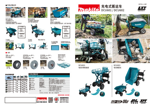
充电式搬运车DCU601电动升降机类型DCU602电动倾卸式90°625 - 1,015mm945 -1,090mm充电式搬运车无段变速电子制动正逆转电子式3速电子恒速缓速启动内置工作灯DCU601Z / DCU602Z行驶速度预估行驶距离连续运行时间(满电量电池)最大负载能力最大爬坡能力轮胎直径手柄高度调节尺寸(长 x 宽 x 高)净重前进:5.0、3.5、1.5 km/h 倒车:1.0 km/h7.2公里(带四个BL1860B电池,在平坦的地面上,关灯,负载300公斤,速度为5.0公里/小时)100分钟(带四个BL1860B电池,在平坦的地面上,关灯,负载300公斤,速度为5.0公里/小时)平地(0-3º):300公斤,斜坡(3-12º):180公斤12°前/ 后: 330 / 210 mm740 / 780 / 820 / 860 / 900 / 940 / 980 mm DCU601:安装托架时,在操作过程中:1,400 x 730 x 820 - 1,260 mmDCU602:安装托架时,在操作过程中:1,480 x 730 x 820 - 1,260 mmDCU601: 145 kg DCU602: 147 kgDCU601 / DCU602DCU603手动倾卸+铲斗DCU604手动倾卸+管架托架DCU605平铲斗设计用于提高卸载效率手动倾卸卸载效率高在携带液体或清洗铲斗时,带帽喷嘴可方便地排出液体铲斗内部没有螺丝,可以使用粘土铲等工具顺利卸载手动倾卸伸缩式装载平台•防锈塑料桶可装载湿物品•内侧底部和正面倾斜,便于倾倒操作适用于箱式或袋装材料•防锈铲斗可装载湿物品•最适合不需要倾卸功能的操作,如在马厩中喂食铲斗容量堆容量200L 满液体容量100L295L 250L管架托架组件部件号 191B67-2仅适用DCU602•管架托架•可变尺寸装载平台充电式搬运车满足专业人士需求智能充电技术DC18RC DC18RDDC18SD 铲斗容量堆容量满液体容量轮胎 330 (单个)部件号 1911K4-7用于草坪和路面•带内胎轮胎•颜色:黑色•包含一个轮胎灰色轮胎 330 (单个)部件号 1911K5-5用于工业场所,如工厂、地板上不希望有黑色轮胎痕迹灰色轮胎 210 (单个)部件号 1911K6-3•带内胎轮胎•颜色:灰色•包含一个轮胎•带内胎轮胎•颜色:灰色•包含一个轮胎用于工业场所,如工厂、地板上不希望有黑色轮胎痕迹附件裸机(电池、充电器另售)DCU601Z / DCU602Z:740mm12°图片: DCU604475mm(在大约30秒内提升到1020毫米。
电动托盘车维修手册-MagnumLiftTrucks.pdf
目录content1 车辆维修安全注意事项Truck mantenance safty precautions (3)2 电动托盘类叉车配置介绍Electric pallet truck models introduction (5)2.1 托盘搬运车Electric pallet truck (5)2.2 托盘堆垛车Electric stacker (5)2.3 平衡重式托盘堆垛车Counter balance stacker (5)3 主要部件介绍Main components introduction (6)3.1 转向控制器Turning controller (6)3.2 驱动控制器Driving controller (9)3.3 仪表Power meter (12)3.4 操纵手柄Operation handle (14)4 电气原理图Electrical diagrams (16)4.1 托盘堆垛车电气原理图Diagram of electric pallet truck (16)4.2 托盘搬运车电气原理图Diagram of electric stacker (17)4.3 托盘搬运车DC电机电气原理图Diagram of DC electric stacker (18)5 车辆故障代码读取Read trouble shooting code (19)5.1 转向系统故障代码读取Trouble shooting code of turning system (19)5.2 驱动系统故障代码读取Trouble shooting code of driving system (19)6 故障代码表Trouble shooting chart (19)6.1 转向系统故障代码表Trouble shooting chart of turning system (20)6.2 交流驱动系统故障代码Trouble shooting of AC controller (Curtis1230) 216.3 直流驱动系统故障代码Trouble shooting of DC controller (Curtis1243) 227 车辆故障排除Trouble shooting (23)7.1 转向系统故障排除Turning system trouble shooting (23)7.2 交流驱动系统故障排除AC driving system trouble shooting (28)7.3 起重系统故障排除Lifting system trouble shooting (33)8 CURTIS手持单元Curtis programmer (36)8.1 CURTIS手持单元介绍Introduction of Curtis programmer (36)8.2 CURTIS手持单元操作Operating instruction of Curtis programmer 379 充电器Charger (38)9.1 充电器介绍Introduction of charger (38)9.2 充电器操作Operation of charger (38)9.3 充电器工作原理How the charger works (39)9.4 充电器常见故障Charger common faults (39)9.5 充电器电路图Diagram of charger (40)9.6 充电器检修Charger maintenance (41)10 车辆必要的定期维护Necessary regular maintenance of the truck (44)10.1 车辆的日常清洁Truck daily clean (44)10.2 重要电气部件维护Important electric components maintenance (44)1 车辆维修安全注意事项Truck maintenance safety precautions●车辆维修必须是专业人员车辆维修人员需要经过电动叉车专业知识培训,未经过培训的人员,请不要擅自维修车辆,防止造成人员伤害和车辆的损坏。
各种吊车技术参数(1)
B
5840
BQ
4800
BX
1500(H=9,12);2000(H=18,24)2500(H=30)
H1
1895
基
H2
170
本
H3
82
mm
尺
H4
525
寸
a
160
b
20 130 96 196 296 396 546 646
746
c
500
d
150
S1
1600(H=9,12);1850(H=18,24);2100(H=30)
1500(H=6~12);2000(H=18~30)
H1
1450
H2
139
H
1451
a
120
b
27 77 177 277
327
422 522 622
722
s1
1730(H=6~12);2000(H=18~30)
2.LH 型电动葫芦桥式起重机(10T)
额定起重量
t
10
操纵形式
地面操纵;操纵室操纵
升起
起升高度
m
9;12;18/6;9;12;18;24;30
工作制度
A5 JC=25%
电源
3-PhaseA.C 三相交流;50Hz;380V
荐用钢轨
kg/m
43
跨度
m 7.5 10.5 13.5 16.5 19.5 22.5 25.5 28.5
31.5
最大轮压
13.1 13.5 14.0 14.6 15.3 16.1 16.9 17.7
YZRS114M-4/5
电动葫芦
HC16
HC16
电动地牛2吨合力电动车 技术参数

电动地牛2吨合力电动车技术参数
电动地牛2吨合力电动车是一款用于物流和仓储领域的电动搬运车,具有高效、环保、节能等特点。
该车辆的技术参数包括以下几个方面:
1. 载重能力,电动地牛2吨合力电动车的载重能力为2吨,能够满足中小型物流仓储场景下的货物搬运需求。
2. 电池参数,该车搭载锂电池,电池容量和续航里程会根据具体型号而有所不同,一般来说,电池容量会在100Ah以上,续航里程可达80公里以上。
3. 动力系统,采用电动驱动,具有零排放、低噪音的特点,能够满足环保要求,同时提供稳定的动力输出。
4. 车辆尺寸,通常情况下,电动地牛2吨合力电动车的车身尺寸约为3.5米×1.2米×1.8米(长×宽×高),具体尺寸也会根据不同型号有所差异。
5. 充电方式,支持快充和慢充两种充电方式,快充一般在2-4
小时内可充满电,慢充则需要6-8小时。
6. 操控性能,配备方向盘、刹车系统、悬挂系统等,操作简便、稳定性好。
总的来说,电动地牛2吨合力电动车作为一款用于物流和仓储
领域的搬运工具,具有较强的载重能力和稳定的动力输出,同时满
足环保节能的要求,适用于各种场景下的货物搬运作业。
flat-jack产品说明书
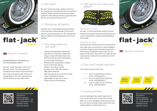
flat-jack products GmbH Innstrasse 885640 PutzbrunnFon +49 89 454577 - 150 Fax +49 89 454577 - 155*****************www.flat-jack.deCongratulations and thank you for choosing flat-jack®!flat-jack ® avoids flat spots on the tires of your automobile. These flat spots arisethrough pressure load during long standing times and can therefore badly reduce your driving pleasure. flat-jack® guarantees the perfect adaption to every shape of tire./// flat-jack®flat-jack® retains the actual condition of the tires over long periods of standing still of your automotive treasures. Please read the instructions and safety guidelines of this manual carefully to guarantee safe and secure operation of the flat-jack® ./// Disclaimer of liabilityIf the flat-jack® is used differently than described in this instruction manual damage of the product, vehicle or even people may occur. The manufacturer takes no liability for damage arising from incorrect handling./// The advantages of• Complete decoupling from the ground.• Best thermic insolation by means of air.• Unique concept with high contact area.• Effective and even pressure distribution over the whole contact area.• Reduction and compensation of lateral forces on the entire chassis.• Simple to use (roll on, roll off).• By means of air: 100% effectiveness.• High quality materials.• High load capacity up to 2,5t per air pillow.• Can be individually combined.• Light weight (0,6 kg), easy to store.•Design serves as centering aids./// flat-jack is not only an air pillow®Membrane conceptflat-jack® is constructed double-walled. The inner membranes guarantee optimal density and the outer cover is responsible for longevity and stabilisation of the shape.Chamber conceptThe special inner chamber structure with special par-tition walls does not only allow an optimal adaption to each tire shape but also distributes the pressure effectively by enlarging the contact area. The uni-queness of flat-jack® also results from reduction and compensation of lateral forces and tensions on the entire chassis./// flat-jack® model overview1 set contains one pair of flat-jack®• Size S: up to tire width 195mm/7,68 inch Art Nr.: 426032833001 2• Size M: up to tire width 255mm/10,04 inch A rt Nr.: 426032833002 9• Size L: up to tire width 345mm/13,58 inch Art Nr.: 426032833003 6/// Getting startedIncorrect handling of this product may result in injury. Check the flat-jack® always before usage. Make sure it is not damaged and that the valves are also correctly functioning. Please read the flat-jack®safety guidelines carefully before use.flat-jack products GmbH Innstrasse 885640 PutzbrunnFon +49 89 454577 - 150 Fax +49 89 454577 - 155*****************www.flat-jack.deMade in Germany Patent pending World noveltyflat-jack®Owner‘s manualOwner‘s manual/// Imortant instructionsThe selected materials for the production of flat-jack® fulfil the highest quality material standards. The construction of a flexible body filled with air is subject to a certain material expansion. As a result there is a minimal loss of pressure after the first inflation with air. Use of the valve caps increases the density. High temperature variation has a negative influence on the density of the valves. For optimal use of flat-jack® it is mandatory to:• Use the valve caps.• Check pressure levels after 3 days.• Additionally check pressure levels at regular • periods.• Avoid temperature variation (use in garagesor closed areas is recommended).Before emptying the flat-jack® make sure that:There are no people directly in front or behind the vehicle. Parking brake is applied. Manual transmission: first gear is engaged. Automatic transmission: “P” is selected (park gear). Slowly and carefully empty the flat-jack at the drain valve./// Technical specificationInside material: PU/PUR membraneOutside material: PU/PUR braid-reinforced Valve: German high quality productOperating pressure: 0.4-0.8 bar/5.8-11.6 psi Maximum pressure: 1.0 bar/14.5 psiMaximum load: verified up to 2,5t per tire air pillowStyle of construction: double-walled high frequency welded/// Storage and cleaningStore flat-jack® pressure-free in a dryenvironment. Use solvent-free detergents for cleaning. Our recommendation: Use a moist cloth and dishwashing liquid./// Returning the flat-jack®In case of returning the flat-jack® please usethe original packaging material to avoid transport damages. The manufacturer does not take any liability for damages caused during transport due to incorrect packaging./// Safety instructionsflat-jack® size has to correspond with tire size.• Size S: up to tire width 195mm/7,68 inch Art Nr.: 426032833001 2• Size M: up to tire width 255mm/10,04 inch A rt Nr.: 426032833002 9• Size L: up to tire width 345mm/13,58 inch Art Nr.: 426032833003 6• Before use a clean and level base is necessary.• Secure the vehicle against rolling away by applying parking brake/placing in gear.• Never use flat-jack® in duplex garages.• In inflating manufacturer’s instructions must be followed.• Inflate flat-jack® axle by axle.•to 11.60 psi•Maximum pressure: 1.0 bar/14.25 psiExcessive pressure prevents transverse movement of the vehicle and therefore eliminates the advantage of reducing chassis strain.• flat-jack® is not a lifting bag and shall not beused to lift heavy loads other than specified in the flat-jack® manual.• flat-jack® is not a swimming aid./// Use of flat-jack®A level base is necessary. Secure the vehicle against rolling away: Parking brake/ placing in gear.2Place empty flat-jack® directly to tires. Lay in front or behind all tires.3Ensure centred tire position. Valves (*) must be accessible from outside.4Carefully roll vehicle on to flat-jack®. Centre tires. Apply parking brake. Manual transmission: Engage first gear. Automatic transmission: Select …P“ (park gear).5Carefully fill flat jack at the inflation valve until vehicle …hovers“ above groud using operating pressures given. Check pressure constantly. Operating pressure variesbetween 0.4 and 0.8 bar according to vehicle weight. Respect maximum pressure of 1.0 bar!67/// To empty the flat-jack®at the vehicleinstructionsMount valve caps.。
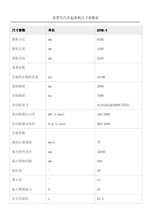
各型汽车起重机尺寸参数表
最高行驶速度 km/h
最小转弯直径 m
最小离地间隙 mm
接近角
°
离去角
°
最大爬坡能力 %
百公里油耗
L
主要性能参数
最大额定总起重 t
量
12550 2500 3380
29400
6200 23200 SC8DK280Q3/WD615.329(国 III) 206/2200??213/2200 1112/1400?1160/1400 75 22 260 16 13 30 ≈37
整机全高(theheightformobilecrane)
mm
3430
重量参数(theweightformobilecrane)
kg
29000
前轴轴荷
kg
6970
后轴轴荷
kg
22030
发动机型号
?SC8DK260Q3
发动机额定功率
kW/(r/min)
192/2200??
发动机额定扭矩
N.m/(r/min) ?1000/1400?????
mm kg kg kg
kW/(r/min) N.m/(r/min)
km/h m mm ° ° % L
t mm m kN.m
3300 26020 7000 19020
75 20 270 16 13 35 ~35
20 3000 3.38 833
基本臂
最长主臂
最长主臂+副臂
支腿纵向距离
支腿横向距离
工作速度参数
km/h mm mm ° ° % L
QY8B.5 9450 2400 3180
10490 2800 7690 XZJ5103JQZ8D89(国Ⅲ) 105/2500 500/1600
叉车控制电路图

一、 概述串励可编程系列控制器,是用在各种电动工业车辆上的串励电机牵引控制器,它可以 完全替代同类进口产品。
具有以下特点:/•基于DSP 技术,高效可靠; /•高频斩波,低噪音: /•具有反接制动功能: /•具有欠压、过压保护功能: /•具有过热保护功能:/•通过内置的可编程参数可与不同电机匹配并实现不同的操作感受: /•外置的LED 灯提供故障诊断。
二、 安装及连线与同类进口产品具有完全相同的功能、特性、接口电路和安装尺寸,无需任何外部改弱电接口回田回国回EE1、 逻辑电源输入2、 互锁输入变即可完美替换。
600A 产品长度方向延长。
安装尺寸3、模式选择开关4、未用5、加速器0-10V6、紧急反向输入7、未用8、未用9、未用10、前进信号输入11、后退信号输入12、未用13、加速器:三线加速器髙端14、加速器:低端15、加速器:0-5V滑动端16、加速器:两线电阻型加速器输入17、主接触器驱动18、前进接触器驱动19、后退接触器驱动20、未用21、未用22、未用23、未用24、紧急反向检查大电流接线端子M-:电机电枢接线端子B-:电源负极接线端子B+:电源正极接线端子A2:电机电枢接线端子典型接线图三、技术参数标称输入电压PO工作频率对散热器电绝缘小)KS:[输入电压(最小)KSI输入电流(无接触器时〉逻辑输入电压低<lv逻辑输入电流匸作环境温度范鬧散热器过热切断散热器欠温切断存储环境规定48v16kHz500v交流(最为16. 8v160mA商>7・5v:10mA-40、C 到50、C85°C-25°CIP54q 3. 9kg (500A型号)尺寸(LXwXH)175mmX83. 5mm (500A 型号)253mmX开关开关流标称电流电电流欠压点型号电池电压限制一分钟额定一小时额定(V) (A) (A)*(A) (V)48V/500A 48 500 500160 2148V/600A 48 600 600200 21*在25匸环境温度下注:控制器参数*j CURTIS兼容,请参照CURTIS同型号说明即可。
JACK 2-1 2 Ton 产品说明书
Model SJ-25QLCapacity 2-1/2 TonThis is the safety alert symbol. It is used to alert you to potential personal injury hazards. Obey all safety messages that follow this symbol to avoid possible injury or death.U.S. Patent No's. 5,755,099 • 5,946,912Pump To Load Service JackOwner's ManualFigure 1 - Model SJ-25QL ComponentsPRePaRaTIOnassembly1. Assemble the 2-piece handle with provided bolt .2. Insert handle into the handle sleeve. Tighten the bolt on handle sleeve to prevent accidental removal of handle while in use.Before Use1. Verify that the product and application are compatible, if in doubt call Tech Service (888) 332-6419.2. Before using this product, read the operator's manual completely and familiarize yourself thoroughly with the product, its components and recognize the hazards associated with its use.3. To familiarize yourself with basic operation, locate and turn the release valve (handle):a. Clockwise until firm resistance is felt to further turning. This is the ‘CLOSed ’ release valve position used to raise the saddle.b. Counter-clockwise, but no more than 1 turn from the closed position. This is the ‘OPen ’ release valve position used to lower the saddle.4. With saddle fully lowered, remove the vent screw. Pump 6 to 8 full strokes. This will help release any pressurized air which may be trapped within the reservoir. Check oil level (refer to Maintenance, page 4). Reinstall vent screw.5. Ensure that jack rolls freely. Raise and lower the unloaded saddle throughout the lifting range before putting into service to ensure the pump operates smoothly. Replace worn or damaged parts and assemblies with authorized replacement parts only.SaFeTY and GeneRaL InFORMaTIOnSave these instructions. For your safety, read, understand, and follow the information provided with and on this jack before using. The owner and operator of this equipment shall have an understanding of this jack and safe operating procedures before attempting to use it. The owner and operator shall be aware that use and repair of this product may require special skills and knowledge. Instructions and safety information shall be conveyed in the operator's native language before use of this jack is authorized. If any doubt exists as to the safe and proper use of this jack, remove from service immediately.Inspect before each use. Do not use if broken, bent, cracked or damaged parts are noted. Any jack that appears damaged in any way, or operates abnormally shall be removed from service immediately. If the jack has been or suspected to have been subjected to a shock load (a load dropped suddenly, unexpectedly upon it), immediately discontinue use until jack has been checked by a factory authorized service center (contact distributor or manufacturer for list of authorized service centers). It is recommended that an annual inspection be done by qualified personnel. Labels and Operator's Manuals are available from the manufacturer.PROdUCT deSCRIPTIOnThis Service Jack is designed to lift, but not support, one end of a vehicle. Immediately after lifting, loads must be supported by a pair of appropriately rated jack stands. This service jack has a unique feature that provides fast, no load lifts to the jacking point, at which time it lifts in approximately 0.75~0.2" increments.NEVER use a hydraulic jack as a stand-alone device. After lifting, immediately support the lifted vehicle with a pair of appropriately rated jack stands. NEVER place any portion of your body beneath the vehicle when lifting OR lowering!SaddleHandle Rear CasterFront WheelLift ArmGreaseNippleOil Filler Screw/Vent Screw on Reservoir (not shown)SPeCIFICaTIOnSModel Capacity Jack Size (L x W x H)Min. HeightMax. HeightSaddle Dia.SJ-25QL2-1/2 Ton29-3/4" x 13-1/4"4"20"5-1/2"OPeRaTIOnLiftinguse hydraulic jack as a stand alone device! ALWAYS transfer the lifted load IMMEDIATELY to a pair of appropriately rated jack stands. NEVER place any portion of your body beneath the vehicle when lifting or lowering!on area of the vehicle as specified by the vehicle manufacturer.1. Follow the vehicle manufacturer’s recommended guidelines for lifting. Engage the emergency brake and chock each unlifted wheel in both directions to prevent inadvertent vehicle movement.2. Close the release valve by turning the handle knob clockwise until firm resistance is felt.3. Refer to the vehicle manufacturer owner’s manual to locate approved lifting points on the vehicle. Center jack saddle under lift point.4. Verify lift point, then pump handle to contact lift point. To lift, pump handle until load reaches desired height.5. Transfer the load immediately to a pair of appropriately rated jack stands.Lowering1. Raise load high enough to clear the jack stands.2. Remove jack stands carefully (always used in pairs).3. Slowly turn the handle knob counter-clockwise, but no more than 1 full turn. If the load fails to lower: a. Use another jack to raise the vehicle high enough to reinstall jack stands.b. Remove the malfunctioning jack and then the jack stands.c. Using the functioning jack to lower the vehicle. 4. After removing jack from under the vehicle, fully lower the saddle to reduce ram exposure to rust and contamination.TROUBLeSHOOTInGSymptomPossible CausesCorrective actionJack will not lift load• Release valve not tightly closed • Load is too heavy• Ensure release valve tightly closed • Consider higher capacity jack Jack will lift, but not maintain pressure• Release valve not tightly closed • Hydraulic unit malfunction • Ensure release valve tightly closed • Discontinue use, contact technical serviceJack will not lower after unloading • Reservoir overfilled • Linkages binding • Drain fluid to proper level• Clean and lubricate moving parts Poor lift performance• Fluid level low• Hydraulic unit malfunction • Ensure proper fluid level• Discontinue use, contact technical serviceWill not lift to full extension• Fluid level low• Ensure proper fluid levelPaint contains lead!DO NOT sand or grind painted surface!MaInTenanCeImportant: Use only good grade hydraulic jack oil. Avoid mixing different types of fluid and NEVER use brake fluid, turbine oil, transmission fluid, motor oil or glycerin. Improper fluid can cause premature failure of the jack and the potential for sudden and immediate loss of load. We recommend Mobil DTE 13M or equivalent.adding oil1. With saddle fully lowered set jack in its upright, level position. Remove vent screw.2. Fill with oil until ~3/16" above the inner cylinder as seen from the oil filler hole. Reinstall vent screw. Changing oilFor best performance and longest life, replace the complete fluid supply at least once per year.1. With saddle fully lowered, remove vent screw.2. Lay the jack on its side and drain the fluid into a suitable container.note. Dispose of hydraulic fluid in accordance with local regulations.3. Fill with oil until ~3/16" above the inner cylinder as seen from the oil filler hole. Reinstall vent screw.LubricationA periodic coating of light lubricating oil to pivot points, axles and hinges will help to prevent rust and assure that wheels, casters and pump assemblies move freely.CleaningPeriodically check the pump piston and ram for signs of rust or corrosion. Clean as needed and wipe with an oily cloth.note: Never use sandpaper or abrasive material on these surfaces!StorageWhen not in use, store the jack with saddle fully lowered.17841465231119121315151616171819AAABCDEFGHHJJKLLM NM NNQPRST U VW212** Replacement requires special skills, knowlege, and equipment. Only authorized service center may perform the repair and/or replacement of these items.Replacement Parts for models SJ-25QL:Item Part no. descriptionQty 1G610-11000-000Hydraulic Power Unit 12G640-90010-K02Front Wheel Assy.23G610-90009-K03Rear Caster Assy.24G610-00016-000Saddle15G62S-03300-200Vent Screw Assy.16G610-90009-K06U-joint Assy.17G610-90009-K01Handle (2 pc.)18G933-0001-000Handle Grip 195102-08016-000Bolt, M8x16110G931-00009-000Spring, Handle Sleeve (Right)111G610-00008-000Spring, Handle Sleeve (Left)112G931-00003-000Spring, Lift Arm 213G610-03005-000Spring, Pump 1145404-04040-000Retainer, 4x40115G610-00009-000Handle Bolt 2165303-00020-000Lock Washer, M20217G931-00010-000Bolt, M124185303-00012-000Lock Washer, M12419G610-00013-000Cover120G610-90009-K02Pump Piston Assembly 121G610-06000-000Handle Fork 1**G6900S-113Repair Kit-Item DescriptionQty A O-ring, D7.8x2.654B Back-up Ring 1C O-ring, D15x2.651D U-cup1E Back-up Ring 1F O-ring, D44.5x2.41G Back-up Ring 1H O-ring, D63x2.652J O-ring, D8.2x2.42K O-ring, D31.6x3.51L Back-up Ring 2M Steel Ball, D9.522N Steel Ball, D6.355P Back-up Ring 1Q O-ring, D6x31R O-ring, D7.2x2.651S Back-up Ring 2T O-ring, D17.6x2.52U Back-up Ring 1V O-ring, D25x2.651W Steel Ball, D6.741(in #5)O-ring, D8.8x1.91Repair Kit ContentsRePLaCeMenT PaRTS(refer to page 5 & 6)Not all components of the jack are replacement items, but are illustrated as a convenient reference of location and position in the assembly sequence. When ordering parts, please give the Model number, part number and parts description. Call or write for current pricing: SFA Companies 10939 N. Pomona Ave. Kansas City, MO 64153, ************************************:(888)332-6419Fax:(816)891-6599One YeaR LIMITed WaRRanTYFor a period of one (1) year from date of purchase, SFA Companies will repair or replace, at its option, without charge, any of its products which fails due to a defect in material or workmanship under normal usage. This limited warranty is a consumer's exclusive remedy.Performance of any obligation under this warranty may be obtained by returning the warranted product, freight prepaid, to SFA Companies Warranty Service Department, 10939 N. Pomona Ave., Kansas City, MO 64153.Except where such limitations and exclusions are specifically prohibited by applicable law, (1) THE CONSUMER'S SOLE AND EXCLUSIVE REMEDY SHALL BE THE REPAIR OR REPLACEMENT OF DEFECTIVE PRODUCTS AS DESCRIBED ABOVE. (2) John Dow SHALL NOT BE LIABLE FOR ANY CONSEQUENTIAL OR INCIDENTAL DAMAGE OR LOSS WHATSOEVER. (3) ANY IMPLIED WARRANTIES, INCLUDING WITHOUT LIMITATION THE IMPLIED WARRANTIES OF MERCHANTABILITY AND FITNESS FOR A PARTICULAR PURPOSE, SHALL BE LIMITED TO ONE YEAR, OTHERWISE T HE REPAIR, REPLACEMENT OR REFUND AS PROVIDED UNDER THIS EXPRESS LIMITED WARRANTY IS THE EXCLUSIVE REMEDY OF THE CONSUMER, AND IS PROVIDED IN LIEU OF ALL OTHER WARRANTIES, EXPRESS OR IMPLIED. (4) ANY MODIFICATION, ALTERATION, ABUSE, UNAUTHORIZED SERVICE OR ORNAMENTAL DESIGN VOIDS THIS WARRANTY AND IS NOT COVERED BY THIS WARRANTY.Some states do not allow limitations on how long an implied warranty lasts, so the above limitation may not apply to you. Some states do not allow the exclusion or limitation of incidental or consequential damages, so the above limitation or exclusion may not apply to you. This warranty gives you specific legal rights, and you may also have other rights, which vary from state to state.SFA Companies10939 N. Pomona Ave. Kansas City, MO 64153888-332-6419***************************Contact:SFA Companies10939 N. Pomona Ave. Kansas City, MO 64153, U.S.A.Tel:(888)332-6419 Fax:(816)891-6599***************************。
TC.3000面板搬运车说明书
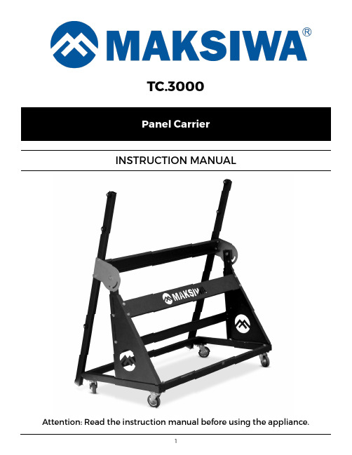
TC.3000Panel CarrierINSTRUCTION MANUALAttention: Read the instruction manual before using the appliance.Important information you should know:• The images in this manual are illustrative and are meant to demonstrate the correct operation of your product, there may be small changes in relation to the images.CAUTION:If maintenance is required, replace only with identical parts. Also, repair or replace faulty wiring.• Keep a clean work surface. Cluttered areas and work surfaces invite accidents.• Do not use the Panel Carrier in hazard ous environments. Do not use the machine in d amp or wet locations or areas that are exposed to rain. Keep in a well-lit work area.• Keep children away from machines. Visitors should be kept at a safe distance from the work area.• Make the workplace child proof making use of padlocks.• Do not force tools. T ools should be used for the intended use only.• Use appropriate equipment. Do not wear loose clothing, jewelry, or other accessories that could get caught in moving parts.• It is recommended wearing shoes with non-slip soles. Use protection for the hair in order to hold them.• Always wear safety glasses. Also use hearing protection.• Do not overreach on the equipment. Maintain balance and feet in comfortable position at all times.• Keep all tools in order. Keep tools sharp and clean for better and safer performance. Follow the instructions for lubricating and changing accessories.• Check for damaged parts before continuing the use of Panel Carrier. Any part that is damaged should be examined carefully to determine its proper operation and perform its function properly. Check the alignment of moving parts, breakage of parts, mounting and any other condition that may affect its operation. Any part that is damaged should be repaired or replaced immediately.CAUTION: Failure to heed these warnings may result in severe injury or damage to the machine.• Always use safety glasses. Also use face or dust mask if cutting operation is dusty. Everyday eyeglasses only have impact resistant lenses, they are NOT safety glasses.• Make sure that the knobs and screws are properly tightened and safe before starting any operation. WARNING: Some dust created by the act of sanding, cutting, grind ing, d rilling and other construction-related activities contains chemicals that can cause cancer, birth d efects or other reprod uctive harm. Some examples of these prod ucts are: Lead-based paint; crystal silica bricks, concrete and other masonry products; and arsenic and chromium from chemically treated wood.Do not operate the machine unless the guards are in their proper places. Always use protective goggles. FamiliarizationUse the pictures and read the d escriptions carefully to familiarize yourself with its components. The next section will deal with the necessary ad justments for the proper functioning of the machine. You should know these parts and where they belong. SpecificationsThe TC.3000 Panel Carrier was mad e to facilitate the d ay-to-d ay tasks of the mod ern wood worker. Its d urable structure and4-wheels allow anyone to ALWAYS USE PROPER PROTECTIVEEQUIPMENTS TO OPERATE THISMACHINE.Online Support: Visit our YouTube Channel to find several videos that will assist you with Maksiwa machines. Use the QRCode.WARNINGSeasily carry up to 2 full sheets of wood at once. It has an adjustable height mechanism making it easy to work in conjunction with virtually any wood working equipment you have, such as panel and table saws.With a carrying capacity of up to 254 pounds, this will help you increase prod uctivity, red uce injuries from carry heavy loads, and it only requires one person to operate it.Minimum table height: 33”Maximum table height: 37”Equipment dimension: 43” x 49” x 28”Maximum capacity: 254 LbsMaximum panel size: 108” x 1” x 72”Weight: 70.5 LbsTransport and InstallationBy ergonomic issues, this equipment must be carried by at least two people.For packaging purposes, the machine is not fully assembled . If you notice any d amage caused by transportation, while you open the package, notify your supplier immed iately. Do not operate the machine.Please d ispose the packaging in an environmental friendly way.H - Left bar panel support;I - Right bar panel support;J - Support panel section set;K - Support height regulation;L - Structure cross reinforcement;M - T op reinforcement;N - Structure upper reinforcement.A - Left and right structures;B - Support panel;C - Base structure wheels;D - Mobile rubber wheels 3”;E - Crossbar rear structure;F - Front structure;G - Side structure crossbar assembly;Kit 1:- Left and right structures - Crossbar rear structure - Front structure- Side structure crossbar assembly - Base structure wheels - Mobile rubber wheels 3”- Screws, nuts, washers, and boltsYou will receive the pieces in 3 kits with their respectivescrews.Kit 3:- Left bar panel support - Right bar panel support - T op reinforcement- Support panel section set- Screws, nuts, washers, and boltsKit 2:- Support panel- Support height regulation- Structure upper reinforcement - Structure cross reinforcement - Screws, nuts, washers, and boltsFirst, assemble the kit 1:1) Mount the panel carrier base with the drive wheels.T ake the structures and align them at the vertices of the base. After that, place the drive wheels and screwthem.Detail2) Mount the left and right structures.DetailReady! Kit 1 is properly mounted.DetailDetailNow, assemble the pieces of Kit 2:1) Mount the structure cross reinforcement.2) Mount the structure upper reinforcement.3) Mount the side structure crossbar assembly.Detail4) Mount the support panel.DetailDetailReady! Kit 2 is properly assembled.Finally, assemble Kit 3:1) Mount the left and right bar panel support.2) Mount the structure cross reinforcement.DetailDetail3) Mount the support panel section set.4) Install all pulleys.Kit 3 is assembled.Read y! The TC.3000 Panel Carrier is subject to assembly. Before using, remember all safety andinstallation regulations.WARRANTY TERMSMAKSIWA assures the owner that their equipment, identified by the Serial number issued on the Warranty T erms.The equipment und er warranty, for two (2) years, is as followed:1. The warranty period begins on the date of the Warranty T erms below.2. Within the warranty period, the manual labor and the components replaced by manufacturing d efect will be provid ed for free as long as d uly proved by Maksiwa Service.3. Third-party manufacturing equipment that makes up the MAKSIWA equipment (such as motors, electrical equipment, belts etc.) are subject to the terms and conditions of warranty of their respective manufacturers.4. In case an exchange of machine is needed, please return the defective part or machine to MAKSIWA.5. All workplace adaptations for the equipment are under the responsibility of the machine owner.6. If you notice any d efect or malfunction when receiving the equipment, get in touch immed iately with the manufacturer or Dealer. Do not turn it on.7. Not included in this warranty is any technical visits aimed at cleaning or adjustments caused by wear, resulting from normal use of the equipment.8. The warranty does not cover problems caused by mistreatment, carelessness, misuse or inappropriate use of the functions designed for this equipment in this manual, as well as poorly executed operations by untrained operators to operate it.9. MAKSIWA is not responsible for lost productivity, direct or indirect damages caused to the owner of the equipment or to third parties, or any other expense, including lost profits.10. Even under warranty, you may lose its validity as follows:a) Application of non-original components;b) Alteration of its original features;c) Lack of proper maintenance;d) Improper use of the equipment;e) Change in equipment or electronic connections;f) Damage caused by mechanical shock or exposure to unsuitable conditions (humidity, salt spray, corrosive agents, etc.);g) Damage caused by bad weather (floods, flooding, lightning, power outages etc.).For your safety, trust the repairs, maintenance and ad justments (includ ing inspection and replacement) for technical assistance recommended by MAKSIWA, always use genuine spare parts and accessories, reassembling to its original machine the same way.Maksiwa International Inc.4100 N Powerline Rd, Suite D1Pompano Beach - Florida - USAZIP CODE: 3307316 19 152026 27 17 281825 2422 21 23 332 1013 1211 18 144 5 6 7 928HEX SCREW M8X16 ZB 227 SCREW M10X25 ZB 226 FLAT WASHER M10 ZB 225 SCREW AUTO PILOT PARLOCK M10 224FLAT WASHER 3/8 ZB223 SCREW M8 X 20 ZB 222 SUPPORT PANEL 221 SCREW AUTO PILOT PARLOCK M8 820 PA 6.6 BLACK 8X9X30 1219 SCREW M8 X 60 ZB 618 SUPPORT PANEL SECTION SET 117 LEFT BAR PANEL SUPPORT 116 RIGHT BAR PANEL SUPPORT 115TOP REINFORCEMENT 114FRONT SUSPENSION LOWER TRAY BRACKET 213 STRUCTURE UPPER REINFORCEMENT 112 STRUCTURE CROSS REINFORCEMENT 111 LEFT STRUCTURE 110 RIGHT STRUCTURE 19 FRONT STRUCTURE 18 CROSSBAR REAR STRUCTURE 17 HEX SCREW M8X12 ZB 406 FLAT WASHER M8 ZB 525 MOBILE RUBBER WHEELS 3” 44 BASE STRUCTURE WHEELS 43 HEX SCREW M8 ZB 122 SUPPORT HEIGHT REGULATION 21 SIDE STRUCTURE CROSSBAR ASSEMBLY 2Nº REF.NAMEQTY.PANEL CARRIER1。
ESCO 2 吨伸缩式传动 jack 产品说明书
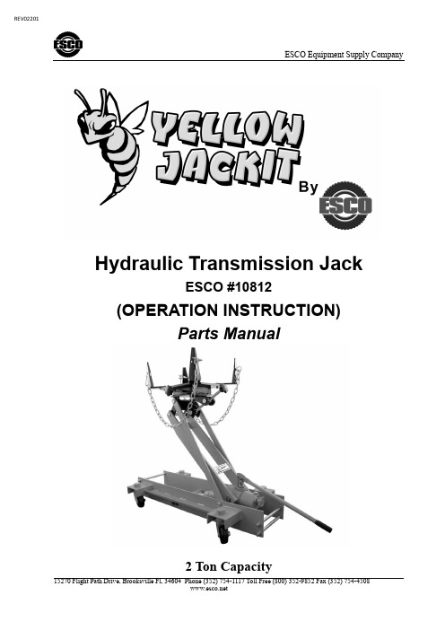
ESCO Equipment Supply CompanyHydraulic Transmission JackESCO #10812(OPERATION INSTRUCTION)Parts Manual2 Ton CapacityREV02201Operating ProcedureExhausting•During shipment and handling, especially after a long storage, air probably gets into the hydraulic system, causing poor lifting performance. Exhaust any air from the system before use. Here follow the methods.•Close release valve (turn knob clockwise as shown). Loosen the air vent plug on the filler, then operate handle until the empty saddle gets to the highest.•Open the release valve (turn knob counterclockwise). While holding the empty saddle down, operate handle rap i dly several times in order to exhaust the air in the system, then press the air vent plug tightly.Lifting•Turn the knob clockwise until release valve closes. Do not over tighten the va l ve.•Place jack directly and centrally under object to be lifted. Operate the handle up and down within an angle of 60°. The jack can take up load immediately.•While lifting very heavy objects, the angle to operate handle must be w i thin the limits of 45° so as to avoid damaging parts with the rapid increase of the operating force. (full 360orotating pump handle operates in any pos i tion)•After raising jack to required height: use jack stand(s) to hold load.Transmission•Fix load tightly on the saddle with chains.•Turn the release valve counterclockwise in order to lower the load to lower position (About at the midpoint of the whole lifting height).•The four handlebars on jack (as shown in the diagram) are used to move jack in any direct i on on level solid surfaces.Saddle Adjusting•For safe and proper use, the saddle can be adjusted according to the load size and angle degrees while d i sassembling (As shown in the diagram).•Loosen the four bolts on saddle, adjust the four retaining plate ass embl y parts to proper position, then twist bolts tightly. The saddle side adjustment is within the limits as shown in the specifications.•Adjust the two regulating bolts on the saddle, and then the saddle can be side titled within the limits as shown in the specifications. The two bolts must be adjusted simultaneously and harmoniously in order to let the saddle stay in required angle and not away.•Turn the adjusting hand wheel under saddle. Then the saddle can be titled withi n the limits from forward to back as shown in the specificat i ons.release valve too fast, or saddle will go down quickly and do damages to load.Oiling•If jack needs re-oiling, take out the air vent plug, inject mach i ne hydraulic oil into the plug. At the same time operate the hand l e for 3 to 5 times in order to guarantee the i nner hydraulic system full of oil. When oil is on a level with the edge under the oil-filling hole, stop oiling and press the air vent plug tightly.Maintenance InstructionBefore operating the jack, lubricate points (1) to (5) indicated in the diagram:A. Wheels: Use light oil on axles and caster bearings.B. Saddle and linkages: Use light oil on all moving pivoting parts.C. Lifting arm: Inject grease into moving parts.D. Handle: Use light oil on moving parts.E. Linkage between handle and plunger. Use grease to lubricate it.Check the hydraulic system: every 4 months to make sure it is free from corrosion. If corrosion is present, clean the parts and remove rust, then re-oil according to the above-mentioned oiling method. Always use good quality hydraulic jack oil. Do not mix the type of oil. When filling with hydraulic oil do not permit dirt or any other substance to enter the hydraulic system.Always store the jack with saddle fully Lowered and with release valve open.Capacity Lift Range Saddle Size Adjustment Castor ChassisSize SaddleTiltNet Weight#10812 Tons Low High Min. Max. DLA. Length Width Lbs.2 9” 35” 12.6” x 7.5” 16.5” x 11.4” 4” 44.7” 26” 297 lbs.#10812 PARTS BREAKDOWN AND PARTS LIST#10812 PARTS BREAKDOWN AND PARTS LIST (cont.)。
KION GROUP AG 电动货运车型号说明书
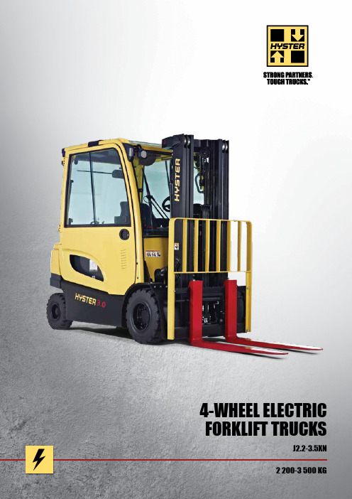
2 200-3 500 KGJ2.2-3.5XN 4-WHEEL ELECTRIC FORKLIFT TRUCKS1.1 Manufacturer (abbreviation) 1.2 Manufacturer’s type designitionModel1.3 Drive: electric (battery or mains), diesel, petrol, fuel gas 1.4 Operator type: hand, pedestrian, standing, seated, order-picker 1.5 Rated capacity / Rated load Q (kg)1.6 Load centre distancec (mm)1.8 Load distance, centre of drive axle to fork x (mm)1.9 Wheelbasey (mm)2.1 Service weight r kg 2.2 Axle loading, laden front/rear r kg 2.3 Axle loading, unladen front/rear r kg3.1 Tyres: L = pneumatic, V = cushion, SE = Pneumatic Shape Solid 3.2 Tyre size, front 3.3 Tyre size, rear3.5 Wheels, number front/rear (x = driven wheels) 3.6 Tread, front * b 10 (mm)3.7 Tread, rearb 11 (mm)5.1 Travel speed, laden / unladen r km/h 5.2 Lift speed, laden / unladen m/sec 5.3 Lowering speed, laden / unladenm/sec5.5 Drawbar pull, laden / unladen, 60 minute rating ** N 5.6 Maximum drawbar pull laden / unladen, 5 minute rating*** N 5.7 Gradeability laden / unladen, 30 minute rating **** † %5.8 Maximum gradeability laden / unladen *** † %5.9 Acceleration time, laden / unladen 10m r sec5.10 Service brake6.1 Drive motor rating S2 60 min kW 6.2 Lift motor rating at S3 15%kW 6.3 Battery according to DIN 43531/35/36 A, B, C, no 6.4 Battery voltage/nominal capacity K5 V/Ah 6.5 Battery weight (min/max)kg6.6 Energy consumption according to VDI cycle À kWh/h @Nr of Cycles8.1 Drive control10.1 Operating pressure for attachments bar 10.2 Oil volume for attachments G l/min 10.3 Hydraulic oil tank, capacity l10.7 Sound pressure level at the driver’s seat J dB(A)10.8Towing coupling, type DINJ2.2XN J2.5XN-717 J2.5XN-861AdvanceAdvanceAdvance Electric (battery) Electric (battery) Electric (battery)SeatedSeated Seated 2200 2500 2500 500 500 500 419 419 419 1606 1606 1750 HYSTER HYSTER HYSTER4520 4520 493057399776211805628311442279 2236 2279 2236 2469 2458 SE SE SE 23 x 10 - 12 23 x 10 - 12 23 x 10 - 1218 x 7 - 818 x 7 - 818 x 7 - 82X 2 2X 2 2X 2 938 1054 938 1054 938 1054 992 992 992 18.0 18.0 18.0 18.0 18.0 18.0 0.40 0.63 0.38 0.63 0.38 0.63 0.57 0.5 0.57 0.51 0.57 0.51 5468 5773 5591 5726 5591 5726 18045 19052 18451 18897 18451 18897 10 14 9 13 9 13 26 39 24 35 24 35 4.42 4.11 4.45 4.11 4.45 4.11 Hydraulic Hydraulic Hydraulic2 x 10.02 x 10.02 x 10.016.016.0 16.043536A43536A 43536A 80 560 80 560 80 700 1480 1635 1480 1635 1770 1956 6.68 7.00 7.89AC electronicAC electronic AC electronic 155 155 155 20-40 20-40 20-40 29.3 29.3 29.3 67 67 67 PinPinPinD I S T I N G U I S H I N G M A R K SW E I G H T ST Y R E S / C H A S S I SD I ME N S I O N SP E R F O R M A N C E D A T AE L E C T R I C E N G I N EA D D I T I O N A L D A T AJ2.2XN, J2.5XN, J3.0XN, J3.5XN ADVANCE4.1 Tilt of mast/fork carriage forward/backward a / b (°)4.2 Height, mast loweredh 1 (mm)4.3 Free lift ¶ h 2 (mm)4.4 Lift ¶ h 3 (mm)4.5 Height, mast extended ª h 4 (mm)4.7 Height of overhead guard (cabin) n h 6 (mm)4.7.1 Cab height (open cab)4.8 Seat height relating to SIP/stand height £ h 7 (mm)4.12 Coupling height h 10 (mm)4.19 Overall lengthl 1 (mm)4.20 Length to face of forks ± l 2 (mm)4.21 Overall width * b 1/b 2 (mm)4.22 Fork dimensions DIN ISO 2331 s/e/l (mm)4.23 Fork carriage ISO 2328, class/type A, B4.24 Fork carriage width l b 3 (mm)4.31 Ground clearance, laden, below mast m 1 (mm)4.32 Ground clearance, centre of wheelbase m 2 (mm)4.33 Load dimension b 12 × l 6 crossways b 12 × l 6 (mm) 4.34Aisle width predetermined load dimensionsA st (mm)4.34.1 Aisle width for pallets 1000 × 1200 wide u A st (mm)4.34.2 Aisle width for pallets 800 × 1200 long u A st (mm)4.35 Turning radius W a (mm)4.36 Internal turning radiusb 13 (mm)4.41 90° intersecting aisle (With pallet W = 1200mm, L = 1000mm) (mm)4.42 Step Height (from ground to running board) « (mm)4.43 Step Height(mm)5 5 5 5 5 5 2192 2192 2192 100 100 100 3350 3350 3350 3960 3960 3960 2193 2193 2193 2206 2206 22061070 1070 1070 262 262 262 3336 3336 3480 2336 2336 2480 1173 1289 1173 1289 1173 1289 4010010004010010004010010002A 2A 2A 1067 1067 1067 83 83 83 137 137 1371200 x 10001200 x 10001200 x 10003613 3613 3750 3613 3613 3750 3766 3766 3906 1931 1931 2073 173 173 189 **** **** 2043706 / 810706 / 810706 / 810475 475 475EQUIPMENT & WEIGHT:Weights (line 2.1) are based on the following specifications:Complete truck with 3 390 mm (J2.5-2.5XN) or 3 200 mm (J3.0-3.5XN) 2-stage limited free lift mast, standard carriage and 1000 mm forks with load backrest with extended shift on with DIN battery configuration, standard seat and overhead guard and pneumatic shaped solid drive and steer tyres.5000 5320 2.1715784178719422.22560 2438 2508 2805 2.3 SE SE 3.123 x 10 - 12 23 x 10 - 12 3.218 x 7 - 818 x 7 - 83.3 2X 2 2X 2 3.5 938 1054 938 1054 3.6992 9923.717.0 18.0 16.0 18.0 5.1 0.33 0.59 0.31 0.59 5.2 0.56 0.46 0.58 0.46 5.3 5441 5588 5478 5720 5.5 17956 18441 18076 18875 5.6 8 12 7 12 5.7 22 34 20 32 5.8 4.56 4.18 4.60 4.23 5.9 Hydraulic Hydraulic 5.102 x 10.02 x 10.06.116.016.0 6.243536A43536A6.380 700 80 700 6.4 1770 1956 1770 1956 6.5 8.66 10.03 6.6AC electronicAC electronic 8.15 5 5 5 4.1WEIGHTSTYRES / CHASSISPERFORMANCE DATAELECTRIC ENGINE NOTE :Specifications are affected by the condition ofthe vehicle and how it is equipped, as well as the nature and condition of the operating area. If these specifications are critical, the proposed application should be discussed with your dealer.r Max. battery ¶ Bottom of forks ª Without load backrest£ F ull suspension in compressed positionspecified. Add 40 mm for nominal position. Add 104 mm for battery side removal option l Add 28 mm with load backrestn h 6 subject to +/- 5 mm tolerance.Add 20mm with cab option.Add 104mm for battery side removal option. Add 124mm for battery side removal with cab option« Vertical/horizontal battery removal± With sideshift carriage add 32mm forJ2.2XN - J2.5XN-717, 34mm forJ2.5XN-861 L WB, 33mm for J3.0XN, 32mm for J3.5XNu S tacking aisle width (lines 4.34.1 & 4.34.2)is based on the VDI standard calculation as shown on illustration. The British Industrial T ruck Association recommends the addition of 100 mm to the total clearance (dimension a) for extra operating margin at the rear of the truck.† G radeability figures (lines 5.7 & 5.8)are provided for comparison of tractiveperformance, but are not intended to endorse the operation of the vehicle on the stated inclines. Follow instructions in the operating manual regarding operation on inclines.r H iP Performance settings À eLo Performance settingsG Maximum flow set through dash display.J L PAZ , measured according to the test cyclesand based on the weighting values contained in EN12053TABLES KEY:< Add 666mm with load backrest extension.m Deduct 666mm with load backrest extension.¨ Add 684mm with load backrest extension Ò Deduct 684mm with load backrest extension.w Add 583mm with load backrest extension. æ Deduct 583mm with load backrest extension.« Add 601mm with load backrest extension.Þ Deduct 601mm with load backrest extension.r Nominal Battery compartment length.¬ W ide tread required. Standard tread possiblebut with reduced capacity. Contact your lift truck dealer ( A lternative capacities available with pneumatictyres. Contact your lift truck dealer. v Max fork height = h 3+s ± Freelift (top of forks) = h 2+sNOTICECare must be exercised when handlingelevated loads. When the carriage and/or load is elevated, truck stability is reduced. It is important that mast tilt in either direction be kept to a minimum when loads are elevated Operators must be trained and adhere to the instructions contained in the Operating Manual.Hyster products are subject to change without notice. Lift trucks illustrated may feature optional equipment.Safety:This truck conforms to the current EU requirements.J2.2XN, J2.5XN, J3.0XN, J3.5XN ADVANCE+1.1 Manufacturer (abbreviation) 1.2 Manufacturer’s type designitionModel1.3 Drive: electric (battery or mains), diesel, petrol, fuel gas 1.4 Operator type: hand, pedestrian, standing, seated, order-picker 1.5 Rated capacity / Rated load Q (kg)1.6 Load centre distancec (mm)1.8 Load distance, centre of drive axle to fork x (mm)1.9 Wheelbasey (mm)2.1 Service weight r kg 2.2 Axle loading, laden front/rear r kg 2.3 Axle loading, unladen front/rear r kg3.1 Tyres: L = pneumatic, V = cushion, SE = Pneumatic Shape Solid 3.2 Tyre size, front 3.3 Tyre size, rear3.5 Wheels, number front/rear (x = driven wheels) 3.6 Tread, front * b 10 (mm)3.7 Tread, rearb 11 (mm)5.1 Travel speed, laden / unladen r km/h 5.2 Lift speed, laden / unladen m/sec 5.3 Lowering speed, laden / unladenm/sec5.5 Drawbar pull, laden / unladen, 60 minute rating ** N 5.6 Maximum drawbar pull laden / unladen, 5 minute rating*** N 5.7 Gradeability laden / unladen, 30 minute rating **** † %5.8 Maximum gradeability laden / unladen *** † %5.9 Acceleration time, laden / unladen 10m r sec5.10 Service brake6.1 Drive motor rating S2 60 min kW 6.2 Lift motor rating at S3 15%kW 6.3 Battery according to DIN 43531/35/36 A, B, C, no 6.4 Battery voltage/nominal capacity K5 V/Ah 6.5 Battery weight (min/max)kg6.6 Energy consumption according to VDI cycle r kWh/h @Nr of Cycles8.1 Drive control10.1 Operating pressure for attachments bar 10.2 Oil volume for attachments G l/min 10.3 Hydraulic oil tank, capacity l10.7 Sound pressure level at the driver’s seat J dB(A)10.8Towing coupling, type DINJ2.2XN J2.5XN-717 J2.5XN-861Advance+Advance+Advance+ Electric (battery) Electric (battery) Electric (battery)SeatedSeated Seated 2200 2500 2500 500 500 500 419 419 419 1606 1606 1750 HYSTER HYSTER HYSTER4670 4870 48605640122461141254618311672018 2646 1805 3063 2067 2783 SE SE SE 23 x 10 - 12 23 x 10 - 12 23 x 10 - 1218 x 7 - 818 x 7 - 818 x 7 - 82X 2 2X 2 2X 2 938 1054 938 1054 938 1054 992 992 992 21.0 21.0 21.0 21.0 21.0 21.0 0.52 0.72 0.49 0.72 0.49 0.72 0.57 0.51 0.57 0.51 0.57 0.51 6015 6235 6037 6185 6037 6185 19849 20576 19927 20409 19927 20409 11 16 10 14 10 14 28 42 26 38 26 38 4.04 3.71 4.04 3.71 4.04 3.71 Hydraulic Hydraulic Hydraulic2 x 10.02 x 10.02 x 10.024.024.0 24.043536A43536A 43536A 80 560 80 560 80 700 1480 1635 1480 1635 1770 1956 7.51 7.87 8.86AC electronicAC electronic AC electronic 155 155 155 20-40 20-40 20-40 29.3 29.3 29.3 68 68 68 PinPinPinD I S T I N G U I S H I N G M A R K SW E I G H T ST Y R E S / C H A S S I SD I ME N S I O N SP E R F O R M A N C E D A T AE L E C T R I C E N G I N EA D D I T I O N A L D A T A4.1 Tilt of mast/fork carriage forward/backward a / b (°)4.2 Height, mast loweredh 1 (mm)4.3 Free lift ¶ h 2 (mm)4.4 Lift ¶ h 3 (mm)4.5 Height, mast extended ª h 4 (mm)4.7 Height of overhead guard (cabin) n h 6 (mm)4.7.1 Cab height (open cab)4.8 Seat height relating to SIP/stand height £ h 7 (mm)4.12 Coupling height h 10 (mm)4.19 Overall length l 1 (mm)4.20 Length to face of forks ± l 2 (mm)4.21 Overall width *b 1/b 2 (mm)4.22 Fork dimensions DIN ISO 2331 s/e/l (mm)4.23 Fork carriage ISO 2328, class/type A, B4.24 Fork carriage width l b 3 (mm)4.31 Ground clearance, laden, below mast m 1 (mm)4.32 Ground clearance, centre of wheelbase m 2 (mm)4.33 Load dimension b 12 × l 6 crossways b 12 × l 6 (mm) 4.34Aisle width predetermined load dimensionsA st (mm)4.34.1 Aisle width for pallets 1000 × 1200 wide u A st (mm)4.34.2 Aisle width for pallets 800 × 1200 long u A st (mm)4.35 Turning radius W a (mm)4.36 Internal turning radiusb 13 (mm)4.41 90° intersecting aisle (With pallet W = 1200mm, L = 1000mm) (mm)4.42 Step Height (from ground to running board) « (mm)4.43 Step Height(mm)5 5 5 5 5 5 2192 2192 2192 100 100 100 3350 3350 3350 3960 3960 3960 2193 2193 2193 2206 2206 22061070 1070 1070 262 262 262 3336 3336 3480 2336 2336 2480 1173 1289 1173 1289 1173 1289 4010010004010010004010010002A 2A 2A 1067 1067 1067 83 83 83 137 137 1371200 x 10001200 x 10001200 x 10003613 3613 3750 3613 3613 3750 3766 3766 3906 1931 1931 2073 173 173 189 **** **** 2043706 / 810706 / 810706 / 810475 475 4755EQUIPMENT & WEIGHT:Weights (line 2.1) are based on the following specifications:Complete truck with 3 390 mm (J2.5-2.5XN) or 3 200 mm (J3.0-3.5XN) 2-stage limited free lift mast, standard carriage and 1000 mm forks with load backrest with extended shift on with DIN battery configuration, standard seat and overhead guard and pneumatic shaped solid drive and steer tyres.1.1J3.0XN J3.5XN 1.2Advance+Advance+Electric (battery) Electric (battery) 1.3SeatedSeated 1.4 3000 3500 1.5 500 500 1.6 431 431 1.8 1750 1750 1.9 HYSTER HYSTER 5300 5370 2.170551244775211152.22090 3209 2209 3158 2.3 SE SE 3.123 x 10 - 12 23 x 10 - 12 3.218 x 7 - 818 x 7 - 83.3 2X 2 2X 2 3.5 938 1054 938 1054 3.6992 9923.719.5 21.0 18.0 21.0 5.1 0.42 0.63 0.37 0.63 5.2 0.56 0.46 0.58 0.46 5.3 5877 6035 5918 6177 5.5 19393 19916 19522 20385 5.6 9 13 8 13 5.7 24 37 22 35 5.8 4.14 3.78 4.19 3.83 5.9 Hydraulic Hydraulic 5.102 x 10.02 x 10.06.124.024.0 6.243536A43536A6.380 700 80 700 6.4 1770 1956 1770 1956 6.5 8.66 10.03 6.6AC electronicAC electronic 8.1155 155 10.1 20-40 20-40 10.2 29.3 29.3 10.3 68 68 10.7 PinPin10.85 5 5 5 4.1 2192 2192 4.2 100 100 4.3 3155 3155 4.4 3865 3865 4.5 2193 2193 4.7 2206 2206 4.7.1 1070 1070 4.8 262 262 4.12 3492 3570 4.19 2492 25704.201173 1289 1173 1289 4.21 50 120 1000 50 120 1000 4.223A 3A 4.23 1067 1067 4.24 83 83 4.31 137 137 4.321200 x 10001200 x 10004.33 3762 3828 4.34 3762 3828 4.34.1 3918 3984 4.34.2 2073 2139 4.35 189 189 4.36 2043 2076 4.41706 / 810706 / 8104.42 475 4754.43DISTINGUISHING MARKSWEIGHTSTYRES / CHASSISDIMENSIONSPERFORMANCE DATAELECTRIC ENGINE ADDITIONAL DATALoad centreDistance from front forks to centre of gravity of load.Rated loadBased on 3-Stage full free lift vertical masts up to 5100mm bottom of forks.R a t e d l o a d (k g )Load centre (mm)RATED CAPACITIESJ3.5XNJ3.0XN J2.5XN J2.2XN= Centre of gravity of unladen truck Ast = Wa + R + a (see lines 4.34.1 & 4.34.2)a = Minimum operating clearance (VDI standard = 200 mmBITA recommendation = 300 mm)l 6 = Load lengthR = (l 6+ x)2 + b 12 - b 13 22J2.2-3.5XN - capacity chart in kg @ 500 mm load centresJ2.2-3.5XN - capacity chart in kg @ 600 mm load centresPneumatic Shaped Solid TyresWITH integral sideshift WITH integral sideshiftWITHOUT sideshift WITHOUT sideshiftMaximum fork height v (mm) (h 3 + s)Maximumfork height v(mm) (h 3 + s)J2.2XN J2.5XN J2.5XN J2.2XN J2.5XN J2.5XNJ3.0XN J3.5XN J3.0XN J3.5XN 717 r 717 r 861 r 717 r 717 r 861 r 861 r 861 r 861 r 861 r3390 2200 2500 2500 2200 2490 2500 3200 3000 3500 2960 34403790 2200 2500 2500 2200 2490 2500 3600 3000 3500 2950 3430 4330 2200 2500 2500 2200 2470 2500 4100 3000 3500 2940 3420 4830 2200 2480 2500 2190 2440 2500 4600 2920 3410 2850 3330 4950 2200 2440 2500 2180 2400 2500 4610 2970 3460 2900 3370 5550 2110 2310 2410 2070 2250 2380 4910 2900 3400 2830 3300 6000 2020 2210 2310 1980 2150 2290 5210 2840 3320 ¬ 2760 3220 ¬ 5810 2690 3170 ¬ 2600 3060 ¬3400 2200 2500 2500 2200 2500 2500 3205 3000 3500 2960 3440Vista2-Stage limited free lift Vista 2-Stage full free lift Vista 3-Stage full free liftMaximum Fork Height v(mm) (h 3 + s)Back TiltOverall Lowered Height Overall Extended Height Free lift (top of forks) ±(mm) (mm) (mm) (h 2 + s)3200 5° 2195 3861 w 145 3600 5° 2395 4261 w 145 4100 5° 2745 4761 w 145 4600 5° 2990 5261 w 1454610 5° 2145 5252 « 1500 Þ 4910 5° 2295 5552 « 1650 Þ 5210 5° 2395 5852 « 1750 Þ 58105°26456452 « 2000 Þ3205 5° 2195 3862 w 1535 æVista2-Stage full free liftVista2-Stage limited free lift Vista3-Stage limited free liftDEPENDABILITYn R edesigned mast incorporates new chain placement and hose routings that maximise fork visibility for the driver and reliable, high performance lifting.n A C motor technology on traction and hoist, with built in thermal management system, allows the truck to work reliably over long runs and in demanding work cycles, reducing downtime significantly.n T he electrical system features a CANbuscommunications network and Hall Effect sensors for increased reliability.n I P54 enclosed traction motors and IP65 protection of controls and all electrical connections preventsingress of water and dust particles, reducing theprobability of truck downtime. PRODUCTIVITYn D ual 10 kW AC front wheel traction motors deliver smooth acceleration, fast travel and rapid directionchanges. This is combined with regenerative braking and a powerful hoist motor to deliver efficient loadhandling in the toughest of applications.n D esigned to offer excellent manoeuvrability in working aisles, speeding up throughput, the truckfeatures a slim counterweight, Zero Turn Radius(ZTR) steer axle and dual drive motors.n T he maintenance-free mechanical HysterStability Mechanism (HSM) reduces truck leanwhen travelling over obstacles, increasing driverconfidence and productivity.n E xtended battery shift life with choice of battery configurations and new horizontal battery extraction options fitted with fork pockets and removable side panels, manages energy efficiently. ERGONOMICSn T he ergonomically designed operator compartment provides a comfortable and highly productiveenvironment for the driver.n T he fully adjustable tilt steering column with telescopic adjustment, memory tilt and synchronised steeringoptions allows the operator to get on and off thetruck quickly and easily throughout the shift, ensuringmaximum comfort and increased productivity.n T he TouchPoint TM mini-lever module armrest with built in hydraulic controls, integrated directionalcontrol, emergency off switch and horn offers theultimate in comfort and control. Alternatively, seat-side manual levers also provide handling ease.n A ‘Heads-up’ display keeps the driver’s field of vision clear but provides him with ‘at a glance’ informationon truck operating conditions or performance settings. n A choice of weather protection options promotes a comfortable working environment, whateverthe conditions.LOW COST OF OWNERSHIPn T he Vehicle System Manager (VSM) allows adjustment of truck performance parameters andmonitors key functions, leading to applicationmatched performance and minimum downtime.n D urable, quality components, including virtually maintenance free oil immersed brakes and brushless AC motors offer long term reliability and lowermaintenance costs.n I n-built thermal protection on traction motors and advanced cooling system protect truck components, leading to reduced maintenance costs.n N ew horizontal battery extraction options fitted with fork pockets and removable side panels providingeasy battery extraction. Hyster offers a battery change system to suit the infrastructure available at theapplication site.SERVICEABILILTYn S tandard 1 000 hour service interval.n A ccess to diagnostic information via dash display with or plug-in port and laptop. This functionality savestechnician time when setting up multiple items.n E asily removable two-piece floor plate provides easy access to power contactor, traction controllerfuses and relays.n M otor, pump, controller and oil tank are located in the counterweight and are easily accessible, requiringonly 2 thumb screws to be removed.n L ED master, indicator, brake and back-up lights are designed to last the lifetime of the truck.The Hyster J2.2-3.5XN series is available in 2 configurations – Advance & Advance+.With enhanced performance characteristics, the Advance+ configuration has been designed to operate in intensive, high productivity applications with long runs and high lifts as an effective alternative to an engine-powered truck.For example, in comparison to the Advance configuration, top speed (laden) has been increased to up to 21 km/h with faster acceleration and lifting speeds have been increased by 27%.PRODUCT FEATURES@fwww.hyster.eu*********************/HysterEurope @HysterEurope/HysterEuropeSTRONG PARTNERS. TOUGH TRUCKS.TMFOR DEMANDING OPERATIONS, EVERYWHERE.Hyster supplies a complete range of warehouse equipment, IC and electric counterbalanced trucks, container handlers and reach stackers. Hyster is committed to being much more than a lift truck supplier.Our aim is to offer a complete partnership capable ofresponding to the full spectrum of material handling issues: Whether you need professional consultancy on your fleet management, fully qualified service support, or reliable parts supply, you can depend on Hyster.Our network of highly trained dealers provides expert,responsive local support. They can offer cost-effective finance packages and introduce effectively managed maintenance programmes to ensure that you get the best possible value. Our business is dealing with your material handling needs so you can focus on the success of your business today and in the future.HYSTER-YALE UK LIMITED trading as Hyster Europe. Registered Address: Centennial House, Building 4.5, Frimley Business Park, Frimley, Surrey, GU16 7SG, United Kingdom.Registered in England and Wales. Company Registration Number: 02636775.HYSTER,and FORTENS are registered trademarks in the European Union and certain other jurisdictions.MONOTROL® is a registered trademark, and DURAMATCH andare trademarks in the United States and in certain other jurisdictions.Printed in The Netherlands. Part number: 3990057 Rev07-06/16-TLCHYSTER EUROPECentennial House, Frimley Business Park, Frimley, Surrey, GU16 7SG, England.Tel: +44 (0) 1276 538500。
2吨电动叉车尺寸规格参数

2吨电动叉车尺寸规格参数2吨电动叉车是一种非常实用的物流设备,具有重要的作用。
下面将为大家详细介绍2吨电动叉车的尺寸规格参数。
首先,2吨电动叉车的尺寸方面。
一般来说,这种电动叉车的长度约为3600毫米,宽度约为1110毫米,高度约为2130毫米。
这样的尺寸大小非常适中,既能够满足物流需求,又不会占用太多的空间。
不仅如此,2吨电动叉车的自重也比较轻,一般约为3500千克,这使得它在狭小的车间或仓库中更加灵活自如。
其次,2吨电动叉车的规格参数方面。
这种电动叉车通常采用电动驱动系统,其电压一般为48V,电机功率为10千瓦,电池容量为400安时。
这样的规格参数使得2吨电动叉车在工作过程中具有较高的动力输出和较长的续航能力,能够满足长时间和高强度的工作需求。
此外,2吨电动叉车还配备有液压系统,提升高度一般为3000毫米,提升速度为300毫米/秒。
这样的规格参数使得2吨电动叉车可以轻松抵达高处货物,并且具有快速、稳定的升降速度。
最后,2吨电动叉车应用的指导意义。
这种设备非常适用于各种物流场景,例如仓库、物流中心、生产线等等。
同时,2吨电动叉车还可以根据实际需求进行定制,例如增加附加装置、更换不同的叉臂等等,从而满足不同场景和货物的搬运需求。
此外,2吨电动叉车在使用过程中需要注意保养与维护,定期检查电池充电情况、电机运行状态和液压系统的工作效果,确保设备处于良好的工作状态。
总之,2吨电动叉车的尺寸规格参数是设计和使用这种设备时需要了解的重要信息。
通过了解这些尺寸和参数,我们可以更好地选择和配置设备,从而提高工作效率和安全性。
同时,这也是在购买和使用2吨电动叉车时需要考虑的因素,以确保设备能够满足具体的物流需求。
Hyster J-GX系列电动叉车产品说明书

J-GX SERIESABOUT HYSTERHyster supplies a complete range of warehouse equipment, IC and electric counterbalanced trucks, container handlers and reach stackers. Hyster is committed to being much more than a lift truck supplier.Our aim is to offer a complete partnership capable of responding to the full spectrum of material handling issues; whether you need professional consultancy on your fleet management, fully qualified service support, or reliable parts supply, you can depend on Hyster.Our network of highly trained dealers provides expert, responsive local support. They can offer cost-effective finance packages and introduce effectively managed maintenance programmes to ensure that you get the best possible value.Our business is dealing with your materials handling needs so you can focus on the success of your business today and in the future.HYSTER J-GX SERIES BROCHUREPAGE 02Hyster is known for maintaining strong partners through tougher trucks, which has led to the innovation of the Hyster ® J1.5-3.5GX counterbalanced electric rider. Bringing together all of the factors important to you, the J1.5-3.5GX maintains a leading edge in today’s continuously evolving market.FEATURING THE J1.5-3.5GXDependabilityn Through a redesigned drive axle, this battery electricunit now shares the same robust structure as its internal combustion equivalent.n AC motor technology on traction and integrated hoist/steering allows the truck to work reliably over long runs and in demanding work cycles, reducing downtime significantly.Productivityn Offering excellent manoeuvrability for narrow aisleapplications, a refined short chassis option is offered for the 2 tonne and 3.5 tonne models to facilitate all application requirements.n Through an integrated turning speed control system,truck lean is minimised to provide the operator with an enhanced feel of control and confidence in fast paced applications.n AC controlled traction and integrated hydraulic/steermotors provide optimised responsiveness to the operator, providing the most efficient load handling in the toughest of applications.n The option of horizontal battery extraction enables an easyexchange of batteries to drastically increase uptime.Ergonomicsn An ergonomically designed operator’s compartmentprovides a comfortable and highly productive environment for the driver. This is demonstrated through ample floor space as well as easy on/off access via a low step height.n The functional rear assist grip with horn enables theoperator easy access to the horn, as well as comfort while reversing. n Through the redesign of the Vista ™ Mast, the operator isprovided with optimised vision of the load being handled as well as obstacles in front of the forklift.Low Cost of Ownershipn Customisable performance settings allow energyefficiency to be ideally balanced with productivity, delivering high throughput at a lower operating cost.n Increased battery life up to 8.5 hours in standardperformance mode, and 9.5 hours in Eco mode increases uptime and reduces electricity costs.n Fault code registry enables diagnostic ease. This enablescutting-edge maintenance planning for lowering costs and increasing productivity.Serviceabilityn Troubleshooting manual relevant to all fault codes in theactive registry enables quick and proficient fault realisation and rectification.n Drop battery box (DBB) layout enables easy access tomotors, pumps and controllers for servicing.n LED light assemblies provide an extended life overhalogen alternatives.Total Truck Reliabilityn With the reputation for delivering world-class productreliability and to show our confidence in the J-GX series, it makes sense to back them with industry leading warranty.n That’s why Hyster is offering the J-GX series with astandard of 2 years/4,000 hours* manufacturer warranty and lifetime chassis warranty.* Comprises of 1 year/2,000 hours on complete truck and 2 years/4,000 hours on powertrain.PAGE 03HYSTER J-GX SERIESBROCHUREFEATURESThe inner mast clearance (between the hoist chains) provides ample visibility to enhance operator efficiency.OPTIMISED MAST VISIBILITY11AC controlled motor sends power back to the battery during braking, increasing uptime.REGENERATIVE BRAKING44Productivity enhancement through an automatic speed reduction based on load and steer tyre angle.AUTOMATIC SPEED CONTROL5Interactive dash display shows the most relevant information to the truck’s current status.INTERACTIVE DASH DISPLAY22Directs a light onto the load and racking to illuminate the workspace while working at heights.CARRIAGE LIGHT*33*Optional feature.HYSTER J-GX SERIES BROCHUREPAGE 04566Alignment between the rotation of the steering wheel and steer tyres, enabling the steering wheel to always return to the same position.SYNCHRONOUS AND POWER ASSIST STEERING77Operator presence system which will disengage the trucks functions if the operator leaves the seat.TRAVEL AND HYDRAULIC HANDLING INTERLOCKBattery located at the lower back region of the truck to improve layout and accessibility of motors and controllers.DROP BATTERY BOX88Optional horizontal extraction provides ease of access for battery removal/replacement to reduce downtime.HORIZONTAL BATTERY EXTRACTION*99Provides an alert to pedestrians and users of mobile equipment that forklifts are operational in the area.BLUE PEDESTRIANAWARENESS LIGHT (PAL)*1010A refined operator’s compartment provides ease of access and driver comfort.OPERATOR COMFORT1111PAGE 05HYSTER J-GX SERIESBROCHUREHYSTER J-GX SERIES BROCHUREPAGE 06PAGE 07HYSTER J-GX SERIESBROCHUREHYSTER J-GX SERIESBROCHUREPAGE 08J1.5-1.8GX2-Stage LFLMaximum Fork HeightmmForkThicknessmmBack TiltdegOverallLoweredHeightmmOverallExtendedHeight*mmFree Lift*mm3035351019954105145 3335351021454405145 3535351022454605145 3735351023454805145 403535625955105145 433535627455405145 453535628455605145 483535629955905145 5035356309561051452-Stage FFL3025351019954095925 33253510214543951075 35253510224545951175 37253510234547951275 41253562595519515253-Stage FFL402535618955095825 437535619955445925 452535620455595975 4825356214558951075 5125356224561951175 5425356234564951275 6025356259570951525J2.0GXS2-Stage LFLMaximumFork HeightmmForkThicknessmmBack TiltdegOverallLoweredHeightmmOverallExtendedHeight*mmFree Lift*mm 3040401019954105150 3340401021454405150 3540401022454605150 3740401023454805150 404040625955105150 434040627455405150 454040628455605150 484040629955905150 5040406309561051502-Stage FFL3030401019954095930 33304010214543951080 35304010224545951180 37304010234547951280 41304062595519515303-Stage FFL403040618955095830 438040619955445930 453040620455595980 4830406214558951080 5130406224561951180 5430406234564951280 6030406259570951530PAGE 09HYSTER J-GX SERIESBROCHUREMAST SPECIFICATIONSJ3.5GXS 2-Stage LFLMaximumFork HeightmmFork Thickness mmBack Tilt degOverall Lowered Height mmOverall Extended Height*mmFree Lift*mm306050102140413016533605010229044301653560501023904630165376050102490483016540605010269051301654360506284054301654560506294056301654860506309059301655060506319061301652-Stage FFL30855010219041551120338550102340445512703585501024404655137038355010259049051520418550102790525517203-Stage FFL41305062040520097043405062110541010404580506219056501120483050623405900127050305062440610013705330506259064001520553050626906600162057305062790680017206030506294071001870J2.0-2.5GX 2-Stage LFLMaximum Fork HeightmmFork Thicknessmm Back TiltdegOverallLowered Height mm OverallExtended Height*mm Free Lift*mm 305040101995412015533504010217044201553550401022704620155375040102420482015540504010262051201554350406277054201554550406287056201554850406302059201555050406312061201552-Stage FFL3000401019954070925339040102270446012003590401023704660130038404010252049101450419040102720526016503-Stage FFL4135406197052059004345406204054159704585406212056551050484040622055910113550354062270610512005335406237064051300553540624706605140056854062520675514506035406272071051650J3.0GX 2-Stage LFLMaximumFork HeightmmFork Thickness mmBack Tilt degOverall Lowered Height mmOverall Extended Height*mmFree Lift*mm305545102060412516033554510221044251603555451023104625160375545102440482516040554510264051251604355456279054251604555456289056251604855456304059251605055456314061251602-Stage FFL30804510214041501070338045102290445012203580451023904650132038304510254049001470418045102740525016703-Stage FFL412545619905195920433545620605405990457545621405645107047054562225577511555025456239060951320532545625406395147055254562640659515705725456274067951670602545628907095182050010001500200400600 80010001200 1400 L o a d C a p a c i t y (k g ) Load Centre (mm)J1.5GXJ2.0GXS 0500 10001500 2500 3000 3500 4000 0200400600 800100012001400L o a d C a p a c i t y (k g ) Load Centre (mm)J2.0GX J2.5GXJ3.0GX J3.5GXS20002500L o a d C a p a c i t y (k g )J1.8GX2000 L o a d C a p a c i t y (k g )HYSTER J-GX SERIES BROCHUREPAGE 10nn n n n n n n n nn n n n nn nn nn n n nn nn nn n nn n nnn n n nn n nn n nn n n nn n nn nMANAGE COST,OPTIMISE PRODUCTIVITY AND PROTECT YOUR ASSETSHyster ® Tracker SystemTake your fleet operation to the next level withwireless asset management from Hyster. HysterTracker System provides true wireless fleetmanagement, can drive fleet efficiency, improvesoperator performance, reduces your carbon footprintand lowers your overall material handling costs.n Manage your total cost of operationn Ensure maximum productivity from your lift truck investmentn Monitor operator behaviour, promote safetyn Convenient web-based access, and your choiceof three levels of managementData is great, and your Hyster Dealer will make it work for youHyster Tracker System is a great addition to yourmanagement toolkit. And when you partner withyour Hyster Dealer, you get the best of both worlds – great fleet data plus the unmatched knowledge andexperience that can help you get the most out of every truck in your fleet.PAGE 11HYSTER J-GX SERIES BROCHUREHYSTER J-GX SERIES BROCHUREPAGE 12Contact your local Hyster Dealer /Hysterasiapacific @Hyster_APHYSTER ASIA PACIFIC 1 Bullecourt Avenue, Milperra NSW, Australia 2214Tel: +61 (2) 9795 3800 Fax: +61 (2) 9792 8484No. 49, Jalan Astaka V8/84A, Bukit Jelutong,40150 Shan Alam, Selangor, MalaysiaTel: +603 7831 3385.AU HYSTER ®DEALERS is a Registered Trademark.HYSTER is a Registered Trademark. STRONG PARTNERS. TOUGH TRUCKS. EZXCHANGE, HSM and VISTA are trademarks in the United States and certain other jurisdictions. © Hyster Asia Pacific 2016. All rights reserved. Printed in Australia. Specifications and details in this brochure are subject to change without prior notification. Please consult with your Hyster dealer for the most up to date information and to confirm exact capacities. BR0000045/V1.0 Contact your nearest Hyster Dealershipby visiting .au。
Bosch High-Lift Transmission Jack说明书
Application: Installation and removal of automobile transmissions.
© Bosch Automotive Service Solutions Inc.
Page
1 of 8
Issue Date: Rev A, July 13, 2020
Explanation of Safety Signal Words
Page 2 of 8 SP04522068 Rev A
© Bosch Automotive Service Solutions Inc.
Parts List
1
2
67
92
96
95 94
93
70
97
3
66 68 71
4
65
91
98
90
5
64
69
72
89
6
73 74
87
88
86
63
75 76
7
77
85
655 Eisenhower Drive Owatonna, MN 55060 USA Phone: (507) 455-7000 Tech. Serv.: (800) 533-6127
Fax: (800) 955-8329 Order Entry: (800) 533-6127
Fax: (800) 283-8665 International Sales: (507) 455-7223
Fax: (507) 455-Байду номын сангаас063 Website:
Form No. SP04522068
Parts List and Operating Instructions for:
第二节 搬运车

手推台车
登高式手推台车
单栏平台式
单栏三层平台式
双栏平台式
双栏双层平台式
3、登高式手推台车 当需要向较高的货架内存取较轻小型的货物时, 采用的设备。它适合用于图书、标准件等仓库 拣选、运输作业等。
4、手动液压升降平台车 以手压或脚踏为动力, 通过液压驱动使载重 平台作升降运动的手 推平台车。 他可以调整货物作业 时的高度差,减轻操 作人员的劳动强度。
§2—1 §2—2 §2—3 §2—4
装卸搬运设构 的能力,实现货物的水平搬运和短距 离运输、装卸的各种车辆
搬运车
作业方式不同
人力 搬运车
牵引车
固定平台 搬运车
以人力为主,在路面上从事水平运输的搬运车
人力搬运车的特点是轻巧灵活,易操 作,回转半径小,价格低等优点,适 于短距离搬运轻型货物。广泛应用于 仓库、物流中心、生产工厂、超市、 货运站等场所。随着手动液压、电动 液压技术的应用,并与托盘运输相结 合,已成为最常见的搬运方式。
手动液压升降平台车
手动液压升降平台车
5、平板拖车:
安装在定向轮或车 轮上的载货平台, 与牵引车配合使用。 轮胎有实心式和充 气式两种。平板拖 车的选择可根据载 货能力、载货大小、 牵引车能力以及路 面情况而定。
平板拖车
具有牵引装置,专门用于牵引载货挂车进行水
平搬运的车辆
作业场所 不同 室内 牵引车
内燃型固定平台搬运车
电瓶型固定平台搬运车
推顶车 推顶车在其前端或后端装有缓冲板,用 以推顶其他车辆。
推顶车
尺寸 额定载 重量
自重
性能 参数
最小转 弯半径
水平行 驶速度
作业 场合
作业 状况
动力大小 普通 牵引车