壁挂式柔性吸气臂
97R412-室外热力管道支座

门
大管背小管支架结构
{推力<4 .9k难 51) N=100) 31
洲
大管背小管支架结构
(推力‘3.92k堆 4t)H=150) 32
巧
大管背小曹支架结构
(推力‘4.W (0.5t)H =150) 33
t6
自然补偿段大管背小管支架结构 (H =1口。
)
34
仲
自然补偿段大管背水曹支架结构 (H=150
)
35
邝
阳
20
目录
.集 }I9 7R412
瓦汪
总说明
1本 标准 图用于室外热力管道(亦适用于凝结水管道 压 缩空气管道夕支座 的设计 加工及安装。
2 本 标 准 图 用 干 以 下 范 用{
介质参数
公称直径
热水蒸气温贰 3500C
DN20-600
支座 名称
应 用范围
滑动支 座 Lx=5 0,100,200,300} H二2,3,50,100,1500
「 , If 口
m 商J
需要焊接的零件要预先清除铁锈和油污物。
州 廷蚤 仕 目十 涛加 体币 田从 下 日 十此 吸公 从 泪J U . 片 1丈 曰 刁弋 场 人 」纪 - R 小 1 叮 山 夕弋. 压 厄 门盆 ,
各焊件相互位置。
八 胡 植 ;下主 曰 , 妇 肠 从 甲 m a山 丫 恤 .压 乙 祖 公 帆
100 60 扁钢 60X碑
019 10日 320 扁 铭 200X4 2,01 日 01 2,64
219
一。:。 }::4 1日0 三0 扁钢 50X4
0 56 120 60 扁钢 60X4 0己3 0己3 12日 340 扁钢 200X4
ST-NB关节内置式吸气臂

stnb关节内置式吸气臂与焊接烟尘净化器焊烟净化系统配套使用关节内置式吸气臂舜天泽生产的stnb管道式柔性吸气臂具有良好的拉伸悬停特性不但能与各类型焊接烟雾烟尘除尘净化器配套使用而且也可直接安装在墙壁上配合管路用于烟尘气体的排放
ST-NB关节内置式吸气臂
与焊接烟尘净化器、焊烟净化系统 配套使用
关节内置式吸气臂
Hale Waihona Puke • • •
吸气臂资料
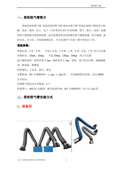
一、柔性吸气臂简介
系统用柔性吸气臂|设备用柔性吸气臂|壁挂式吸气臂|管道安装吸气臂适用于机械、食品、制药、化工、电子、汽车等各行业产生的焊烟、废气、粉尘、油雾、油烟等废气物的源头排放的收集,是目前最高效灵活的烟尘废气捕集装置。
轻巧便捷,旋转灵活。
全方位、多角度准确定位,可自由悬停于任意三维空间进行工作。
规格参数:
常规长度:2米、3米。
可选1.5米、2.5米、4米、5米、6米、7米其它可定做常规管径:150mm、160mm。
可选200mm、250mm、300mm 其它可定做
进口钢丝软管:软管厚度0.3mm 钢丝直径1.2mm 材料:进口复合纤维,耐酸碱腐蚀,耐高温,耐磨损
软管颜色:工业灰、蓝色、黑色
内置骨架:304不锈钢材料(1.1mm、1.2mm厚),引进德国阻尼结构,活动30000次不松动。
常规吸气臂活动关节数量:3个
常规罩口:喇叭形/礼帽型,配风量调节阀。
304不锈钢材料(实卡0.7mm厚)。
二、柔性吸气臂安装方式
1、设备用
2、壁挂式
3、管道式。
新版全国焊接烟尘净化器工商企业公司商家名录名单联系方式大全179家
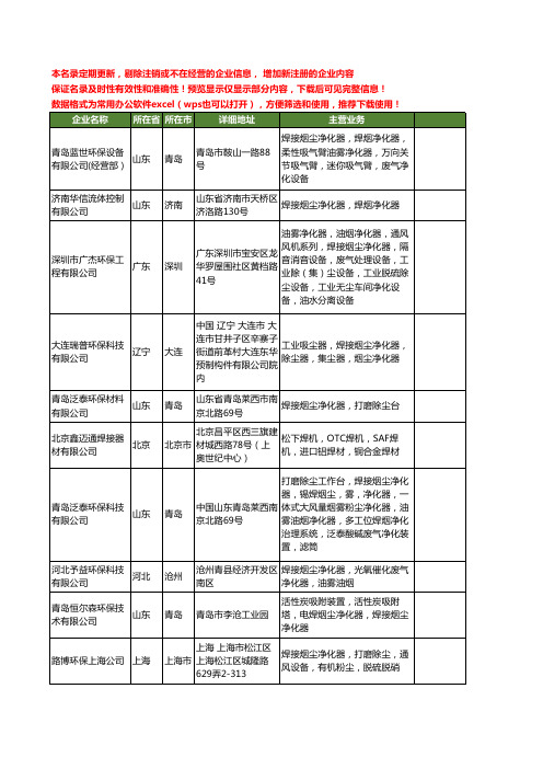
保证名录及时性有效性和准确性!预览显示仅显示部分内容,下载后可见完整信息!
数据格式为常用办公软件excel(wps也可以打开),方便筛选和使用,推荐下载使用!
企业名称
所在省 所在市
详细地址
主营业务
青岛蓝世环保设备 有限公司(经营部)
北京市
北京市石景山区古城 西街21号院C座古城 基地
器,工业粉尘净化器,油雾收集 净化器,切削液油水分离机,工 业除臭废气净化器,UV光解除 味净化器,通风管道,风机消音
器,风管进出风口消音器
深圳市广杰环保工 程有限公司
广东
深圳
工业油烟雾净化回收器,工业焊
深圳宝安区龙华镇大 浪街道浪口工业区一 号
接烟尘净化器,工业无尘车间净 化器,工业隔音消音器,工业除 尘器,工业废气处理器,餐饮油 烟净化器,工业脱硫除尘器,通
北京金科环保设备 有限公司
北京
青岛舜天泽焊烟净 化设备厂
山东
鲁青岛路博环保有 限公司
山东
北京市
北京 北京市石景山 区 古城西街33号
油水分离机,油烟净化器,油雾 收集器,除味,除恶臭设备
青岛
山东省·青岛市·青岛 焊接烟尘净化器,电焊烟雾净化
市开发区井冈山路 器,打磨除尘工作台,万向吸气
658号
臂,关节内置式吸气臂,焊烟机
上海
深圳市广杰环保工 程有限公司
广东
青岛路博伟业环保 科技有限公司
山东
青岛
移动电焊烟尘净化器,焊接烟尘 青岛市区李沧工业园 净化器,移动焊接烟尘除尘器,
烟尘净化设备,吸气臂
青岛
山东省·青岛市·山东 省青岛市李沧区李沧 工业园16号
一种外挂式动臂塔吊支撑装置[实用新型专利]
![一种外挂式动臂塔吊支撑装置[实用新型专利]](https://img.taocdn.com/s3/m/c4b9182cb6360b4c2e3f5727a5e9856a561226d1.png)
(19)中华人民共和国国家知识产权局(12)实用新型专利(10)授权公告号 (45)授权公告日 (21)申请号 201922323030.7(22)申请日 2019.12.23(73)专利权人 中建八局第一建设有限公司地址 250100 山东省济南市历下区工业南路89号(72)发明人 祁延飞 赵忠杨 孔亮 邵飞翔 霍文涛 魏书圣 乔元亮 陈前钟 刘昊 薛龙 时春彬 刘轩 樊春保 曹文静 刘刚 张童 张汝超 迟靖宜 (74)专利代理机构 济南信达专利事务所有限公司 37100代理人 孙晶伟(51)Int.Cl.B66C 23/78(2006.01)(54)实用新型名称一种外挂式动臂塔吊支撑装置(57)摘要本实用新型公开了一种外挂式动臂塔吊支撑装置,属于建筑施工领域;所述的装置包括支撑主梁、底座机构、水平支撑机构和竖向斜撑机构;两个支撑主梁的顶面安装一对可纵向调节的底座机构,每个支撑主梁的外侧分别安装水平支撑机构,每个支撑主梁的底面分别安装竖向斜撑机构;支撑主梁和水平支撑机构配合,实现动臂吊塔纵向维度的稳定支撑;支撑主梁和竖向斜撑机构配合,实现动臂吊塔竖向维度的稳定支撑;支撑主梁和可纵向调节的底座机构配合,实现对外挂式动臂吊塔水平维度的调节,从而实现调节动臂塔吊与核心筒结构之间距离的目的;本新型装置结构简单,便于安装、节省工时,同时对动臂塔吊调节的灵活性较高,便于工作人员的施工操作。
权利要求书1页 说明书3页 附图2页CN 211419401 U 2020.09.04C N 211419401U1.一种外挂式动臂塔吊支撑装置,其特征是所述的装置包括支撑主梁、底座机构、水平支撑机构和竖向斜撑机构;两个支撑主梁的顶面安装一对可纵向调节的底座机构,每个支撑主梁的外侧分别安装水平支撑机构,每个支撑主梁的底面分别安装竖向斜撑机构。
2.根据权利要求1所述的外挂式动臂塔吊支撑装置,其特征是所述底座机构包括C型框底座和活动安装机构;支撑主梁的顶面分别开设数个均匀分布的固定孔,C型框底座分别通过活动安装机构与对应的固定孔连接。
拓能空调空气吸引器泡沫吸引器套装Bdu510b250vm4P590204-1安装手册说明书
Read these instructions carefully before installation. Keep this manual in a handy place for future reference.The original documentation is written in English. All other languages are translations.CONTENTS1. COMPONENTS12. PREPARATION FOR INSTALLATION13. INSTALLATION PROCEDURE24. DRAINAGE PIPE INSTALLATION45. ELECTRICAL WIRING46. TRIAL OPERATION PROCEDURE57. CHECK AFTER INSTALLATION78. MAINTENANCE 71. COMPONENTS Check that the following accessories are provided and that each accessory is correct in amount.PRECAUTIONThe accessories are required for the installation of the air conditioner. Be sure to keep them until the installation work is Drain Pump assembly Hanging bracket Drain connecting pipe 1Drain connecting pipe 2Drain connecting pipe 3Shape Quantity12111NameHeat insulating tube 1Heat insulating tube 2Heat insulating tube 3Heat insulating tube 4Heat insulating material 1Shape ID38 x L35ID38 x L125ID38 x L114ID38 x L9460 x 290Quantity11113NameHeat insulating material 2Heat insulating material 3Heat insulating material 4Mounting screw Hose bandShape 20 x 400230 x 25090 x 240M5x12Quantity21183NameCable tie 1Cable tie 2Plastic band Installation manual Shape L265L150Quantity 11112. PREPARATION FOR INSTALLATION 2.1 Required Installation SpaceTo install an indoor unit with the drain pump kit, a clearance of 560mm or more is required between the ceiling slab and the ceiling surface (Refer to figure below). Provide an inspection hatch in a position where you can readily service the indoor unit and the drain pump kit.Side Viewlower than the bottom surface of the indoor unit2.2 Drain Pump Kit InstallationBe sure to install this drain pump kit after installing the indoor unit to the ceiling.Failure to follow this instruction may result in damage to the drain pump kit.Note: The bottom surface of the drain pump kit will be lower than the bottom surface of the indoor unit.If this drain pump kit must be installed before the indoor unit is installed to the ceiling, place the indoor unit on wood timbers etc.After installing the drain pump kit, install the indoor unit carefully. Do not push, pull or apply excessive force to drain pump kit, it may damageand cause water leakage.CAUTIONTo ensure the proper installation of the drain pump kit, please take note the following consideration when installing the indoor unit.• Be sure that the suction side or drain socket side of the indoor unit is not at higher side of unit. Otherwise, the fl oat switch maymalfunction, causing water leakage or other failure.Suction Side(Indoor unit)Drain Socket3. INSTALLATION PROCEDURECAUTION• Do not hold the drain pump kit by the drain socket when installing it to the indoor unit. Doing so may apply excessive force to the rootof the socket, resulting in water leakage.• Do not give an excessive load up and down, when pulling and inserting the drain plug.• Be sure to turn OFF the power to the indoor unit before starting the procedure below.1. Assemble two hanging brackets (included) to the drain pump kit using mounting screw (included).2. Pre-tighten mounting screw (included) at four prepared holes at unit side panel.3. Mount the drain pump kit to the four pre-tightened screws at unit side panel, then tighten all the screws to fix the drain pump kit to side panel.4. Insert heat insulating tube 1 (included) onto indoor unit drain socket.5. Wrap the threaded end of the drain connecting pipe 1 (included) with thread seal tape. Then attach the drain connecting pipe 1 to the indoor unitdrain socket.6.Insert heat insulating tube 2 (included) onto drain connecting pipe 1.7. Insulate drain connecting pipe 2 (included) with heat insulating tube 3 (included), heat insulating tube 4 (included) and heat insulating material 1.Note: Be sure to apply glue around the join of heat insulating tube 3 and heat insulating tube 4.8. After glue dry, affix heat insulating material 1 (included) to cover the join area.Apply glue around the Heat insulating material 1 9. Connect the drain connecting pipe 2 to the drain pump kit and the drain connecting pipe 1.Note: Be sure to connect the elbow side of the drain connecting pipe 2 to the drain pump kit.10. Clamp the pipe joints with the hose bands (included).11. Wrap heat insulating material 2 around the drain connecting pipes at hose band location. Then wrap the drain connecting pipes with heatinsulating materials 3 and heat insulating material 4. And finally wrap the exposed heat insulating tube with heat insulating material 1.12. Connect the drain connecting pipe 3 (included) to the outlet of the drain pump kit.Note: Be sure to incline the external drain pipe downward.13. Clamp the pipe joints with the hose bands (included).14. Do not install the heat insulating material (fi eld supply) to the outlet of the drain pump kit at this point. It will be installed after the draining checkin the trial operation procedure (Refer to 6. TRIAL OPERATION PROCEDURE).4. DRAINAGE PIPE INSTALLATIONInstall the drain pipe to ensure proper drainage.1. Use a pipe diameter equal to or larger than that of the connecting pipe (PVC pipes with a nominal diameter of 25mm and an external diameter of 32mm).2. Make the pipe length as short as possible and incline the pipe downward at a ratio of 1/100 or greater to prevent the accumulation of air.3. Install pipe supports at intervals of 1.0m to 1.5m to prevent defl ection.4. Use a new drain hose and hose bands when replacing the drain pump kit with a new one.CAUTION• The height of the drain-up pipe must be 750mm or less relative to the indoor unit drain outlet.• The rising drain-up pipe must be installed vertically.• Refer to the fi gure below for concentrated drain piping.750m mo rl e ss5. ELECTRICAL WIRINGPerform electrical wiring for the drain pump kit properly as follows.CAUTION• Be sure to turn OFF the power to the indoor unit before starting the procedure below.1. Remove the indoor unit control box cover.2. Insert drain pump and fl oat switch lead wires through the rubber bush on the hanging bracket. Route and connect the lead wires to the printed circuit board of the indoor unit (Refer fi gure below).3. Bind the lead wires together with the drain connecting pipe 1 (included) using cable tie 1 (included).Note: Do not compress the insulation after install the cable tie. Be sure the lead wire is fi xed close to the indoor unit.4. Clamp the lead wires inside control box using cable tie 2 (included) and plastic band (included), along the path to PCB, secure with other hardness wires fi xing band (Refer to fi gure below).5. Remove the short circuit connector from the X15A terminal on the indoor unit printed circuit board (A1P).6. Connect the fl oat switch lead wire to the X15A terminal.7. Connect the drain pump lead wire to the X25A terminal.8. After completion of the wiring, be sure to organize the wires neatly, bind together and clamp the wires.9. Install back the indoor unit control box cover.DRAIN PUMP LEAD WIREX25A X15A INDOOR UNIT PRINT MPCIRCUIT BOARD INDOOR UNITDRAIN PUMP ASSYSWITCHFLOAT LEAD WIREFLOAT SWITCH6. TRIAL OPERATION PROCEDURECAUTION• Be sure to turn OFF the power to the indoor unit before starting the procedure below.1. Check again that the installation and electrical wiring procedures for the drain pump kit have been completed properly.2. Remove the inspection port cover from the drain pump kit and service panel from the Indoor unit (Refer to figure below).3. To check the drain condition of the drain pump kit, pour approximately 3 litres of water from the service panel opening into drain pan(Refer to fi gure below).4. Ensure that the water fl ows out smoothly without leakage.■IF ELECTRICAL WIRING HAS BEEN COMPLETED:5. After making sure that the indoor unit control box cover is closed, turn ON the power.6. Use the remote controller to perform COOL operation and check the drain condition by pressing upward the drain connecting pipe 3 (included).NOTE:• If using a VAV type air conditioner, you may not be able to perform COOL operation unless trial operation of the outdoor unit is completed.In this case, check the drain condition by performing COOL operation during or after trial operation of the outdoor unit.7. After checking the drain condition, stop the COOL operation and reinstall the service panel and the inspection port cover.■IF ELECTRICAL WIRING HAS NOT BEEN COMPLETED:5. Remove the indoor unit control box cover, connect the remote controller to P1 and P2 terminal of the operation terminal block (X2M).Connect a single-phase 220V~240V power supply and earth wire to the L, N and earth terminal of the power terminal block (X1M).Then close the indoor unit control box cover and turn ON the power.6. Use the remote controller to start trial operation mode and select FAN operation mode with the operation mode button.7. Press the ON/OFF button to start the drain pump. Press upward the drain connecting pipe 3 (included) to check the drain condition(Refer to fi gure below).CAUTION• Be careful as pressing the ON/OFF button causes the indoor unit fan to rotate.8. After completion of the drain condition check, turn OFF the power. Then disconnect the remote control wire and the earth wire, and close thecontrol box cover.Reinstall the service panel and the inspection port cover.9.1. Reinsert the drain connecting pipe 3 (included) all the way and clamp it with a hose band (included).Note: Be sure that there is no gap between the drain connecting pipe 3 (included) and the drain pump kit.2. Insulate the drain connecting pipe 3 (included) with insulation tube (fi eld supply) to prevent dew condensation.7. CHECK AFTER INSTALLATIONCheck again at the least the following items after completion of installation.Check Item Check MarkAre the indoor unit and the drain pump kit installed horizontally?Is the drain pipe connected fi rmly?Is there no possibility of water leakage?Is the drain piping properly inclined downward (1/50 to 1/100)?Is the drain hose adequately insulated?Are the wires connected correctly?8. MAINTENANCEClean the drain pump kit at the end of every season in which the unit is used for cooling.1. Drain all the water out of the drain pump kit by removing the insulation plug and rubber plug.Note: Even after removing the rubber plug from the drain pump kit, some water may remain trapped in the drain connecting pipes and the drain pump kit.2. Remove the inspection port cover from the drain pump kit.3. Remove dust and water in the areas around the inspection port.4P590204-1 2019.07C o p y r i g h t 2019 D a i k i n。
焊烟万向吸气臂
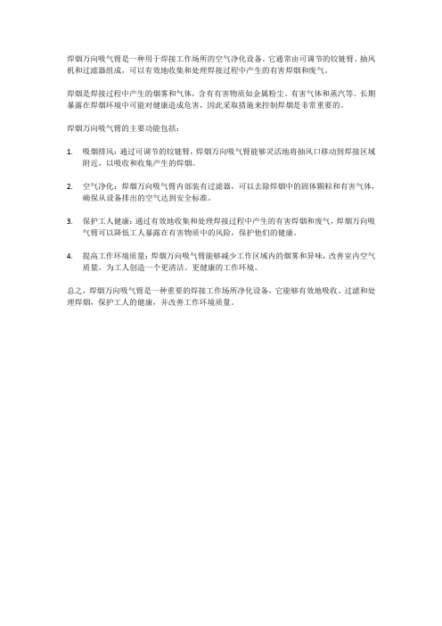
焊烟万向吸气臂是一种用于焊接工作场所的空气净化设备。
它通常由可调节的铰链臂、抽风机和过滤器组成,可以有效地收集和处理焊接过程中产生的有害焊烟和废气。
焊烟是焊接过程中产生的烟雾和气体,含有有害物质如金属粉尘、有害气体和蒸汽等。
长期暴露在焊烟环境中可能对健康造成危害,因此采取措施来控制焊烟是非常重要的。
焊烟万向吸气臂的主要功能包括:
1.吸烟排风:通过可调节的铰链臂,焊烟万向吸气臂能够灵活地将抽风口移动到焊接区域
附近,以吸收和收集产生的焊烟。
2.空气净化:焊烟万向吸气臂内部装有过滤器,可以去除焊烟中的固体颗粒和有害气体,
确保从设备排出的空气达到安全标准。
3.保护工人健康:通过有效地收集和处理焊接过程中产生的有害焊烟和废气,焊烟万向吸
气臂可以降低工人暴露在有害物质中的风险,保护他们的健康。
4.提高工作环境质量:焊烟万向吸气臂能够减少工作区域内的烟雾和异味,改善室内空气
质量,为工人创造一个更清洁、更健康的工作环境。
总之,焊烟万向吸气臂是一种重要的焊接工作场所净化设备,它能够有效地吸收、过滤和处理焊烟,保护工人的健康,并改善工作环境质量。
一种无潜水员动态柔性立管防弯器连接的方法
图 2 动态柔性立管防弯器截面示意图 软管端头 防弯卡子
防弯器连接 法兰
防弯器
图 3 动态柔性立管防弯器结构示意图
图 4 动态柔性立管防弯器结构示意图
取液压拉伸的方式来进行法兰连接处的螺栓紧固。完成后, 潜水员解除软管上索具,防弯器的连接完成。
总的来说,现今海上作业仍然是以传统连接方式为主。 但在项目的实际应用中,发现这种使用潜水员的连接方式上 有一系列的限制条件。
当动态柔性软管下放到一定深度后,FPSO 绞车释放钢 丝绳,使用 ROV(水下操作机器人)来辅助连接钢丝绳和软 管端头。直至软管到达 FPSO 单点底部,预留在单点底部的 索具将动态软管临时悬挂在单点底部,如图 4 所示,此时进 入防弯器连接阶段。当 FPSO 单点底部做连接时,往往根据 作业水深来决定采用空气潜水或饱和潜水的方式来辅助防 弯器的海底连接。潜水员到达作业区域后,使用浮袋或倒链 先卸掉防弯卡子,通过倒链将防弯器与护管口对齐,然后采
工程技术
2023 NO.5(下) 中国新技术新产品
一种无潜水员动态柔性立管防弯器
连接的方法
张 杨1 邱建斌1 王 贺1 陈 帅1 位 强2
(1. 深圳海洋工程技术服务有限公司,广东 深圳 518000 ;2. 海洋石油工程股份有限公司,天津 300452)
摘 要 :动态柔性立管是连接海底与海上生产设施重要的装备之一,而防弯器作为其连接中的重要一环,主要功
液压缸 阳极
观察窗
图 5 无潜水员防弯器母头
凸轮环
弹簧锁 指示
DBSC母 头弹簧锁
ROV插拔 接口
ROV 把手处
4 结论
总的来说,从操作层面上来看,无潜水员操作的防弯器 连接无论是在防弯器的连接和解脱,作业空间,作业水深, 和对作业环境的要求等方面都有显著的优势。从经济成本的 角度来看,更少的连接作业时间将大大推进项目进程,节约 人员成本。从安全性上考虑,无潜水员的方式避免了潜水员 在海底可能产生一系列潜在风险。
45尺伸缩摇臂操作方法
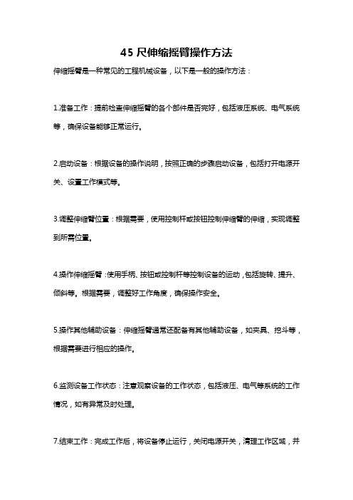
45尺伸缩摇臂操作方法
伸缩摇臂是一种常见的工程机械设备,以下是一般的操作方法:
1.准备工作:提前检查伸缩摇臂的各个部件是否完好,包括液压系统、电气系统等,确保设备能够正常运行。
2.启动设备:根据设备的操作说明,按照正确的步骤启动设备,包括打开电源开关、设置工作模式等。
3.调整伸缩臂位置:根据需要,使用控制杆或按钮控制伸缩臂的伸缩,实现调整到所需位置。
4.操作伸缩摇臂:使用手柄、按钮或控制杆等控制设备的运动,包括旋转、提升、倾斜等。
根据需要,调整好工作角度,确保操作安全。
5.操作其他辅助设备:伸缩摇臂通常还配备有其他辅助设备,如夹具、挖斗等,根据需要进行相应的操作。
6.监测设备工作状态:注意观察设备的工作状态,包括液压、电气等系统的工作情况,如有异常及时处理。
7.结束工作:完成工作后,将设备停止运行,关闭电源开关,清理工作区域,并
将设备归位。
重要提示:以上仅为一般的操作方法,具体操作还需根据设备的型号和操作手册来进行,且操作人员需具备相关的培训和资质。
在操作过程中,要格外注意安全,遵循设备相关的使用规定。
【CN209665314U】一种倒挂直线滑台六自由度平台结构【专利】
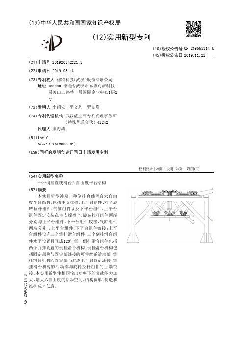
(19)中华人民共和国国家知识产权局(12)实用新型专利(10)授权公告号 (45)授权公告日 (21)申请号 201920342221.5(22)申请日 2019.03.18(73)专利权人 穆特科技(武汉)股份有限公司地址 430000 湖北省武汉市东湖高新科技园关山二路特一号国际企业中心1层2号(72)发明人 李绍安 罗文豹 罗良峰 (74)专利代理机构 武汉蓝宝石专利代理事务所(特殊普通合伙) 42242代理人 廉海涛(51)Int.Cl.B25H 1/10(2006.01)(ESM)同样的发明创造已同日申请发明专利(54)实用新型名称一种倒挂直线滑台六自由度平台结构(57)摘要本实用新型涉及一种倒挂直线滑台六自由度平台结构,包括主支撑架、上平台组件、六个旋转拉杆组件、气缸组件以及下平台组件,上平台组件固定安装在主支撑架上,旋转拉杆组件两端分别与上平台组件、下平台组件铰接,气缸组件两端分别与上平台组件、下平台组件铰接;上平台组件设有三个倒挂滑台组件,三个倒挂滑台组件水平设置且互成120°;每一倒挂滑台组件包括两个并排设置的倒挂滑台机构,倒挂滑台机构包括固定部和与固定部连接的可伸缩的活动部,倒挂滑台机构的固定部与所述上平台固定连接,倒挂滑台机构的活动部与旋转拉杆组件的上端铰接。
本实用新型使相同输出功率下的负载能力加大,增大六自由度的活动空间,结构简单、制造和维护成本低廉。
权利要求书2页 说明书4页 附图4页CN 209665314 U 2019.11.22C N 209665314U权 利 要 求 书1/2页CN 209665314 U1.一种倒挂直线滑台六自由度平台结构,基于stewart平台,其特征在于,包括一个主支撑架(1)、上平台组件、六个旋转拉杆组件(5)、气缸组件(6)以及一个下平台组件,所述上平台组件固定安装在所述主支撑架(1)上,所述旋转拉杆组件(5)上端与所述上平台组件铰接,所述旋转拉杆组件(5)下端与所述下平台组件铰接;所述气缸组件(6)一端与所述上平台组件铰接,另一端与所述下平台组件铰接;所述上平台组件包括上平台(2)及三个倒挂滑台组件,所述三个倒挂滑台组件互成120°且水平设置在所述上平台(2)上,所述上平台(2)设有通孔,所述通孔形状与所述倒挂滑台组件配合;每一所述倒挂滑台组件包括两个并排设置的倒挂滑台机构(4),所述倒挂滑台机构(4)包括一固定部和一与所述固定部连接的可伸缩的活动部,所述倒挂滑台机构的固定部与所述上平台(2)固定连接,所述倒挂滑台机构(4)的活动部与所述旋转拉杆组件(5)的上端铰接。
发动机呼吸器[实用新型专利]
![发动机呼吸器[实用新型专利]](https://img.taocdn.com/s3/m/718634db3968011ca20091a4.png)
专利名称:发动机呼吸器
专利类型:实用新型专利
发明人:王利,张强
申请号:CN200920028052.4申请日:20090617
公开号:CN201539292U
公开日:
20100804
专利内容由知识产权出版社提供
摘要:一种发动机呼吸器,包括呼吸器体、过滤芯、折流板、上盖、密封垫,其特征在于所述折流板垂直地安装于吸器体入口内,过滤芯安装于吸器体内腔,其上下端安装有密封垫,上盖安装于呼吸器体上端。
本实用新型具有平衡曲轴箱内外压力、过滤曲轴箱挥发出的油蒸气、达到减少有蒸汽排放和提高机器周围空气质量的特点,广泛在12V190发动机和类似设备上应用。
申请人:胜利油田胜利动力机械集团有限公司
地址:257032 山东省东营市北一路101号
国籍:CN
代理机构:东营双桥专利代理有限责任公司
代理人:李夫寿
更多信息请下载全文后查看。
竹节万向吸气臂的作用
竹节万向吸气臂的作用竹节万向吸气臂是一种具有很强吸附力和灵活性的机械臂,其作用主要是用于工业生产线上的吸取和搬运工作。
它的设计灵感来自于竹子的节理结构,能够实现多方位的吸附和运动。
竹节万向吸气臂的主要作用是提高生产效率和工作安全性。
它可以灵活地吸附和搬运各种形状和大小的物体,无论是平面的还是立体的,都能够轻松应对。
这大大减轻了工人的劳动强度,提高了工作效率。
同时,它的吸附力非常强大,可以牢固地吸附物体,避免在搬运过程中物体掉落或滑动,减少了事故的发生。
竹节万向吸气臂具有多个关节,每个关节都可以自由旋转和伸缩,使得它能够实现多方位的运动。
这使得它可以轻松地在狭小的空间中操作,并且可以到达一些人难以达到的位置。
不仅如此,它还可以通过调节关节的角度和长度,使吸附头达到最佳的吸附效果。
竹节万向吸气臂采用了先进的吸气技术,通过吸气杯将物体牢固地吸附在其吸附头上。
吸附头上的吸气杯表面有很多小孔,当吸气泵产生负压时,空气会被抽出吸气杯内部,从而形成真空吸附。
这种吸附方式不仅可以吸附平面物体,还可以吸附一些较为凹凸不平的物体。
竹节万向吸气臂的控制系统非常智能化,通过使用传感器和计算机控制,可以实现自动化的吸附和搬运操作。
它可以根据物体的大小、重量和形状自动调整吸附力和搬运速度,保证吸附的稳定性和安全性。
同时,它还可以通过编程设置各种工作模式,实现不同的吸附和搬运任务。
竹节万向吸气臂的应用领域非常广泛。
它可以应用于电子、汽车、食品、医药等各个行业的生产线上,用于吸取和搬运各种零部件、产品和原材料。
它还可以应用于仓储物流领域,用于搬运和堆垛货物。
此外,它还可以应用于危险环境或无法人工进入的场所,用于搬运和清理。
竹节万向吸气臂作为一种具有强吸附力和灵活性的机械臂,可以在工业生产线上实现多方位的吸附和搬运工作。
它的作用主要是提高生产效率和工作安全性,减轻工人的劳动强度,同时还可以应用于各个领域的生产和物流工作中。
随着科技的不断进步,竹节万向吸气臂的应用前景将更加广阔。
竹节万向吸气臂的作用
竹节万向吸气臂的作用竹节万向吸气臂是一种常用于工业生产线的机械装备,它具有多种功能和作用。
本文将从多个方面介绍竹节万向吸气臂的作用。
竹节万向吸气臂可以用于吸尘和除尘。
在工业生产过程中,常常会产生大量的粉尘和污染物,如果不及时清理,不仅会影响工作环境,还会对工人的健康造成危害。
竹节万向吸气臂可以通过强力风机将粉尘吸入,然后通过过滤设备将粉尘分离出来,从而达到清洁空气的目的。
这种吸尘装置具有灵活性强、吸力大、过滤效果好等特点,能够满足不同工作环境的需求。
竹节万向吸气臂还可以用于物料输送和处理。
在工业生产中,常常需要将物料从一个地方输送到另一个地方,竹节万向吸气臂可以通过吸力将物料吸入管道中,并通过管道输送到指定位置。
这种输送方式具有快捷、高效、灵活等特点,可以大大提高生产效率。
竹节万向吸气臂还可以用于工件夹持和定位。
在加工生产中,常常需要夹持工件以保证加工精度和稳定性,竹节万向吸气臂可以通过吸盘或夹具夹持工件,实现工件的固定和定位。
这种夹持方式不仅具有可靠性高、操作方便等优点,还可以适应不同形状和尺寸的工件。
除此之外,竹节万向吸气臂还可以用于工作台的支撑和调节。
在工业生产中,为了保证工作的稳定性和舒适性,常常需要将工作台调整到适合的高度和角度。
竹节万向吸气臂可以通过其灵活的连接方式和可调节的结构,实现工作台的支撑和调节,使工人在工作时更加方便和舒适。
竹节万向吸气臂还可以用于机器人和自动化生产线。
随着科技的发展,越来越多的工业生产开始引入机器人和自动化装备。
竹节万向吸气臂可以与机器人和自动化设备相结合,实现更加高效和智能的生产方式。
机器人可以通过控制竹节万向吸气臂的伸缩和转动,实现自动化生产线的操作和处理。
竹节万向吸气臂具有吸尘和除尘、物料输送和处理、工件夹持和定位、工作台支撑和调节、机器人和自动化生产线等多种作用。
它在工业生产中起到了关键的作用,提高了生产效率和质量,改善了工作环境和条件。
随着科技的不断发展,竹节万向吸气臂将会在更多领域得到应用和推广。
- 1、下载文档前请自行甄别文档内容的完整性,平台不提供额外的编辑、内容补充、找答案等附加服务。
- 2、"仅部分预览"的文档,不可在线预览部分如存在完整性等问题,可反馈申请退款(可完整预览的文档不适用该条件!)。
- 3、如文档侵犯您的权益,请联系客服反馈,我们会尽快为您处理(人工客服工作时间:9:00-18:30)。
.
壁挂式柔性吸气臂
设备名称: LB-JYB壁挂安装式柔性吸气臂
连接方式:固定托架连接(由弹性胶圈密封)
罩口形式:锥型吸口(A)、马蹄型吸口(L)、板式吸口(T)、礼帽型吸(H)其它形式罩口可订制。
罩口配风量调节阀.
设备长度: 2m、3m、4m(4m以上需配备延长托臂,长度可达10m)。
设备管径: φ150mm、φ175mm、φ200mm(其他规格需定制)。
外管材料: 进口PVC钢丝风管,抗腐蚀,耐温1400C。
骨架材料:除弹簧为弹簧钢镀锌外,其它金属构件及紧固件均为
304#不锈钢。
路博LB-JYB柔性吸气臂外皮采用耐酸碱耐140摄氏度高温进口PVC软管,内部构件及罩口托架均采用不锈钢材料,可360度任意悬停,带吸口风量调节阀。
其良好的拉伸悬停特性不但能与各类型焊接烟雾净化器和除尘机配套使用,也可直接安装在墙壁或系统上配合管路用于烟尘气体的排放。
全不锈钢罩口内壁及支架,永不生锈.抗腐蚀,耐酸碱盐,耐高温,质量轻,强度高,带助力装置,操作省力,悬停自如.吸气臂广泛应用于金属加工、焊接烟尘、工件打磨、热加工油雾处理、异味清除、粉尘清除等行业。
可选配件:罩口防火网;工作射灯;光、烟、温感探头。
路博可以根据用户不同的需求定制各种符合你工况的吸气臂系列产品。