基于USB5534B的四个端口USB3.0HUB设计
USB集线器与供电解决方案

10
VariSense Technology™
4种可编程设置,用于调节USB PHY接收器的灵敏度,从而应对严重的 信号损失
基本USB PHY仅有系统架构
全功能系统架构 ,不采用
VariSense FAILS EL_17
全功能系统架构,采用
VariSense PASSES EL_17
注:值仅用于举例说明。实际值可能有变化。
Microchip ESS 14025
© 2014 Microchip Technology Incorporated.
3
集线器 —— 核心技术
链路电源管理 (LPM)
不采用LPM 采用LPM
传统USB信号传输
即便没有要发送的数据,传统USB规范仍 会要求每1 ms查询一次,即USB主机查询 USB设备,使得总线始终处于活动状态 。 即使没有事件发生,也消耗了功率
拥塞点—— 单个TT瓶颈
SIE
Hub Repeater
TT
TT
TT
.... .... ....
TT
Routing Logic
Downstream PHY #1
Downstream PHY #2
Downstream PHY # N
Downstream PHY #1
Downstream PHY #2
To FS Peripheral
6
MultiTRAK™
Microchip USB2.0集线器*
采用MultiTRAK
To HS Host
To HS Host
其他USB 2.0集线器
MultiTRAK
Upstream PHY SIE
Speed Key: 480 Mbps Path 12 Mbps Path
ORICO奥睿科4口USB3.0高速HUBM3H4评测 一款非常出色的桌面型USB3.0 HUB

ORICO 奥睿科4 口USB3.0 高速HUBM3H4 评测一款非常出色的桌面型USB3.0 HUB
ORICO(奥睿科)是大家所熟知的IT 及电源周边厂商,其存储相关和HUB 等产品有着较高的市场占有率。
此次与大家分享的是一款ORICO 4 口USB3.0 高速HUB M3H4。
一、开箱
一如往常,很ORICO 的包装,全环保纸材。
信息标注在背面。
这是一款USB3.0 4 口HUB,也就是USB3.1 Gen1,理论最高传输速率可达5Gbps,为目前市面上最常见的主流HUB,当然ORICO 也已经推出了支持最新USB3.1 Gen2 的HUB 产品M3H4 G2,理论最高传输速度翻倍,可达10Gbps。
内部通过瓦楞纸巧妙隔离并起到缓冲保护作用。
ORICO 奥睿科4 口USB3.0 高速HUB M3H4 主体为铝镁合金,表面氧化着色,有亮银、深灰、粉银三种颜色,数据线为A-A USB3.0 线缆。
铝镁合金带来很好的金属质感,四个横向排开的USB 接口间距宽裕;整。
基于USB5534B的四个端口USB3.0HUB设计

线, 可 支 持 双 向并 发 全 双 工 数 据 传 输 , 这 就 是 Us B3 . 0 传输 速率 猛增 的关键 原 因。 此 外, US B 3 . O R取 了新 的 电源 管 理机 制 , 支 持 待机、 休眠和暂停等状态 , 还 可 为 外 设 提 供 高达 9 0 0 mA的 电力 支持 。 US B 3 . 0 性 能 不 仅
4 3 7 1 0 0 )
摘 要: 集 线器是 u s B系统金 字塔型拓 扑结构 中不可或 缺 的组 成部分 。 本文首 先介  ̄U S B 3 . 0  ̄H U B 的特 点 , 然 后详细论 述基 于U S B 5 5 3 4 B
的 四 个 端 口US B 3 . 0 H UB  ̄计 , 最 后探 讨 U S B 3. o k 口E S D 保 护设 计, 验 证 结 果 表 明 该 设 计 的 可 行 性 以及 未 来 应 用前 景 。 关键词 : U S B 3 . 0 集线嚣 U S B5 5 3 4 B E S D 保 护 中图分 类号 : T N 4 0 3 文献标识码 : A 文章 编号 : 1 6 7 2 — 3 7 9 1 ( 2 0 1 4 ) 0 5 ( a ) 一 0 0 0 4 — 0 2
图1 US B 3. 0 A型插 头示意 图
US B 3 . 0 使 用一组 独立 的总线 连接 至US B 3 . 0 心 则单 独 设计 。 这种 U S B 3 . 0 HUB 的 设计 方
下 层4 个 触 点 中 的 D+和 D一丽 个 触 点 为 控 制 中心 , 而 US B 2 . 0 及 以 下标 准 的 控 制 中 式 可 避 免US B3 . O 设 备 在 进 行 超 高 速 数 据 研 发成本 很低 低
基于CYUSB3014 USB3.0总线开发技术
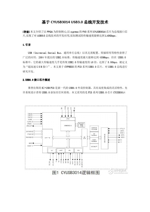
基于CYUSB3014 USB3.0总线开发技术[导读]本文介绍了以FPGA为控制核心,以cypress的FX3系列CYUSB3014芯片为总线接口芯片,实现了对USB3.0总线技术的开发应用,实际测试的传输速度能够达到1.43Gbps。
1.引言USB(Universal Serial Bus,通用串行总线)以其无需配置、即插即用等特性获得了广泛的应用。
2004年提出的USB2.0标准,传输速度最大能够达到480Mbps。
但在 USB3.0标准中,它的最大传输速度几乎是传统USB2.0传输速度的10倍,达到了5.0Gbps,被定义为“超高速U S B接口”。
本文基于CYPRESS的FX3系列USB3.0芯片,对USB3.0总线进行研究开发。
B3.0接口芯片概述赛普拉斯的EZ-USB FX3是新一代的USB3.0外设控制器,具有高度集成的灵活特性,允许系统设计者将USB3.0添加至任何系统。
本文采用的是FX3系列USB3.0芯片CYUSB3014FX3是完全兼容USB3.0 V1.0和USB2.0规范的,集成的USB2.0 OTG控制器允许芯片作为主从设备使用。
另外,它还支持一些常用的外设接口,如SPI,I2C,UART和I2S可以与外部设备进行通信。
FX3具有一个可进行完全配置的并行通用可编程接口GPIF II,它可以与任何处理器、ASIC或是FPGA连接。
它可以轻松无缝地连接至多种常用接口,比如异步SRAM、异步和同步地址数据复用式接口、并行 ATA等等。
EZ-USB FX3集成了USB3.0和USB2.0物理层(PHY)以及32位ARM926EJ-S微处理器,具有强大的数据处理能力,并可用于构建定制应用。
3.系统整体设计本系统设计主要由软件部分和硬件部分组成。
软件部分主要包括三大部分:PC机应用程序、FX3固件程序FPGA程序。
硬件部分主要由FPGA、USB3.0芯片和DDR2组成,硬件的系统框图如图2所示。
USB 3 扩展器 4-端口点对点扩展器系统用户手册说明书
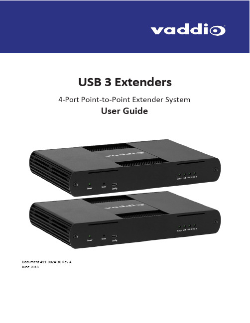
USB 3 Extenders4-Port Point-to-Point Extender SystemUser Guide Array Document 411-0024-30 Rev AJune 2018ContentsIntroduction (3)Features (3)Unpacking (3)A Quick Look at the USB 3 Extenders (4)The Local (Rx) Extender (4)The Remote (Tx) Extender (5)Installation (6)Preparing Your Site (6)Cabling Guidelines (6)Other Items You Will Need (6)Basic Connections (7)Optional Ethernet Pass-Through Connection (7)Connections for a Presenter BYOD Scenario (8)Installing the Extenders (8)Checking the Installation (8)Connecting a USB Device (9)Compatibility (9)Troubleshooting (9)Specifications (12)Technical Glossary (13)Contacting Technical Support (13)Compliance Statements and Declarations of Conformity (14)FCC Radio Frequency Interference Statement Warning (14)CE Statement (14)IC Statement (14)WEEE Statement (14)Product Operation and Storage (14)IntroductionThis guide provides product information, installation instructions and troubleshooting guidelines for Vaddio USB 3 Extenders. The instructions in this guide assume a general knowledge of computer installation procedures, familiarity with cabling requirements and some understanding of USB devices.FeaturesThis product enables you to extend USB 3.1 beyond the standard 3m cable limit for USB 3.1 peripheral devices. This product also supports USB 3.0, 2.0, and 1.1. This extender system is composed of two individual units, the Local Extender and the Remote Extender, and has the following key features:▪Support for new USB 3.1 host controllers and devices (up to 5 Gbps)▪Transparent USB extension supporting USB 3.1, 3.0, 2.0, and 1.1▪Up to 328 ft (100 m) of extension when directly connected over Cat-6/Cat-7 cable▪True plug and play; no software drivers required▪Works with all major operating systems: Windows®, macOS™, Linux® and Chrome OS™ Unpacking999-1005-032 – North America999-1005-132 – Europe and UKYour USB 3 Extender system contains:▪Local (Rx) extender▪Remote (Tx) extender▪USB 3.0 cable, 6 ft (1.8 m)▪Local extender 24V DC 1A power adapter with AC cord set(s)▪Remote extender 24V DC 2.71A power adapter with AC cord set(s)▪Quick-Start GuideA Quick Look at the USB 3 ExtendersThe local (receiver) and remote (transmitter) extenders look similar, but are not interchangeable. They use different power supplies as well. Please take the time to identify each part correctly.The Local (Rx) ExtenderThe local (receiver) extender connects to the computer using a standard USB 3.1 cable. Power for this unit is provided by the included 24V 1A adapter.Front ViewRear ViewITEM TYPE DESCRIPTION1 Power LED ON when DC is supplied to the extender unit. OFF when no power is supplied bythe AC Adapter.2 Mode Reserved for manufacturer use.3 Config Reserved for manufacturer use.4 Status LED ON when system is functioning normally. BLINKS when system is booting. BLINKS inunison with the LINK, USB 2, and USB 3 LEDs to indicate a temperature warning.5 Link LED ON when Local Extender is linked to an opposite Remote Extender. OFF whenthere is no connection between the Local and Remote Extenders.6 USB 2 LED ON when an active USB 2 connection is established through the extender system.BLINKS when the USB 2 connection is suspended/asleep. OFF when no USB 2connection is detected.7 USB 3 LED ON when an active USB 3 connection is established through the extender system.BLINKS when the USB 3 connection is suspended/asleep. OFF when no USB 3connection is detected.Ethernet pass through channel connects to a network or Ethernet device.8 LAN Port (100/1000Mbps)9 Link Port (RJ45) Accepts RJ45 connector for Cat-6/Cat-7 cabling to connect the Local Extender tothe Remote Extender.10 USB Host Port USB 3 Type B receptacle used to connect Local Extender to USB 3 Host computer.11 DC Power Port Locking connector for the included power adapter – accepts 24VDC 1A.The Remote (Tx) ExtenderThe remote (transmitter) extender provides USB 3.1 Type A ports for standard USB devices and allows you to connect up to four USB devices directly. The remote extender is powered by an external AC 24V 2.71A adapter, supplying up to 1.2 Amp per USB port. Additional devices may be connected by attaching up to three USB hubs to the remote extender.Front ViewRear ViewITEM TYPE DESCRIPTION1 Power LED ON when DC is supplied to the extender unit. OFF when no power is supplied by theAC Adapter.2 Mode Reserved for manufacturer use.3 Config Reserved for manufacturer use.4 Status LED ON when system is functioning normally. BLINKS when system is booting. BLINKS inunison with the LINK, USB 2, and USB 3 LEDs to indicate a temperature warning.5 Link LED ON when Remote Extender is linked to an opposite Local Extender. OFF when thereis no connection between the Local and Remote Extenders.6 USB 2 LED ON when an active USB 2 connection is established through the extender system.BLINKS when the USB 2 connection is suspended/asleep. OFF when no USB 2connection is detected.7 USB 3 LED ON when an active USB 3 connection is established through the extender system.BLINKS when the USB 3 connection is suspended/asleep. OFF when no USB 3connection is detected.8 LAN Port (100/1000Ethernet pass through channel connects to a network or Ethernet device.Mbps)9 Link Port (RJ45) Accepts RJ45 connector for Cat-6/Cat-7 cabling to connect the Remote Extender tothe Local Extender.10 Device Ports (Type A) Accepts all USB devices.11 DC Power Port Locking connector for the included power adapter – accepts 24VDC 2.71A.InstallationPreparing Your SiteBefore installing Vaddio USB 3 Extenders, you will need to prepare your site:1.Place the equipment where desired and set it up.2.Be sure your USB devices are within 328 ft (100 m) of the computer. If not, adjust the location of yourdevice(s) and/or computer accordingly.Cabling GuidelinesUse foiled (FTP) or shielded (STP) cabling if the cable run installation has any of these characteristics: ▪The cable is bundled with other cables▪The cable is run tight against other Category cables▪The cable is placed near sources of interference like power lines and radios▪The cable is looped or coiledThe maximum installation distance is 328 ft (100 m). This includes the length of any patch cables. Upto 33 ft (10 m) of patch cable can be used.For best performance, use shielded or foiled Cat-6/Cat-7 cable.When terminating cables, ensure the matching RJ45 connector is used for the cable type. Forexample, if Cat-6a cable is used, then Cat-6a compatible RJ45 connectors must be used.Otherwise, the benefits of using higher grade cabling may not be realized.When installing, ensure the cable is installed away from, or isolated from potential sources ofinterference such as electrical wiring, fluorescent lighting, etc.Other Items You Will NeedTo complete the installation, you will also require the following items that are not included with this system: ▪USB compatible computer (host computer) with a USB compliant operating system▪USB compatible device(s)▪Cat-6/Cat-7 unshielded twisted pair (UTP) cable and RJ45 connectors, ensuring the total cable length (including patch cables, if any) does not exceed 328 ft (100 m).Basic ConnectionsIn this scenario, USB and network connectivity extend to a camera installed some distance away.Optional Ethernet Pass-Through ConnectionThe USB 3 Extenders offer a 100/1000 Mbps Ethernet pass through connection that can be used for: ▪Connecting network devices▪Extending network access to the same location as the Remote Extender▪Leveraging existing cabling to provide USB connectivity without losing network connectivityOn one of the extenders, connect the LAN port to the network. On the other extender, connect the LAN port to the network port on a device requiring network connectivity.CAUTION: DO NOT CONNECT BOTH EXTENDERS TO THE NETWORK.Connections for a Presenter BYOD ScenarioIn this scenario, the presenter needs to run a soft conferencing application. The laptop’s USB is extended to the AV Bridge MatrixMIX elsewhere in the auditorium, with cameras (and possibly audio equipment) connected to it. The AV operator controls the video source for the conference. The presenter’s laptop is the local (Rx end) device, but the closest network connection is closer to the Remote (transmit) end equipment.Installing the ExtendersThe two extenders use different power supplies. Use the correct power supply for each extender.Using the wrong power supply on either extender could damage the system and void your warranty.1.Place the local (Rx) extender near the computer and use its 24V, 1A power supply to connect it to power.2.Connect the local extender’s Host port to a USB 3 port on the computer using the supplied USB3.1 cable.3.Place the remote (Tx) extender near the USB device.4.Connect the Link port on the local (Rx) extender to the Link port on the remote (Tx) extender using a Cat-6/Cat-7 cable.Do not exceed 33 ft (10 m) total of patch cable when using premise cabling.5.Connect the 24V, 2.71A power supply to the remote (Tx) extender and to power.Checking the Installation1.On both extenders, check that the Power, Status, Link, USB 2 and USB 3 LEDs are on. If the Link LEDs are off,check the cabling between the extenders. Correct the problem before continuing.2.Windows: On the connected computer, open Device Manager. Expand the entry for Universal Serial Buscontrollers by clicking the “+” sign. If the extenders are installed correctly, two instances of “GenericSuperSpeed USB Hub” are listed.Windows 7: Open the Start Menu, right click Computer, select Manage >> Device Manager.Windows 8, 8.1 or 10: Right click the Start Menu; select: Device Manager.3.MacOS: On the connected computer, o pen the System Profiler. In the left-hand column under Hardware,select “USB”. If the extender has been installed correctly, two separate instances of “Hub” are listed under the USB SuperSpeed Bus.To open System Profiler: Open the Finder, select Applications, then open the Utilities folderand double click on the System Profiler icon.4.If the extender system is not detected correctly or fails to detect, consult the T roubleshooting section.Connecting a USB Device1.If necessary, install any software required to operate the USB device. Refer to the documentation for theUSB device, as required.2.Connect the USB device to a USB device port on the Remote Extender.3.Check that the device is detected and installed properly in the operating system. CompatibilityThe USB 3 Extenders comply with USB 2.0 and USB 3.1 Gen 1 specifications governing the design of USB devices and suppo rt USB 3.1, 3.0, 2.0, and 1.1. Ho wever, there is no guarantee that all USB devices or hosts will be compatible as several factors affect the operation of USB devices over extended distances. TroubleshootingIf you are unable to resolve an issue after following these instructions, please contact Technical Support for further assistance.SpecificationsRANGEPoint-to-Point Up to 100m (328 ft) over CAT6a/7 CableUSB DEVICE SUPPORTMaximum Throughput 5 GbpsTraffic Types All Traffic TypesDevice Types All Device TypesMaximum Number of Devices and/or Hubs Up to 30 devicesLOCAL EXTENDERUSB Connector 1 x USB 3.1 Gen 1 Type B ReceptacleLink Connector 1 x RJ45 “LINK”Network Pass Through: 1 x RJ45 “LAN”Dimensions137.3mm x 232.1mm x 33.0mm (5.4” x 9.1” x 1.3”) Enclosure Material Black Anodized AluminumPower Supply100-240V AC Input, 24V 1A DC OutputREMOTE EXTENDERUSB Connector 4 x USB 3.1 Gen 1 Type A ReceptaclesLink Connector 1 x RJ45 “LINK”Network Pass Through: 1 x RJ45 “LAN”Dimensions137.3mm x 232.1mm x 33.0mm (5.4” x 9.1” x 1.3”) Enclosure Material Black Anodized AluminumAvailable Current Up to 1.2 Amp (6W) to each USB portPower Supply100-240V AC Input, 24V 2.71A DC OutputENVIRONMENTALOperating Temperature Range0°C – 50°C (32°F – 122°F)Storage Temperature Range-20°C – 70°C (-4°F – 158°F)Operating Humidity20% to 80% relative humidity, non-condensing Storage Humidity10% to 90% relative humidity, non-condensing COMPLIANCEEMC FCC (Class B), CE (Class B)Environmental RoHS2 (CE)Technical GlossaryCat-6a/Cat-7 Network Cabling –also called Category 6a/Category 7. T his cabling is available in either solid or stranded twisted pair copper wire variants and as UTP (unshielded t wisted pair), F TP (foiled t wisted pair) or STP (shielded twisted pair). UTP cables are not surrounded by any shielding making them more susceptible to electromagnetic interference (EMI). FTP/STP cables include shielding the copper wires and provide better protection against EMI.USB 3 and USB 2.0 Cables – have two distinct full-sized connectors. The Type A connector is used to connect the cable from a USB device to the Type A port on a computer or hub. The Type B connector is used to attach the USB cable to a USB device.RJ45 – the Registered Jack (RJ) physical interface connects the network cabling (Cat-6a/Cat-7) to the local (Rx) and remote (Tx) extenders. You may use either the T568A scheme (Table 1) or the T568B scheme (Table 2) for cable termination. The USB 3 Extenders require all four pairs of the cable. Note that any give cable must be terminated using the same T568 scheme on both ends to operate correctly.RJ45 Pin-OutsContacting Technical SupportIf you are experiencing problems not referenced in the Troubleshooting section, or require further assistance, contact Vaddio Technical Support.Compliance Statements and Declarations of ConformityFCC Radio Frequency Interference Statement WarningThis device complies with Part 15 of the FCC rules. Operation is subject to the following two conditions:(1) This device may not cause harmful interference, and (2) this device must accept any interference received including interference that may cause undesired operation.CE StatementThe original manufacturer declares that this product is in conformity with European Standards EN 55022, EN 55024, EN 55032 and EN 61000.IC StatementThis Class B digital apparatus complies with Canadian ICES-003 Issue 6.WEEE StatementThe European Union has established regulations for the collection and recycling of all waste electrical and electronic equipment (WEEE). Implementation of WEEE regulations may vary slightly by individual EU member states. Please check with your local and state government guidelines for safe disposal and recycling or contact your national WEEE recycling agency for more i nformation.Product Operation and StoragePlease read and follow all instructions provided with this product, and operate for intended use only.Do not attempt to open the product casing as this may cause damage and will void warranty. Use only the power supply provided with this product (if applicable). When not in use, product should be stored in a dry location between -20°C and 70°C.Vaddio is a brand of Milestone AV Technologies · Phone800.572.2011/+1.763.971.4400·Fax+1.763.971.4464·********************Visit us at for firmware updates, specifications, drawings, manuals, technical support information, and more. Vaddio is a trademark or registered trademark of Milestone AV Technologies. All other brand names or marks are used for identification purposes and are trademarks of their respective owners.In British Columbia, Milestone AV Technologies ULC carries on business as MAVT Milestone AV Technologies ULC.。
usb3.0 hub方案
USB3.0 Hub方案概述USB(Universal Serial Bus,通用串行总线)是一种用于在计算机系统之间传输数据和供电的通用接口标准。
USB接口得到了广泛应用,如连接打印机、键盘、鼠标、摄像头、存储设备等。
随着需求的增加,USB集线器(Hub)变得不可或缺。
本文将介绍一种USB3.0集线器方案,以满足高速数据传输需求。
USB3.0技术概述USB3.0是USB接口的升级版本,提供更高的数据传输速度和更高的功率输出。
相对于USB2.0,USB3.0的主要改进有: - 更高的传输速度:USB3.0的传输速度最高可达到5 Gbit/s,比USB2.0的480 Mbit/s要快10倍。
- 增加带宽:USB3.0使用双向数据传输,在USB2.0的基础上新增了四条数据线,分别用于接收和发送数据。
- 更强大的供电能力:USB3.0接口提供更高的功率输出,最高可达到4.5 W。
USB3.0 Hub方案设计为了实现高速数据传输,USB3.0集线器需要具备以下关键特性: 1. 快速传输速度:支持USB3.0的5 Gbit/s传输速度。
2. 多口输出:提供多个USB接口,方便用户同时连接多个USB设备。
3. 适配器供电:为连接的USB设备提供稳定的电力。
4. 多系统兼容性:兼容与USB2.0和USB1.1设备的连接,并自动适配传输速度。
USB3.0集线器芯片选择选择一款适合的USB3.0集线器芯片对方案的成功至关重要。
以下是一些常见的USB3.0集线器芯片供参考: - 瑞萨电子(Renesas)的µPD720210:该芯片集成了USB3.0 Hub控制器和USB接口电路,支持4个USB3.0端口和电源管理功能。
- VIA Technologies的VL812:该芯片支持7个USB3.0端口,提供72 Mhz的内部晶振,并通过FIFO(先进先出)架构来提供高传输速度。
- Genesys Logic的GL3520:该芯片支持4个USB3.0端口,并具备多种保护功能,如过流保护、超过温度保护等。
USB3.0 spec
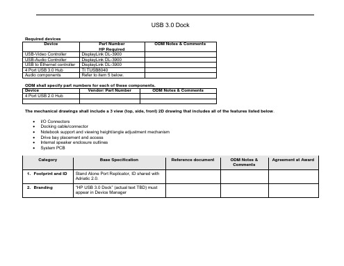
Vendor/ Part Number
ODM Notes & Comments
4 Port USB 2.0 Hub
The mechanical drawings shall include a 3 view (top, side, front) 2D drawing that includes all of the features listed below.
usb3.0 spec usb3.0 dock required devices device part number hp required odm notes commentsusb-video controller displaylink dl-3900 usb-audio controller displaylink dl-3900 usb ethernetcontroller displaylink dl-3900 portusb 3.0 hub ti tusb8040 audio components refer below.odm shall specify part numbers components.device vendor/ part number odm notes portusb 2.0 hub mechanicaldrawings shall include view(top, side, front) 2d drawing includesall featureslisted below. dockingcable/connector notebooksupport viewingheight/angle adjustment mechanism drivebay placement internalspeaker enclosure outlines systempcb category base specification reference document odm notes commentsagreement idstand alone port replicator, id shared adriatic2.0. branding"hp usb 3.0 dock" (actual text tbd) must appear devicemanager category base specification reference document odm notes commentsagreement portexpander module). usb2.0 ports usb3.0 ports from internal hub. total current shared among usb ports should 2.5amps continuous current.
USB3.0硬件设计指南
Cap Value 0.1 uF, 0.01 uF 0.1 uF, 2.2 uF 0.1 uF, 2.2 uF 0.1 uF, 2.2 uF 0.1 uF, 0.01 uF 0.1 uF, 0.01 uF Number of caps 4 of each 1 of each 1 of each 1 of each 1 of each 1 of each per supply Pin Name VDD AVDD U3TXVDDQ U3RXVDDQ CVDDQ VIO1-5
This protection ensures the device will continue to function after ESD events up to the levels stated. The SSRX+, SSRX-, SSTX+, SSTX- pins have only up to +/- 2.2KV Human Body Model (HBM) internal ESD protection. Additional protection can be added to these pins by using high performance, low capacitance external ESD devices. To prevent an effect on the performance of this bus, the added capacitance should not exceed 0.4 pF. In terms of EMI, all signal and clock traces emit electromagnetic (EM) radiation when they switch from one level to another. To meet the various standards in different countries, these emissions must be minimized. You can use several techniques to lower EM emissions:
usbhub方案

usbhub方案USB HUB方案随着科技的不断发展,各类数码设备越来越多,我们的电脑所需要的USB接口也越来越不够用了。
为了解决这个问题,USB HUB方案应运而生。
USB HUB是一种扩展USB接口的设备,它可以将一个USB接口扩展为多个,并且能够同时连接多个USB设备。
本文将介绍USB HUB的原理和应用领域。
一、USB HUB的原理USB HUB是通过内部集线器实现的。
当USB HUB接收到主机发送的请求时,它会自动切换到集线器模式。
集线器模式下,USB HUB会将接收到的数据重新发送到所有连接的USB设备中,同时还会为每个USB设备分配一个地址。
这样,每个USB设备就可以独立地与主机进行通信,而不会干扰其他设备的正常工作。
二、USB HUB的应用领域1. 个人电脑在个人电脑上,由于各类外设的普及,我们经常会遇到USB接口不够用的情况。
比如,我们需要连接鼠标、键盘、音响、打印机等多个设备,但是电脑上只有两个USB接口。
这时,我们可以通过USB HUB将电脑上的USB接口扩展为多个,从而满足连接多个设备的需求。
2. 商务办公在商务办公场景中,人们经常需要使用投影仪、摄像头、音响等设备。
而这些设备通常都是通过USB接口与电脑相连。
如果电脑上的USB接口不够用,就无法同时使用这些设备。
而通过使用USB HUB,我们可以方便地将电脑上的USB接口扩展为多个,从而满足商务办公的需求。
3. 游戏娱乐在游戏娱乐领域,许多游戏控制器、游戏盘等设备都是通过USB 接口与电脑或游戏主机相连的。
而随着游戏设备的增多,我们常常会遇到USB接口不够用的情况。
通过使用USB HUB,我们可以轻松地将电脑或游戏主机上的USB接口扩展为多个,从而满足连接多个游戏设备的需求。
4. 移动办公在移动办公中,我们经常需要连接移动硬盘、U盘、手机等设备。
但是,许多笔记本电脑只有一个或两个USB接口。
通过使用USB HUB,我们可以将笔记本电脑上的USB接口扩展为多个,从而方便地连接多个移动设备。
hub供电改造
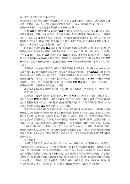
锦上添花--给你的USB HUB补充动力笔者所用的笔记本电脑只有一个USB接口,当使用USB鼠标时,闪存盘、DC及其他USB 设备只能呆在一边。
为了给笔记本电脑扩展工作能力,本人到电脑城花20元购买了一个一转四的USB接口,也就是通常所说的USB Hub(如图1)。
熟悉USB接口特性的朋友都知道,USB接口可以采用极连的方式扩展至100余个接口,因此采用这种一转四的接口在理论上肯定毫无问题。
但在实际使用过程中并非如此,同时使用闪存、鼠标等USB设备时均无任何问题,但当使用数码相机时费了很大“劲儿”才在“我的电脑”中出现“可移动磁盘”的盘符,而外接打印机工作时,在打印过程中频频出错。
很明显,USB供电不足这一常见故障“光临”了。
网上有人建议将USB Hub的四个接口并联后增加输出功率以解决供电不足的问题,从简单的物理电学考虑也知道这是不现实的想法。
USB Hub上四个接口的电源均来自主板同一个USB接口,而这个USB接口只提供500mA的电流。
在不增加电压的情况下,怎么可能会出现4×500mA=2000mA的情况呢?据我所知,电脑城中有专门提供外接电源的USB Hub出售,但是价格比较昂贵。
是否能给自己的Hub添加个外接电源呢?本人的手又“痒”了起来。
将所购的USB Hub拆开后在电路板上发现有两处空焊的地方,其中标注为J4的地方为三孔(如图2),由其布线的情况来看,很像是电器上的电源接口,而USB Hub的面板上竟然也有与此相对应的插孔。
翻转过来,仔细观察线路板,发现三孔的走线正好与USB接口的电源线相连。
很明显厂商利用同一条生产线生产了两种型号的USB Hub,一种为带外接电源的,一种是不带外接电源的。
看来,我可以对此USB Hub进行一下改造,给其加上一根外接电源线,以便弥补其供电能力的不足。
改造所需工具:废旧随身听变压器一个,7805稳压集成块一个(如图3),电烙铁一把。
给变压器稳压众所周知,随身听变压器提供的电源为6V,而USB接口只需5V电源。
和芯润德USB3.0 HUB芯片 SL6340 简要说明书
深圳市和芯润德科技有限公司USB3.2 Gen1X1 4口集线器芯片SL6340简要数据手册V1.1 2023.09.25USB3.2 Gen1X1接口4口集线器控制器集成电路概述SL6340是一款USB3.2 Gen1X1接口的4口HUB控制器芯片,片上集成32位微处理器,它具有低功耗、高性能、可配置等特点;芯片集成USB3.0高速物理层收发器和USB2.0高速物理层收发器,使得芯片可以完美支持超高速、高速和低速USB上下行设备连接;芯片集成度高,内部集成5V转3.3V和5V转1.1V DCDC,极大的精简了外围电路。
SL6340支持符合USB IF规范的BC1.2快充协议,他可以为苹果、三星设备提供最高1.5A的充电电流。
SL6340支持通过外挂SPI-flash/EEPROM配置设备信息,本版本SL6340芯片必须配置SPI-FLASH使用,我司提供配置程序/或完成程序配置的SPI-FLASH。
功能特点●SL6340符合USB3.2 V1.0 规范。
◆SL6340向下兼容支持USB2.0、USB1.1规范◆SL6340上行口支持超高速SS、高速HS、低速FS设备◆SL6340下行口支持超高速SS、高速HS、全速FS、低速LS设备◆SL6340S支持一路控制和一路中断●SL6340集线器芯片上行口USB和下行口USB端口都支持BC1.2快充协议◆支持BC1.2快充协议、支持SDP(Standard Downstream Port), CDP,DCP, and ACA-Dock◆SL6340支持数据传输同时为移动设备充电(BC1.2)◆SL6340下行口USB可以从标准的USB口切换为快充口或者专用充电端口◆SL6340上游非标准USB HOST/OTG,依然可以支持BC1.2快充协议,此时需要电源适配器行供电.●SL6340集成USB3.2 Gen1X1 超高速收发器,集成USB2.0高速收发器●SL6340下行端口设备支持过流保护,支持USB2.0挂起和恢复。
电脑显示器上增加4个USB3.0接口,简单好用!
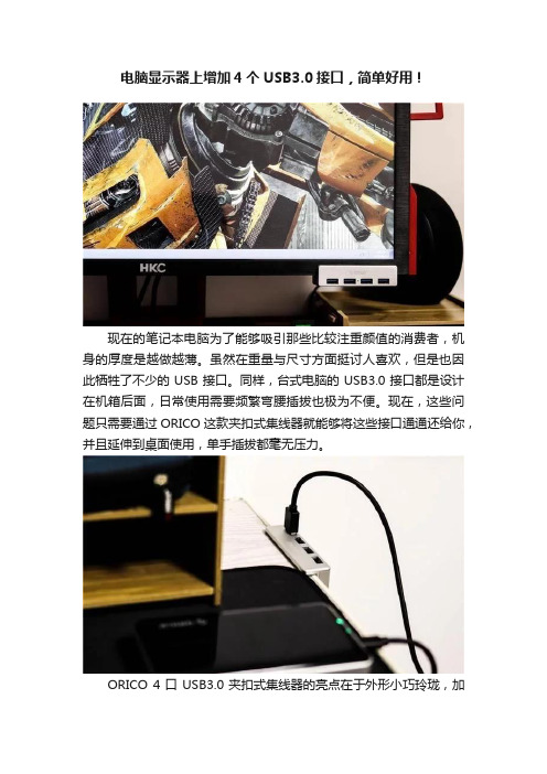
电脑显示器上增加4个USB3.0接口,简单好用!现在的笔记本电脑为了能够吸引那些比较注重颜值的消费者,机身的厚度是越做越薄。
虽然在重量与尺寸方面挺讨人喜欢,但是也因此牺牲了不少的USB接口。
同样,台式电脑的USB3.0接口都是设计在机箱后面,日常使用需要频繁弯腰插拔也极为不便。
现在,这些问题只需要通过ORICO这款夹扣式集线器就能够将这些接口通通还给你,并且延伸到桌面使用,单手插拔都毫无压力。
ORICO 4口USB3.0夹扣式集线器的亮点在于外形小巧玲珑,加之配以卡扣式固定方式,可以固定在显示器、桌沿等处,可有效节省桌面空间;只需占用电脑上的一个高速接口,即可再扩展出四个USB3.0接口,能够如同电脑原生接口一样的速度;安装简单方便,能够在不同的平面上固定,释放双手,单手即可随意插拔USB外设。
包装上秉承ORICO家族式的一贯风格,可降解纸盒加彩色标签,依然是正面英文介绍配产品图,背面有关于产品的详细参数及铭牌信息。
虽然仅仅只是一个小小的USB HUB,但也为其投入了保险,使用过程中,如果因产品问题导致用户的损失,可以得到相应的保险赔偿。
配件清单包含有ORICO 4口USB3.0夹扣式集线器1个,1米的USB3.0公对公数据线,使用说明以及感谢卡各一份。
这款集线器标配的数据线1米长,基本上可以满足大部分场景下使用,为保障数据传输的稳定性以及供电能力,线材非常粗壮结实。
在外观上,ORIC这款造型玲珑小巧,外壳采用了铝合金材质,触感十分有质感,金属银色更显档次以及轻薄的机身方便随身携带,非常精致。
整体尺寸为89*46*23mm,也就五分之四的烟盒大小,不包含螺杆部分。
与银色机身的MAC以及小米类的笔记本搭配更显质感有档次。
单手即可完成U盘的插拔,取决于这个大间距的螺杆,最大与最小的开度为32mm-10mm,开以随意安装在触手可及的不同平面位置。
螺杆头与凹槽位置都置有硅胶保护垫,致使被夹物不会轻易被划伤,同时固定的也更加稳固不脱落。
USB 3.0_HDMI 1.4特性与制程分析
USB3.0/ HDMI 1.4 參數與製程分析研討會主題一、HDMI1.4的公頭、母座及線材結構二、HDM11.4高頻量測規範說明三、USB3.0的公頭、母座及線材結構四、USB3.0高頻量測規範說明五、高頻參數意義與加工製程之關係分析HDMI Type A-AHDMI1.4的公頭、母座及線材結構HDMI線材HDMI Type A-DVIHDMI Type C-C HDMI Type A-CHDMI Type A-DHDMI 裸線材剖面示意圖HDMI1.4的公頭、母座及線材結構不帶HEAC應用的線材剖面圖將其中3根電子線改成STP 即為帶HEAC 線材帶HEAC 應用的線材剖面圖訊號線編織鋁箔麥拉電子線HDMI1.4的公頭、母座及線材結構HDMI 接頭腳位表HDMI1.4的公頭、母座及線材結構HDMI 接頭腳位表:HDMI接腳為直通式,不同型接頭接法為同訊號接點相連,如下表為A及C接頭接法Type C---Type C Type C---Type A Type A---Type AHDMI 連接器:Type B 公頭、母座Type C Plug外被HDMI1.4的公頭、母座及線材結構HDMI 連接器:Type C 公頭、母座Pin #1Pin #19外被HDMI 連接器:Type E 公頭、母座Type E Plug外被USB3.0/ HDMI 1.4 參數與製程分析研討會主題一、HDMI1.4的公頭、母座及線材結構二、HDMI1.4高頻量測規範說明三、USB3.0的公頭、母座及線材結構四、USB3.0高頻量測規範說明五、高頻參數與加工製程之關係分析HDMI 高頻量測參數Impedance(Z diff ) 阻抗ØConnector Imp. 接頭阻抗ØCable imp.線材阻抗DELAY 延遲SKEW 延遲差ØINTRA PAIR SKEW 對內延遲差ØINTER PAIR SKEW 對間延遲差Attenuation 衰減Xtalk 串音ØFEXT遠端串音ØNEXT 近端串音TDR 參數NA 參數HDMI線材的四種高頻規格:TMDS 訊號對測試規格(A)/ HEAC 訊號對測試規格(B)/ 車用接繼線TMDS訊號對測試規格(C)/ 車用直通連接線TMDS訊號對測試規(D)HDMI 1.4 高頻量測規範及參數說明TMDS 訊號對測試規格(A):HDMI 1.4 高頻量測規範及參數說明HEAC 訊號對測試規格(B):USB3.0/ HDMI 1.4 參數與製程分析研討會主題一、HDMI1.4的公頭、母座及線材結構二、HDMI1.4高頻量測規範說明三、USB3.0的公頭、母座及線材結構四、USB3.0高頻量測規範說明五、高頻參數與加工製程之關係分析USB 規範的成品線材-USB 3.0 規範的成品線除A-A的特殊線,其餘為標準的xA-xB的結構。
DIGITUS Business USB 3.0 Hub 4-Port 说明书
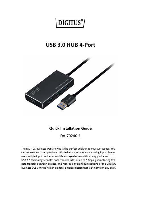
USB 3.0 HUB 4-PortQuick Installation GuideDA-70240-1The DIGITUS Business USB 3.0 Hub is the perfect addition to your workspace. You can connect and use up to four USB devices simultaneously, making it possible to use multiple input devices or mobile storage devices without any problems.USB 3.0 technology enables data transfer rates of up to 5 Gbps, guaranteeing fast data transfer between devices. The high-quality aluminum housing of the DIGITUS Business USB 3.0 Hub has an elegant, timeless design that is at home on any desk.PACKAGE CONTENTS• 4 ports USB 3.0 HUB•One User Manual•With integrated 100cm USB 3.0 cable•One 5V2A adapterFEATURES•Convenient to use - can support 4 ports working at the same time•Portable and easily accessible on your desktop•Supports data transfer rates up to 5Gbps•USB 3.0, USB 1.1 and USB 2.0 compatible•BC1.2 fast charging•LED indicator•Supporting Devices: Mobil phone, keyboard, HDD, Card Reader, USB Fan, mouse, scanner, USB Flash, printer, gamepad, digital camera etc.SYSTEM REQUIREMENTS•PC with Window XP/Vista/7/8/10, Mac9.1 or above•Working Temperature: 0℃~50℃•Storage Temperature: -20℃~60℃INSTALLATIONWindow XP/Vista/7/8/8.1/10, Mac9.1 or above1. Turn your computer on and wait until the system has finished booting2. Connect your computer to USB hub using the enclosed USB cable.3. Connect the USB plug to your computer4. Connect the USB plugs on the peripheral devices (Printer, scanner…etc.)to the USB hub.Hereby Assmann Electronic GmbH, declares that the Declaration of Conformity is part of the shipping content. If the Declaration of Conformity is missing, you can request it by post under the below mentioned manufacturer address.ASSMANN Electronic GmbHAuf dem Schüffel 358513 LüdenscheidGermany。
- 1、下载文档前请自行甄别文档内容的完整性,平台不提供额外的编辑、内容补充、找答案等附加服务。
- 2、"仅部分预览"的文档,不可在线预览部分如存在完整性等问题,可反馈申请退款(可完整预览的文档不适用该条件!)。
- 3、如文档侵犯您的权益,请联系客服反馈,我们会尽快为您处理(人工客服工作时间:9:00-18:30)。
基于USB5534B的四个端口USB3.0HUB设计作者:王东郭阳来源:《科技资讯》2014年第13期摘要:集线器是USB系统金字塔型拓扑结构中不可或缺的组成部分。
本文首先介绍USB3.0及HUB的特点,然后详细论述基于USB5534B的四个端口USB3.0HUB设计,最后探讨USB3.0端口ESD保护设计,验证结果表明该设计的可行性以及未来应用前景。
关键词:USB3.0 集线器 USB5534B ESD保护中图分类号:TN403 文献标识码:A 文章编号:1672-3791(2014)05(a)-0004-02USB全称是通用串行总线(Universal SerialBus),是由英特尔、IBM等多家IT巨头联合提出的接口标准,由于其具有支持热插拔,即插即用,成本低廉等优点,迅速在PC、消费电子产品、工业及军事等诸多领域得到普及。
从1994年USB规范0.7版本问世,到2000年USB2.0版本推出,USB传输速率从1.5 Mb/s跃升到480 Mb/s。
虽然短短几年内USB传输速率得到320倍的提升,但仍无法满足当下以GB为数量级的数据传输需求,因此USB3.0应运而生。
HUB(集线器)是USB系统金字塔型拓扑结构中不可或缺的组成部分,作为一类特殊的USB设备,它建立了主机与USB设备之间的桥梁。
HUB实现USB接口扩展功能的同时,也负责电源管理,总线监测,设备检测和管理等功能,为用户提供高效和友好的使用体验。
1 USB3.0及HUB介绍英特尔、HP、NXP等业界领先公司于2008年底正式发布USB3.0标准,SuperSpeedUSB 理论最高速率达5.0Gbps,USB3.0数字设计采用双总线结构,向下兼容USB2.0以及更低版本。
在接口结构方面,为兼容USB2.0及以下接口标准,USB3.0将接口巧妙的设计为上下两层触点相交错的结构,如图1所示。
下层4个触点中的D+和D-两个触点为USB2.0数据收发差分触点,用来进行高速数据传输,两侧的GND和VBUS为电源触点;上层新增加的5个触点,USB3_TX是超高速数据发送差分触点,USB3_RX是超高速数据接收差分触点,中间GND触点是为连接额外的信号接地线。
相比USB2.0的半双工二线制总线,USB3.0采用对偶单纯形四线制差分信号线,可支持双向并发全双工数据传输,这就是USB3.0传输速率猛增的关键原因。
此外,USB3.0采取了新的电源管理机制,支持待机、休眠和暂停等状态,还可为外设提供高达900 mA的电力支持。
USB3.0性能不仅比USB2.0有大幅提高,在主要竞争对手中也脱颖而出,请参见表1。
USB3.0的创新和优势必将使其获得迅速推广,广泛认可。
USB3.0HUB设计与USB2.0及以下标准的HUB设计是相独立,两者互不干扰;USB3.0使用一组独立的总线连接至USB3.0控制中心,而USB2.0及以下标准的控制中心则单独设计。
这种USB3.0HUB的设计方式可避免USB3.0设备在进行超高速数据传输时的干扰,也能对USB2.0及以下的标准实现良好的兼容。
2 USB3.0HUB电路设计USB5534B是MICROCHIP公司推出的四下行端口超高速USBHUB控制器,其符合USB3.0规范要求,它的主要特点如下。
(1)所有下行端口均支持5 Gbps超高速(SS),480 Mbps高速(HS),12 Mbps全速(FS)和1.5 Mbps低速(LS)的USB传输速度。
(2)支持大多数电池供电设备的充电,符合USB-IF电池充电V1.2规范要求。
(3)具备优化的低功耗、低发热的芯片控制和管理。
(4)可以通过SPIROM、OTPROM或SMBus进行芯片配置。
(5)支持JTAG边界扫描。
(6)支持Windows7,Vista,XP和Linux等操作系统。
2.1 HUB电源设计USBHUB供电方案分为总线供电和自供电两种。
采用总线供电HUB可为所有下行USB 设备提供总计小于900 mA电力支持,对下行设备有严格功耗限制,但其具有简单、便携等优势;而自供电HUB则可满足每个下行USB设备高达900 mA电力需求,但是自供电HUB设计较复杂。
本设计兼顾总线供电和自供电方案,用户可根据实际需要自由选择供电方案。
根据参数手册,USB5534B在同时挂载四个超高速USB设备时最大功耗,此时需要3.3 V 和1.25 V电源电流分别为60 mA和1177 mA。
本设计选用TI公司TPS70302PWP低压差线性稳压器,其双路输出电压可编程,对应最大输出电流为1 A和2 A,输出电压由公式1计算得出:,其中=1.224 V (1)当=3.3V时,=51.1KΩ,=30.1 kΩ。
当=1.25V时,=0.64KΩ,=30.1 kΩ。
HUB电源设计如图2所示,HUB可使用上行总线供电工作,也可使用外置+5 V电源供电。
当HUB使用自供电时,Q1A可自动切断上行USB总线供电,降低主机功耗,防止电流倒灌,确保USB设备得到稳定充足供电。
D2对HUB电路进行过压和过流保护。
2.2 HUB过流保护设计考虑到USB设备的安全,USB3.0规范在11.4.1.1.1条对HUB过流保护提出明确要求。
当所有下行端口总电流超过5.0 A预定值时,过电流保护电路应该消除或减少相应下行端口的功耗。
预定值必须大于所允许的最大端口电流或时延的瞬态电流(例如开机,动态连接或重新配置时),并可以受到过电流保护。
本设计选用Diodes公司AP2176S双通道过流保护芯片,可为两个下行端口提供独立的过流保护,其动作电流1 A,关断延时0.1 ms,符合UL60950-1标准中必须限制短路电流在5 s 内小于8 A的要求。
AP2176S的使能输入ENx引脚和故障开漏输出FLAGx引脚分别连接至USB5534B供电使能输出PWRx引脚和过流监测输入OCSx引脚,电流输出OUTx则连接至USB连接器V+引脚。
当任意端口电流大于1 A时,FLAGx输出低电平至OCSx,经可编程的微秒级延时PWRx输出低电平至ENx,相应端口的电流被关断。
2.3 外围配置电路设计稳定性的振荡源和可靠性的复位电路是硬件电路设计的重点。
本设计中采用漂移低的24 MHz有源晶振,配合π型电源滤波网络作为USB5534B时钟电路。
选用复位阈值电压为3.08 V的MAX809T专用电压监控电路,为USB5534B提供可靠且抗干扰的低电平复位信号。
用户可通过内部寄存器、SPIFLASH或SMBus三种方式配置USB5534B芯片。
当系统上电时,如USB5534B检测不到有效的外置SPIFLASH或SMBus使能,则使用芯片内部寄存器默认配置,此时MICROCHIP公司预设于内部ROM中的VID、PID、DID等描述字在枚举过程中被报告。
对于绝大部分应用默认配置即可满足,本设计为后续可能的专业应用预留SPI配置,用户可通过SPIFLASH配置各端口的功耗管理、复合设备、过流保护延时等参数。
3 USB3.0端口ESD保护根据USB3.0规范6.10.1条,所有信号和电源引脚必须能承受2 kV人体放电模型和500 V 充电设备模型而不损坏。
但实际应用中静电放电电压甚至高达8 kV,静电放电经常会导致潜在损害或灾难性故障,额外的ESD保护成为USB端口生存的必要条件。
在业界获得广泛认可的国际电工委员会在IEC61000-4-2条款定义了,在不同的环境和安装条件中ESD测试水平,并建立了相应的测试程序。
按照IEC61000-4-2条款第4级的要求,超高速USB3.0端口一定要能够承受至少8kV的接触放电。
USB3.0传输速度的上升和通道电容的下降,使得分离器件保护效果很不理想,USB2.0的ESD保护方案也不再适用。
本设计选用美国力特公司SP3012-06UTGTVS阵列,其内部二极管能吸收瞬态电流,泻放电流,利用雪崩二极管来钳制电压电平。
SP3012能够在μDFN14的小体积封装内提供6路±12 kVESD保护,使所有USB3.0数据线处于防护之下。
SP3012二极管对地电容典型值为0.5pF,低于USB3.0要求1pF极限值,最大限度的保持了USB3.0数据完整性。
数据发送信号线串联100nF电容可消除低频干扰,USB外壳经过阻容泄放接地,改善系统的EMI特性。
4 结语本文设计的基于USB5534B的USB3.0 HUB严格实现USB规范中要求的全部功能。
利用ATTODiskBenchmark软件测试USBHUB的传输速度,其读取数据可达到960 Mbit/s,写入速度可达到872 Mbit/s。
由于软硬件、线缆等因素影响,虽然实测传输速度较USB3.0理论最大值5 Gbit/s有一定的差距,但应是USB2.0传输速度6倍以上。
该USB3.0HUB具有体积小巧,安全可靠,成本低廉等优点,且为后续开发预留充分,可应用于计算机、电子消费品和工业等领域。
伴随USB3.0主机和设备的迅速普及,该产品将有很好的市场潜力。
参考文献[1] UniversalSerialBus3.0Specification Revision1.0[Z].[2] USB5534B4-PortSS/HSUSBHUBCon trollerDataSheetREVA[Z].[3] DUAL-OUTPUTLOWDROPOUTVOL TAGEREGULATORSWITHINTEG RATEDSVSFORSPLITVOLT AGESYSTEMSRevisionH[Z].[4] 王宗超,倪凯,等.新一代高速串行接口USB3.0介绍[J].技术论坛,2010(2):32-34.。