DTC2058规格书最新版
德国窑触摸屏t8产品手册

二分厂德国窑触摸屏T800产品手册该手册合用于版本V4.0 软件有关手册1234567一级目录:前序第1章安装2启动3操作4管理5个性化(客户设置) / 自定义6以太网总线通信7现场总线通信8管理功能附录 1技术参数附录 2 ORDERING INFORM ATION定购信息附录 3 ASCⅡ码详尽目录:安全提示产品申明第 1 章:1.1 开箱机械装置电源供给帧单元1.3 电器装置后边板布局和连结器引脚散布主从通信插座插座现场总线连结条形码阅读器信号线:视频窗口52500 输出 / 输入单元联接。
信号线:组态端口视频器连结组态电脑1.3.3.2 2500联接电脑运转 ITOOL1.3.3.3 2500联接电脑经过()运转 ITOOL永远联接电脑运转 SCADA布线图供给电源线 A 沟通电B直流电C熔断器替代D熔断器替代1.4 SWITCHING 通信参数1.5 进入第一步时钟手册自检电池检测继电器/LED检测重置RESET INSTRUMENT 2.启动开启电源并翻开显示开用户端口标准端口显示面板导航键键盘操作显示器翻开主面板信息显示信息输入弹出菜单(面板)系统面板显示程序状态程序菜单进入程序菜单报警报警指示办理报警登岸界面进入界面 2.8.1 获准进入标准方法进入用户 ID 进入2.9 磁盘2.10 成立数据库运转自动成立的数据库数据库成立数据库重命名3.操作3.1 运转程序 3.1.1 运转目前的一个程序从一个点运转一个程序SKIP3.1.4.1 片段传输序列3.2 选定 / 撤消一个程序选定程序3.2.1 撤消3.3 监控程序 3.3.1 监控设备3.3.2PREPLOT 设备3.4 导入数据 3.4.1 文档分类3.4.2 磁盘3.4.3 读取数据步骤3.4.4 管理设备3.5 报警信息反应 3.5.1 报警纪录 3.5.2 报警信息确认3.5.3 在报警记录中增添备注报警历史归档3.5.5 报警概略页面3.6 地区和分组显示 3.6.1 一览表3.6.2 功能模块 3.6.3 显示模式3.7 下载方法下载程序3.7.2 监控方法 3.8 批次4.管理4.1 编写程序 4.1.1 简介 4.1.2 程序编写页面进入4.1.3 变动设定值 4.1.4 变动片段4.1.5 插入删除 SEGMENT4.1.7 更改程序 PROPERTIES4.1.8 更改设定点名称4.2 数据导入分组 4.2.1 登岸初始化4.3 应用管理4.3.2 应用管理者页面 4.3.3 停止应用4.3.4 保留应用数据卸载应用程序4.3.6 加载或加载并运转一个应用程序4.3.7 删除应用程序4.4 进入权限 4.4.1 初次进入 4.4.2 编写密码4.4.3 用户 ID 系统4.5 设置并重置设备 4.5.1 编写通信参数4.5.2 设置启动策略重设时钟4.5.4 改换语言 / 日期格式 4.5.5 成立面板显示4.6 拷贝 4.6.1 进入复制页面 4.6.2 复制应用程序数据4.6.3 复制系统数据复制应用程序和系统数据4.7 文档管理 4.7.1 停止应用程序 4.7.2 文档管理文档复制和删除 4.7.4 从头加载应用程序4.8 方法管理 4.8.1 成立文档 4.8.2 方法编写5自定义5.1 简介 5.1.1 词典 5.1.2 面板导航和数据库命名5.2 系统文档词典5.2.1 文档构造 5.2.2 编写系统文本新的语言版本 5.2.4 词典使用词典自定义面板5.3 错误文本词典 5.3.1 编写错误信息5.3.2 成立新的语言错误文本BUENT TEXT 信息用户文档词典程序言档词典面板导航 5.7.1 面板导航文档数据库命名 5.8.1 功能模块命名报警命名5.10 5.11 写入6.以太网总线6.1 进入以太网总线GATEWAY 6.2 以太网总线DCM7. 现场总线7.1 简介控制单元7.3 COMMENTING7.4 安装7.6 全世7.7 操作界8.管理功能8.1 网络编写TRAIL 8.2 管理进入8.3 组态用户选择过滤参数8.4 用户 ID 权限 8.4.1 鉴别考证8.4.2 名字8.4.4 限期8.4.5 屏幕按键附录 1.技术参数惯例参数通信参数功能模块2.定购信息Ⅱ码(计算机内码)。
扫描特ktronic规格标准及合规性说明书
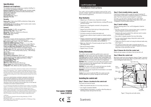
ScantronicSpecificationsStandards and ComplianceThe installer must remove or adjust any compliance labelling if a non-compliant configuration is selected.Intrusion compliance : EN 50131-1:2007+A2:2017; EN 50131-3:2009; EN 50131-6:2017+A1:2021; EN 50131-10:2014; EN 50136-2:2013; BS8243:2010; PD6662:2017Security grade : Grade 2.Environmental class : Class II.Protection: IP40, IK06.SecurityAccess codes : 4-digit, giving 10,000 combinations. 6-digit, giving 1,000,000 combinations.Code blocking : Blocked for 90 secs after 4 incorrect codes in series.Proximity tag differs : 4,294,967,296.GeneralRelative Humidity : 0 to 93%, non-condensing.Operating temp. range : -10°C to +55°C.Dimensions : 239mm (h) x 250mm (w) x 87mm (d).Weight : 2.8kg (without battery).Case material : Steel.ElectricalThis product complies with the requirements of EN50131-6 Type A power supply at Grade 2 and environmental class II.Mains power supply : 230Vac + 10%/-15%, 200mA max, 50Hz.Control unit internal mains fuse : T250mA.Control unit power supply : 13.7Vdc, 1.0A max of which 180mA is reserved for battery recharge and 820mA to power the system.Control unit PCB current consumption : 40mA quiescent; 70mA max (in alarm) excluding external devices and battery charging.Standby battery : 12V, 7Ah, sealed lead acid. Min standby time:12 hrs. (see “Step 2: Check standby battery capacity”). Max recharge time: 72 hrs.12V aux : 600mA max*12V bus : 400mA max*12V to plug-by communicator : 400mA max**Maximum current before triggering over-current protection. Output voltage range : 12V outputs are 9.5Vdc to 13.8Vdc. Max p-to-p ripple voltage : 0.5V.Low-battery fault at : <12V.Aux power output fault at : <9V.OP1-3: Open collector transistor, 500mA max.Plug-by outputs : Open collector transistor, 50mA max.Loudspeaker : 12Vdc, 280mA max. Min impedance 16 Ohm.The information, recommendations, descriptions and safety notations in this document are based on Eaton Corporation’s (“Eaton”) experience and judgment and may not cover all contingencies. If further information is required, an Eaton sales office should be consulted. Sale of the product shown in this literature is subject to the terms and conditions outlined in appropriate Eaton selling policies or other contractual agreement between Eaton and the purchaser.THERE ARE NO UNDERSTANDINGS, AGREEMENTS, WARRANTIES, EXPRESSED OR IMPLIED, INCLUDING WARRANTIES OF FITNESS FOR A PARTICULAR PURPOSE OR MERCHANTABILITY , OTHER THAN THOSE SPECIFICALL Y SET OUT IN ANY EXISTING CONTRACT BETWEEN THE PARTIES. ANY SUCH CONTRACT STATES THE ENTIREOBLIGATION OF EATON. THE CONTENTS OF THIS DOCUMENT SHALL NOT BECOME PART OF OR MODIFY ANY CONTRACT BETWEEN THE PARTIES.In no event will Eaton be responsible to the purchaser or user in contract, in tort (including negligence), strict liability or other-wise for any special, indirect, incidental or consequential damage or loss whatsoever, including but not limited to damage or loss of use of equipment, plant or power system, cost of capital, loss of power, additional expenses in the use of existing power facilities, or claims against the purchaser or user by its customers resulting from the use of the information, recommendations and descriptions contained herein. The information contained in this manual is subject to change without notice.© 2022 EatonEaton, Security House, Vantage Point Business Village, Mitcheldean, GL17 0SZ. Product Support (UK) Tel: +44 (0) 1594 541978 available 08:30 to 17:00 Monday to Friday. email:*****************************Installation InstructionsThe i-on10 is a 10-zone grade-2-compliant control unit. The i-on10 provides a reliable, easy-to-install, wired solution for domestic and small commercial applications.Key features•Supports up to 10 wired zones, all provided on-board.•Compatible with a range of wired detectors, including PIR sensors and door contacts. •Supports up to four keypads connected to the system bus. •Grade 2 compliant.•Support for one full-set level and up to three part-set levels. •Configurable through a keypad.•On-board connections for wired siren/strobe unit.•On-board open-collector output to operate an external auxiliary device. •Plug-by communicator port with 8 outputs to communicate with an alarms-receiving centre (requires MISC-COMPACK12 and a suitable standalone communicator, such as 0840UK-21). •Metal case, fitted with a 1A power supply and space for a 12Vdc 7Ah backup battery. •Back and lid tamper switches. •Support for up to 10 users.Safety InformationThis product must be installed by qualified service personnel. WARNING: BEFORE INSTALLING THIS EQUIPMENT , ENSURE THAT THE MAINS SUPPL Y FOR THE CONTROL UNIT IS DISCONNECTED AND ISOLATED. All electrical connections must be carried out by a qualified electrician and comply with current local regulations.WARNING : When connected to the mains with power applied, mains voltages are present on the shrouded heads of the terminal screws of the mains connector (Figure 4).WARNING: The mains cable to the control unit must use a double-pole isolation device in accordance with EN 62368-1.WARNING: Good practice requires that documentation is not stored within the enclosure.Caution: If you need to handle the PCB in the control unit, take standard precautions to prevent damage by static electricity.Installing the control unitStep 1: Choose a location for the control unitThe control unit must be located:•Within the protected area (but not in an entry or exit zone). •Out of sight of potential intruders.•Upright (battery at the bottom) on a wall or other flat surface (to discourage tamper attempts from the rear).Step 2: Check standby battery capacityCheck that the battery is able to power the system for at least 12 hours during a mains failure, including two periods of 15 minutes in alarm. This is the minimum period for grade 2 compliance.To do this, you will need to calculate the total current drawnfrom the battery during a mains failure. Please refer to the i-on10 Configuration Guide for worked examples.Step 3: Install cablingNote the following (refer to the i-on10 Configuration Guide for guidance):•Normally, standard 7/0.2 un-screened alarm cable is suitable for wiring to keypads and wired siren/strobe units. •Screened cable may be needed if the cable runs near to sources of electromagnetic interference. •Keep cables to keypads separate from any other wiring. •You can connect keypads using a daisy-chain (serial) or star (parallel) configuration. •Cables must enter the control unit using the dedicated cable-entry holes (Figure 1). •The maximum length of the cable to keypads depends on anumber of factors, including the number of keypads and whether daisy-chain or star connections are used.Step 4: Remove the lid of the control unitRelease the two screws on the front of the lid, then lift it off.Step 5: Mount the control unitMount the control unit in the orientation shown in Figure 1 using the three fixing holes and minimum 40mm long No8 (4mm) screws. Use only the designated cable-entry holes.entryMains Signal cable entryFigure 1. Fixing holes and cable entriesPart number 14199588Issue 2 24/01/22Step 6: Position the communicator and fit the fourth pillarIf a communicator is used, position it under the PCB.Fit the supplied fourth pillar for the PCB (see Figure 2), and securethe PCB to the pillar using the supplied M3x12 screw.Figure 2. Fitting the fourth pillarStep 7: Connect all wired devicesConnect all wired devices except the battery, as shown in Figure 3.Step 8: Connect the batteryNote: Connecting the battery does not start the system.Fit a 7Ah lead-acid battery in the bottom-left corner of the control unit.Connect the battery leads to the battery (red to positive and black to negative), and connect the transformer lead to the PCB (Figure 3).Step 9: Connect the mains cableENSURE THAT THE MAINS Y IS DISCONNECTED AND Figure 4. Mains connectionsStep 10: Re-fit the lid, switch on and configure the systemWARNING: During initial power-up, keypad sounders and anyinternal loudspeaker may give an alarm tone. If you are working at the top of a ladder, make sure that the sudden noise does not startle you and cause a fall.Re-fit the lid, then switch on the mains supply to the control unit.Go through the initial configuration prompts and set up the system as described in the i-on10 Configuration Guide . You are prompted to specify installer and user codes during initial system configuration.PCB links and connectorsThe following sections provide information about the links and connectors shown in Figure 3.a Plug-by communicator portYou can connect a plug-by communicator to this port using an optional MISC-COMPACK12 wiring harness (available separately). By default, outputs 1-8 are 0V when active, and 12Vdc when inactive. Please refer to the i-on10 Configuration Guide for the default output type used for each output and programming details.Connect LF (Line Fail) to an output from the communicator that is 12Vdc when communicator detects that there is a communications fault to the ARC, and 0V when no fault is present.If a dual-path (landline and mobile) communicator is used, such as a RedCARE STU, re-program one of the plug-by outputs to type ATS Test, and wire that to the ATS Test input of the communicator. Also connect Line Fail to the Line Fail output of the communicator, asabove. This is needed to comply with BSIA Form No. 175, April 2005. The control unit generates an “ATE LF Single” alert if one network is unavailable, or “ATE LF All” if both are unavailable.Connect RR (Remote Reset) to an output from the communicator that indicates to the control unit that a user can reset the system after a system tamper. The input must be 12Vdc for at least 100ms to indicate the reset, and 0v normally. For further details, see “Remote Reset (Redcare Reset)” in the i-on10 Configuration Guide .Note: During system commissioning, confirm with the ARC that the communicator is working correctly.b System busUp to four keypads can connect to the system bus. The installation instructions supplied with each keypad provide details of how to install the device. The address of each device is set by the control unit, as described in the i-on10 Configuration Guide .Please refer to “Step 3: Install cabling” for guidance about cabling.See also “RS485 bus termination link”.c Loudspeaker connectionsIf fitted, a loudspeaker mimics alarm tones and repeats setting and entry tones. The loudspeaker must be a minimum of 16 Ohms. Note:• A loudspeaker is not a warning device as described by EN50131-4. •You can set the loudspeaker volume from the Installer menu.d Open-collector (wired) outputThe open-collector transistor output can be used to switch external equipment on or off. By default, the output is 12Vdc when inactive and 0V when active (this can be reversed from the Installer menu).e Siren/strobe connectionsPlease refer to the installation instructions provided with the siren/strobe unit for connection details.f Wired zone connectionsYou can connect up to 10 wired detectors (0 to 9) to the control unit using the Fully-Supervised Loop (FSL), 4-wire Closed Circuit (CC) or 2-wire CC wiring method (Figure 5). You must use the same method for all detectors. If 4-wire CC is used, the number of zones is halved and are numbered 1-5. To maintain ten 4-wire CC zones (0-9), fit an ADP -10CC board and configure the resistance setting of each zone as 2k2/4k7.For any method, the total wiring and switch resistance must be lessthan 100 Ohms (EOL resistor shorted in the case of FSL).By default, the system assumes normally-closed contacts. Detectors with normally-open contacts must be programmed with the “Inverted” attribute set.Please refer to the i-on10 Configuration Guide for wiring details ifyou want to use two detectors per zone.Zone 0Zone 14-Wire CC Wiring2-Wire CC Wiring Supported resistor values (± 5%):EOL Alarm2k2 4k7 (default)1k0 1k02k2 2k24k7 4k7FSL Wiring, with 8k2 resistorsFigure 5. Zone wiringg Kick-start linkOrdinarily, the control unit starts only after the mains supply is switched on, even if a battery is connected. If you want to operate the control unit temporarily using only the battery, start the control unit by briefly shorting this link.h Reset codes linkYou can use this link to reset the installer and all user codes (e.g.in the event that codes have been forgotten). All proximity tags are also deleted. This link can be enabled or disabled by a setting in the Installer menu. Please refer to the i-on10 Configuration Guide for further details.i RS485 bus termination linkIf the control unit uses a single daisy chain to connect keypads and is at one end of the chain, fit a jumper across this link in the control unit and in the last keypad on the bus. RS485 termination canimprove performance in electrically noisy environments. The i-on10 Configuration Guide gives further guidance.MaintenanceInspect the control unit once or twice per year as part of general inspection of the whole system. At the control panel, check for any damage, test the battery, and check the action of the tamper switch.Please refer to the i-on10 Configuration Guide for general guidance about maintaining the whole system.Figure 3. Control unit PCBAB+120If a siren/strobe unit is not fitted, connect TR to 0V.d Open-collector outputb Ststem bus(Max 4 keypads)Connect transformer。
蜂巢电子产品指南:第十一月二〇二〇版本B,第二个标准产品提供说明书

Standard Product Offerings* Special order onlyOther products may be available. Refer to individual EW-series’ sheets for full range of solutionsNote: All images herein are generic and may not be representative of actual productElliptical Waveguide and AccessoriesProduct GuideEW17 Series (Special Order Only)Connectors Auxiliary ProductsAccessoriesEW20 Series (Special Order Only)Connectors Auxiliary ProductsAccessoriesEW28 Series (Special Order Only)Connectors Auxiliary ProductsAccessoriesHoistingEW37 SeriesConnectors Auxiliary ProductsAccessoriesEW43 SeriesConnectors Auxiliary ProductsAccessoriesEW52 SeriesConnectors Auxiliary ProductsAccessoriesEW63 SeriesConnectors Auxiliary ProductsAccessoriesHoistingEW64 SeriesConnectors Auxiliary ProductsAccessoriesEW77 SeriesConnectors Auxiliary ProductsAccessoriesEW85 SeriesConnectors Auxiliary ProductsAccessoriesEW90 SeriesConnectors Auxiliary ProductsAccessoriesHoistingEW127A SeriesConnectors Auxiliary ProductsAccessoriesEW132 SeriesConnectors Auxiliary ProductsAccessoriesHoistingEW180 SeriesConnectors Auxiliary ProductsAccessoriesHoistingEW220 SeriesConnectors Auxiliary ProductsAccessoriesHoistingEW240 SeriesConnectors Auxiliary ProductsAccessoriesConnector KitsSplice HardwareGrounding KitsUniversal Grounding Kit 60”UG1215B4-TCompatible with EW63 – EW180Individual specifications can be found in the E-CatalogWaveguide HangersWaveguide Entry EquipmentBoot AssembliesEntrance PanelsElliptical Waveguide - CommScope vs. CompetitorsVisit our website or contact your local CommScope representative for more information.© 2020 CommScope, Inc. All rights reserved.All trademarks identified by ® or ™ are registered trademarks or trademarks, respectively, of CommScope, Inc. This document is for planning purposes only and is not intended to modify or supplement any specifications or warrantie,d in accordance with international standards, including ISO 9001, TL 9000, and ISO 14001.Further information regarding CommScope’s commitment can be found at /About-Us/Corporate-Responsibility-and-Sustainability .CO-114132.1-EN (12/20)CommScope pushes the boundaries ofcommunications technology with game-changing ideas and ground-breaking discoveries that spark profound human achievement. We collaborate with our customers and partners to design, create and build the world’s most advanced networks. It is our passion and commitment to identify the next opportunity and realize a better tomorrow. Discover more at 。
黑金刚
高 信 形状
品
薄 型 化
波 化
命
赖 性
工作上限温度· 标准寿命 (hours)
额定电压范围 (Vdc)
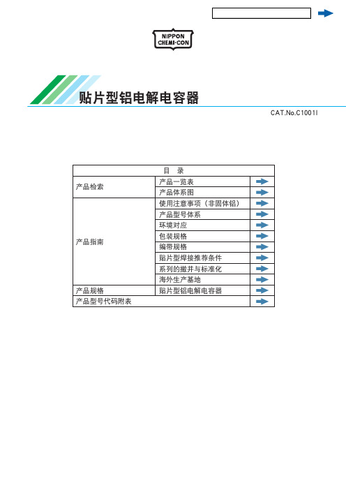
105℃超小型化品 85℃小型化品 105℃小型化品 85℃小型化标准品 105℃小型化标准品 105℃小型化标准品 85℃标准品(160Vdc以上请参照No585公报) 105℃标准品(160Vdc以上请参照No585公报) 85℃高15mm薄型品 105℃高15mm薄型品 小型化长寿命品 105℃小型化长寿命品 小型化长寿命品 长寿命品 对应异常电压·小型化高纹波品 对应异常电压·小型化品 伺服·变频器用充放电对应品(详情请参照No781公报) 85℃标准品 105℃标准品 85℃变频器高纹波小型化品 变频器用高纹波品 变频器用高耐压小型化品 变频器用高耐压品 变频器用高纹波品 变频器用长寿命品 椭圆形状·变频器用高纹波品 105℃高耐压·变频器用长寿命品 105℃变频器用高纹波长寿命品 伺服·变频器用充放电对应品(详情请参照No782公报)
铝电解电容器
产品指南
接前页
标 准
小 型 ·
低
长 寿
高 信 形状
品
薄 型 化
Z化 命
赖 性
工作上限温度· 标准寿命 (hours)
额定电压范围 (Vdc)
04 105℃
3,000 6.3 ~ 50
04 125℃ 3,000/5,000 25 ~ 50
04 125℃ 2,000~5,000 10 ~ 450
04 125℃
5,000 10 ~ 50
04 105℃
5,000
25、35
04 105℃
2,000 6.3 ~ 16
04
2088 智能板使用说明
同时按下 UP+DOWN 键将退出本模式,本模
式不修改任何参数。
按 MODE 键进入下个模式,同时放弃对本模式的修改。
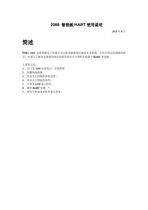
传感器供电设置(模式 03)
设置传感器供电模式。
模式代码显示区域 D3 显示 M03,
单位/状态显示区域 D4 显示 CURR,
0.000
测量值显示区域 D2 显示电流(恒流)供电电流 (mA)。
设置量程下限。
模式代码显示区域 D3 显示 M06,
单位/状态显示区域 D4 显示 LOW,
测量值显示区域 D2 系统量程下限值,闪烁处为光
0.000
标所在位置。 按 DOWN 移动光标。
当光标所在位置为数值,按 UP 键调整数值大
M06
LOW
小。 当光标所在位置为小数点,按 UP 键向左移动
操作说明
按照上图将数字板以正确的方式进行分别连接电源,传感器,确认无误后,启动电源进入上 电状态。
在系统第一次使用时,会进入系统设置状态,在正确设置并存储设置结果后,会进入测量状 态,如已正确设置,则会在上电后进入测量状态。
如系统故障,则在测量值显示区域显示 ERROR,请及时送修。
流程见下图:
上电
按 DOWN 键移动光标位置。
按 UP 键改变光标所在位置数值。 数值的变化将会引起电流的变化。如果电流输出较大,可以减小数值,以降低电流输出。
如果电流输出较小,可以增加数值,调高电流输出。 当输出电流调整至 4mA 后,同时按下 UP+DOWN 键保存,并进入下个模式 按 MODE 键进入下个状态,同时放弃对本模式的修改,并进入下个模式.
MPa
操作要点:
在测量状态下可以进行以下操作:
DS-3E0505和DS-3E0508系列吉伯特以太网开关用户手册说明书

23Symbol ConventionsThe symbols that may be found in this document are defined as follows.··During the installation and utilization of the device, please strictly conform to electrical safety rules in different nations and regions.·Ensure to use the attached power adaptor only and not to change the adaptor randomly. Please refer to specification table for specific requirements of power adaptor.·If the product does not work properly, please contact your dealer or the nearest service center. Never attempt to disassemble the camera yourself. (We shall not assume any responsibility for problems caused by unauthorized repair or maintenance.)·The device must be installed in machine room only, and only maintenance staff or qualified person should access to the device.·Do not touch the upper cover area of the device that may be overheated.·Power must be shut down during cable connection, device installation and dismantlement.·You shall acknowledge that the use of the device with Internet access might be under network security risks, please strengthen protection for your personal information and data security. If you find the device might be under network security risks, please contact with us.·Proper configuration of all passports and other security settings is the responsibility of the installer, and you shall keep user name and passports properly.·Please keep all original packing materials properly. If the product does not work properly, pack the switch in its original packing materials for shipping. We shall not assume any responsibility for damages caused by improper packing materials during shipping.45Device ConnectionInterfacesRear PanelGrounding TerminalThe grounding terminal is used to connect to the ground cable to protect the switch from lightning.Power SupplyUse the attached power cord to connect the switch to socket.Front PanelPacking List1Switch x 1Quick Start Guide x 1RJ45 Ports1000M Ethernet ports are used for devices connection via network cables .LINK/ACT Indicator RJ45 PortsIndicates a hazard with a high level of risk, which if not avoided, will result in death or serious injury.SymbolDescriptionProvides additional information to emphasize or supplement important points of the main text.Indicates a potentially hazardous situation, which if not avoided, could result in equipment damage, data loss, performance degradation, or unexpected results.PWR IndicatorGrounding TerminalPower SupplyDS-3E0505:DS-3E0508:LINK/ACT IndicatorRJ45 PortsDC 5V5/8-Port Gigabit Ethernet SwitchQuick Start GuidePower-On CheckingRegulatory InformationFCC InformationPlease take attention that changes or modification not expressly approved by the party responsible for compliance could void the user’s authority to operate the equipment.FCC compliance: This equipment has been tested and found to comply with the limits for a Class A digital device, pursuant to part 15 of the FCC Rules. These limits are designed to provide reasonable protection against harmful interference when the equipment is operated in a commercial environment. This equipment generates, uses, and can radiate radio frequency energy and, if not installed and used in accordance with the instruction manual, may cause harmful interference to radio communications. Operation of this equipment in a residential area is likely to cause harmful interference in which case the user will be required to correct the interference at his own expense.FCC ConditionsThis device complies with part 15 of the FCC Rules. Operation is subject to the following two conditions:1. This device may not cause harmful interference.2. This device must accept any interference received, including interference that may cause undesired operation.EU Conformity StatementThis product and - if applicable - the supplied accessories too are marked with "CE" and comply therefore with the applicable harmonized European standards listed under the EMC Directive 2014/30/EU, the LVD Directive 2014/35/EU,the RoHS Directive 2011/65/EU.2012/19/EU (WEEE directive): Products marked with this symbol cannot be disposed of as unsorted municipal waste in the European Union. For proper recycling, return this product to your local supplier upon the purchase of equivalent new equipment, or dispose of it at designated collection points.For more information see: 2006/66/EC (battery directive): This product contains a battery that cannot be disposed of as unsorted municipal waste in the European Union. See the product documentation for specific battery information. The battery is marked with this symbol, which may include lettering to indicate cadmium (Cd), lead (Pb),or mercury (Hg). For proper recycling, return the battery to your supplier or to a designated collection point. For more information see: Industry Canada ICES-003 ComplianceThis device meets the CAN ICES-3 (A)/NMB-3(A) standards requirements.See the following table and check whether your devices are correctly connected. After proper connection, you can use your switch without doing any settings.Please use the attached power cord in package to provide power to the The switch supports auto MDI/MDIX of ports, you can usestraight-through cable or crossover cable to connect the switch and opposite Ethernet devices.UD11864B6780100001080919Quick Start GuideALL RIGHTS RESERVED.Any and all information, including, among others, wordings, pictures, graphs are the properties of Hangzhou Hikvision Digital Technology Co., Ltd. or its subsidiaries (hereinafter referred to be “Hikvision”). This user manual (hereinafter referred to be “the Manual”) cannot be reproduced, changed, translated, or distributed, partially or wholly, by any means, without the prior written permission of Hikvision. Unless otherwise stipulated, Hikvision does not make any warranties, guarantees or representations, express or implied, regarding to the Manual.About this ManualThis Manual is applicable to DS-3E0105XX and DS-3E0109XX series 100M long-range PoE switch.The Manual includes instructions for using and managing the product. Pictures, charts, images and all other information hereinafter are for description and explanation only. The information contained in the Manual is subject to change, without notice, due to firmware updates or other reasons. Please find the latest version in the company website (/en/).Please use this user manual under the guidance of professionals.Trademarks Acknowledgementand other Hikvision’s trademarks and logos are the properties of Hikvision in various jurisdictions. Other trademarks and logos mentioned below are the properties of their respective owners.Legal DisclaimerTO THE MAXIMUM EXTENT PERMITTED BY APPLICABLE LAW, THE PRODUCT DESCRIBED, WITH ITS HARDWARE, SOFTWARE AND FIRMWARE, IS PROVIDED “AS IS”, WITH ALL FAULTS AND ERRORS, AND HIKVISION MAKES NO WARRANTIES, EXPRESS OR IMPLIED, INCLUDING WITHOUT LIMITATION, MERCHANTABILITY, SATISFACTORY QUALITY, FITNESS FOR A PARTICULAR PURPOSE, AND NON-INFRINGEMENT OF THIRD PARTY. IN NO EVENT WILL HIKVISION, ITS DIRECTORS, OFFICERS, EMPLOYEES, OR AGENTS BE LIABLE TO YOU FOR ANY SPECIAL, CONSEQUENTIAL, INCIDENTAL, OR INDIRECT DAMAGES, INCLUDING, AMONG OTHERS, DAMAGES FOR LOSS OF BUSINESS PROFITS, BUSINESS INTERRUPTION, OR LOSS OF DATA OR DOCUMENTATION, IN CONNECTION WITH THE USE OF THIS PRODUCT, EVEN IF HIKVISION HAS BEEN ADVISED OF THE POSSIBILITY OF SUCH DAMAGES.REGARDING TO THE PRODUCT WITH INTERNET ACCESS, THE USE OF PRODUCT SHALL BE WHOLLY AT YOUR OWN RISKS. HIKVISION SHALL NOT TAKE ANY RESPONSIBILITES FOR ABNORMAL OPERATION, PRIVACY LEAKAGE OR OTHER DAMAGES RESULTING FROM CYBER ATTACK, HACKER ATTACK, VIRUS INSPECTION, OR OTHER INTERNET SECURITY RISKS; HOWEVER, HIKVISION WILL PROVIDE TIMELY TECHNICAL SUPPORT IF REQUIRED.SURVEILLANCE LAWS VARY BY JURISDICTION. PLEASE CHECK ALL RELEVANT LAWS IN YOUR JURISDICTION BEFORE USING THIS PRODUCT IN ORDER TO ENSURE THAT YOUR USE CONFORMS THE APPLICABLE LAW. HIKVISION SHALL NOT BE LIABLE IN THE EVENT THAT THIS PRODUCT IS USED WITH ILLEGITIMATE PURPOSES.IN THE EVENT OF ANY CONFLICTS BETWEEN THIS MANUAL AND THE APPLICABLE LAW, THE LATER PREVAILS.。
CSC-280系列数字式保护(测控)装置说明书(0SF.451.069)_V2.0
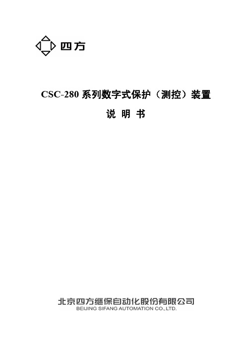
2.7
ห้องสมุดไป่ตู้
输出触点容量............................................................................................................................ 4
2.8
装置主要技术参数.................................................................................................................... 4
1.1
适用范围 ................................................................................................................................... 1
1.2
装置主要特点............................................................................................................................ 1
技术支持
电话:010-62986668 传真:010-62981900
重要提示
感谢您使用北京四方继保自动化股份有限公司的产品。为了安全、 正确、高效地使用本装置,请您务必注意以下重要提示:
1) 本说明书仅适用于 CSC-280 系列数字式保护(测控)装置。 2) 请仔细阅读本说明书,并按照说明书的规定调整、测试和操作。如
3.6
人机接口(MMI) ................................................................................................................... 7
施乐2056 2058维修手册dc2058_sc_ver1_chap09

3. 拔出电源插头。
警告
维修机器时, 请关闭主电源开关, 并拔出电源插头。 4. 安装 Platen Cover。 (Figure 2)
Figure 3 j0xh40101
6. 插入电源插头, 打开电源开关。
Version 1.0
DC 2056/2058
9.1.3 安装 DADF
产品代码 · EC102045
安装步骤 1. 确认包装随附品。 (Figure 1)
编号
1 2 3 4
名称
DADF Platen Cushion Label 安装说明书
Table 1
数量
1 1 4 1
· Item 4 没有图例说明。
Figure 1 j0sg90101
2. 关闭电源开关, 确认画面显示消失。
注意
关闭电源开关时, 请确认 [ 数据 ] 指示灯已熄灭。ຫໍສະໝຸດ 299 安装 / 拆卸
Version 1.0
DC 2056/2058
2011/10 9-1
安装 / 拆卸
安装 / 拆卸
2011/10 9-2
DC 2056/2058
Version 1.0
9.1.1 机器的安装
前言
Platen Cover 及 DADF 是安装机器时, 必须配合顾客选择安装的必要选购品。 备妥要安装 的选购品, 并参照下述第 9 章的步骤, 一次完成整个安装作业。 - 9.1.2 安装 Platen ( 产品代码 : EC102044) - 9.1.3 安装 DADF ( 产品代码 : EC102045) 有关其他选购品的详情, 请参照第 9 章的各个项目。
数量 1 1
3. 请参照第 9 章的项目安装 Platen Cover 或 DADF。 4. 打开 Front Cover。 5. 左右摇动 Toner Cartridge 数次, 再加以安装。 (Figure 1)
20583-2020标准豆丁

20583-2020标准豆丁标准豆丁20583-2020引言:标准豆丁20583-2020是关于豆丁产品规范的标准。
本标准旨在规范豆丁产品的质量要求、技术要求和测试方法,以保障消费者的权益,促进豆丁产业的快速发展。
本文将从标准的背景、应用范围、主要内容和实施方法等方面进行详细阐述。
一、标准的背景豆丁是一种以豆类为原料,经过研磨、调制等工艺制成的食品,具有高营养价值和多种口感选择。
近年来,随着人们对健康饮食的追求和对新奇口感的需求,豆丁市场逐渐兴起。
然而,由于缺乏统一的生产标准,豆丁产品市场存在着质量良莠不齐的问题,给消费者的购买带来了困扰。
因此,制定一项豆丁产品的标准显得尤为必要。
二、应用范围本标准适用于豆丁产品的生产、加工和质量监督等环节。
豆丁产品包括但不限于豆丁饼、豆丁豆腐和豆丁干等。
三、主要内容1.术语和定义:本节列出了豆丁产品常用的术语和定义,以便在标准实施中统一理解。
2.产品分类和命名:本节对豆丁产品进行了分类,并规定了不同产品的命名方式,以便消费者正确识别。
3.质量要求:本节规定了豆丁产品的外观、色泽、气味、口感、营养成分等质量要求。
例如,豆丁产品应当具有均匀的颜色和细腻的口感,不得有异味和霉变。
4.技术要求:本节规定了豆丁产品的生产工艺流程、原料选用、搅拌方式等技术要求。
例如,豆丁产品的生产过程应具备合理的工艺环境,使用安全卫生的原料。
5.检验方法:本节列举了豆丁产品质量检验的相关方法和指标,包括豆丁产品外观检验、水分含量测定、蛋白质含量测定等。
6.标志、包装、储存和运输:本节规定了豆丁产品在标志、包装、储存和运输方面的要求,以保障产品的质量和食品安全。
四、实施方法为了保证标准的有效实施,本标准还规定了相关部门对豆丁产品的监督检查工作。
监管部门应当按照标准要求对豆丁生产企业进行定期检查和抽检,确保豆丁产品质量符合标准要求。
同时,消费者也可以通过举报电话等方式向监管部门反映问题,维护自身权益。
Digi 设备商品说明书

!"
#
1.1 Overview .......................................................................................................................................... 4 1.2 Features of the UART Application Kit............................................................................................ 4 1.3 Conventions...................................................................................................................................... 4 1.4 Acronyms and abbreviations ........................................................................................................... 5
Variables to be replaced with actual values are shown in italics.
4ቤተ መጻሕፍቲ ባይዱ
UART Application Kit for Windows Embedded CE 6.0 - User's Manual
Style Menu name > option
UL SUBJECT 2058 中文版
UL2058高安全性电子锁检测标准(草案)目录简介1.范围2.概述2.1测量单位2.2元件3.术语4.安装和操作说明结构5.概述6.非金属部件7.装配8.防腐蚀9.现场接线9.1现场接线端子9.2一般应用9.3特殊应用9.4现场接线引线头10.内部布线10.1通用要求10.2布线方式11.电气元件11.1元件装配11.2绝缘材料11.3载流元件11.5过流保护11.6半导体器件11.7开关11.8变压器和线圈12.间距性能13.概述13.1测试设备和数据13.2测试电压14.正常操作测试15.操作测试16.防非授权开启17.抗干扰测试17.1概述17.2短路测试17.30~100V外加DC电压测试17.4100~1000V外加DC电压测试17.5噪音尖峰17.6静电放电(ESD)17.7低压、低频交流测试17.8高压、低频交流测试17.9高压、高频交流测试17.10机械冲击18.输入测量值19..备用电源20.欠压运行测试21.过压运行测试22.环境适应性测试23.湿度测试24.过负荷测试25.耐久性测试26.冲击测试27.温升测试28.电容可靠性测试29.电池更换测试30.拉力测试31.外壳强度测试32.特殊端子装配测试32.1概述32.2插拔力测试32.3弯曲测试32.4毫伏压降测试32.5温升测试33.振动测试户外使用34.概述35.淋雨测试36.防尘测试37.标记38.概述39.配件40.概述41.结构42.性能测试43.标记附录A简介1范围1.1此要求涵盖使用在保险柜、保险箱门上的高安全性电子锁具及类似的用锁舌闭合的方式来抵抗非授权开启的设备。
1.2此要求旨在检测一定时间范围内高安全电子锁具抵抗非授权开启的能力,故电子锁可以不具备完整的防外力破坏的能力。
1.3此要求适用于以电池供电、或CLASS2AC-DC供电、或自发电的高安全性电子锁具,如果电子锁是通过连接至高电压(30-600V)的电源装置供电,则需满足UL603防盗报警系统用电源装置的相关要求。
施乐2056 2058维修手册dc2058_sc_ver1_chap07

第七章电气配线数据2011/107-1DC 2056/2058电气配线数据Version 1.07 电气配线数据7.1 Plug/Jack Location List7.1.1 Plug/Jack Location List..............................................37.1.2 Plug/Jack Location...................................................62011/107-2Version 1.0DC 2056/2058电气配线数据2011/107-3DC 2056/2058电气配线数据7.1 Plug/Jack Location ListVersion 1.07.1.1 Plug/Jack Location ListHow to Use the Plug/Jack Location List· 要找到连接器的安装位置,应参照“7.1.1 插头/插座位置列表”,找到Figure No.和Item No.,然后再参照“7.1.2 插头/插座位置” 图表。
· “7.1.1 插头/插座位置列表”的P/J No. 用以下五种方式表示:· J250表示Jack 250。
· P250表示Plug 250。
· 无P 或者J 的数字表示Jack 与Plug 二者。
· CN1表示连接器1。
· FS1表示Faston Terminal 1。
Figure 1 7001Plug/Jack Location ListTable 1 Plug/Jack Location ListP/J No.Figure Item No.Remarks (where to connect) P/J11212LVPS J1177FAX PWB P2013UI PWB 1 J2174FAX PWB P31210LVPS J3176FAX PWB P/J4012UI PWB 2P/J41214LVPS (220-240V Only) J4175FAX PWB (Micro SD)P/J5011UI FAX Button PWB (Option) J5173FAX PWB P/J6129LVPS P/J71211LVPSP101028ESS/MCU PWB P201029ESS/MCU PWB P301027ESS/MCU PWBJ50128Inlet GFI BreakerJ56124Main Power Switch (BLK) J57121Main Power Switch (BLK) J68123Main Power Switch (WHT) J69122Main Power Switch (WHT) J72127Inlet GFI Bleaker P/J101094Tray1 No Paper SensorP/J101A 152Tray4 Nudger Level Sensor (2TM) P/J101B 152Tray3 Nudger Level Sensor (2TM) P/J101C 132Tray2 Nudger Level Sensor (1TM) P/J1020510Toner CRUM PWBP/J102A 153Tray4 No Paper Sensor (2TM) P/J102B 153Tray3 No Paper Sensor (2TM) P/J102C 133Tray2 No Paper Sensor (1TM) P/J104093Regi. SensorP/J107081MSI No Paper Sensor P/J108082MSI Paper Size Sensor P/J1091110Tray1 Size Sensor2011/107-4Version 1.07.1 Plug/Jack Location ListDC 2056/2058电气配线数据P/J120112L/H Cover Interlock Switch P/J1211213Front Cover Interlock Switch P/J125051Fusing Unit Exit Sensor P/J130053ROS Motor P/J131063Thermistor P/J140057LD PWBP/J142072Duplex Wait Sensor P/J143071Duplex Cover Switch P/J144073Duplex ClutchP/J150092Temp And Humidity Sensor P/J160056LD PWB P/J201058LD PWBP/J205083MSI Feed Solenoid P/J2071014ESS/MCU PWBP/J208113Main Drive Motor (2pin) P/J209114Main Drive Motor (8pin) P/J213111Nohad Fan P/J215091Regi. ClutchP/J216054Toner Dispence Motor P/J217117Tray1 Feed Clutch P/J218109ESS/MCU PWBP/J220A 151Tray4 Feed/Lift Up Motor (2TM) P/J220B 151Tray3 Feed/Lift Up Motor (2TM) P/J220C 131Tray2 Feed/Lift Up Motor (1TM) P3521111 P353174FAX PWB P/J4001019ESS/MCU PWB P/J4011020ESS/MCU PWB P/J402101ESS/MCU PWB P/J4031015ESS/MCU PWB P404108ESS/MCU PWB P/J4051018ESS/MCU PWB P/J406106ESS/MCU PWB P/J4071016ESS/MCU PWB P/J4081013ESS/MCU PWB P/J409105ESS/MCU PWB P/J4101012ESS/MCU PWBTable 1 Plug/Jack Location ListP/J No.Figure Item No.Remarks (where to connect) P/J4111021ESS/MCU PWB P/J4121023ESS/MCU PWB P/J4131017ESS/MCU PWB P413C 148STM PWB J413C 1512 P/J4151022ESS/MCU PWB P/J4161010ESS/MCU PWB P/J418102ESS/MCU PWB P/J419103ESS/MCU PWB P/J4201011ESS/MCU PWB P/J421107ESS/MCU PWB P/J422104ESS/MCU PWB P4251030ESS/MCU PWB J425172NET I/F PWB P/J4411024ESS/MCU PWB J4421025ESS/MCU PWB P4421710 J4431026ESS/MCU PWB J444171NET I/F PWBP450118 J450138 P/J500059HVPS P/J522125LVPS P/J523126LVPS P/J5411622TM PWB P/J541C 141STM PWB P/J5481612TM PWB P/J548C 146STM PWB P/J5491672TM PWB P/J549C 145STM PWB P/J5521682TM PWB P/J552C 147STM PWB P/J5541632TM PWB P600062Fusing UnitJ600061 P/J605116 P/J606115Table 1 Plug/Jack Location ListP/J No.Figure Item No.Remarks (where to connect)2011/107-5DC 2056/2058电气配线数据7.1 Plug/Jack Location ListVersion 1.0P/J608084 P/J6150511Drum CartridgeP/J620055 P/J661A 158Connector(2TM) P/J661B 159Connector(2TM) P/J661C 136Connector(1TM) P/J700043CCD Lens Assembly P/J710014UI PWB 1P/J7200411IIT Trans PWB P/J721042IIT Trans PWB P/J7220410IIT Trans PWB P/J723041IIT Trans PWB P/J7240415IIT Trans PWB P/J7510312DADF PWB P/J7520311DADF PWB P/J7530310DADF PWB P/J754034DADF PWB P/J755039DADF PWB P/J756033DADF PWB P/J757031DADF PWB P/J758032DADF PWB P7600313DADF PWBP/J7610220Document Tray Size Sensor 1P/J762023Document Tray Set Guide Sensor 3P/J763022Document Tray Set Guide Sensor 2 (BLU Connector)P/J764021Document Tray Size Sensor 2P/J7650219Document Tray Set Guide Sensor 1 P/J7660211Connector (10pin) P/J767024DADF APS Sensor 3 P/J768025DADF APS Sensor 2 P/J769026DADF APS Sensor 1 P/J7700210Connector (9pin)P/J771035DADF Document Set Sensor P/J772036DADF Feed Out Sensor P/J773027DADF Invert SensorTable 1 Plug/Jack Location ListP/J No.Figure Item No.Remarks (where to connect) P/J774029DADF Pre Regi. Sensor P/J775028DADF Regi. Sensor P/J776038DADF Feed Motor P/J777037DADF Regi. MotorP/J7780215Exit Nip Release SolenoidP/J7790214DADF Gate Solenoid (BLU Connector) P/J7800216Stamp Solenoid (Option) P/J7910221DADF Document Set LED J8021711FAX PWB (LINE) J804179FAX PWB (TEL) J805178FAX PWB J8061712FAX PWB J8071713FAX PWBP/J812C 137STM Left Cover Switch P/J81315112TM Left Cover SwitchP/J820154Tray3 Paper Size Switch (2TM) P/J820C 134Tray2 Paper Size Switch (1TM) P/J821157Tray3 Feed Out Sensor (2TM) P/J821C 135Tray2 Feed Out Sensor (1TM) P/J8221652TM Takeaway Roll Clutch P/J822C 144STM Takeaway Roll ClutchP/J824155Tray4 Paper Size Switch 4(2TM) P/J825156Tray4 Feed Out Sensor (2TM) P/J8261662TM Takeaway Motor P/J826C 142STM T/A Motor P/J841164Connector (2TM) P/J841C 143Connector (1TM) P/J8421510Connector (2TM) P/J9990512Durm CRUM PWB P/J2011052SOS PWB P/J2071119Exit Motor P/J7001046LED Lamp PWB P/J71920414IIT Trans PWBP/J7251049Platen Close Sensor P/J7252048Platen Angle Sensor P/J7253047IIT Regi. SensorTable 1 Plug/Jack Location ListP/J No.Figure Item No.Remarks (where to connect)2011/107-6Version 1.07.1 Plug/Jack Location ListDC 2056/2058电气配线数据7.1.2 Plug/Jack LocationFigure 1 Control Panel (j0xh71001)P/J7254044APS Sensor 1 P/J7256045APS Sensor 2 P/J72580416Carriage Motor P7*******IIT Trans PWB P7*******IIT Trans PWB J75110218 J75210217ConnectorF10213DADF Interlock Switch F20212DADF Interlock Switch FS10064ThermostatTable 1 Plug/Jack Location ListP/J No.Figure Item No.Remarks (where to connect)2011/107-7DC 2056/2058电气配线数据7.1 Plug/Jack Location ListVersion 1.0Figure 2 DADF 1of2 (j0xh71002)Figure 3 DADF 2of2 (j0xh71003)2011/107-8Version 1.07.1 Plug/Jack Location ListDC 2056/2058电气配线数据Figure 4 IIT (j0xh71004)Figure 5 Front View (j0xh71005)Figure 6 Fusing Unit (j0xh71006)Figure 7 Duplex (j0xh71007)2011/107-10Version 1.07.1 Plug/Jack Location ListDC 2056/2058电气配线数据Figure 8 MSI (j0xh71008)Figure 9 Regi. (j0xh71009)Figure 10 ESS/MCU PWB (j0xh71010)Figure 11 Rear View (j0xh71011)2011/107-12Version 1.07.1 Plug/Jack Location ListDC 2056/2058电气配线数据Figure 12 LVPS (j0xh71012)Figure 13 1TM 1of2 (j0xh71013)Figure 14 1TM 2of2 (j0xh71014)Figure 15 2TM 1of2 (j0xh71015)2011/107-14Version 1.07.1 Plug/Jack Location ListDC 2056/2058电气配线数据Figure 16 2TM 2of2 (j0xh71016)Figure 17 17 NET PWB/FAX PWB (j0xh71017)7.2 Wire NetworkContents7.2Wire Network7.2.1 ACH (1)7.2.2 ACN (2)7.2.3 +2.5VDC (3)7.2.4 2.5VRTN (4)7.2.5 +3.3VDC-1 (5)7.2.6 +3.3VDC-2 (6)7.2.7 3.3VRTN-1 (7)7.2.8 3.3VRTN-2 (8)7.2.9 +5VDC-1 (9)7.2.10 +5VDC-2 (10)7.2.11 5VRTN-1 (11)7.2.12 5VRTN-2 (12)7.2.13 +24VDC-1 (13)7.2.14 +24VDC-2 (14)7.2.15 +24VDC-3 (15)7.2.16 24VRTN (16)7.2.17 IIT +3.3/+5/+24VDC (17)7.2.18 IIT 3.3/5/24VRTN (18)7.2.19 DADF +5VDC (19)7.2.20 DADF 5VRTN (20)7.2.21 DADF +24VDC (21)7.2.22 DADF 24VRTN (22)Contents iii7.2 Wire NetworkContentsBlank7.2.1ACHj0xh72001Chapter 7 Wiring Data7.2 Wire Network7.2.2ACN7-27.2.3+2.5VDCj0xh720037-4Chapter 7 Wiring Data7.2 Wire Network7.2.42.5VRTN7.2.5+3.3VDC-1j0xh72005Chapter 7 Wiring Data7.2 Wire Network7.2.6+3.3VDC-27-67.2.73.3VRTN-1j0xh720077-8Chapter 7 Wiring Data7.2 Wire Network7.2.83.3VRTN-27.2.9+5VDC-1j0xh72009Chapter 7 Wiring Data7.2 Wire Network7.2.10+5VDC-27-107.2.115VRTN-1j0xh72011Chapter 7 Wiring Data7.2 Wire Network7.2.125VRTN-27-127.2.13+24VDC-1Chapter 7 Wiring Data7.2 Wire Network7.2.14+24VDC-27-147.2.15+24VDC-3j0xh720157-16Chapter 7 Wiring Data7.2 Wire Network7.2.1624VRTN7.2.17IIT +3.3/+5/+24VDCj0xh720176.26.16.16.36.16.17-18Chapter 7 Wiring Data7.2 Wire Network6.26.36.16.16.16.13.17.2.19DADF+5VDCj0xh72019Chapter 7 Wiring Data7.2 Wire Network7.2.20DADF 5VRTN7-207.2 Wire Network7.2.21DADF +24VDCj0xh720215.55.6Chapter 7 Wiring Data7.2 Wire Network7.2.22DADF 24VRTNj0xh720227-227.3 BSDContents7.3.1 Preface (1)7.3.1.1 How to Use the BSDs (1)7.3.1.2 Explanation of Symbols (1)7.3.1.3 Signal Name (2)7.3.1.4 DC Voltage (2)7.3.1.5 Other Descriptions (2)Chain 1 Standby PowerCH1.1 MAIN POWER ON (3)CH1.2 M/C POWER CONTROL (4)CH1.3 DC POWER GENERATION (+3.3VDC) (5)CH1.4 DC POWER GENERATION (+5VDC) (6)CH1.5 DC POWER GENERATION (+24VDC) (7)CH1.6 IIT/DADF DC POWER DISTRIBUTION (8)CH1.7 POWER INTERLOCK SWITCHING (1 OF 2) (9)CH1.8 POWER INTERLOCK SWITCHING (2 OF 2) (10)Chain 2 Mode SelectionCH2.1 CONTROL PANEL (11)Chain 3 Machine Run ControlCH3.1 PWB COMMUNICATION (ESS/MCU-IIT) (12)CH3.2 PWB COMMUNICATION (ESS/MCU-DADF) (13)CH3.3 PWB COMMUNICATION (ESS/MCU-TM) (14)CH3.4 PWB COMMUNICATION (ESS/MCU-NET) (15)CH3.5 ELECTRIC BILLING (16)Chain 4 Start Print PowerCH4.1 MAIN DRIVE CONTROL....................................................................................................................................17 Chain 5 Document TransportationCH5.1 DOCUMENT SETTING (18)CH5.2 DOCUMENT SIZE SENSING (1 OF 2) (19)CH5.3 DOCUMENT SIZE SENSING (2 OF 2) (20)CH5.4 DOCUMENT FEED (1 OF 2) (21)CH5.5 DOCUMENT FEED (2 OF 2) (22)CH5.6 DOCUMENT SCAN AND INVERT (23)CH5.7 DOCUMENT EXIT TRANSPORTATION (24)CH5.8 DOCUMENT PATH (25)CH5.9 DOCUMENT TRANSMISSION (26)Chain 6 ImagingCH6.1 PLATEN DOCUMENT SENSING (27)CH6.2 DOCUMENT ILLUMINATION (28)CH6.3 CARRIAGE CONTROL (29)CH6.4 IMAGE INPUT (30)CH6.5 LASER CONTROL (31)Chain 7 Paper SupplyingCH7.1 TRAY 1 PAPER SIZE SENSING (32)CH7.2 TRAY 2 PAPER SIZE SENSING (1TM) (33)CH7.3 TRAY 3 PAPER SIZE SENSING (2TM) (34)CH7.4 TRAY 4 PAPER SIZE SENSING (2TM) (35)CH7.5 MSI PAPER SIZE SENSING (36)CH7.6 TRAY 1 PAPER STACKING (37)CH7.7 TRAY 2 PAPER STACKING (1TM) (38)CH7.8 TRAY 3 PAPER STACKING (2TM) (39)CH7.9 TRAY 4 PAPER STACKING (2TM) (40)CH7.10 MSI PAPER STACKING (41)Contentsii 7.3 BSDContents Chain 8 Paper TransportationCH8.1 TRAY 1 AND MSI PAPER TRANSPORTATION (42)CH8.2 TRAY MODULE PAPER TRANSPORTATION (1TM) (43)CH8.3 TRAY MODULE PAPER TRANSPORTATION (2TM) (44)CH8.4 REGISTRATION (45)CH8.5 PAPER PATH (46)Chain 9 MarkingCH9.1 XERO AND TONER LIFE CONTROL (47)CH9.2 CHARGING AND EXPOSURE (48)CH9.3 TONER DISPENSE AND DEVELOPMENT (49)CH9.4 IMAGE TRANSFER AND STRIPPING (50)Chain 10 Fusing and Copy TransportationCH10.1 FUSING HEAT CONTROL (1 OF 2) (51)CH10.2 FUSING HEAT CONTROL (2 OF 2) (52)CH10.3 FUSING (53)CH10.4 EXIT PAPER TRANSPORTATION (54)CH10.5 DUPLEX TRANSPORTATION (55)Chain 34 FAXCH34.1 FAX (56)7.3.1Preface7.3.1.1How to Use the BSDs Indicates a mechanical connection to a part.Indicates that a mechanical drive signal goes in theTP17.3.1 Preface7-27.3 BSD 7.3.1 PrefaceIndicates switch and is also used as Interlock Switch.Indicates the Cheater type of Interlock Switch.Indicates the Chip Fuse.7.3.1.3 Signal NameSignal name structure ・ Input componentPAPER SENSED (L) +5VDCOperation state Logical value Voltage with signal (H) The example indicates that when paper is sensed, this signal level is (L) and that otherwise, the signal level is (H) with the voltage +5VDC. ・ Outout componentsON (L) +24VDCOperation state Logical value Voltage with signal (H)The example indicates that when the part is ON, thesignal level is (L) and that when it is OFF , the signal level is (H) with the voltage +24VDC.7.3.1.4 DC VoltageA measurement of DC voltage is made between the particular test point and the frame unless otherwise specified by note and test data. The measured DC voltage is in the range below:Voltage Level Range +3.3VDC (H) +3.2~+3.6VDC +5VDC (H) +4.8~+5.4VDC +24VDC(H)+23.3~+25.7VDC7.3.1.5 Other DescriptionsDC330 Input Component Voltage LevelThe voltage levels (H/L) shown on the BSDs are the levels that are measured by the tester. Some of them are therefore different from H/L displayed on the PSW.Wiring ColorWires are distinguished by color in part of the BSDs for this model. The colors of wires are shown below the signal lines in their respective abbreviations listed below:Abbreviation ColorBRN Brown RED Red ORN Orange YEL Yellow GRN Green BLU Blue VIO Violet GRY Gray WHT White BLK Black GRN/YEL Green/Yellow PNK Pink SKY SkyFigures on the BSDsThe grayed-out portion of the figure shows the path from Motor or Solenoid to parts to drive.Chain1 Standby Power7-47.3 BSDChain1 Standby Power。
sd2058时钟芯片的技术文档
寄存器
5.1 寄存器列表
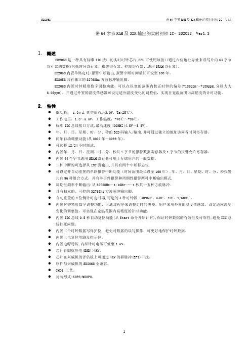
寄存器名 称 秒 分钟 小时 星期 日 月 年 秒报警 分钟报警 小时报警 星期报警 日报警 月报警 年报警 报警允许 CTR1 CTR2 CTR3 时间调整 倒计时定 TD7 时器 TD6 TD5 TD4 TD3 TD2 TD1 TD0 0-255 0000-0000 D7 0 0 12_/24 0 0 0 Y80 0 0 0 0 0 0 AY7 0 WRTC3 WRTC1 ARST 0 D6 S40 MN40 0 P/A_ 0 0 0 Y40 AS40 AMN40 0 AP/A_ AW6 0 0 AY6 EAY 0 IM 32K F6 AW5 AD20 0 AY5 EAMO INTAF INTS1 TDS1 F5 AW4 AD10 AMO10 AY4 EAD INTDF INTS0 TDS0 F4 AW3 AD8 AMO8 AY3 EAW 0 0 FS3 F3 AW2 AD4 AMO4 AY2 EAH WRTC2 INTDE FS2 F2 AW1 AD2 AMO2 AY1 EAMN 0 INTAE FS1 F1 AW0 AD1 AMO1 AY0 EAS RTCF INTFE FS0 F0 N/A 1-31 1-12 0-99 N/A N/A N/A N/A N/A 0000-0000 0000-0000 0000-0000 0000-0000 0000-0000 0000-0000 0000-0000 0000-0000 0000-0000 0 D20 0 Y20 AS20 AMN20 AH20 AH10 AH8 AH4 AH2 AH1 0-23 0000-0000 0 D10 MO10 Y10 AS10 AMN10 0 D8 MO8 Y8 AS8 AMN8 W4 D4 MO4 Y4 AS4 AMN4 W2 D2 MO2 Y2 AS2 AMN2 W1 D1 MO1 Y1 AS1 AMN1 0-6 1-31 1-12 0-99 0-59 0-59 XXXX-XXXX XXXX-XXXX XXXX-XXXX XXXX-XXXX 0000-0000 0000-0000 D5 S20 MN20 H20 H10 H8 H4 H2 H1 0-23 XXXX-XXXX D4 S10 MN10 BIT D3 S8 MN8 D2 S4 MN4 D1 S2 MN2 D0 S1 MN1 数值范围 (十进制) 0-59 0-59 缺省值 (二进制) XXXX-XXXX XXXX-XXXX
利尔达蓝牙模块BLEMesh LSD4BT-K53系列规格书_V1.10

·兼容性 - 设计侧插、邮票孔兼容的接口方式
·BLE 功能 - 支持 BLE 5.0 - 支持 125Kbps、500Kbps、1Mbps、2Mbps
·Mesh 协议 - Bluetooth SIG Mesh 支持 - Telink 专有的 Mesh 支持
3 / 15
图片索引
图1 图2 图3 图4 图5 图6 图7 图8 图9 图 10 图 11 图 12
LSD4BT-K53 系列实物图................................................................................................ 6 LSD4BT-K53 系列尺寸图................................................................................................ 6 典型应用电路................................................................................................................. 8 模组天线选择电路......................................................................................................... 9 模组天线净空区............................................................................................................. 9 PCB 天线在板框外........................................................................................................ 10 PCB 天线沿板边放置且下方挖空................................................................................ 10 PCB 天线沿板边放置且下方均不敷铜........................................................................ 10 模块背面标签图例....................................................................................................... 11 回流焊作业指导........................................................................................................... 13 料带尺寸....................................................................................................................... 14 产品包装方向............................................................................................................... 15
DTC数字教室规格书
DTC数字教室1、产品介绍与特点:集合所有数字教学的设备和功能。
交互白板、投影、电脑、音箱、实物展台、中控、粉笔或水笔书写通过模块有机整合,浑然一体。
人性化的电子课桌,具备了同步数显、资源分享、授权控制、数字作业等多种功能通过WI-FI、局域网、互联网实现同学之间、师生之间、家长之间全方位互动。
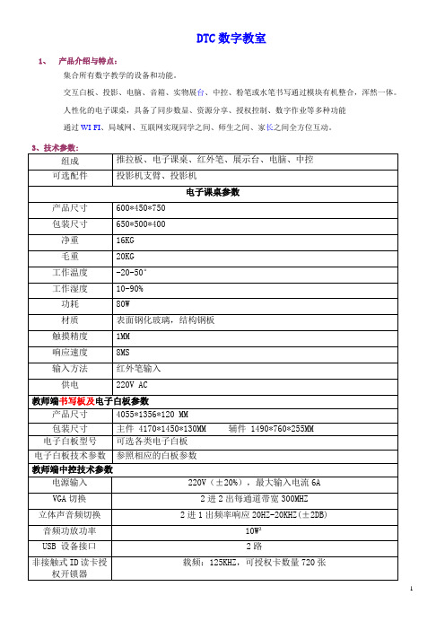
3、技术参数:组成推拉板、电子课桌、红外笔、展示台、电脑、中控可选配件投影机支臂、投影机电子课桌参数产品尺寸600*450*750包装尺寸650*500*400净重16KG毛重20KG工作温度-20-50°工作湿度10-90%功耗80W材质表面钢化玻璃,结构钢板触摸精度1MM响应速度8MS输入方法红外笔输入供电220V AC教师端书写板及电子白板参数产品尺寸4055*1356*120 MM包装尺寸主件 4170*1450*130MM 辅件 1490*760*255MM 电子白板型号可选各类电子白板电子白板技术参数参照相应的白板参数教师端中控技术参数电源输入220V(±20%),最大输入电流6AVGA切换2进2出每通道带宽300MHZ立体声音频切换2进1出频率响应20HZ-20KHZ(±2DB)音频功放功率10W²USB 设备接口2路载频:125KHZ,可授权卡数量720张非接触式ID读卡授权开锁器教师端音响技术参数音频功率放大器 2.1声道,中高音左右声道有效功率10WX2,低音声道有效功率20W无线话筒 2.4G数字无线音频传输,有效传输距离10M教师端高拍仪技术参数分辨率最高分辨率1600*1200拍摄区域面积大小A4教师端电脑配置参数项目型号配置规格CPU ITEL E3300 双核 2.4 GHZ、内存金士顿 2G DDR3 内存主频1333硬盘富士通SATA 250G电源长城电源220W 宽频宽压电源1、图片:。
Sensata Technologies APL UPL系列产品说明说明书

“Existing Design-In Only”A P L /U P LINTRODUCTIONIMPORTANT NOTICE: The APL/UPL is a legacy product and no new design-in orders are being accepted. We are also discontinuing the 205 series (APL with dust proof enclosure). If the specifications for any of these products are necessary for your system, Sensata T echnologies recommends utilizing the Airpax™ IAL series.The APL/UPL magnetic circuit protector provides reliable, low-cost power switching, circuit protection and circuit control. The handle opens and closes a circuit, under normal load conditions, similar to an ON-OFF switch. Upon overload, the internal mechanism trips, opens the contacts and forcibly returns the handle to the OFF position. Since the protector is “trip free,” the internal contacts will not remain closed in the presence of an overload, even though the handle is held in the ON position.The APL/UPL line offers many configurations including series, shunt and relay with a choice of delays and ratings. APL/UPL multi-pole assemblies are available with a mix of current ratings, delays and internal circuit configurations.While designed for industrial, military and information processing applications, the APL is suitable for use in any situation where precision operation is required. Most versions of the APL family are recognized by UL per UL STD. 1077 as supplementary protectors and certified by CSA per CSA STD. C22.2–No. 235as supplementary protectors and are designated with the UPL prefix..675Note: Tolerance ± .015 [.38]unless noted. Dimensions inbrackets [ ] are millimeters.MULTI-POLE CIRCUIT PROTECTORSMulti-pole protectors are combined in an assembly with the actuating handles linked and the trip mechanisms internally coupled. A fault in either protected circuit opens all poles simultaneously. Applications include use in two-phase circuits, single-phase three-wire systems or in two or more related but electrically isolated circuits. A mix of delays, ratings and configurations is possible, with the series type having any of the auxiliary switches listed. Combinations up to nine poles are available.(SEE TABLE)“A”.75 ± .015[19.05 ± .38](TYP)ONON1.448[36.78].432[10.97]2.280[57.91].750[19.05].432[10.97]1.448[36.78]2.060[52.32]1.530[38.86]Ø 4X .156[3.96].432[10.97]1.448[36.78]Ø 2X .156[3.96].755[19.18]2.060[52.32].750[19.05].750[19.05]2.060[52.32]Ø 6X .156[3.96]One PoleTwo PoleThree PoleMounting Details Panel Mounting Tolerances: ±.005 [.13] unless noted.MULTI-POLE DIMENSIONS2 pole “A” 1.515 [38.48] max3 pole “A” 2.265 [57.53] max4 pole “A” 3.015 [76.58] max 5 pole “A” 3.765 [95.63] max6 pole “A” 4.515 [114.68] max7 pole “A” 5.265 [133.73] max8 pole “A” 6.015 [152.78] max9 pole “A”6.765 [171.83] maxNote: Dimension “A” varies with # of polesA P L /U P LSeries TripThe most popular configuration for magnetic protectors is the series trip where the sensing coil and contacts are in series with the load being protected. The handle position conveniently indicates circuit status. In addition to providing conventional over-current protection, it’s simultaneously used as an on-off switch.Auxiliary Switch(Applies to Series Trip Only)This is furnished as an integral part of a series pole in single or multi-pole assemblies. Isolated electrically from the protector’s circuit, the switch works in unison with the power contacts and provides indication at a remote location of the protector’s on-off status.Auxiliary switch contacts actuate simultaneously with the main breaker contacts, and will open regardless of whether the breaker contacts are opened manually or electrically. For auxiliary switch ratings below 6Vac or 5Vdc, an auxiliary switch with gold contacts is available. Gold contacts are not recommended for load current above 100 milliamps.The contacts on our optional RS auxiliary switch will open only in the event of an electrical trip of the circuit breaker.Shunt TripThe shunt trip is designed for controlling two separate loads with one assembly. The control is established by providing overload protection for the critical load. When the current through this load becomes excessive and reaches the trip point, the protector will open and remove power from both loads simultaneously. The total current rating of both loads must not exceed the maximum contact rating.Relay TripThis permits the overload sensing coil to be placed in a circuit which is electrically isolated from the trip contacts. The coil may be actuated by sensors monitoring pressure, flow, temperature, speed, etc. Other typical applications include crowbar, interlock and emergency/rapid shutdown circuitry. Trip may be accomplished by voltage or current, which must be removed immediately upon tripping.Dual CoilDual coil protectors provide remote shut down option and normal overcurrent protection in the confines of a single breaker pole. This construction saves space by eliminating the need for an additional pole for the voltage trip function.Voltage TripSometimes called “dump circuits” or “panic trip circuits,” these units make it possible to open main power contacts with lower power inputs from one or more sources. This configuration is becoming increasingly more important for sensitive circuitry and denser packaging in automation systems. Available in series, shunt, relay or dual coil configurations.APL/UPL CONFIGURATIONS.187[4.75].312[7.92].187[4.75].110[2.79].295[7.49]REG 4REC 4REG 5REC 5RS.281 ± .020(7.14 ± 0.51)1.940[49.28]BREAKER IN OFFPOSITIONLINELOADNC NO C( 50 AMP)LOAD LINE (>50 AMP)LOADLINE.625 ± .031(15.88 ± 0.79).281 ± .020(7.14 ± 0.51).675 ± .050(17.15 ± 1.27).280(7.11)1.940(49.28)1.290 ± .031(32.77 ± 0.79).280 ± .031(7.11 ± 0.79)1.056 ± .031(26.82 ± 0.79).648 ± .031(16.46 ± 0.79).667 ± .020[16.94 ± 0.51]1.940[49.28].281 ± .020[7.14 ± 0.51].625 ± .031[15.88 ± 0.79].667 ± .020[16.94 ± 0.51]1.275 ± .020[32.38 ± 0.51]1.940[49.28].281 ± .020[7.14 ± 0.51].625 ± .031[15.88 ± 0.79]TRIP SHUNTTRIPNO VOLTAGECOIL DUAL RATING DUAL TRIP RELAY COIL DUAL LOADLINECOIL.V LINELOAD LOADLOAD LINE LOAD RELAYRELAYLINE COILCOIL LINE LOADCOIL COILLINELOADSeries Trip (See Note A)Series Trip with Auxiliary SwitchShunt, Relay and Dual CoilNotes:Tolerance ± .015 [.38] unless noted. Dimensions in brackets [ ]are millimeters.A T erminal sizes:10-32 THD (<50 AMP), ¼ -28 THD (>50 AMP) Metric Terminals (Optional), M5 x 0.8 THD (<50 AMP).B Minimum useable thread length: 10-32 THD (.250 on breakers without terminal boards, .160 with terminal boards) ¼ -28 THD (.200).A P L /U P LInrush Pulse Tolerance (typ)The following table provides a comparison of inrush pulse tolerance with and without the inertial delay feature for each of the 50/60Hz delays. Pulse tolerance is defined as a single pulse of half sine wave peak current amplitude of 8milliseconds duration that will not trip the circuit breaker.APL/UPL OPERATING CHARACTERISTICSAll trip curves and trip currents are specified with the breaker mounted in the normal vertical position at ambient temperature of +25°C. Protectors do not carry current prior to application of overload.Delays 64, 65 and 66Delays 64, 65 and 66 are the latest 50/60Hz delays with short, medium and long trip times respectively. The patented protector design provides both increased tolerance to high inrush induced nuisance tripping and longer trip times at 600 percent. These delays are ideally suited for applications where thermal devices are presently used, such as motor protection or where short duration, high inrush currents are experienced. As shown in a typical motor start-up curve, the delay 66 will provide locked rotor and overload protection. Nuisance tripping is avoided since acceptable short periods of overload will not trip the protector.where known inrush exists). Delay 71 has a short delay for general purpose applications. Delay 72 is long enough to start certain types of motors and most transformer and capacitor loads. Delay 73 is an extra long delay primarily for special motor applications.PERCENT OF RATED CURRENT .001.01110T I M E I N S E C O N D S125PERCENT OF RATED CURRENT.001.011001000110T I M E I N S E C O N D S125PERCENT OF RATED CURRENT.001.011001000.1110T I M E I N S E C O N D S125.001.011001000.1110T I M E I N S E C O N D SPERCENT OF RATED CURRENT.001.01100.1110T I M E I N S E C O N D SDC Delay Curves (typ)A choice of delays is offered for DC applications. Delays 50 and 59 provide fast acting, non-delayed tripping to protect sensitive electronic equipment (not recommended where known inrush exists). Delay 51 has a short delay for general purposeapplications. Delay 52 is long enough to start certain types of motors. Delay 53 is an extra long delay used primarily for special motor applications.DELAY 408007006005004003002001501251000T I M E I N S E C O N D S101.11000100.0110000.001PERCENT OF RATED CURRENT1000900DELAY 418007006005004003002001501251000T I M E I N S E C O N D S101.11000100.0110000.001PERCENT OF RATED CURRENT1000900DELAY 429001000PERCENT OF RATED CURRENT.00110000.011001000.1110T I M E I N S E C O N D S100125150200300400500600700800DELAY 439001000PERCENT OF RATED CURRENT.00110000.011001000.1110T I M E I N S E C O N D S100125150200300400500600700800DELAY 499001000PERCENT OF RATED CURRENT.00110000.011001000.1110T I M E I N S E C O N D S100130150200300400500600700800M A Y T R I PM A Y T R I PM A Y T R I PM A Y T R I PM A Y T R I P400Hz Delay Curves (typ)A choice of delays is offered for 400Hz applications. Delays 40 and 49 are fast acting, non-delayed tripping to protect sensitive electronic equipment (not recommended where known inrush exists). Delay 41 has a short delay for general purposeapplications. Delay 42 is long enough to start certain types of motor and most transformers and capacitor loads. Delay 43 is an extra long delay primarily for special motor applications.A P L /U P LTrip FreeWill trip open on overload, even when the handle is forcibly held on or restrained. This prevents operator from damaging the circuit by holding the handle in the ON position. Trip IndicationThe operating handle moves positively to the OFF position on overload.Ambient OperationOperates normally in temperatures between –40°C and +85°C.Insulation ResistanceNot less than 100 megohms at 500Vdc.Dielectric StrengthWithstands 1500Vac at 60Hz for 60 seconds or 1800Vac for one second from terminal to terminal, and from auxiliary switch terminal to main terminal.EndurancePer UL 1077 (6000 operations at rated load plus 4000operations with no load). Tested at a maximum rate of 6 times per minute. Rating above 50 amperes operate a minimum of 5000 operations.ShockWithstands 100G or more without tripping while carrying full rated current per MIL-Std-202, Method 213, Test Condition I. Instantaneous types (delay 40, 50, 60 and 49, 59, 69) and dual coil configurations are tested at 80% of rated current. Protectors mounted in the handle down position are to be tested with no current applied (per MIL-PRF-55629).VibrationWithstands 10G without tripping while carrying full rated current per MIL-Std-202, Method 204, Test Condition A.Instantaneous types (delay 40, 50, 60 and 49, 59, 69) and dual coil configurations are tested at 80% of rated current.Dual Coil Ratings5-65Vdc and 5-250Vac for three terminal configurations. 5-120Vac and 5-120Vdc for four terminal configurations. Not available in delays 64, 65 and 66.APL Ratings0.050-50 amperes, 65Vdc, 250Vac maximum, 50/60Hz or 400Hz. 51-100 amperes at 65Vdc and 120Vac maximum. Ratings of 0.050-20 amperes at 277Vac, 50/60Hz are available upon request.Auxiliary Switch RatingsREC4 and REC5 are rated at 10 amperes, 250Vac or 3amperes, 50Vdc. REG4 and REG5 are rated at 0.1 amperes, 125Vac.UPL RatingsUPL protectors are UL STD. 1077 (File No. E-66410) and CSA STD. C22.2–No. 235 (File No. LR-26229) recognized assupplementary protectors in the following configurations and ratings. Consult factory for further information.ConfigurationsSeries, Shunt, Relay, Auxiliary Switch, Switch Only, Dual Coil, No Voltage.PolesOne through nine.Moisture ResistanceDesigned to meet the requirements of MIL-PRF-55629 when tested in accordance with Method 106 of MIL-Std-202.Salt Spray (Corrosion)Designed to meet the requirements of MIL-PRF-55629 when tested in accordance with Method 101 of MIL-Std-202.APL/UPL SPECIFICATIONSMoisture ResistanceDesigned to meet the requirements of MIL-PRF-55629 when tested in accordance with Method 106 of MIL-Std-202.Salt Spray (Corrosion)Designed to meet the requirements of MIL-PRF-55629 when tested in accordance with Method 101 of MIL-Std-202.MPL RatingsMPL protectors are UL (File No. E-41607) and CSA (File No. LR-26229) recognized as manual, across the line starters, in the following configurations and ratings. Consult factory for further information.ConfigurationsSeries only with and without auxiliary switch.PolesOne, two or three.ShockWithstands 100G or more without tripping while carrying full rated current per MIL-Std-202, Method 213, Test Condition I. Instantaneous types (delay 40, 50, 60 and 49, 59, 69) are tested at 80% of rated current. Breakers mounted in the handle down position are to be tested with no current applied (per MIL-PRF-55629).VibrationWithstands 10G without tripping while carrying full rated current per MIL-Std-202, Method 204, Test Condition A. Instantaneous types (delay 40, 50, 60 and 49, 59, 69) are tested at 80% of rated current.MPL SPECIFICATIONSAPL/UPL DECISION TABLESHow to OrderThe ordering code for APL/UPL circuit protectors may be determined by following the steps in the decision tables shown here.The coding given permits a self-assigning part number; other configurations may require a factory assigned part number. Typical examples are units with mixed ratings, combinations of styles or constructions not listed in the third decision table, etc. With these, it is suggested that order entry be by description and/or drawings and a part number will be assigned. Additionally, it is a standard policy to establish a factory assigned part number wherever a descriptive drawing exists to provide cross reference, traceability and manufacturing control.When specifying a protector for AC motor start or high inrush applications, the peak amplitude and surge duration should be specified for factory assistance in rating selection.For example, the code shown is the code for a two pole UPL protector with series trip, 20 ampere rating, 50/60Hz. short time delay construction in all poles.To determine the ordering number for your particular APL/UPL unit, simply follow the steps shown. You may use this number to place an order or as a reference for further questions you may have.Notes:A T he most common current values for 100% of rated current arethose listed. Please consult an Airpax office orsales representa-tive for other values.B A ll APL/UPL protectors are constructed with stainless steelsprings and plated parts. As noted in the specifications, all meet normal requirements for moisture and salt spray resistance. If fungus resistance is required in addition to moisture and saltspray resistance, special procedures and markings are employed.C T erminals will be supplied as #10-32 threaded studs up to 50amperes. Above this amperage terminals will be ¼ -28 threaded studs. All standard units will be supplied with a hex nut and two flat washers on each threaded terminal.D W hen metric threaded inserts are specified, breakers rated at50 amperes and below will be supplied with metric threadedterminals. For breakers rated above 50 amperes, ¼ -28 threaded terminals will be supplied.E Black handle standard.Copyright © 2023 Sensata Technologies, Inc.Datasheets provided by Sensata Technologies, Inc., its subsidiaries and/or affiliates (“Sensata”) are solely intended to assist third parties (“Buyers”) who are developing systems that incorporate Sensata products (also referred to herein as “components”). Buyer understands and agrees that Buyer remains responsible for using its independent analysis, valuation, and judgment in designing Buyer’s systems and products. Sensata datasheets have been created using standard laboratory conditions and engineering practices. Sensata has not conducted any testing other than that specifically described in the published documentation for a particular datasheet. Sensata may make corrections, enhancements, improvements, and other changes to its datasheets or components without notice.Buyers are authorized to use Sensata datasheets with the Sensata component(s) identified in each particular datasheet. HOWEVER, NO OTHER LICENSE, EXPRESS OR IMPLIED, BY ESTOPPEL OR OTHERWISE TO ANY OTHER SENSATA INTELLECTUAL PROPERTY RIGHT, AND NO LICENSE TO ANY THIRD PARTY TECHNOLOGY OR INTELLECTUAL PROPERTY RIGHT, IS GRANTED HEREIN. SENSATA DATASHEETS ARE PROVIDED “AS IS”. SENSATA MAKES NO WARRANTIES OR REPRESENTATIONS WITH REGARD TO THE DATASHEETS OR USE OF THE DATASHEETS, EXPRESS, IMPLIED, OR STATUTORY , INCLUDING ACCURACY OR COMPLETENESS. SENSATA DISCLAIMS ANY WARRANTY OF TITLE AND ANY IMPLIED WARRANTIES OF MERCHANTABILITY , FITNESS FOR A PARTICULAR PURPOSE, QUIET ENJOYMENT, QUIET POSSESSION, AND NON-INFRINGEMENT OF ANY THIRD PARTY INTELLECTUAL PROPERTY RIGHTS WITH REGARD TO SENSATA DATASHEETS OR USE THEREOF.All products are sold subject to Sensata’s terms and conditions of sale supplied at .SENSATA ASSUMES NO LIABILITY FOR APPLICATIONS ASSISTANCE OR THE DESIGN OF BUYERS’ PRODUCTS. BUYER ACKNOWLEDGES AND AGREES THAT IT IS SOLELY RESPONSIBLE FOR COMPLIANCE WITH ALL LEGAL, REGULATORY , AND SAFETY-RELATED REQUIREMENTS CONCERNING ITS PRODUCTS, AND ANY USE OF SENSATA COMPONENTS IN ITS APPLICATIONS, NOTWITHSTANDING ANY APPLICATIONS-RELATED INFORMATION OR SUPPORT THAT MAY BE PROVIDED BY SENSATA.Mailing Address: Sensata Technologies, Inc., 529 Pleasant Street, Attleboro, MA 02703, USARegional head offices:United States of America Sensata Technologies Attleboro, MAPhone: 508-236-3800E-mail:*******************NetherlandsSensata Technologies Holland B.V.HengeloPhone: +31 74 357 8000E-mail:*******************ChinaSensata Technologies China Co., Ltd.ShanghaiPhone: +8621 2306 1500E-mail: *******************CONTACT US。
产品规格书

产品规格书SPECIFICATION称:OBDII号:M1OO本:V1.1发行日期:2023.07.07一、适用范围:本规格书适用于我司生产的型号为M1OO蓝牙OBDII读码卡。
二、本产品规格书规定了产品的技术要求、试验方法、标志、包装、运输及存储要求。
本规格书适用于设计定制与出货检验,在生产检验,定制检验和质量一致性检验时,作为质量鉴定检验的依据。
三、产品参数:通讯方式:蓝牙4.0主控芯片:P1CI8F25K80软件平台:支持Android/IOS工作电压:9V~16V工作电流:35mA待机电流:25mA工作温度:-40°C~85°C工作湿度:小于60%产品尺寸:47mm*46mm*24mm四.产品特点:1 .软件可以进行以下操作:读取错误诊断码一一通用和厂家特用的,并显示他们的含义(数据库拥有超过3000个的通用代码定义)清除错误码并关灭MI1(〃检查引擎〃指示灯)显示电流传感器数据,包含:引擎每分钟转速(RPM)计算后的负荷值冷却液温度燃料系统状态车速短期燃料情况长期燃料情况进气歧管压力喷油提前时间进气温度空气气流速度节流阀绝对位置与短期燃料状态关联的氧气探测电压燃料系统状态燃料压力燃油消耗量监测还有很多其他数据……软件的未来特点:数据图表显示和记录日志冻帧数据连续和不连续氧气探测结果五.协议支持:OBDII支持的协议:1. SAEJ1850PWM(41.6Kbaud)2. SAEJ1850VPW(10.4Kbaud)3. ISO9141-2(5baudinit z10.4Kbaud)4. ISO14230-4KWP(5baudinit z10.4Kbaud)5. ISO14230-4KWP(fastinit z10.4Kbaud)6. ISO15765-4CAN(1ibitID,500Kbaud)7. ISO15765-4CAN(29bitID,500Kbaud)8. ISO15765-4CAN(1ibitID,250Kbaud)9. ISO15765-4CAN(29bitID,250Kbaud)六、软件平台:1.兼容软件IoS版本:M100APP安卓版本:M1OOAPP七、产品说明:1.产品外观:OBDI1产品规格书。
产品硬件开发需求说明书模版

XXXX产品硬件开发需求说明书XXXXXXXXXXxxxxxxxxxx:XXXXXXX :XXXXXXXXX :XXXXX版本历史1.引言 (5)1.1.文档目的 (5)1.2.参考资料 (5)2.产品说明 (5)2.1.产品机型 (5)2.2.配置信息 (5)2.3.产品应用环境 (6)3.产品模块需求 (6)3.1.模块详细需求表 (6)3.2.功能模块详细需求说明 (7)3.2.1.CPU (7)3.2.2.NOR FLASH (8)3.2.3.NAND FLASH (8)3.2.4.SDRAM (9)3.2.5.DDR RAM (9)B (10)3.2.7.SD 卡 (10)3.2.8.LCD (10)3.2.9.客显 (11)3.2.10.磁条卡 (11)3.2.11.IC 卡 (12)3.2.12.SAM 卡 (12)3.2.13.RF 读卡 (13)3.2.14.热敏打印机 (14)3.2.15.针式打印机 (14)3.2.16.电阻式触摸屏 (15)3.2.17.电容式触摸屏 (16)3.2.18.按键 (16)3.2.19.蜂鸣器 (17)3.2.20.喇叭 (17)3.2.21.MODEM (17)3.2.22.TCP/IP (17)3.2.23.GPRS (18)3.2.24.CDMA (18)3.2.25.WCDMA (18)3.2.26.EVDO (18)3.2.27.WIFI (19)3.2.28.RTC (19)3.2.29.电池 (19)3.2.30.充电 (20)3.2.31.电源管理 (20)3.2.32.适配器 (20)3.2.33.串口 (21)3.2.34.多功能口 (21)3.2.35.座机口 (22)4.认证及安规防护需求 (22)4.1.XXXXXXX0 (22)4.2.XXXXXXX # (22)4.3.QQQQQ.0 (22)4.4.APCA (22)4.5.VVVVVL1 (22)4.6.AAAAL1 (23)C (23)4.8.FFF (23)4.9.防爆认证 (23)5.可靠性需求 (23)5.1.需求说明 (23)5.2.约束条件 (24)5.3.设计原那么 (24)6.可生产型/测试性需求 (26)6.1.可生产性需求 (26)6.1.1.需求说明 (26)6.1.2.约束条件 (26)6.1.3.可实现的技术方案 (26)6.2.可测试性需求 (27)6.2.1.需求说明 (27)6.2.2.约束条件 (27)6.2.3.可实现的技术方案 (27)1.引言LL文档目的本文档为产品开发入口,根据产品部提供的《产品需求说明书》及《市场需求说明书》,通过研发技术识别转化成研发内部硬件的需求文档。
瑞塔尔标准和拔插地摆T8封闭体产品说明说明书
Rittal –Standard and Disconnect Floormount TS8 EnclosuresA Step–Up In Modular ProtectionTS8 Floormount EnclosuresHeight: 63 - 71” (1600 - 1800 mm), Depth: 12 - 24” (300 - 600 mm)Rittal Standard and Disconnect Floormount TS8 EnclosuresMaterial:Sheet steelEnclosure frame: 16 ga (1.5 mm)Roof, door, rear wall, solid floor panel: 14 ga (2.0 mm)Legs, mounting panel: 11 ga (3.0 mm)Finish:Enclosure frame:Dipcoat-primedDoor, roof and rear wall:Dipcoat-primered and powder coated in RAL 7035 (light gray) on the outside Mounting panel:Zinc-platedConfiguration:Enclosure frame with doors,12 inch bolt-on leg kit, mountingpanel, roof plate, rear wall, sidewalls, solid floor panel, comfort handle with push button insertProtection Ratings:UL Type 12UL file: E170282Inch and pound measurements are rounded to the nearest whole number.For additional technical information, please visit TS8 Floormount Disconnect EnclosuresHeight: 63 - 71” (1600 - 1800 mm), Depth: 16 - 24” (400 - 600 mm)Rittal Standard and Disconnect Floormount TS8 EnclosuresInch and pound measurements are rounded to the nearest whole number.Material:Sheet steelEnclosure frame: 16 ga (1.5 mm)Roof, door, rear wall, solid floor panel: 14 ga (2.0 mm)Legs, mounting panel: 11 ga (3.0 mm)Finish:Enclosure frame: Dipcoat-primeredDoor, roof, rear wall and floor panel: Dipcoat-primered and powder coated in RAL 7035 (light gray) on the outside Mounting panel: Zinc-plateddisconnect handle), 12 inch bolt-on leg kit, mounting panel, roof, rear wall, sidewalls, solid floor panel, comfort handle with pad lock hasp and push button insertIncludes handle interlocking kit (8611.310) for the main door as well as the adjacent door locking kit (4911.000) and interlocking rods for the adjacent door.Protection Ratings:UL Type 12 (with disconnect handle installed)UL file: E170282Configuration:Enclosure frame with removable center mullion, two doors (both left hinged), trim panel (right hinged with swing lever at thetop and bottom, with cut-out forFor additional technical information, please visitUniversal Cut-OutsFor safety locking of enclosures and bayed suites in conjunction with up to 200A disconnect switches and up to 400A circuit breaker operating mechanisms.1)• ABB DSFHN, K5FCH, OHF1C, K3FHD, K6FHD • Allen Bradley 1494V , 1494C, 1494RC, 140U • Cutler Hammer C361, C371, Flex Shaft • General Electric STDA, SCH SpectraFlex • Siemens VBF , VBNF , FHO, Max-Flex1)May work with some circuit braker operating mechanisms greater than 400A.06/10 • U S A 187Rittal Corporation • 1 Rittal Place • Urbana Ohio 43078 USA • Phone: 937-399-0500 • Fax: 800-477-4003 • Toll-free: 800-477-4000Email:**********************•Online:Rittal Systems Ltd. • 7320 Pacific Circle • Mississauga Ontario L5T 1V1 • Canada • Phone: 905-795-0777 • Fax: 905-795-9548 Toll-free: 800-399-0748Rittal — Standard and Disconnect Floormount TS8 EnclosuresWant to find out more about Rittal’s floormount enclosures and our complete line of industrial products?Visit /industrial to see how Rittal can help turn your vision into reality.Learn More About Rittal Industrial Enclosures and Climate Control ProductsRittal offers industrial enclosures, climate control products, and related accessories –go to /literatureto order or download these publications:Connect with the ExpertsY ou can contact Rittal in the United States• By phone: 1-800-477-4000•OntheInternet:*******************************************• By Fax: 937-390-5599Y ou can contact Rittal in Canada• By phone: 1-800-399-0748•OntheInternet:**********************************• By Fax: 905-795-9548Industrial Buyer’s GuideRittal's comprehensive overview of industrial and climate control products and accessories.TS8 Specification GuideIncludes all standard TS8 types and sizes with commonaccessories—sidewalls, plinths and mounting panels.。
- 1、下载文档前请自行甄别文档内容的完整性,平台不提供额外的编辑、内容补充、找答案等附加服务。
- 2、"仅部分预览"的文档,不可在线预览部分如存在完整性等问题,可反馈申请退款(可完整预览的文档不适用该条件!)。
- 3、如文档侵犯您的权益,请联系客服反馈,我们会尽快为您处理(人工客服工作时间:9:00-18:30)。
N-Channel 20-V (D-S) MOSFETFEATURES•Halogen-free•TrenchFET ® Power MOSFET APPLICATIONS•Load Switches for Portable DevicesNotes:a.Package limited, T C = 25 °C.b.Surface Mounted on 1" x 1" FR4 board.c.t = 10 s.d.Maximum under Steady State conditions is 95 °C/W.e.See Reliability Manual for profile. The ChipFET is a leadless package. The end of the lead terminal is exposed copper (not plated) as a result of the singulation process in manufacturing. A solder fillet at the exposed copper tip cannot be guaranteed and is not required to ensure adequate bottom side solder interconnection.f.Rework Conditions: manual soldering with a soldering iron is not recommended for leadless components.PRODUCT SUMMARYV DS(V)R DS(on) (Ω)I D (A)aQ g (Typ.)200.033 at V GS = 4.5 V 6.810 nC 0.045 at V GS = 2.5 V6.8THERMAL RESISTANCE RATINGSParameterSymbol Typical MaximumUnitMaximum Junction-to-Ambienta, c, dt ≤ 5 s R thJA 4050°C/WMaximum Junction-to-Foot (Drain)Steady State R thJF1520G SD 23553Q68872黄R1376032电5070Notes:a.Pulse test; pulse width ≤ 300 µs, duty cycle ≤ 2 %b.Guaranteed by design, not subject to production testing.Stresses beyond those listed under “Absolute Maximum Ratings” may cause permanent damage to the device. These are stress ratings only, and functional operation of the device at these or any other conditions beyond those indicated in the operational sections of the specifications is not implied. Exposure to absolute maximum rating conditions for extended periods may affect device reliability.SPECIFICATIONS T J = 25 °C, unless otherwise notedParameter Symbol Test Conditions Min. Typ.Max.UnitStaticDrain-Source Breakdown Voltage V DS V GS = 0 V, I D = 250 µA20VV DS Temperature Coefficient ΔV DS /T JI D = 250 µA25mV/°C V GS(th) T emperature Coefficient ΔV GS(th)/T J - 4.0Gate-Source Threshold Voltage V GS(th)V DS = V GS , I D = 250 µA 0.6 1.5V Gate-Source LeakageI GSS V DS = 0 V , V GS = ± 12 V ± 100nA Zero Gate Voltage Drain Current I DSS V DS = 20 V, V GS = 0 V 1µA V DS = 20 V , V GS = 0 V, T J = 55 °C10On-State Drain Current aI D(on)V DS ≥ 5 V, V GS = 4.5 V 30A Drain-Source On-State Resistance a R DS(on)V GS = 4.5 V, I D = 8.3 A 0.0260.033ΩV GS = 2.5 V, I D = 4.5 A 0.0300.045Forward T ransconductance a g fs V DS = 10 V , I D = 8.3 A45S Dynamic bInput Capacitance C iss V DS = 10 V, V GS = 0 V , f = 1 MHz1200pFOutput CapacitanceC oss 220Reverse Transfer Capacitance C rss 100Total Gate Charge Q g V DS = 10 V , V GS = 10 V , ID = 8.3 A 2233nC V DS = 10 V, V GS = 4.5 V, I D = 8.3 A 1015Gate-Source Charge Q gs 2.5Gate-Drain Charge Q gd 1.7Gate Resistance R g f = 1 MHz2.4ΩTurn-on Delay Time t d(on) V DD = 10 V , R L = 1.5 ΩI D ≅ 6.7 A, V GEN = 4.5 V , R g = 1 Ω1525ns Rise Timet r 1015Turn-Off Delay Time t d(off) 3555Fall Timet f 1220Turn-on Delay Time t d(on) V DD = 10 V , R L = 1.5 ΩI D ≅ 6.7 A, V GEN = 10 V, R g = 1 Ω1015Rise Timet r 1220Turn-Off Delay Time t d(off) 2540Fall Timet f1015Drain-Source Body Diode Characteristics Continuous Source-Drain Diode Current I S T C = 25 °C5.2A Pulse Diode Forward Current I SM 30Body Diode VoltageV SD I S = 6.7 A, V GS = 0 V0.8 1.2V Body Diode Reverse Recovery Time t rr I F = 6.7 A, dI/dt = 100 A/µs, T J = 25 °C2040ns Body Diode Reverse Recovery Charge Q rr 1020nC Reverse Recovery Fall Time t a 10nsReverse Recovery Rise Timet b10TYPICAL CHARACTERISTICS 25°C, unless otherwise notedOn-Resistance vs. Drain CurrentTransfer CharacteristicsCapacitanceSingle Pulse PowerTYPICAL CHARACTERISTICS 25°C, unless otherwise noted*The power dissipation P D is based on T J(max) = 150 °C, using junction-to-case thermal resistance, and is more useful in settling the upper dissipation limit for cases where additional heatsinking is used. It is used to determine the current rating, when this rating falls below the package limit.Current Derating*TYPICAL CHARACTERISTICS 25°C, unless otherwise notedNormalized Thermal Transient Impedance, Junction-to-FootPackage outline - SOT89Note: Controlling dimensions are in millimeters. Approximate dimensions are provided in inchesDIM Millimeters Inches DIM Millimeters Inches Min Max Min Max Min Max Min Max A 1.40 1.600.5500.630E 2.29 2.600.0900.102B 0.440.560.0170.022E1 2.132.290.0840.090B10.360.480.0140.019e 1.50 BSC 0.059 BSC C 0.350.440.0140.017e1 3.00 BSC 0.118 BSC D 4.40 4.600.1730.181H 3.94 4.250.1550.167D11.621.830.0640.072L0.891.200.0350.047。
