PB-CGB7014-SP-0000中文资料
辰竹信号隔离器样本
2013年8月12日,在辰竹仪表第1,000,000台 产品下线之际,公司推出产品5年质保,终身 负责维修的新客服标准。
华东理工大学工程硕士联合培养基地 上海理工大学工程硕士联合培养基地 上海应用技术学院硕士联合培养基地 上海市“两化融合”示范基地 国家级仪器仪表行业“两化深度融合”标杆企业
2012年 国内首家获德国TUV功能安全(SIL)认证 “辰竹人教育基金”成立
2013年 荣获国家级“两化融合”标杆企业(仪器仪表行业仅2家) 产品销量突破1,000,000台
2014年 国内首家获日本TIIS防爆认证 2015年 1月1日起,全面启动新品牌战略,更换企业标识
Focus on the Security of Automatic-Control Systems
V3.2/20141224
CZ2031 应用二:模拟量输出
4~20mA(HART信号)
≤25mA
4~20mA(HART信号) RL≤(Ui-6) / 0.02 ≤25mA
20~30V DC 电源反向保护
0.3%F.S. 0.01%F.S./℃ 0.5ms达到最终值的90% 1500V AC;1min ≥100MΩ; 500V,d.c. GB/T 18268(IEC 61326-1) -20℃~+60℃ 二线制阀门定位器,电气转换器
外形尺寸
97.7mm
92.4mm
7.6mm
35.0mm
接线图
应用一:模拟量输入
HHC +
- 4~20mA
5(+) 6(-)
CZ2031
3(+) 4(-)
HHC +
BD系列 闭式回路轴向柱塞传动单元 产品样本说明书

MAKING MODERN LIVING POSSIBLE产品样本BD系列闭式回路轴向柱塞传动单元产品样本BD系列 闭式回路轴向柱塞传动单元11012499 • AC • Jul 20109-2版本说明版本历史B D 系列 闭式回路轴向柱塞传动单元产品样本BD系列 闭式回路轴向柱塞传动单元11012499 • AC • Jul 20109-3BD 系列静液传动单元 .............................................................................................................................9-5BDU-10 S ,原理图 ....................................................................................................................................9-6BDU-21 L ,原理图.....................................................................................................................................9-7系统示意图, BDU-06/10S ........................................................................................................................9-8系统示意图, BDU-06/10S ........................................................................................................................9-8系统示意图, BDU-10L/21L/21H ............................................................................................................9-9系统示意图, BDU-10L/21L/21H, BDP-10L..........................................................................................9-9特征及可选项............................................................................................................................................9-10工作参数 .....................................................................................................................................................9-11传动油规格 ................................................................................................................................................9-11效率曲线 , BDU-06S, 10S ........................................................................................................................9-12效率曲线 , BDU-10L/21L, 21H, BDP-10L ...........................................................................................9-13概况 ...............................................................................................................................................................9-14输入速度 .....................................................................................................................................................9-14系统压力 .....................................................................................................................................................9-14补油压力 .....................................................................................................................................................9-15补油入口压力............................................................................................................................................9-15壳体压力 .....................................................................................................................................................9-15液压油 ..........................................................................................................................................................9-15温度及粘度 ................................................................................................................................................9-16液压油及过滤器.......................................................................................................................................9-17油箱 ...............................................................................................................................................................9-17控制轴作用力............................................................................................................................................9-17独立刹车系统............................................................................................................................................9-17主轴负载 .....................................................................................................................................................9-18轴选项 ..........................................................................................................................................................9-19旁通阀 ..........................................................................................................................................................9-21高压溢流阀(HPRV)及补油单向阀 (过压保护) ..............................................................................9-21带阻尼孔补油单向阀 .............................................................................................................................9-22可选集成油箱............................................................................................................................................9-24过滤器 ..........................................................................................................................................................9-24风扇 ...............................................................................................................................................................9-24概述工作参数系统设计参数特征及可选项技术规格目录产品样本BD系列 闭式回路轴向柱塞传动单元11012499 • AC • Jul 20109-4元件选型型号代码推荐安装及保养维护安装图纸最高系统压力............................................................................................................................................9-25 输入功率 .....................................................................................................................................................9-26 元件寿命 .....................................................................................................................................................9-27BDU 型号代码 ...........................................................................................................................................9-29 BDP 型号代码............................................................................................................................................9-31 壳体安装 .....................................................................................................................................................9-32 轴安装 ..........................................................................................................................................................9-32样机调试程序............................................................................................................................................9-32操作 ...............................................................................................................................................................9-32保养维护 .....................................................................................................................................................9-32BDU-06S .......................................................................................................................................................9-33 BDU-10S .......................................................................................................................................................9-35BDU-10L .......................................................................................................................................................9-35BDU-21L .......................................................................................................................................................9-39BDU-21H ......................................................................................................................................................9-39BDP-10L .......................................................................................................................................................9-43可选风扇 .....................................................................................................................................................9-43目录B D 系列 闭式回路轴向柱塞传动单元产品样本BD系列 闭式回路轴向柱塞传动单元11012499 • AC • Jul 20109-5BD 系列静液传动单元适应用于能量的传递及控制。
环形压敏电阻产品说明书

环形压敏电阻产品说明书
环形压敏电阻是一种特殊的电阻器件,主要由环形陶瓷片和金属电极组成。
该产品具有高可靠性、高稳定性、高精度和快速响应等特点,广泛应用于电子、通讯、军事、医疗、航空航天等领域。
产品规格:
1. 额定电压:DC30V
2. 额定功率:10W
3. 阻值范围:10Ω-10kΩ
4. 工作温度范围:-40℃~+85℃
5. 尺寸:内径12mm,外径22mm,厚度12mm
6. 精度等级:1%、2%、5%
7. 包装方式:盒装、袋装、管装
产品特点:
1. 响应速度快:环形压敏电阻在遭遇过压或过流时能够迅速地反应,有效保护电路和设备。
2. 安全性好:环形压敏电阻具有自我恢复的特性,在失效后不会出现短路或开路现象,确保了电路的安全性。
3. 抗干扰性强:环形压敏电阻具有较高的抗干扰能力,能够有效地防止外部信号对电路的干扰。
4. 稳定性好:环形压敏电阻采用高质量的陶瓷材料和金属电极制造而成,具有良好的稳定性和长寿命。
5. 安装方便:环形压敏电阻体积小、重量轻,易于安装和维护。
应用领域:
环形压敏电阻广泛应用于电子、通讯、军事、医疗、航空航天等领域,主要用于过压保护、电流限制、滤波和抑制干扰等方面。
电动缸样本0704

2、最大速度和最大推力通常不会同时满足
特殊要求
可根据用户的需要提供特殊制作,包括: 特殊安装 高低温环境 高精度 高推力 特殊防护 配线性位移传感器
使用寿命
WEC 电动缸的寿命主要取决于丝杠和轴承的寿命。我们的设计将轴承的承载能力大于丝杠。其影 响因素是金属的疲劳,在不同的速度下负载(受力)不同,作用时间不同,加速度不同都会有影响。 所以很难精确确定。建议在估算时,按照同样丝杠在同种环境下工作,以其使用寿命的 90%计算。
1500
2000
1000
1500
900
2200
±0.05 (可到 0.02)
(0.018—0.052)/300mm
0.05—0.15 (导程越大,间隙越大)
7.2kg
15.6kg
2500 2000 4500
kg
15.2Kg
21kg
49kg
90% 81% 40% 36%
说明:1、[ ]中选择的项推力降低, 不优先使用 2、丝杠的精度为 5 级和 7 级, 可以提供更高精度,需要特殊订货。 3、最大推力为最大瞬时推力,连续推力为最大推力的 60%。静载荷可达最大推力 4、电动缸全长:参看尺寸图 5、丝杠长度和直径用于计算转动惯量 6、无负载转矩指不加负载是需要的最小起动转矩。 7、推力转矩系数指 1 牛顿米的转矩所产生的推力。 8、最大推力与行程和速度有关,行程长速度快则推力降低 10% 9、回程间隙可以采用双螺母消除,总长度则加大, 需要特殊订货。 10、采用双螺母可以增大推力,但总长度则加大, 需要特殊订货。 11、电动缸的精度受丝杠精度和导向精度的影响。 12、大于 20mm 导程的丝杠供货周期较长,需要商议 13、推力转矩系数指滚珠丝杠
北京盈初开关配件明细

端子排
TB1512
高压开关用
BH1044
绝缘子
M6
高压开关用
北京盈初开关配件明细
订货编号 配件名称 规格型号 备注说明
附图
BH1045
接线子
288
6kV高压用
BH1046 BH1047 BH1048
接线子
330
10kV高压用
压敏电阻 压敏电阻
MYGS10kV/5kA
10kV高压用
MYGS6kV/5kA
BH1077
三相电抗器
SK-1140
1140V检漏单 元用
BH1078 BH1079
扼流圈 端子排
1.5k
1140V检漏单 元用
TB1504
1140V检漏单 元用
BH1080
磁放大器
CF-100
1140V检漏单 元用
附图
北京盈初开关配件明细
订货编号 配件名称 规格型号 备注说明
BH1081
整流二极管
BH1024
下导电板
PBG-7-25
绝缘支架 总成用
附图
订货编 号
BH1025
北京盈初开关配件明细
配件名称
规格型号 备注说明
软连接
PBG-7-32
绝缘支架 总成用
BH1026
绝缘横梁
BH1027
左、右 绝缘立板
PBG-7-30 PBG-9-12
绝缘支架 总成用
绝缘支架 总成用
BH1028
尼龙螺丝
M10×25
订货编号 配件名称 规格型号 备注说明
BH1073
电压互感器
1140V/10V
1140V检漏单 元用
平流泵2PB-00C系列产品说明书 (2012版)

2PB00C系列平流泵使用说明书目录1.技术说明 (1)1.1 仪器用途 (1)1.2 主要特点 (1)1.3主要技术指标 (2)1.4仪器工作原理概述 (3)2.操作规程 (5)2.1工作条件 (5)2.2 开箱 (6)2.3面板功能 (6)2.4仪器启动 (6)2.5各参数的设置方法 (7)2.6显示方式 (8)2.7串联通讯口的连接和用法 (8)2.8泵的运转 (10)3.维修 (11)3.1仪器的维护 (11)3.2仪器的修理 (12)1.技术说明1.1 仪器用途平流泵广泛用于高效液相色谱仪,微型、小型反应装置以及其它需要连续恒速、常压或高压输送小量定量液体得场合。
1.2 主要特点1.2.1 本机为微机控制,A.整体式机电合一,外形结构见图1。
B.分体式:泵体和控制系统分开、电缆最长12米。
1.2.2 机械传动及整体结构合理有减震防噪措施,噪声极小。
1.2.3 宝石柱塞及宝石球阀座均为标准件,维修更换方便。
1.2.4 国内首创独家使用非圆齿轮曲柄连杆机构,缓冲器、密封件在设计、工艺、材料各方面的不断改进。
死体积小的流路构成等诸种措施,保证流量计量精度,耐压及平稳性好。
1.2.5 控制系统由于采用了89C52单片机,利用其运算、定时、计数等功能直接产生主控脉冲控制步进电机转速,从而使泵的流量精度高、重复性好。
1.2.6 工作参数设置采用键盘输入,触摸式键盘操作,具有四位数码显示,直观,操作方便。
1.2.7 具有压力测量和过压、欠压保护系统,使泵系统工作安全可靠。
1.2.8 具有压缩自动补偿程序控制,使泵在高压下工作时,流量精度保持稳定。
1.2.9 具有与微机接口,可多机通讯。
1.3主要技术指标1.3.1 流量范围、最大排压。
对应表中系列型号的有(详情请见本厂销售广告):A 钛泵耐腐蚀 0-5MPa 四氟乙烯接管B 全塑泵耐强腐蚀 0-4MPaC 分体泵可提供电缆最长12米D 恒流恒压泵E 表中所列各型号泵均可以采用液晶显示屏显示本泵所有参数。
Bulletin 700-P 重型工业电磁闸说明书
20
♣ Not Direct Drive.
13
International Symbol for Mechanically Linked Contacts
9-122
Visit our website: /catalogs Preferred availability cat. nos. are printed in bold
Table of Contents
Accessories.................. 9-122
!
Specifications.............. 9-126
Approximate
Dimensions................... 9-128
Standards
1
UL 508
CSA22.2 No. 14
surge suppressors, mounting strip y Contact Ratings: (10 A) 700-CP1, (20 A) 700-CPM, (35 A) 700-CPH,
(Low Power) 700-CPR y For machine tool and other heavy-duty applications y Can accommodate ring tongue terminals y Integral DIN Rail adapter on AC relays y Finger-safe protection standard
7
latch attachments are available.
8
9
10
11
12
Visit our website: /catalogs Preferred availability cat. nos. are printed in bold
最全Proteus元件库元件名称及中英对照

Proteus元件库元件名称及中英对照滑动变阻器POT-HGKeypad 键盘SEG 数码管ALTERNATOR 交流电源JUMPER 开关T510E 电解电容Ind 电感DIODE 二极管Tran-2p3s三抽头变压器DF005M整流桥AND 与门ANTENNA 天线BA TTERY 直流电源BELL 铃,钟BVC 同轴电缆接插件BRIDEG 1 整流桥(二极管) BRIDEG 2 整流桥(集成块) BUFFER 缓冲器BUZZER 蜂鸣器CAP 电容CAPACITOR 电容CAPACITOR POL 有极性电容CAPV AR 可调电容CIRCUIT BREAKER 熔断丝COAX 同轴电缆CON 插口CRYSTAL 晶体整荡器DB 并行插口DIODE 二极管DIODE SCHOTTKY稳压二极管DIODE VARACTOR 变容二极管DPY_3-SEG 3段LEDDPY_7-SEG 7段LEDDPY_7-SEG_DP 7段LED(带小数点) ELECTRO 电解电容FUSE 熔断器INDUCTOR 电感INDUCTOR IRON 带铁芯电感INDUCTOR3 可调电感JFET N N沟道场效应管JFET P P沟道场效应管LAMP 灯泡LAMP NEDN 起辉器MICROPHONE 麦克风MOSFET MOS管MOTOR AC 交流电机MOTOR SERVO 伺服电机NAND 与非门NOR 或非门NOT 非门NPN NPN三极管NPN-PHOTO 感光三极管OPAMP 运放OR 或门PHOTO 感光二极管PNP 三极管NPN DAR NPN三极管PNP DAR PNP三极管POT 滑线变阻器PELAY-DPDT 双刀双掷继电器RES1.2 电阻RES3.4 可变电阻RESISTOR BRIDGE ? 桥式电阻RESPACK ? 电阻SCR 晶闸管PLUG ? 插头PLUG AC FEMALE 三相交流插头SOCKET ? 插座SOURCE CURRENT 电流源SOURCE VOLTAGE 电压源SPEAKER 扬声器SW ? 开关SW-DPDY ? 双刀双掷开关SW-SPST ? 单刀单掷开关SW-PB 按钮THERMISTOR 电热调节器TRANS1 变压器TRANS2 可调变压器TRIAC ? 三端双向可控硅TRIODE ? 三极真空管V ARISTOR变阻器ZENER ? 齐纳二极管DPY_7-SEG_DP 数码管SW-PB 开关元件名称中文名说明7407 驱动门1N914 二极管74Ls00 与非门74LS04 非门74LS08 与门74LS390 TTL 双十进制计数器7SEG 4针BCD-LED 输出从0-9 对应于4根线的BCD码7SEG 3-8译码器电路BCD-7SEG转换电路AlterNATOR 交流发电机AMMETER-MILLI mA安培计AND 与门BA TTERY 电池/电池组BUS 总线CAP 电容CAPACITOR 电容器CLOCK 时钟信号源CRYSTAL 晶振Compim 串口D-FLIPFLOP D触发器FUSE 保险丝GROUND 地LAMP 灯LED-RED 红色发光二极管LM016L 2行16列液晶可显示2行16列英文字符,有8位数据总线D0-D7,RS,R/W,EN三个控制端口(共14线),工作电压为5V。
东裕光电科技有限公司光敏二极管产品规格书说明书
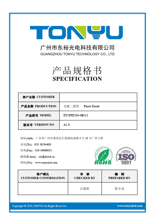
广州市东裕光电科技有限公司GUANGZHOU TONYU TECHNOLOGY CO., LTD产品规格书SPECIFICATION客户名称CUSTOMER产品名称PRODUCTION 光敏二极管Photo Diode 产品型号MODEL DY-FPD204-6B/L3版本号VERSION NO A1.0地址(Add):广东省广州市番禺区石基镇海涌路3号10号厂房2楼电话(Tel):************传真(Fax):************邮箱(E-mail):************网址(Net):客户确认CUSTOMER CONFIRMATION审核CHECKED BY编制PREPARED BY 汪建新陈少龙DY-FPD204-6B/L3产品描述Descriptions⚫DY-FPD204-6B/L3是一种NPN型高速度和高敏感的光敏二极管.(DY-FPD204-6B/L3 is an NPN type photosensitive transistor with high speed and high sensitivity.)产品特性Features⚫响应时间快(Fast response time)⚫高灵敏度(High photo sensitivity)⚫引脚间距2.54mm (2.54mm Lead spacing)⚫无铅(Pb free)⚫符合RoHS要求(This product itself will remain within RoHS compliant version)产品应用Applications⚫自动门传感器(Automatic door sensor.)⚫游戏机(Game machine)⚫高速光电探测器(High speed photo detector)包装方式Packing Quantity Specification⚫袋装:1000PCS/袋,4袋/小盒,10小盒/箱(1000PCS/1Bag,4Bags/1Box,10Boxes/1Carton)一、外形图Outline dimensions :单位 Unit公差 Tolerance芯片材料 Die material发光颜色 Emission color胶体颜色 Lens colormm±0.25mmSilicon- BlackNotes: 1. All dimensions are in mm, tolerance is ±0.25 unless otherwise noted.2. An epoxy meniscus way extend about 1.5mm down the leads.3. Burr around bottom of epoxy may be 0.5mm Max. ※备注:承认书之编号和型号可用于查询,客户如有需要,请提供相应的编号和型号。
MMSZ4xxxT1G系列和SZMMSZ4xxxT1G系列零点电阻电源器件的商品说明书

MMSZ4686T1G MMSZ4686T1G.MMSZ4xxxT1G Series, SZMMSZ4xxxT1G Series Zener Voltage Regulators 500 mW, Low I ZT SOD−123 Surface MountThree complete series of Zener diodes are offered in the convenient, surface mount plastic SOD−123 package. These devices provide a convenient alternative to the leadless 34−package style.Features•500 mW Rating on FR−4 or FR−5 Board•Wide Zener Reverse V oltage Range − 1.8 V to 43 V•Low Reverse Current (I ZT) − 50 m A•Package Designed for Optimal Automated Board Assembly •Small Package Size for High Density Applications•ESD Rating of Class 3 (>16 kV) per Human Body Model•SZ Prefix for Automotive and Other Applications Requiring Unique Site and Control Change Requirements; AEC−Q101 Qualified and PPAP Capable•These Devices are Pb−Free and are RoHS Compliant*Mechanical Characteristics:CASE:V oid-free, transfer-molded, thermosetting plastic case FINISH:Corrosion resistant finish, easily solderableMAXIMUM CASE TEMPERATURE FOR SOLDERING PURPOSES: 260°C for 10 SecondsPOLARITY:Cathode indicated by polarity band FLAMMABILITY RATING:UL 94 V−0MAXIMUM RATINGSRating Symbol Max Units Total Power Dissipation on FR−5 Board,(Note 1) @ T L = 75°CDerated above 75°C P D5006.7mWmW/°CThermal Resistance, (Note 2) Junction−to−Ambient R q JA340°C/WThermal Resistance, (Note 2) Junction−to−Lead R q JL150°C/WJunction and Storage Temperature Range T J, T stg−55 to+150°CStresses exceeding those listed in the Maximum Ratings table may damage the device. If any of these limits are exceeded, device functionality should not be assumed, damage may occur and reliability may be affected.1.FR−5 = 3.5 X 1.5 inches, using the minimum recommended footprint.2.Thermal Resistance measurement obtained via infrared Scan Method.*For additional information on our Pb−Free strategy and soldering details, please download the ON Semiconductor Soldering and Mounting Techniques Reference Manual, SOLDERRM/D.Cathode AnodeSee specific marking information in the device marking column of the Electrical Characteristics table on page 3 of this data sheet.DEVICE MARKING INFORMATIONSOD−123CASE 425STYLE 1Device Package Shipping†ORDERING INFORMATIONMARKING DIAGRAM†For information on tape and reel specifications, including part orientation and tape sizes, please refer to our T ape and Reel Packaging Specifications Brochure, BRD8011/D.MMSZ4xxxT1G SOD−123(Pb−Free)3,000 /Tape & ReelMMSZ4xxxT3G SOD−123(Pb−Free)10,000 /Tape & Reel xx= Device Code (Refer to page 3)M= Date CodeG= Pb−Free Package(Note: Microdot may be in either location)1SZMMSZ4xxxT1G SOD−123(Pb−Free)3,000 /Tape & ReelSZMMSZ4xxxT3G SOD−123(Pb−Free)10,000 /Tape & ReelELECTRICAL CHARACTERISTICS (T A = 25°C unless otherwise noted, V F = 0.9 V Max. @ I F = 10 mA)Symbol ParameterV Z Reverse Zener Voltage @ I ZTI ZT Reverse CurrentI R Reverse Leakage Current @ V RVR Reverse VoltageI F Forward CurrentV F Forward Voltage @ I FProduct parametric performance is indicated in the Electrical Characteristics for the listed test conditions, unless otherwise noted. Product performance may not be indicated by the Electrical Characteristics if operated under different conditions.ELECTRICAL CHARACTERISTICS (T A = 25°C unless otherwise noted, V F = 0.9 V Max. @ I F = 10 mA)Device*DeviceMarkingZener Voltage (Note 3)Leakage CurrentV Z (Volts)@ I ZT I R @ V RMin Nom Max m A m A VoltsMMSZ4678T1G CC 1.71 1.8 1.89507.51 MMSZ4679T1G CD 1.90 2.0 2.105051 MMSZ4680T1G CE 2.09 2.2 2.315041 MMSZ4681T1G CF 2.28 2.4 2.525021 MMSZ4682T1G CH 2.565 2.7 2.8355011 MMSZ4683T1G CJ 2.85 3.0 3.15500.81 MMSZ4684T1G CK 3.13 3.3 3.47507.5 1.5 MMSZ4685T1G CM 3.42 3.6 3.78507.52 MMSZ4686T1G CN 3.70 3.9 4.105052 MMSZ4687T1G CP 4.09 4.3 4.525042 SZMMSZ4687T1G CG6 4.09 4.3 4.525042 MMSZ4688T1G CT 4.47 4.7 4.9450103 MMSZ4689T1G CU 4.85 5.1 5.3650103 MMSZ4690T1G/T3G CV 5.32 5.6 5.8850104 MMSZ4691T1G CA 5.89 6.2 6.5150105 MMSZ4692T1G CX 6.46 6.87.145010 5.1 MMSZ4693T1G CY7.137.57.885010 5.7 MMSZ4694T1G CZ7.798.28.61501 6.2 MMSZ4695T1G DC8.278.79.14501 6.6 MMSZ4696T1G DD8.659.19.56501 6.9 MMSZ4697T1G DE9.501010.505017.6 MMSZ4698T1G DF10.451111.55500.058.4 MMSZ4699T1G DH11.401212.60500.059.1 MMSZ4700T1G DJ12.351313.65500.059.8 MMSZ4701T1G DK13.301414.70500.0510.6 MMSZ4702T1G DM14.251515.75500.0511.4 MMSZ4703T1G†DN15.201616.80500.0512.1 MMSZ4704T1G DP16.151717.85500.0512.9 MMSZ4705T1G DT17.101818.90500.0513.6 MMSZ4706T1G DU18.051919.95500.0514.4 MMSZ4707T1G DV19.002021.00500.0115.2 MMSZ4708T1G DA20.902223.10500.0116.7 MMSZ4709T1G DX22.802425.20500.0118.2 MMSZ4710T1G DY23.752526.25500.0119.0 MMSZ4711T1G†EA25.652728.35500.0120.4 MMSZ4712T1G EC26.602829.40500.0121.2 MMSZ4713T1G ED28.503031.50500.0122.8 MMSZ4714T1G EE31.353334.65500.0125.0 MMSZ4715T1G EF34.203637.80500.0127.3 MMSZ4716T1G EH37.053940.95500.0129.6 MMSZ4717T1G EJ40.854345.15500.0132.6 3.Nominal Zener voltage is measured with the device junction in thermal equilibrium at T L = 30°C ±1°C.*Include SZ-prefix devices where applicable.†MMSZ4703 and MMSZ4711 Not Available in 10,000/Tape & ReelTYPICAL CHARACTERISTICSV Z , T E M P E R A T U R E C O E F F I C I E N T (m V /C )°θV Z , NOMINAL ZENER VOLTAGE (V)Figure 1. Temperature Coefficients (Temperature Range −55°C to +150°C)V Z , T E M P E R A T U R E C O E F F I C I E N T (m V /C )°θ100101V Z , NOMINAL ZENER VOLTAGE (V)Figure 2. Temperature Coefficients (Temperature Range −55°C to +150°C)1.21.00.80.60.40.20T, TEMPERATURE (5C)Figure 3. Steady State Power Derating P p k, P E A K S U R G E P O W E R (W A T T S )PW, PULSE WIDTH (ms)Figure 4. Maximum Nonrepetitive Surge PowerP D , P O W E R D I S S I P A T I O N (W A T T S )V Z , NOMINAL ZENER VOLTAGEFigure 5. Effect of Zener Voltage onZener ImpedanceZ Z T , D Y N A M I C I M P E D A N C E ()ΩTYPICAL CHARACTERISTICSC , C A P A C I T A N C E (p F )V Z , NOMINAL ZENER VOLTAGE (V)Figure 6. Typical Capacitance 1000100101V Z , ZENER VOLTAGE (V)1001010.10.01I Z , Z EN E R C U R R E N T (m A )V Z , ZENER VOLTAGE (V)1001010.10.01I R , L E A K A G E C U R R E N T (A )μV Z , NOMINAL ZENER VOLTAGE (V)Figure 7. Typical Leakage Current10001001010.10.010.0010.00010.00001I Z , Z E N E R C U R R E N T (m A )Figure 8. Zener Voltage versus Zener Current(V Z Up to 12 V)Figure 9. Zener Voltage versus Zener Current(12 V to 91 V)SOD−123CASE 425−04ISSUE GDATE 07 OCT 2009SCALE 5:1NOTES:1.DIMENSIONING AND TOLERANCING PER ANSIY14.5M, 1982.2.CONTROLLING DIMENSION: INCH.DIM MIN NOM MAXMILLIMETERSINCHESA0.94 1.17 1.350.037A10.000.050.100.000b0.510.610.710.020c1.600.150.055D 1.40 1.80E 2.54 2.69 2.840.100---3.680.140L0.253.860.0100.0460.0020.0240.0630.1060.1450.0530.0040.0280.0710.1120.152MIN NOM MAX3.56H E---------0.006------------GENERICMARKING DIAGRAM**For additional information on our Pb−Free strategy and solderingdetails, please download the ON Semiconductor Soldering andMounting Techniques Reference Manual, SOLDERRM/D.SOLDERING FOOTPRINT**This information is generic. Please refer to device datasheet for actual part marking. Pb−Free indicator, “G” ormicrodot “ G”, may or may not be present.XXX= Specific Device CodeM= Date CodeG= Pb−Free Package1STYLE 1:PIN 1. CATHODE2. ANODE0.910.036ǒmminchesǓSCALE 10:1------q001010°°°°(Note: Microdot may be in either location) MECHANICAL CASE OUTLINEPACKAGE DIMENSIONSON Semiconductor and are trademarks of Semiconductor Components Industries, LLC dba ON Semiconductor or its subsidiaries in the United States and/or other countries.ON Semiconductor reserves the right to make changes without further notice to any products herein. ON Semiconductor makes no warranty, representation or guarantee regarding the suitability of its products for any particular purpose, nor does ON Semiconductor assume any liability arising out of the application or use of any product or circuit, and specifically disclaims any and all liability, including without limitation special, consequential or incidental damages. ON Semiconductor does not convey any license under its patent rights nor theON Semiconductor and are trademarks of Semiconductor Components Industries, LLC dba ON Semiconductor or its subsidiaries in the United States and/or other countries.ON Semiconductor owns the rights to a number of patents, trademarks, copyrights, trade secrets, and other intellectual property. A listing of ON Semiconductor’s product/patent coverage may be accessed at ON Semiconductor makes no warranty, representation or guarantee regarding the suitability of its products for any particular purpose, nor does ON Semiconductor assume any liability arising out of the application or use of any product or circuit, and specifically disclaims any and all liability, including without limitation special, consequential or incidental damages.PUBLICATION ORDERING INFORMATIONTECHNICAL SUPPORTNorth American Technical Support:Voice Mail: 1 800−282−9855 Toll Free USA/Canada Phone: 011 421 33 790 2910LITERATURE FULFILLMENT :Email Requests to:*******************ON Semiconductor Website: Europe, Middle East and Africa Technical Support:Phone: 00421 33 790 2910For additional information, please contact your local Sales RepresentativeMMSZ4686T1G MMSZ4686T1G.。
最全Proteus元件库元件名称及中英对照-51单片机仿真软件Proreus学习必用【范本模板】

Proteus元件库元件名称及中英对照AND 与门ANTENNA 天线BATTERY 直流电源BELL 铃,钟BVC 同轴电缆接插件BRIDEG 1 整流桥(二极管) BRIDEG 2 整流桥(集成块) BUFFER 缓冲器BUZZER 蜂鸣器CAP 电容CAPACITOR 电容CAPACITOR POL 有极性电容CAPVAR 可调电容CIRCUIT BREAKER 熔断丝COAX 同轴电缆CON 插口CRYSTAL 晶体整荡器DB 并行插口DIODE 二极管DIODE SCHOTTKY 稳压二极管DIODE VARACTOR 变容二极管DPY_3—SEG 3段LEDDPY_7-SEG 7段LEDDPY_7—SEG_DP 7段LED(带小数点)ELECTRO 电解电容FUSE 熔断器INDUCTOR 电感INDUCTOR IRON 带铁芯电感INDUCTOR3 可调电感JFET N N沟道场效应管JFET P P沟道场效应管LAMP 灯泡LAMP NEDN 起辉器LED 发光二极管METER 仪表MICROPHONE 麦克风MOSFET MOS管MOTOR AC 交流电机MOTOR SERVO 伺服电机NAND 与非门NOR 或非门NOT 非门NPN NPN三极管NPN-PHOTO 感光三极管OPAMP 运放OR 或门PHOTO 感光二极管PNP 三极管NPN DAR NPN三极管PNP DAR PNP三极管POT 滑线变阻器PELAY-DPDT 双刀双掷继电器RES1.2 电阻RES3.4 可变电阻RESISTOR BRIDGE ?桥式电阻RESPACK ?电阻SCR 晶闸管PLUG ?插头PLUG AC FEMALE 三相交流插头SOCKET ? 插座SOURCE CURRENT 电流源SOURCE VOLTAGE 电压源SPEAKER 扬声器SW ?开关SW-DPDY ?双刀双掷开关SW-SPST ? 单刀单掷开关SW-PB 按钮THERMISTOR 电热调节器TRANS1 变压器TRANS2 可调变压器TRIAC ?三端双向可控硅TRIODE ?三极真空管VARISTOR 变阻器ZENER ?齐纳二极管DPY_7—SEG_DP 数码管SW-PB 开关元件名称中文名说明7407 驱动门1N914 二极管74Ls00 与非门74LS04 非门74LS08 与门74LS390 TTL 双十进制计数器7SEG 4针BCD-LED 输出从0—9对应于4根线的BCD码7SEG 3-8译码器电路BCD—7SEG转换电路AlterNATOR 交流发电机AMMETER—MILLI mA安培计AND 与门BATTERY 电池/电池组BUS 总线CAP 电容CAPACITOR 电容器CLOCK 时钟信号源CRYSTAL 晶振Compim 串口D—FLIPFLOP D触发器FUSE 保险丝GROUND 地LAMP 灯LED—RED 红色发光二极管LM016L 2行16列液晶可显示2行16列英文字符,有8位数据总线D0-D7,RS,R/W,EN三个控制端口(共14线),工作电压为5V。
Agilent Power PLCC-4 SMT LED 产品说明书
HSMV-A400-U80M1DescriptionAgilent Power PLCC-4 is an extension of our PLCC-2 SMT LEDs. The package can be driven at higher current due to its superior package design. The product is able to dissipate heat more efficiently compared to the conventional PLCC-2 SMT LEDs.In proportion to the increase in driving current, this family of LEDs is able to produce higher light output compared to the conventional PLCC-2 SMT LEDs.These SMT LEDs have higher reliability and better performance and are designed to work under a wide range of environmentalconditions. This higher reliability makes them suitable for use under harsh environment and conditions like automotive. In addition, they are also suitable to be used in electronic signs and signals.Agilent HSMx-A4xx-xxxxx SMT LED Surface Mount LED IndicatorData SheetCAUTION: HSMN-, HSMK-, HSMM-A40x-xxxxx LEDs are Class 2 ESD sensitive. Please observe appropriate precautions during handling and processing. Refer to Agilent Application Note AN-1142 for additional details.To facilitate easy pick and place assembly, the LEDs are packed in EIA-compliant tape and reel.Every reel will be shipped in single intensity and color bin (except for red color), to provide close uniformity.These LEDs are compatible with IR solder reflow process. Due to the high reliability feature of these products, they also can be mounted using through-the-wave soldering process.There are a variety of colors and various viewing angles (30°, 60°and 120°) available in these SMT LEDs. Ideally, the 30° parts are suitable for light piping where focused intensities are required.As for the 60° and 120°, they are most suitable for automotive interior and exterior lighting and electronic signs applications.Features•Industry standard PLCC-4•High reliability LED package •High brightness using AlInGaP and InGaN dice technologies •High optical efficiency•Higher ambient temperature at the same current possible compared to PLCC-2•Available in full selection of colors•Super wide viewing angle at 120˚•Available in 8mm carrier tape on 7-inch reel •Compatible with both IR and TTW soldering process Applications•Interior automotive– Instrument panel backlighting – Central console backlighting – Cabin backlighting– Navigation and audio system – Dome lighting– Push button backlighting •Exterior automotive – Turn signals – CHMSL– Rear combination lamp – Puddle light•Electronic signs and signals – Interior full color sign – Variable message sign•Office automation, home appli-ances, industrial equipment – Front panel backlighting – Push button backlighting – Display backlightingPackage DimensionsNOTE: ALL DIMENSIONS IN mm.Device Selection GuideColor Part Number Min. I v (mcd)Max. I v (mcd)Test Current (mA)Dice Technology Red HSMC-A400-S30M1160.0400.050AlInGaP HSMC-A401-T40M1250.0800.050AlInGaPHSMC-A401-T80M1310.01000.050AlInGaPHSMZ-A400-U80M1500.01600.050AlInGaPRed Orange HSMJ-A401-T40M1250.0800.050AlInGaP HSMJ-A401-U40M1400.01260.050AlInGaPHSMV-A400-U80M1500.01600.050AlInGaP Orange HSML-A401-U40M1400.01260.050AlInGaP Amber HSMA-A400-T35M1250.0630.050AlInGaP HSMA-A401-U45M1400.01260.050AlInGaPHSMU-A400-U85M1500.01600.050AlInGaP Emerald Green HSME-A401-P4PM140.0130.050AlInGaPGreen HSMM-A401-R7YM2120.0320.030InGaN HSMM-A401-S4YM2160.0500.030InGaNHSMM-A401-S7YM2200.0500.030InGaNHSMM-A400-T8YM2310.01000.030InGaNCyan HSMK-A401-R40M2100.0320.030InGaN HSMK-A400-T80M2310.01000.030InGaNBlue HSMN-A401-P4QM240.0130.030InGaN HSMN-A401-P7QM250.0130.030InGaNHSMN-A400-Q8QM280.0250.030InGaNNote:1. The luminous intensity, I v, is measured at the mechanical axis of the lamp package. The actual peak of the spatial radiation pattern may not be aligned.Part Numbering SystemHSM x1 – A x2 x3x4 – x5x6 x7 x8x9Packaging OptionColor Bin SelectionIntensity Bin SelectDevice Specific ConfigurationPackage TypeLED Chip ColorAbsolute Maximum Ratings (T A = 25°C)Parameters HSMC/J/L/A/E HSMZ/V/U HSMM/K/N DC Forward Current[1]70 mA[3,4]70 mA[3,4]30 mA Peak Forward Current [2]200 mA200 mA90 mA Power Dissipation180 mW240 mW114 mW Reverse Voltage 5 VJunction Temperature 110°COperating Temperature –40°C to +100°CStorage Temperature –40°C to +100°CNotes:1.Derate linearly as shown in figure 5.2.Duty factor = 10%, Frequency = 1 kHz.3.Drive current between 10 mA and 70 mA is recommended for best long-term performance.4.Operation at currents below 5 mA is not recommended.Optical Characteristics (T A = 25°C)PeakDominant LuminousLuminous Intensity/Wavelength Wavelength Viewing Angle Efficacy ηv [3]Total FluxPart λPEAK (nm)λD [1] (nm)2θ1/2[2] (Degrees)(lm/W)I v (mcd)/Φv (mlm)Color Number Typ.Typ.Typ.Typ.Typ.Red HSMC 6356261201500.45HSMZ 6396301201550.45Red Orange HSMJ 6216151202400.45HSMV 6236171202630.45Orange HSML 6096051203200.45Amber HSMA 5925901204800.45HSMU 5945921205000.45Yellow Green HSME 5765751205600.45Emerald Green HSME 5685671206100.45Green HSMM 5185251205000.45Cyan HSMK 5025051203000.45BlueHSMN468470120750.45Notes:1.The dominant wavelength, λD , is derived from the CIE Chromaticity Diagram and represents the color of the device.2.θ1/2 is the off-axis angle where the luminous intensity is 1/2 the peak intensity.3.Radiant intensity, I e in watts/steradian, may be calculated from the equation I e = I v /ηv , where I v is the luminous intensity in candelas and ηv is the luminous efficacy in lumens/watt.Electrical Characteristics (T A = 25°C)Forward VoltageReverse VoltageV F (Volts) @ I F = 50 mA V R @ 100 µA Part Number Typ.Max.Min.HSMC/J/L/A/E 2.2 2.55HSMZ/V/U2.83.45Forward VoltageReverse Voltage V F (Volts) @ I F = 30 mA V R @ 10 µA Part Number Typ.Max.Min.HSMM/K/N3.84.65Figure 1. Relative Intensity Vs. Wavelength.WAVELENGTH – nmR E L A T I V E I N T E N S I T Y1.00.803804805806807307806305304300.60.40.20.10.30.50.70.9Figure 2. Forward Current Vs. Forward Voltage.Figure 3. Relative Intensity Vs. Forward Current (AlInGaP).Figure 4. Relative Intensity Vs. Forward Current (InGaN).Figure 5a. Maximum Forward Current Vs.Ambient Temperature, Derated Based On T J max = 110°C (AlInGaP).Figure 6. Dominant Wavelength Vs. Forward Current – InGaN Devices.Figure 7. Radiation Pattern.40FORWARD CURRENT – mA 00.4 R E L A T I V E I N T E N S I T Y (N O R M A L I Z E D A T 50 m A )800.80.21.0200.61.2601030701.450CURRENT – mAD O M I N A N T W A VE L E N G T H – n mR E L A T I V E I N T E N S I T Y1.00ANGLE – DEGREES0.80.60.20.4-70-50-3030507090-90-10100.10.30.50.70.9M A X I M U M F O R W A R D C U R R E N T – m AAMBIENT TEMPERATURE – °C0M A X I M U M F O R W A R D C U R R E N T – m AAMBIENT TEMPERATURE – °C 2030151035525Figure 5b. Maximum Forward Current Vs.Ambient Temperature, Derated Based On T J max = 110°C (InGaN).FORWARD VOLTAGE – V 0207080 F O R W A R D C U R R E N T – m A1050406030020FORWARD CURRENT – mA0.4 R E L A T I V E L U M I N O U S I N T E N S I T Y (N O R M A L I Z E D A T 30 m A )350.80.21.0100.61.23051525Figure 9a. Recommended SnPb Reflow Soldering Profile.Figure 10. Recommended Wave Soldering Profile.Figure 8a. Recommended Soldering Pad Pattern.TIMET E M P E R A T U R EFigure 8b. Recommended Soldering Pad Pattern (TTW).300°C/W >16 mm 2350°C/W >12 mm2470°C/W >8 mm 2Figure 9b. Recommended Pb-free Reflow Soldering Profile.* THE TIME FROM 25 °C TO PEAK TEMPERATURE = 6 MINUTES MAX.BOTTOM SIDE OF PC BOARD TIME – SECONDST E M P E R A T U R E – °CTOP SIDE OF PC BOARDCONVEYOR SPEED = 1.83 M/MIN (6 FT/MIN)PREHEAT SETTING = 150°C (100°C PCB)SOLDER WAVE TEMPERATURE = 245°C AIR KNIFE AIR TEMPERATURE = 390°C AIR KNIFE DISTANCE = 1.91 mm (0.25 IN.)AIR KNIFE ANGLE = 40°SOLDER: SN63; FLUX: RMANOTE: ALLOW FOR BOARDS TO BE SUFFICIENTL Y COOLED BEFORE EXERTING MECHANICAL FORCE.DIMENSIONS IN mm (INCHES).SOLDER RESISTDIMENSIONS IN mm (INCHES).Figure 11. Tape Leader and Trailer Dimensions.USER FEED DIRECTIONFigure 13. Reeling Orientation.Storage Condition: 5 to 30°C @60% relative humidity max.Baking is required under the condition:a) the humidity indicator card color becoming pinkb) the pack has been opened for more than 4 weeksBaking recommended condition:60 ± 5°C for 20 hours.0.1VIEW B-BIntensity Bin Select (X5X6) Individual reel will contain parts from one half bin only.X5Min. Iv BinX60Full Distribution3 3 half bins starting from X514 4 half bins starting from X515 5 half bins starting from X517 3 half bins starting from X528 4 half bins starting from X529 5 half bins starting from X52Intensity Bin LimitsBin ID Min. (mcd)Max. (mcd) N128.5035.50N235.5045.00P145.0056.00P256.0071.50Q171.5090.00Q290.00112.50R1112.50140.00R2140.00180.00S1180.00224.00S2224.00285.00T1285.00355.00T2355.00450.00U1450.00560.00U2560.00715.00V1715.00900.00V2900.001125.00W11125.001400.00W21400.001800.00 Tolerance of each bin limit = ± 12%Color Bin Select (X7)Individual reel will contain parts fromone full bin only.X70Full DistributionZ A and B onlyY B and C onlyW C and D onlyV D and E onlyU E and F onlyT F and G onlyS G and H onlyQ A, B and C onlyP B, C and D onlyN C, D and E onlyM D, E and F onlyL E, F and G onlyK F, G and H only1A, B, C and D only2E, F, G and H only3B, C, D and E only4C, D, E and F only5A, B, C, D and E only6B, C, D, E and F onlyColor Bin LimitsBlue Min. (nm)Max. (nm)A460.0465.0B465.0470.0C470.0475.0D475.0480.0Cyan Min. (nm)Max. (nm)A490.0495.0B495.0500.0C500.0505.0D505.0510.0Green Min. (nm)Max. (nm)A515.0520.0B520.0525.0C525.0530.0D530.0535.0Color Bin LimitsEmeraldGreen Min. (nm)Max. (nm)A552.5555.5B555.5558.5C558.5561.5D561.5564.5YellowGreen Min. (nm)Max. (nm)E564.5567.5F567.5570.5G570.5573.5H573.5576.5Amber/Yellow Min. (nm)Max. (nm)A582.0584.5B584.5587.0C587.0589.5D589.5592.0E592.0594.5F594.5597.0Orange Min. (nm)Max. (nm)A597.0600.0B600.0603.0C603.0606.0D606.0609.0E609.0612.0RedOrange Min. (nm)Max. (nm)A611.0616.0B616.0620.0Red Min. (nm)Max. (nm)Full DistributionTolerance of each bin limit = ± 1 nmPackaging Option (X8X9)Test Package ReelOption Current Type SizeM150 mA Top Mount7 inchM230 mA Top Mount7 inchForward Voltage Bin TableFor HSMZ/V/U – A4xx-xxxxx only BIN MIN.MAX.VA 1.9 2.2VB 2.2 2.5VC 2.5 2.8VD 2.8 3.1VE 3.1 3.4 Tolerance of each bin limit = ± 0.05/semiconductors For product information and a complete list of distributors, please go to our web site.For technical assistance call:Americas/Canada: +1 (800) 235-0312 or (916) 788-6763Europe: +49 (0) 6441 92460China: 10800 650 0017Hong Kong: (+65) 6756 2394India, Australia, New Zealand: (+65) 6755 1939 Japan: (+81 3) 3335-8152 (Domestic/Interna-tional), or 0120-61-1280 (Domestic Only) Korea: (+65) 6755 1989Singapore, Malaysia, Vietnam, Thailand, Philippines, Indonesia: (+65) 6755 2044 Taiwan: (+65) 6755 1843Data subject to change.Copyright © 2004 Agilent Technologies, Inc. Obsoletes 5989-0663ENOctober 12, 20045989-1211ENHSMV-A400-U80M1。
环形防喷器(D型)
使用说明书环形防喷器(D型)河北华北石油荣盛机械制造有限公司地址:河北省任丘市会战道目录1.用途 (2)2.产品规格及技术参数 (2)2.1.环形防喷器型号说明 (2)2.2.技术参数 (4)3.工作原理 (9)4.结构特点 (10)4.1.结构简单可靠 (10)4.2.耐磨圈结构 (10)4.3.唇形密封圈结构 (10)4.4.抗硫化氢性能 (11)4.5.球形胶芯 (11)5.操作与维护 (12)5.1.安装 (12)5.2.强行起下钻操作 (13)5.3.正确使用环形防喷器 (14)6.零部件拆装 (14)6.1.拆卸 (15)6.1.1.胶芯的更换 (15)6.1.2.支持圈与活塞拆卸: (15)6.2.装配 (15)7.FH54-35的零部件拆装 (16)8.橡胶件的存放 (17)9.故障判断及排除方法 (17)9.1.防喷器封闭渗漏 (17)9.2.防喷器关闭后打不开 (18)9.3.防喷器开关不灵活 (18)10.修理包明细 (18)11.定货说明 (20)1.用途环形防喷器必须配备液压控制系统才能使用。
通常它与闸板防喷器配套使用,但也可单独使用。
它能完成以下作业:●以密封各种形状和尺寸的方钻杆、钻杆、钻杆接头、钻铤、套管、电缆等工具;●当井内无钻具时,能全封闭井口;●在使用缓冲贮能器的情况下,能通过18°/35°无细扣对焊接头,进行强行起下钻作业。
●环形防喷器仅是在关井时的一个过渡设备,不能用它长时间的封井,长时间的封井应采用闸板防喷器;2.产品规格及技术参数2.1. 环形防喷器型号说明×××××——××额定工作压力(MPa)通径代号产品代号产品代号:FH—球形胶芯环形防喷器FHZ—锥形胶芯环形防喷器额定工作压力:主要有四个等级,见下表表 1 额定工作压力等级通径代号见下表:表 2 通径代号2.金属材料的温度等级:表 3 金属材料的温度等级3.接触井液的非金属密封件温度等级。
ISIS_7_Professional元件库列表及中英文对照合并版
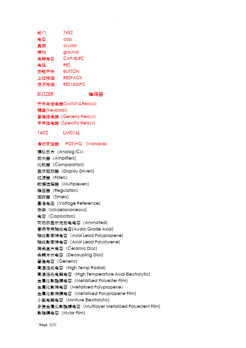
或门7432电容cap晶振crystal接地ground电解电容CAP-ELEC电阻RES按钮开关BUTTON上拉排阻RESPACK限流排阻RES16DIPISBUZZER 蜂鸣器开关与继电器(Switch&Relays)键盘(Keypads)普通继电器(Generic Relays)专用继电器(Specific Relays)1602 LM016L滑动变阻器POT-HG (Variable)模拟芯片(Analog ICs)放大器(Amplifiers)比较器(Comparators)显示驱动器(Display Drivers)过滤器(Filters)数据选择器(Multiplexers)稳压器(Regulators)定时器(Timers)基准电压(Voltage Reference)杂类(Miscellananeous)电容(Capacitors)可动态显示充放电电容(Animated)音响专用轴线电容(Audio Grade Axial)轴线聚苯烯电容(Axial Lead Polypropene)轴线聚苯烯电容(Axial Lead Polystyrene)陶瓷圆片电容(Ceramic Disc)去耦片状电容(Decoupling Disc)普通电容(Generic)高温径线电容(High Temp Radial)高温径线电解电容(High Temperature Axial Electrolytic)金属化聚酯膜电容(Metallised Polyester Film)金属化聚烯电容(Metallised Polypropene)金属化聚烯膜电容(Metallised Polypropene Film)小型电解电容(Miniture Electrolytic)多层金属化聚酯膜电容(Multilayer Metallised Polyestern Film) 聚脂膜电容(Mylar Film)镍栅电容(Nickel Barrier)无极性电容(Non Polarised)聚脂层电容(Polyester Layer)径线电解电容(Radial Electrolytic)树脂蚀刻电容(Resin Dipped)钽珠电容(Tantalum Bead)可变电容(Variable)VX轴线电解电容(VX Axial Electolytic) 连接器(Connectors)音频接口(Audio)D 型接口(D-Type)双排插座(DIL)插头(Header Blocks)PCB转接器(PCB Transfer)带线(Ribbon Cable)单排插座(SIL)连线端子(Terminal Blocks)杂类(Miscellananeous)数据转换器(Data Converter)模/数转换器(A/D converters)数/模转换器(D/A converters)采样保持器(Sample & Hold)温度传感器(Temperature Sensore)调试工具(Debugging Tools)断点触发器(Breakpoint Triggers)逻辑探针(Logic Probes)逻辑激励源(Logic Stimuli)二极管(Diode)整流桥(Bridge Rectifiers)普通二极管(Generic)整流管(Rectifiers)肖特基二极管(Schottky)开关管(Switching)隧道二极管(Tunnel)变容二极管(Varicap)齐纳击穿二极管(Zener)ECL 10000系列(ECL 10000 Series)各种常用集成电路机电(Electromechanical)各种直流和步进电机电感(Inductors)普通电感(Generic)贴片式电感(SMT Inductors)变压器(Transformers)拉普拉斯变换(Laplace Primitives)一阶模型(1st Order)二阶模型(2st Order)控制器(Controllers)非线性模式(Non-Linear)算子(Operators)极点/零点(Poles/Zones)符号(Symbols)存储芯片(Memory Ics)动态数据存储器(Dynamic RAM)电可擦除可编程存储器(EEPROM)可擦除可编程存储器(EPROM)I2C总线存储器(I2C Memories)SPI总线存储器(SPI Memories)存储卡(Memory Cards)静态数据存储器(Static Memories)微处理器芯片(Microprocess ICs)6800 系列(6800 Family)8051 系列(8051 Family)ARM 系列(ARM Family)AVR 系列(AVR Family)Parallax 公司微处理器(BASIC Stamp Modules)HCF11 系列(HCF11 Family)PIC10 系列(PIC10 Family)PIC12 系列(PIC12 Family)PIC16 系列(PIC16 Family)PIC18 系列(PIC18 Family)Z80系列(Z80 Family)CPU 外设(Peripherals)杂项(Miscellaneous)含天线、ATA/IDE硬盘驱动模型、单节与多节电池、串行物理接口模型、晶振、动态与通用保险、模拟电压与流符号、交通信号灯建模源(Modelling Primitives)模拟(仿真分析)(Analogy-SPICE)数字(缓冲器与门电路)(Digital--Buffers&Gates)数字(杂类)(Digital--Miscellaneous)数字(组合电路)(Digital--Combinational)数字(时序电路)(Digital--Sequential)混合模式(Mixed Mode)可编程逻辑器件单元(PLD Elements)实时激励源(Realtime Actuators)实时指示器(Realtime Indictors)运算放大器(Operational Amplifiers)单路运放(Single)二路运放(Dual)三路运放(Triple)四路运放(Quad)八路运放(Octal)理想运放(Ideal)大量使用的运放(Macromodel)光电子类器件(Optoelectronics)七段数码管(7-Segment Displays)英文字符与数字符号液晶显示器(Alphanumeric LCDs) 条形显示器(Bargraph Displays)点阵显示屏(Dot Matrix Display)图形液晶(Grphical LCDs)灯泡(Lamp)液晶控制器(LCD Controllers)液晶面板显示(LCD Panels Displays)发光二极管(LEDs)光耦元件(Optocouplers)串行液晶(Serial LCDs)可编程逻辑电路与现场可编程门阵列(PLD&FPGA)无子类电阻(Resistors)0.6W金属膜电阻(0.6W Metal Film)10W 绕线电阻(10W Wirewound)2W 金属膜电阻(2W Metal Film)3W 金属膜电阻(3W Metal Film)7W 金属膜电阻(7W Metal Film)通用电阻符号(Generic)高压电阻(High Voltage)负温度系数热敏电阻(NTC)排阻(Resisters Packs)滑动变阻器(Variable)可变电阻(Varistors)仿真源(Simulator Primitives)触发器(Flip-Flop)门电路(Gates)电源(Sources)扬声器与音响设备(Speaker&Sounders)无子分类开关与继电器(Switch&Relays)键盘(Keypads)普通继电器(Generic Relays)专用继电器(Specific Relays)按键与拨码(Switchs)开关器件(Switching Devices)双端交流开关元件(DIACs)普通开关元件(Generic)可控硅(SCRs)三端可控硅(TRIACs)热阴极电子管(Thermionic Valves)二极真空管(Diodes)三极真空管(Triodes)四极真空管(Tetrodes)五极真空管(Pentodes)转换器(Transducers)压力传感器(Pressures)温度传感器(Temperature)晶体管(Transistors)双极性晶体管(Bipolar)普通晶体管(Generic)绝缘栅场效应管(IGBY/Insulated Gate Bipolar Transistors 结型场效应晶体管(JFET)金属-氧化物半导体场效应晶体管(MOSFET)射频功率LDMOS晶体管(RF Power LDMOS)射频功率VDMOS晶体管(RF Power VDMOS)单结晶体管(Unijunction)CMOS 4000系列(CMOS 4000 seriesTTL 74系列(TTL 74 series)TTL 74增强型低功耗肖特基系列(TTL 74ALS Series)TTL 74增强型肖特基系列(TTL 74AS Series)TTL 74高速系列(TTL 74F Series)TTL 74HC系列/CMOS工作电平(TTL 74HC Series)TTL 74HCT系列/TTL工作电平(TTL 74HCT Series)TTL 74低功耗肖特基系列(TTL 74LS Series)TTL 74肖特基系列(TTL 74S Series)加法器(Adders)缓冲器/驱动器(Buffers&Drivers)比较器(Comparators)计数器(Counters)解码器(Decoders)编码器(Encoders)存储器(Memory)触发器/锁存器(Flip-Flop&Latches)分频器/定时器(Frequency Dividers & Timers)门电路/反相器(Gates&Inverters)数据选择器(Multiplexers)多谐振荡器(Multivibrators)振荡器(Oscillators)锁相环(Phrase-Locked-Loop,PLL) 寄存器(Registers)信号开关(Signal Switches)收发器(Tranxceivers)杂类逻辑芯片(Misc.Logic)Proteus isis 的元件库中英对照Proteus 元件名称对照1元件名称中文名说明7407 驱动门1N914 二极管74Ls00 与非门74LS04 非门74LS08 与门74LS390 TTL 双十进制计数器7SEG 4针BCD-LED 输出从0-9 对应于4根线的BCD码7SEG 3-8译码器电路BCD-7SEG[size=+0]转换电路ALTERNATOR 交流发电机AMMETER-MILLI mA安培计AND 与门BATTERY 电池/电池组BUS 总线CAP 电容CAPACITOR 电容器CLOCK 时钟信号源CRYSTAL 晶振D-FLIPFLOP D触发器FUSE 保险丝GROUND 地LAMP 灯LED-RED 红色发光二极管LM016L 2行16列液晶可显示2行16列英文字符,有8位数据总线D0-D7,RS,R/W,EN三个控制端口(共14线),工作电压为5V。
磁性开关SMC

磁 D-A7□H/A80H型
性 D-A73C/A80C型
开 D-A79W型
关 D-A5/A6型
D-A59W型
D-A9型
D-A9□V型
D-E7□A/E80A型
D-Z7/Z8型
D-P7型
D-B3型
执行元件页码索引 (圆型数字为Best No.。)
4P.1055 4P.1076 4P.1080 4P.1089 4P.1095 4P.1170 4P.1187 4P.1211 4P.1327 4P.1355 4P.1389 4P.1443 4P.1469 4P.1495 4P.1507 4P.1525 4P.1545 )P.15 )P.33 )P.35 )P.35 )P.165 )P.181 )P.205
ø4 ø6·ø10·ø16 ø10·ø16 ø6 ø10·ø16 ø20~ø40 ø20~ø40 ø20~ø40 ø20~ø63 ø80·ø100 ø20~ø63 ø80·ø100 ø20~ø63 ø80·ø100 ø32~ø100 ø32~ø125 ø40~ø100 ø32~ø125 ø40~ø100 ø40~ø100 ø40~ø100 ø125~ø200 ø125~ø160 ø6~ø20 ø6~ø32 ø12~ø20 ø25 ø12~ø25 ø32~ø100 ø125~ø160 ø180~ø200 ø16~ø63 ø20·ø25 ø32~ø50 ø12~ø25 ø32~ø100 ø20~ø40 ø25~ø63
点 磁 性 开 关
D-F5BA型 D-F5□W/J59W型 D-F59F型 D-F5NT型
D-G39C/K39C型
D-M9型
D-M9□V型
D-M9□W型
D-M9□WV型
D-M9□A型
朗诚电子有限公司 一系列的通用服务电子阀门说明书

% ^ # )Features• Welded core tube provides higher pressure ratings •Reliable, proven design with high flows •Small poppet valves for tight shutoff•Wide range of elastomers for specialty service applications•Mountable in any position• T apped mounting holes in body standardSolenoid EnclosuresNominal Ambient T emp. RangesThe nominal limitation of 32°F (0°C) is advisable for any valve that might contain moisture (water vapor). AC: -13˚F to 131˚F (-25˚C to 55˚C)DC: -13˚F to 104˚F (-25˚C to 40˚C)-13˚F to 131˚F (-25˚C to 55˚C)Note: Max ambient for explosionproof (EF) is 125˚F (52˚C) for AC, 131˚F (55˚C) for DC.Optional: For AC, the max. ambient temperature is140˚F (60˚C) with Class H coil (with or without prefix EF)Refer to Engineering Section for details.ApprovalsCSA certified. UL listed, as indicated. Safety Shutoff Valves FM approved. Meets applicable CE directives.Refer to Engineering Section for details.Standard:Watertight, Types 1, 2, 3, 3S, 4, and 4X.Optional:Explosionproof and Watertight, Types 3, 3S, 4, 4X, 6, 6P , 7, and 9.(To order, add prefix “EF” to catalog number)See Optional Features Section for other available options.431OptionsMounting bracket (suffix MB)Quarter-turn manual operator with screw slot (suffix MS)Panel mount (prefix GP for conduit; consult ASCO for other electrical connections )Vacuum service (suffix VVM, VVH; see Vacuum Section for more details.)Oxygen service (suffix N)Silicone Free (suffix SF)Elastomers:Viton (suffix V), Ethylene Propylene (suffix E), Neoprene (suffix J), Teflon (suffix T), Low Temp NBR (suffix A)Note: For suffix A, Fluid temp. range -40˚F to 167˚F only for valves with 10.1, 17.1, 11.6, and 22.6 watt coils.Refer to Engineering Section for fluid and temperature compatibility.Specifications (English units)x Cast UR disc supplied as standard, limits min. ambient temp. to 32˚F (0˚C); G = General Purpose Valve, H= Safety Shutoff Valvex Cast UR disc supplied as standard, limits min. ambient temp. to 32˚F (0˚C); G = General Purpose Valve, H= Safety Shutoff ValveDimensions: inches (mm)34。
- 1、下载文档前请自行甄别文档内容的完整性,平台不提供额外的编辑、内容补充、找答案等附加服务。
- 2、"仅部分预览"的文档,不可在线预览部分如存在完整性等问题,可反馈申请退款(可完整预览的文档不适用该条件!)。
- 3、如文档侵犯您的权益,请联系客服反馈,我们会尽快为您处理(人工客服工作时间:9:00-18:30)。
DC-8.0 GHz InGaP HBT , MMIC or Packaged,Page 1 of 7CGB7014-SC (-BD)Features18.5 dB Gain @ 6 GHz24.5 dB Gain @ 850 MHz36.0 dBm Output IP3 @ 850 MHz 3.5 dB Noise Figure @ 850 MHz 20.3 dBm P1dB @ 850 MHzLow Performance Variation Over Temperature Low Cost: Die Form or SOT-89 Package 100% DC On-Wafer TestingESD Protection on All Die: >1000V HBM Low Thermal Resistance: <80ºC/WattPA Driver Amp, IF Amp, LO Buffer Amp Cellular, PCS, GSM, UMTS Wireless Data and SATCOM WLAN 802.11a/b/g and WiMAX Transmit and Receive Functions CATVApplicationsElectrical CharacteristicsUnless otherwise specified, the following specifications are guaranteed at room temperature in a Mimix test fixture.Notes: 1. Test Conditions in Mimix eval board, Vs = 8 V, Id = 80 mA Typ., Rbias = 39 , Zs = Zl = 50, OIP3 tone spacing = 1 MHz, Pout per tone = 6 dBm.2. Values reflect performance in recommended application circuit.850 MHz 1950 MHz2400 MHz3500 MHz6000 MHzUnitsMax.Typ.Min.Max.Typ.Min.Max.Typ.Min.Max.Typ.Min.Temperature (ºC)ParameterSmall Signal Gain Output P1dB Output IP3Noise Figure Operating Current Input Return Loss Output Return Loss Pout @ -45 dBc, ACPIS-95, 9 Forward Channels +25-40 to +85+25-40 to +85+25-40 to +85+25-40 to +85+25-40 to +85+25-40 to +85+25-40 to +85+25-40 to +8523.523.219.319.034.534.07672989824.524.520.320.336.036.03.53.580801212131313.513.525.525.84.34.7858922.021.718.017.730.029.076721312121123.023.019.019.031.531.53.53.580801919171713.513.524.024.34.34.7858921.521.217.116.828.527.576721211111022.522.518.118.130.030.03.63.680801818161623.523.84.65.0858921.521.516.016.027.027.03.83.8808014141717dB dB dBm dBm dBm dBm dB dB mA mA dB dB dB dB dBm dBmMax.Typ.Min.18.518.510.010.019.019.04.54.58080991818Max Device Voltage Max Device CurrentMax Device Dissipated Power RF Input PowerStorage Temperature Junction Temperature Operating Temperature Thermal Resistance EDS (HBM)+6.0 V 130 mA 0.65 W +17 dBm -55ºC to 150ºC 150ºC -40ºC to +85ºC 80º C/W 1000 VAbsolute Maximum RatingsDescriptionThe CGB7014-SC (-BD) is a Darlington Configured, high dynamic range, utility gain block amplifier. Designed for applications operating within the DC to 8.0 GHz frequency range, Mimix’s broadband, cascadable, gain block amplifiers are ideal solutions for transmit, receive and IF applications. These MMIC amplifiers are available in bare die form or an industry standard SOT-89 package. Mimix's InGaP HBT technology and an industry low thermal resistance offers a thermally robust and reliable gain block solution. The InGaP HBT die have extra pads to enable thorough DC testing. This unique test capability and the inclusion of ESD protection on all die, significantly enhances the quality, reliability and ruggedness of these products. With a single bypass capacitor, optional RF choke and two DC blocking capacitors, this gain block amplifier offers significant ease of use in a broad range of applications.Operation of this device above any of these parameters may cause permanent damage.May 2006 - Rev 23-May-06May 2006 - Rev 23-May-06Page 2 of 7DC-8.0 GHz InGaP HBT , MMIC or Packaged,CGB7014-SC (-BD)May 2006 - Rev 23-May-06Page 3 of 7T ypical Power and Linearity PerformanceDC-8.0 GHz InGaP HBT , MMIC or Packaged,CGB7014-SC (-BD)Linearity Performance - Base Station ACP – IS-95May 2006 - Rev 23-May-06Page 4 of 7T ypical Scattering Parameters (Vd = +4.75V, Icc = 77 mA, T = 23°C, device in a 50 ohm system)DC-8.0 GHz InGaP HBT , MMIC or Packaged,CGB7014-SC (-BD)Frequency S 11S 21S 12S 22(MHz)(Mag)(Ang)(Mag)(Ang)(Mag)(Ang)(Mag)(Ang)1000.2617917.91750.05-10.06-1742000.2617817.91690.05-30.06-1643000.2517617.81640.05-40.06-1594000.2617417.81590.05-50.07-1585000.2517417.61540.05-70.08-1546000.2517017.51480.05-80.08-1547000.2516917.41430.05-90.09-1558000.2416717.21380.05-110.09-1529000.2416617.11330.05-120.10-15410000.2416716.91280.05-140.11-15211000.2316316.71220.05-150.11-15512000.2316216.71170.05-160.12-15813000.2216416.31130.06-180.13-15614000.2116116.11070.06-190.13-15715000.2116216.01030.06-210.14-16116000.2116015.7970.06-220.14-16217000.2016015.5930.06-240.15-16318000.1916015.3880.06-250.15-16419000.1916015.1830.06-270.16-16720000.1916214.8780.06-290.16-16921000.1816114.6730.06-300.16-17022000.1716114.4680.06-320.16-17223000.1816314.1640.06-340.17-17424000.1716713.8600.06-350.18-17525000.1716513.6550.06-370.17-17626000.1816613.4510.06-390.18-17927000.1816913.1470.06-410.19-18028000.1716713.0420.06-420.1817929000.1816712.9380.06-440.1917630000.1816712.7330.06-460.1917431000.1916912.5290.07-480.2017332000.1816812.3250.07-500.2017233000.1916512.2210.07-520.2016934000.1916712.0160.07-540.2116635000.1916511.9110.07-560.2116636000.2016411.780.07-580.2116337000.2016511.530.07-600.2216138000.2016311.4-10.07-620.2315839000.2116111.2-50.07-640.2315540000.2115911.1-100.07-660.2315341000.2215910.9-140.07-690.2314942000.2115510.8-180.08-710.2414843000.2115110.7-220.08-730.2414444000.2215010.6-260.08-750.2414045000.2214710.5-310.08-780.2513746000.2214310.4-350.08-800.2413447000.2214010.2-390.08-820.2513048000.2213710.1-440.08-850.2612749000.2113210.1-480.08-870.2612350000.2112710-520.08-890.25118Continues Next Page.S-Parameter Data Files are available on-line at: May 2006 - Rev 23-May-06Page 5 of 7T ypical Scattering Parameters (Vd = +4.75V, Icc = 77 mA, T = 23°C, device in a 50 ohm system)DC-8.0 GHz InGaP HBT , MMIC or Packaged,CGB7014-SC (-BD)Frequency S 11S 21S 12S 22(MHz)(Mag)(Ang)(Mag)(Ang)(Mag)(Ang)(Mag)(Ang)51000.211259.8-570.08-920.2511452000.201219.7-610.09-950.2611153000.201159.6-650.09-980.2710754000.201099.6-700.09-1000.2710255000.201049.5-740.09-1030.279656000.19979.4-790.09-1060.279257000.20899.3-830.09-1090.278758000.20839.2-880.09-1130.288059000.19739.2-920.09-1160.297560000.20649.1-970.09-1190.296861000.20559.0-1020.10-1220.296262000.20469.0-1070.10-1250.305563000.20358.9-1120.10-1290.304964000.22248.8-1170.10-1320.304265000.23188.7-1220.10-1360.313466000.2468.6-1270.10-1400.322767000.26-28.5-1320.10-1430.322068000.27-108.3-1370.10-1470.331369000.29-188.2-1430.10-1510.34670000.31-268.0-1480.10-1550.35-271000.34-347.9-1530.10-1590.36-972000.37-407.7-1590.10-1630.37-1773000.39-497.5-1640.10-1670.38-2474000.42-557.3-1690.10-1710.39-3175000.44-617.1-1750.10-1750.40-3976000.46-68 6.91800.10-1790.41-4577000.49-73 6.71740.101770.42-5278000.51-79 6.51690.091740.43-5979000.53-84 6.21640.091700.44-6580000.55-90 6.01590.091660.45-7181000.57-95 5.71540.091620.46-7782000.60-99 5.51490.091590.47-8383000.61-105 5.31440.081550.48-8984000.63-110 5.11390.081510.48-9485000.64-114 4.81340.081480.49-9986000.65-118 4.61300.081450.50-10487000.67-123 4.41250.081410.51-10988000.68-127 4.21210.071380.51-11489000.69-131 4.01160.071350.51-11890000.69-135 3.81120.071330.52-12391000.70-139 3.61080.071300.52-12792000.71-142 3.51040.071270.52-13193000.71-146 3.31000.071240.53-13594000.72-150 3.1950.061210.53-13995000.72-153 3.0920.061180.53-14296000.72-156 2.8880.061160.53-14697000.72-160 2.7840.061130.53-14998000.73-163 2.6810.061110.54-15299000.73-166 2.5770.061090.54-155100000.73-169 2.4730.051070.54-159S-Parameter Data Files are available on-line at: May 2006 - Rev 23-May-06Page 6 of 7Application CircuitRF INVs RF OUTNote: This schematic represents the topology of the application circuit recommended by Mimix.R Bias = (Vs - Vd) / IdVdNote: Rbias provides DC bias stability over temperature.DC-8.0 GHz InGaP HBT , MMIC or Packaged,CGB7014-SC (-BD)May 2006 - Rev 23-May-06Page 7 of 7Physical Dimensions - SC Package (SOT -89)DC-8.0 GHz InGaP HBT , MMIC or Packaged,CGB7014-SC (-BD)Physical Dimensions - BD (Bare Die)Ordering InformationPart Number for Ordering DescriptionCGB7014-BD Bare die in GelPakCGB7014-SC-0G00 Matte Tin plated RoHS compliant SOT-89 surface mount package in bulk quantity CGB7014-SC-0G0T Matte Tin plated RoHS compliant SOT-89 surface mount package in tape and reel CGB7014-SP-0G00 Matte Tin plated RoHS compliant SOT-86 surface mount package in bulk quantity CGB7014-SP-0G0T Matte Tin plated RoHS compliant SOT-86 surface mount package in tape and reel PB-CGB7014-SC-0000 Evaluation Board for SOT-89 packaged device with SMA connectors PB-CGB7014-SP-0000Evaluation Board for SOT-86 packaged device with SMA connectorsWe also offer the plastic packages with SnPb (Tin-Lead) or NiPdAu plating. Please contact your regional sales manager for more information regarding different plating types。
