电子电气宝贝天地专区_en
ST-862D 热气枪工作站用户手册说明书

ST-862D Hot Air Station User Manual CBN031661(A)7. Restore F actory SettingIn FAC menu ,press “▲”and “▼”keys to adjust ON /OFF. Press the [2] key when the menu is ON, then return to the normal operation interface to restore factory settingLoc ( temperature locked function):OFFCAL (calibration value): cleared BL (Beeping function):ON F-C(temperature unit ):℃HTO (Timing operation) : OFFDefault value :FIG. 1-16FIG. 1-17Memory temperature 1:200°C Memory temperature2:300°C Memory temperature3:400°CCare And MaintenanceShortcut Key 1/Menu Key/Temp Plus KeyPower Key InterfaceSchematic Diagram of the Whole EquipmentConnection Diagram for the Whole Equipment5. Temperature CalibrationUnder menu CAL mode, press “▲”or“▼”key to enable temperature calibrationfunction, whose calibration range is -50℃~ 50℃(-90℉~90℉). Calibration value will be negative as actual-measured temperature is lower than setting temperature; Calibration value will be positive as actual-measured temperature is higher than setting temperature.FIG. 1-12FIG. 1-136. Button Beeping FunctionUnder menu BL mode, user can turn on/ off the beeping function by pressing “▲”or “▼”key.Refer Pic.1-14, OFF disable beeping function;Refer Pic.1-15, ON enables beeping function.FIG. 1-14FIG. 1-154. Switching Temperature UnitFIG. 1-10FIG. 1-11Shortcut Key 1/Menu Key/Note: User need calibrate temperature by adjusting its value if the displayed temperature is much different withactual-measured temperature after changing a new heater or tips, its calibration method be refered as below:1.Set this handle required calibration as a suitable temperature like 350℃/ 662℉;2.After this setting temperature is stable, use temperature tester to measure the actual temperature of its tip,for example, its actual-measured temperature is 365℃/ 689℉;3.We can get conclusion that the actual-measured temperature compared to the setting temperature is15℃/ 27℉ higher;4.Then press “▲” key to calibrate temperature.Menu ModeEnter into menu mode by pressing both Button “1” and “3” more than 3 secondsunder working status.FIG. 1-71. Button Definition under Menu Setting ModeButton “1”: Menu page upButton “2”: Menu exitButton “3”: Menu page downParameter plusParameter minus3. Defining Work FunctionUnder menu HTO mode, it can adjust time of defining work by pressing “▲”or“▼”key (FIG. 1-9, the time of defining work is 20 seconds, “0” means turn off defining workfunction, the minimum setting time for defining work is 10 seconds, maximum settingtime is 900 seconds. ); it can turn up or down menu by pressing Button “1” or “3”,then press Button “2” to exit and save your setting.FIG. 1-8FIG. 1-9Saving and Retrieving Shortcut Temperature(User define)1. Retrieving shortcut temperature: It can rapidly retrieving preset temperature and blowingrestored in Button “1”/“2”/“3” by pressing Button “1”/“2”/“3”.(FIG. 1-6)when working2. Saving shortcut temperature: It can save the user-define temperature and blowing inButton “1”/ “2”/ “3” by pressing Button “1”/ “2”/ “3” more than 3 seconds.FIG. 1-62. Temperature Locking FunctionUnder Menu Loc, it can turn on or turn off temperature locking function by pressing“▲”or“▼”key(FIG. 1-8, ON means turn on temperature lock function, OFF meansturn off temperature locking function); it can turn up or down menu by pressing Button“1” or “3”, then press Button “2” to exit and save your setting.Technical DataBoot-up ScreenAfter the station has been switched on, the display will turn on and show the system versionnumber for one second before switching to the normal display.(Means ST-862D V0.1 version)1. REAL (Real Temperature): Real Temperature status2. SET (Set Temperature): Start up and set temperature status3. Actual temperature value4. Display bar for heating power status5. Symbol for lock6. Display settings value7. Air flow percentage8. Temperature unitLCD DescriptionSettings1. Normal display(FIG. 1-1) shows real temperature is 300°C, the temperature setting value is locked, the air volume is 50% and the heating power value is 3 bars.FIG. 1-1Temperature/Air Flow Setting1. Adjust the air volume: Press air “▲” or “▼” key (see FIG 1-4). Long press for quickly adjusting. Stop pressing the key for 3 seconds, it will save the setting automatically.2. Adjust temperature value (when temperature value is locked, it can not be adjusted): Press temperature "▲" or "▼" key, switch to SET status (see figure 1-5). Long press for quickly adjusting, stop pressing the key for 3 seconds, it will automatically save temperature setting, and state switch to REAL.FIG. 1-4FIG. 1-52. Display Of Hot Air Gun Status(FIG. 1-2)shows when the air gun is off (non-power)) The setting value can be adjustedwhen the hot air gun is off. When the hot air gun is on, it will work according to the setting value.(FIG. 1-3) When the handle of the air gun is placed on the holder, the hot air gun will automatically stop heating and delay air supply, (the air supply will stop after the heating wire cools). Pick up the handle again and press the switch key on the handle, it will resume to work.FIG. 1-2FIG. 1-3。
智能电子设备(IED)轨迹管理手册说明书
As part of their Smart Grid initiatives, utilities have been deploying large numbers of Intelligent Electronic Devices (IEDs) to implement advanced automation systems. However, they are discovering the high cost of maintaining these devices. Originally considered as essentially capital intensive, projects in the electrical sector have seen increasing operational costs as utilities are faced with devices that require complex commissioning as well as regular firmware updates and security patches.In the same manner, as operators of large vehicle fleets have implemented “Fleet Management” programs supported by advanced software, utilities must now look for automated solutions to manage their IED fleets in order to tackle the ever increasing operational expenses.In this paper, we will discuss some of the basic functions required for managing large fleets of IEDs, the solutions that have been developedto help utilities meet North American Electric Reliability Corporation Critical Infrastructure Protection (NERC CIP) cybersecurity requirements, and how these solutions can also be applied to help utilities manage the IEDs being deployed in distribution automation systems.ContentsAdapting to today’s technology (2)Managing the device lifecycle (2)Managing devices inside the fence (2)Managing devices outside the fence (3)Summary (4)Conclusion (6)Managing intelligent electronic devices2White Paper WP913001ENEffective March 2016Managing intelligent electronic devicesEATON Adapting to today’s technologyPower distribution systems, which are essentially static, are increasingly becoming “active” and perform advancedcoordinated real-time functions such as Fault Location Isolation and Service Restoration (FLISR), real-time power network status reporting, VAR Management and Voltage Optimization and Control. While this technological evolution leads to valuable benefits, it also brings important new operational challenges. Advanced automation systems are built out of large numbers of programmable electronic devices, coming from a variety of vendors. All of these devices are expected to interoperate and exchange data in a secure and reliable manner.However, there has been a significant change in paradigm. Traditional OT (Operational Technology) systems were designed to be long lasting and made of simple technology, using simpleprotocols, with little or no security. Once operational, they were not expected to change.On the contrary, modern automation systems are increasinglyinheriting some of the characteristics of IT (Information Technology) systems:•The systems are becoming much more dynamic with a much shorter life expectancy•The devices are more complex and the firmware must be updated regularly in order to address:• security vulnerabilities• programming errors •simply to add new functions•Devices need to be replaced as their components rapidly become obsolete and are no longer manufactured•Each new generation of devices seems to implement new technologies and protocolsChange has thus become a fundamental characteristic of modern automation systems and must now be taken into account.The true benefits of modern automation systems will only be achieved if the cost of managing devices can be brought under control.Managing the device lifecycleLarge organizations have developed a significant body of knowledge, standards, and best practices in the management of largenumbers of networked devices used for their business operations. Implementing and maintaining large business networks requires a team of IT specialists that use specialized asset management tools such as Network M anagement Systems to assist in their tasks. In many cases, all the networking technology and tools will be selected from a single vendor to ensure seamless integration and complete control of the device lifecycle, from the initialcommissioning to its secure disposal. Modern devices can often obtain their configuration settings automatically from the Network Management System and become operational as soon as they are plugged in.This approach is very different from the evolutionary path that automation systems have been following. Communications, interoperability, and security have generally been secondary considerations as engineers selected “best of breed” devices, from a variety of vendors, according to their functional capabilities. Commissioning a device requires numerous manual operations, often using a proprietary software tool connected to a serial maintenance port. Up until now, this was not an issue since the automation system was often deployed as part of a largerproject, with very little changes expected or planned once it is commissioned.But, the reality of new devices is such that these systems areno longer static and need to be maintained, devices updated, or simply replaced. As utilities extend their communication networks to integrate ever-increasing numbers of devices in new applications, it will no longer be cost-effective to manage the system manually and some form of automatic configuration is inevitable.While vendors of networking devices and proponents of the Internet of Things (IoT) have been promoting a vision of plug-and-play devices and zero-touch deployment, the whole process of commissioning electrical controls such as protection relays, voltage regulators, recloser controls, and capacitor bank controls, from a variety of vendors, is much more complex and will remain so for the foreseeable future.While there are efforts to extend standards such as DNP3 and IEC 61850 to include device properties and configuration settings, these have not yet been widely adopted by the industry. The task of managing devices used in automation systems thus requires specialized knowledge and experience that can only be expected from vendors in the electrical sector. Fortunately, as we will see in the next section, such applications are already available.Managing devices inside the fenceThe electrical substation is the host of a large number of IEDs, from a variety of vendors, used for protection, metering, monitoring, and communications. Utilities that operate transmission substations were the first to implement automated device management systems, originally to reduce operational costs, but also to help meet compliance requirements.One of the first applications to be automated was the retrieval of power system event and fault data from Digital Fault Recorders (DFR), in order to meet NERC PRC reliability requirements. Many utilities thus chose to connect their substations and deploy automated event retrieval software to eliminate the high cost of having skilled technical personnel drive to the substation simply to manually retrieve event data.Automated event retrieval was thus the first application of Eaton’s IED Manager Suite (IMS) software, allowing utilities to:• Handle faults in a timely manner • Reduce operational costs•Reduce the average duration of interruptions (SAIDI), a key performance metric used to set ratesDeploying TCP/IP networks to the substations and installingadvanced data concentrators had the additional benefit of providing the capability to manage devices remotely, further reducing operational costs. However, providing remote access to devicesalso opened a potential security issue which was rapidly addressed by NERC.Utilities that operate transmission substations have to comply with the NERC CIP standards and have to put policies and procedures in place to ensure the security of the devices used to implement critical functions in the Bulk Electric System (BES).Complying with the NERC CIP standards involves much more than complying with technical requirements. Utilities have toproviding evidence that their operational processes comply with the requirements. Managing lists of devices, firmware versions, users, access permissions, and passwords update history are all operations that can be much better handled by a device management software than manually through the use of spreadsheets.For many utilities, the business case for automating device management has thus been the ability to reduce operational costs through secure remote access in addition to implementing tools to automate NERC CIP compliance. Device management software, such as Eaton’s IMS, provides the “intermediate device” functionality required to meet the NERC CIP standards for remote access as well as the additional functions required to help utilities achieve compliance, such as:3White Paper WP913001ENEffective March 2016Managing intelligent electronic devices EATON • Centralised user management• Integration with Microsoft Active Directory • Security event logging and monitoring•Hiding device passwords through automatic loginWhile most large utilities have deployed some type of assetmanagement software at the enterprise level, these systems are typically static and the information must be entered manually. IT Network Management Software, also typically used by large utilities, has generally been unsuccessful in handling IEDs because of the lack of standard protocols to interrogate substation devices and programmatically extract information such as firmware versions, serial numbers, and device settings.Device management software designed for the electrical sector, such as Eaton’s IED Manager Suite, implement device drivers for all common devices used in the electrical sector and support the functions required for managing the device’s lifecycle for CIP compliance.For instance, the CIP-007-5 standard requires that utilities evaluate and deploy firmware updates and security patches in a timely manner, and be able to provide evidence to that effect.Eaton’s IMS Configuration Manager module:•Retrieves device settings, firmware versions, and serial numbers, on demand, or on a scheduled basis• Provides the capability to set a baseline version• Detect changes and automatically notify system operators •Generates all applicable compliance and operational reportsThe IMS Password Module also helps in meeting password management requirements by providing the capability toautomatically update devices with complex passwords in addition to maintaining a history of all passwords changes for a device.Utilities that have deployed device management software to provide secure remote access and automate many of the most labor-intensive aspects of CIP are now reporting additional unexpected benefits. Because substation devices can be accessed securely, departmental silos are breaking up, leveraging the communications infrastructure to provide access to multiple departments that require substation data for a variety of applications such as power quality or device condition monitoring. The time and effort required during the investigation of outages and power restoration is reducedthrough improved access to devices and the capability to remotely change settings during emergencies and weather events.Device management systems are thus providing proven benefits for the operators of transmission substations. In the next section we will discuss how the experience gained through the use of these systems can be applied to operators of large fleets of distribution automation devices.Managing devices outside the fenceAs we have discussed, the high cost of compliance to NERC standards provides a clear-cut business case for implementingautomated management of substation devices. What is the business case for devices used as part of distribution automation systems?While the transmission substation can be characterized by the large variety of different devices installed in a single location, distribution automation is characterized by the large number of identical devices deployed throughout a large geographical area. The operational challenges will thus be very different.Experience gained while working with utilities that are deploying large fleets of distribution automation devices has provided us with a better understanding of the areas where operational costs are the most significant. Distribution automation devices aregeographically dispersed, therefore remote management becomesa cost effective alternative to an expensive truck roll. Bulk settings and firmware updates are the most common operations that can be performed remotely.As utilities deploy their distribution automation systems, they gain a better understanding of the operation of their electrical network and will often need to change device operational settings from the original values. While some setpoints are mapped to DNP3 data points, not every setting is available through SCADA or DM S, and some changes need to be performed using the device configuration tool. Providing remote maintenance access to the device will obviously be less costly than driving to the site. Furthermore, this is an obvious application for a device management application such as Eaton’s IMS Update Manager that can automatically perform a requested update on a large number of devices in parallel, instead of having qualified technical personnel remotely log in to individual devices to change settings. With thousands of devices to update, these operations rapidly become tedious, error prone, and very time consuming.As mentioned previously, firmware updates are the new reality in power system automation. As devices become more complex and perform more functions, they expose more programming errors and security vulnerabilities. While updating device settings is generally a short and straightforward operation, firmware updates require the transfer of larger data files and take muchlonger to perform with the communication speed provided by most distribution automation communication networks. Having qualified technical personnel sit in front of a maintenance tool watching a progress bar slowly creep forward is simply not a cost effective operation.As a ballpark figure, imagine an operation that requires at least30 minutes performed, on a thousand devices, at an hourly cost in the range of $100 per hour to appreciate the potential costsavings of having the operation performed automatically, with no operator intervention.Firmware and setting updates are applications where the reality of distribution automation is very different than the realities of substation automation. Because of the criticality of substationdevices, utilities generally prefer to be on site to perform operations such as firmware updates. Eaton has thus developed the IMS Update Manager module primarily to meet the requirements of distribution devices that are typically less critical and where it is simply not cost effective to perform updates manually.Automating the process of keeping track of device configuration settings also makes sense from the perspective of operational best practices, even if it is not a compliance requirement. Therefore, Eaton’s IMS Configuration Manager module can be a valuableengineering tool as it stores all device settings in a readily accessible database and can be used to ensure that devices are configured as expected.Finally, most utilities will not consider managing device passwords as a very high priority for distribution devices. However, this will change in the future as it is expected that cybersecurity requirements will certainly extend to the distribution network.4White Paper WP913001ENEffective March 2016Managing intelligent electronic devicesEATON SummaryThe following table summarizes the business case for IEDfleet management for transmission substations as well as fordistribution networks.FunctionSubstation automationDistribution automation5White Paper WP913001ENEffective March 2016Managing intelligent electronic devices EATON Figure 1. Eaton’s IED manager suite modulesEaton1000 Eaton Boulevard Cleveland, OH 44122 United States © 2016 EatonAll Rights ReservedPrinted in USAPublication No. WP913001EN March 2016Eaton is a registered trademark.All other trademarks are propertyof their respective owners. Managing intelligent electronic devicesWhite Paper WP913001ENEffective March 2016ConclusionAs we have seen, the business case for fleet management software for substation automation is very different than that for distribution automation.The main drivers for automating at the substation level have been cybersecurity and compliance with the NERC CIP standards. To help utilities automate this aspect of their operations, Eaton has developed the IED Manager Suite software applications. For the distribution network, the main drivers are the very large number of devices and their geographic dispersion. Eaton’s IMS Update Manager will thus be a valuable tool to automate the process of updating device settings and firmwares, while the IMS Configuration Manager will help keep track of device configurations. In both types of applications, utilities will benefit from the asset management capabilities and comprehensive reporting provided by Eaton’s IED Manager Suite software.。
ET310B用户手册

1序言尊敬的用户;感谢您选择本数字存储万用示波表,相信该产品创新的功能组合、人性化的设计会给您现场检测带来极大的方便。
使用前,请仔细阅读本手册内容,尤其“安全须知”部分。
阅读后请将此手册妥善保管,以备需要时随时查阅。
如果本手册不慎遗失,请登录 网站论坛下载。
ET521论坛是专业维修论坛,可以免费下载各种维修资料或提供技术支持;也是业内人士交流经验的平台。
参与论坛活动,将所获积分直接转换为电子货币,持币享有购买产品特殊优惠,还可以有偿转让。
知识产权本产品采用多项专有技术,购买或使用本机不代表所有者针对这些知识产权的任何权利转让。
未经本公司同意而仿制、应用全部或部分技术有可能触犯这些知识产权,属侵权行为。
知识产权包括但不限于专利权、商标权、出版物、网站内容等等。
• 本手册版权归珠海伊万电子科技有限公司所有。
• 本手册提供的信息取代以往出版的所有资料,如有变动只在本公司官方网站公告。
• 本公司的产品已获准及尚在审批的专利,受中华人民共和国专利法的保护。
• 本公司保留改变产品规格、价格及软件升级的权利。
• 本公司对产品手册及市场营销活动有最终解释权伊万科技注册的商标。
中国专利号:200720054112.0目 录安全须知 (5)仪表简介 (7)主要特点 (7)按键功能 (8)基本操作 (9)开机与关机 (9)自动关机 (9)背光的使用 (9)电池充电 (10)使用AC适配器供电 (10)仪表的复位 (11)示波表操作 (12)进入示波表模式 (12)示波表模式下的基本显示内容 (12)功能键与主选单 (13)输入信号耦合方式的选择 (13)时基控制 (14)水平位置调节 (14)垂直幅度控制 (15)2垂直位置调节 (15)触发控制 (16)触发电平调节 (16)关于触发模式 (17)扫描状态的提示信息 (17)单次扫描的触发操作 (18)游标测量读出功能 (19)波形的自动测量 (21)扫描参数的自动设置 (21)信号波形的保持 (22)上位机通讯软件(选件) (23)DSO模式下测量时与PC通信 (24)信号波形的存储与读出 (25)DSO数据库操作时与PC通信 (27)万用表操作 (28)进入万用表模式 (28)万用表模式下的基本显示内容 (28)测量功能切换 (29)手动/自动量程选择 (29)相对值测量模式 (30)3测量数据保持 (31)峰值保持(P-H)模式 (32)AC与DC电压测量 (33)分贝(dB)测量 (34)AC和DC电流(400mA,20A)测量 (35)频率计数与占空比测量 (36)电阻与电导测量 (37)二极管/通断测试 (39)电容测量 (39)温度/h FE /外接钳头/晶振测量(选件,下同) (40)DMM模式下测量时与PC通信 (44)测量数据的存储与读出 (44)DMM数据库操作时与PC通信 (46)系统设置及零点校正 (47)技术参数与仪表成套 (50)仪表特性与技术参数 (50)显示符号及图标 (53)仪表成套与选件 (55)日常维护与故障排除 (58)售后服务 (60)4本数字存储万用示波表的设计符合IEC1010-1安全规范,过压电测量第二类CAT III - 1000V,污染保护等级:1级。
电子网址大全(60个中国顶级电子技术网站)申精!
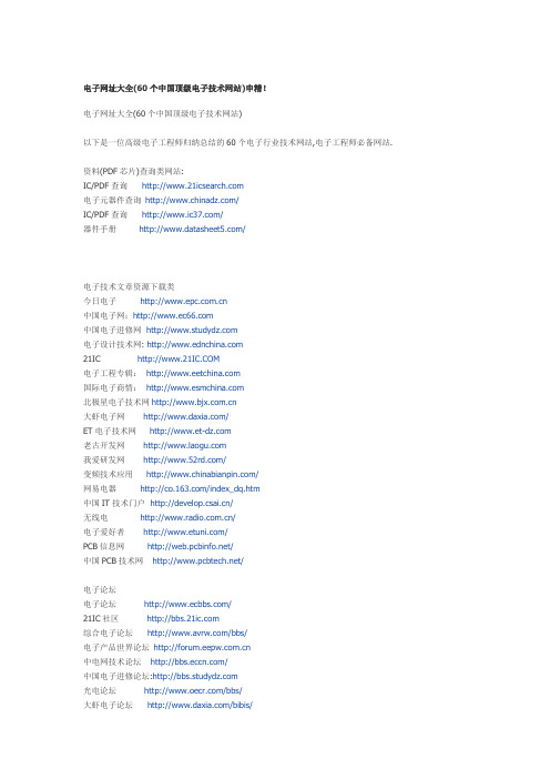
电子网址大全(60个中国顶级电子技术网站)申精!电子网址大全(60个中国顶级电子技术网站)以下是一位高级电子工程师归纳总结的60个电子行业技术网站,电子工程师必备网站.资料(PDF芯片)查询类网站:IC/PDF查询电子元器件查询/IC/PDF查询/器件手册/电子技术文章资源下载类今日电子中国电子网:中国电子进修网电子设计技术网: 21IC 电子工程专辑:国际电子商情:北极星电子技术网大虾电子网/ET电子技术网老古开发网我爱研发网/变频技术应用/网易电器/index_dq.htm中国IT技术门户/无线电/电子爱好者/PCB信息网/中国PCB技术网/电子论坛电子论坛/21IC社区综合电子论坛/bbs/电子产品世界论坛中电网技术论坛/中国电子进修论坛:光电论坛/bbs/大虾电子论坛/bibis/电子工程世界论坛国际电子技术论坛/伟纳单片机论坛/forum.asp中国PCB论坛/index.htm家电论坛广播论坛EDA专业论坛/bbs/研发BBS /bbs/电子工程博客中国电子工程博客/blog21IC博客工控博客/电源网博客/blog/EDA博客/blog中国电子网博客电子人博客中国子设计网博客中电网博客/进修博客/html/blog.html 工控博客电路图电子电路图网:电路图/单片机类单片机平凡网单片机/AVR单片机/周立功单片机/home.asp晶控电子/PIC学习网:嵌入式技术网/DSP专业资讯网/。
深圳雷迪司科技股份有限公司模块化在线式不断电系统使用者手册说明书

服务热线:400-6655-778使用者手册模块化在线式不断电系统深圳雷迪司科技股份有限公司目录1. 安全事项 (1)1.1 重要安全指示 (1)1.2 电磁波防护 (1)1.3 安装信息 (1)1.4 维修 (1)1.5 回收旧电池 (2)2 运作架构 (3)3. 安装 (4)3.1 结构和外观 (4)3.1.1 机柜规格 (5)3.1.2 机柜解说图 (6)3.2 内部构造 (8)3.2.1 输入和输出的断路器 (8)3.2.2 接线端子台 (9)3.2.3 模块 (10)3.3 控制面板和接口 (11)3.3.1 LED 指示灯 (11)3.3.2 液晶显示器 (12)3.3.3 功能键 (12)3.4 安装和接线 (12)3.4.1 安装前的注意事项 (12)3.4.2 安装环境 (12)3.4.3 搬运 (13)3.4.4 拆箱 (14)3.4.4.1 设备包装 (14)3.4.5 定位 (15)3.5 模块 (15)3.5.1 电力模块 (15)3.5.2 安装电力模块 (16)3.5.3 移除电力模块 (17)3.5.4 STS 模块 (17)3.5.5 移除STS 模块 (18)3.5.6 电池安装 (18)3.6 电源电缆 (19)3.6.1 交流输入和输出的最大电流和电力电缆规格 (20)3.6.2 直流最大电流和电力电缆规格 (20)4. 控制面板和显示区域 (21)4.1 简介 (21)4.2 显示内容 (23)4.2.1 起始画面 (23)4.2.2 主画面 (23)4.2.3 选单画面 (24)4.2.4 控制(CONTROL)画面 (24)4.2.5 测量数据(MEASUREMENT)画面 (25)4.2.6 设定(SETUP)画面 (27)4.2.6.1 设定选单之一般子选单(GENERAL) (29)4.2.6.2 设定选单之系统子选单(SYSTEM) (31)4.2.6.3 设定选单之电池子选单 (34)4.2.6.4 预报警画面 (36)4.2.6.5 并机画面 (37)4.2.7 信息画面(INFORMATION) (38)4.2.8 事件(EVENTS)选单画面 (39)4.2.8.1 目前事件 (40)4.2.8.2 历史纪录 (40)4.2.8.3 清除所有事件 (41)4.3 警告清单 (42)5. 接口及通讯 (45)5.1 远程EPO输入埠 (45)5.2 BCB 埠 (46)5.3 维修旁路开关状态埠 (46)5.4 内部输出开关状态埠 (47)5.5 电池柜温度侦测端口 (47)5.6 旁路反馈控制埠 (48)5.7 电池断路器控制埠 (48)5.8 其他通讯接口 (49)6. 维修保养 (50)6.1电力模块、STS控制模块、电池模块的更换步骤 (50)6.1.1 注意事项 (50)6.1.2 电力模块更换步骤 (50)6.1.3 STS控制模块的维修保养步骤 (51)6.1.4 电池模块更换步骤 (51)6.2空气滤网的更换步骤 (52)7.规格 (53)7.1兼容性和标准 (53)7.2环境特性 (53)7.3机柜特性 (54)7.4 电气特性(输入整流器) (54)7.5电气特性(直流电路) (55)7.6电气特性(逆变/变频器输出) (55)7.7电气特性(旁路电源输入) (56)1. 安全事项1.1 重要安全指示此UPS 设备带有致命性的电压,任何相关的维修作业应交由授权的技术人员实施。
DW800E使用说明书

3.6.3.1 3.6.3.2 3.6.3.3 3.6.3.4
3.6.4 3.6.5 3.6.6 3.6.7 3.6.8 3.6.9 4
开关量输入信号 ..............................................................................................................................................13 继电器控制输出 ..............................................................................................................................................13 脉冲输出..........................................................................................................................................................13 通讯................................................................................................................................................................. 14 模拟量输入......................................................................................................................................................15 模拟量输出......................................................................................................................................................16
SIEMENS ET200SP 西门子 ET200SP 分布式 IO 系统手册

合格的专业人员
本文件所属的产品/系统只允许由符合各项工作要求的合格人员进行操作。其操作必须遵照各自附带的文件说 明,特别是其中的安全及警告提示。 由于具备相关培训及经验,合格人员可以察觉本产品/系统的风险,并避 免可能的危险。
按规定使用 Siemens 产品
请注意下列说明:
商标 责任免除
警告 Siemens 产品只允许用于目录和相关技术文件中规定的使用情况。如果要使用其他公司的产品和组件,必须 得到 Siemens 推荐和允许。正确的运输、储存、组装、装配、安装、调试、操作和维护是产品安全、正常 运行的前提。必须保证允许的环境条件。必须注意相关文件中的提示。
Siemens AG Digital Industries Postfach 48 48 90026 NÜRNBERG 德国
A5E03576855-AK Ⓟ 05/2021 本公司保留更改的权利
Copyright © Siemens AG 2012 - 2021. 保留所有权利
前言
前言
本文档的用途
(https:///cs/ww/zh/ps/13716) • SIMATIC S7-1200/SIMATIC S7-1200F
(https:///cs/ww/zh/ps/13683) • 分布式 I/O (https:///cs/ww/zh/ps/14029) • STEP 7 (TIA Portal) (https:///cs/ww/zh/ps/14667)
ABB-Welcome IP H8236-._H8237-. 智能终端说明书
2TMD042000D0058│ 20.08.2021产品手册ABB-Welcome IPH8236-._H8237-. 智能终端1使用说明 (7)2安全 (7)3按规定使用 (8)4环境 (10)4.1ABB设备 (10)5产品描述 (11)5.1设备类型 (11)5.2控制元件 (13)5.3接口描述 (14)6技术参数 (16)7安装 (18)7.1对电工的要求 (18)7.2产品尺寸 (19)7.3安装高度 (19)7.4表面式安装 (20)7.5嵌入式安装 (22)7.6空心墙安装 (23)7.7桌面安装 (24)7.8拆卸 (25)7.9更换铭牌条 (25)8设置 (26)8.1初始化设置 (26)8.2主页 (30)8.3扩展页面 (31)8.4切换页面 (32)8.5系统设置 (33)8.5.1进入系统设置 (33)8.5.2声音 (34)8.5.3语言 (35)8.5.4网络设置 (36)8.5.5自动抓拍 (42)8.5.6离家留言设置 (43)8.5.7开锁按钮设置 (48)8.5.8可编程按钮设置 (51)8.5.9自动开锁设置 (57)8.5.10卡管理 (61)8.5.11显示 (65)8.5.12日期和时间 (66)8.5.13家庭监视设置 (67)8.5.14社区监控 (73)8.5.15App设置 (74)8.5.16修改密码 (84)8.5.17恢复用户设置 (90)8.5.18重置工程密码 (91)8.5.19版本信息 (92)8.5.20设备地址 (93)8.5.21获取产品手册 (94)8.5.22升级固件 (95)8.6工程设置 (97)8.6.1进入工程设置 (97)8.6.2进入【本机设置】页面 (99)8.6.3呼叫模式设置 (100)8.6.4设备模式设置 (102)8.6.5家庭网络端口设置 (105)8.6.6默认主页设置 (106)8.6.7功能管理 (107)8.6.8屏保图片设置 (108)8.6.9默认管理机设置 (109)8.6.10导出配置文件 (110)8.6.11导入配置文件 (111)8.6.12兼容模式设置 (112)8.6.13远程控制设置 (113)8.6.14清除所有数据 (114)8.6.15密码管理 (115)8.6.16认证列表 (116)8.7KNX 设置 (126)8.7.1先决条件 (126)8.7.2KNX 基本设置 (127)8.7.3KNX 高级设置 (135)8.7.4KNX 定时 (140)8.7.5KNX面板模式 (148)8.8free@home 设置 (149)8.8.1先决条件 (149)8.8.2free@home 设置 (150)8.9报警设置 (153)8.9.1防区连接 (153)8.9.2防区容量 (155)8.9.3先决条件 (158)8.9.4防区基本设置 (159)8.9.5防区高级设置 (161)8.9.6关联智能家居 (167)8.9.7关联KNX设备 (170)8.10门口机设置 (173)8.10.1先决条件 (173)8.10.2进入【门口机设置】页面 (174)8.10.3设备类型设置 (175)8.10.4刷卡开锁类型设置 (180)8.10.5默认锁设置 (181)8.10.6辅助锁设置 (182)8.10.7门状态检测设置 (183)8.10.8防拆报警设置 (184)8.10.9铃声音量设置 (185)8.10.10按键音设置 (186)8.10.11语音提示设置 (187)8.10.12语言设置 (188)8.10.13电梯联动设置 (189)8.10.14防闪烁设置 (190)8.10.15呼叫转移设置 (191)8.10.16韦根设置 (192)8.10.17按键设置 (193)8.10.18时间同步设置 (195)8.10.19兼容模式设置 (196)8.10.20升级固件 (197)8.10.21查看版本 (199)8.10.22查看序列号 (200)8.11IP actuator 设置 (201)8.11.1先决条件 (201)8.11.2进入【IP actuator 设置】页面 (202)8.11.3设备类型设置 (203)8.11.4功率锁设置 (208)8.11.5继电器锁设置 (209)8.11.6开锁上报设置 (210)8.11.7出门按钮设置 (211)8.11.8门状态检测设置 (212)8.11.9升级固件 (213)8.11.10查看版本 (215)8.11.11查看序列号 (216)9操作 (217)9.1来电 (217)9.1.1从门口机/围墙机呼叫 (217)9.1.2从管理机/室内机呼叫 (219)9.1.3从门铃呼叫 (220)9.2内呼 (221)9.2.1进入【内呼】页面 (221)9.2.2启动对讲呼叫 (222)9.2.3将联系人添加到黑名单 (229)9.2.4从黑名单恢复联系人 (231)9.3监视 (232)9.3.1从门口机进行监视 (232)9.3.2从 IP 摄像头监视 (234)9.4呼叫管理机 (235)9.4.1先决条件 (235)9.4.2发起呼叫 (236)9.5报警 (237)9.5.1进入【报警】页面 (237)9.5.2手动布防 (238)9.5.3手动撤防 (240)9.5.4自动布防 (241)9.6历史记录 (245)9.6.1查看呼叫记录 (245)9.6.2在黑名单中添加联系人 (247)9.6.3将快照复制到 SD 卡 (248)9.6.4删除呼叫记录 (249)9.6.5查看报警记录 (250)9.7语音信息 (252)9.7.1新建语音信息 (252)9.7.2读取语音信息 (253)9.7.3删除语音信息 (254)9.8文本信息 (256)9.8.1进入【文本信息】页面 (256)9.8.2发送文本信息 (257)9.8.3回复文本信息 (259)9.8.4将所有文本信息标记为已读 (261)9.8.5删除文本信息 (262)9.9待机开锁 (263)9.9.1进入【待机开锁】页面 (263)9.9.2添加锁 (264)9.9.3开锁 (266)9.9.4编辑锁 (267)9.9.5删除锁 (268)9.10媒体播放器 (269)9.10.1进入【媒体播放器】页面 (269)9.10.2播放音频或视频 (270)9.10.3播放照片 (271)9.11呼叫电梯 (272)9.11.1先决条件 (272)9.11.2呼叫电梯 (273)9.12PM 2.5值 (274)9.13擦屏 (275)9.14充电桩 (276)9.14.1先决条件 (276)9.14.2设置充电桩 (277)9.14.3手动充电 (278)9.14.4定时充电 (280)10网络安全 (282)10.1免责声明 (282)10.2性能与服务 (283)10.3布防指南 (284)10.4升级 (284)10.5备份/恢复 (284)10.6恶意软件预防方案 (284)10.7密码规则 (284)注意事项 (285)1使用说明请仔细阅读本手册,并遵守其中所含的信息。
工业机器人设备清单

空气动力机械智能制造公共实训基地设备预算清单模块一工业机器人基础工作室一、工业机器人基本技能工作室总体概述工业机器人基本技能实训方案以6轴机器人工作站为核心,配套装配了操作对象承载平台、工具墙、零件箱、学习讨论区、资讯区、机器人安全工作围栏等设施设备及基础教材、仿真软件、工学结合工作页等教学配套。
为工业机器人基本技能实训提供了综合的、完整的、工学结合的解决方案。
针对工业机器人应用维护专业基础技能训练与实习,该阶属于机电工学结合类技能向工业机器人过渡的关键环节,通过简单易操作的机器人本体操作的学习,加强安全意识与规范意识的培养,让学生掌握如何与工业机器人“打交道”。
工业机器人基本技能工作室案例照片(仅供参考)(图片仅供参考、以实际二、工业机器人基本技能工作室配置清单个;高强度铝合金手电筒(3节7号电池)6LED 1个;专业级手动黄油枪400cc 1个;手用黄油枪尖嘴头 1个;手用黄油枪软管12" 1个;德式轴用直口卡簧钳7" 1把;活动扳手10" 1把;木柄安装锤45MM 1把;T 系列双头螺丝批#1&5MM×150MM 1个;2.5MM系列钢柄快脱棘轮扳手 1把;预置式扭力扳手3件套;9件套公制长球头内六角扳手 1套;塑料工具箱19" 1把;吊带1条;卸扣 2个;工业听诊器 1把10、护栏①范围:2980mm×2980mm×920mm②材质:铝型材★含工业机器人拆装与调试课程资源包1、《工业机器人拆装与调试》教材配套教学ppt一套,试题3套、课程标准1套(现场演示)2、★《工业机器人拆装与调试》跨终端网络课程1门:★基于html5开发,课程栏目满足自适应,功能栏目为首页、课程简介、课程学习、★模拟考试(可进行在线考试)、拓展资源;(现场演示)3、《工业机器人拆装与调试》网络课程符合scorm封装标准4、★7个机器人拆装重难点微课;(现场演示)5、批量六关节机器人拆装素材库、视频素材库、教材配套素材库6、提供资源能学辅教,设备与网络课程及资源库能够完整对应。
电子电气产品抗电强度试验的应用
电子电气产品抗电强度试验的应用摘要:电子电气产品的生产过程以及原材料的选择变得越来越复杂,不同电子电气产品所采用的生产工艺存在较大差异性,产品的质量也有着明显区别。
因此电子电气产品的质量检测和质量控制变得十分重要,在出厂前需要制定合理的方案进行质量检测,满足电子电气产品的相关标准要求。
基于此,本篇文章对电子电气产品抗电强度试验的应用进行研究,以供参考。
关键词:电子电气产品;抗电强度试验;应用分析引言电气强度测试在电子产品的安全检查中非常常见,主要用于检查绝缘的可靠性,特别是在对不可见间隙或空隙进行筛选时。
此外,电气强度测试经常用于环境预处理和破坏性检测后设备绝缘可靠性的再检测。
电气强度试验被广泛使用,因为它在一定程度上忽略了设备结构,并且可以在一定条件下替代绝缘电阻试验。
1抗电强度试验原理根据过电压类别和设备的绝缘程度,电气强度测试通常将产品的输入端连接到电气强度测试设备,另一端连接到产品的输出端(见图1)。
这是一个简单快速的基准测试,通过对绝缘系统应用指定的电压值来确定绝缘系统是否在该电压下被破坏,很多标准都有这个测试要素。
在电气强度测试期间测试的绝缘系统在给定电压得到认可时不能超过电流限制。
认可给定电压后,电流不受控制地呈指数增长,也就是说,它突破了。
在测试过程中,应注意测试电压必须准确地应用于绝缘系统,原应提供主绝缘体的绝缘体和附加绝缘电压不得暴露在电压下,以加强绝缘。
在进行电气强度测试时,必须首先使用点电阻检查耐电压计的信号功能,因此,必须确保持续电压计不会因开放的测试线路电路和导致错误评价的其他原因而对警报做出反应。
一般来说,内战压力计的泄漏电流警报标准设置为10毫安以上,但这并不意味着警报警报一定会发生故障。
电容器(如电容器Y)通过绝缘连接时,电容器的AC和DC绝缘特性可能会导致电阻测试期间泄漏电流增加,报警响应将由过量的报警电流触发。
在这种情况下,直流电压可用于验证。
如果绝缘系统装有在高电压下可能处于导电状态的闪电管或压力感应部件(见图2)、或特定电阻器(见图3)、整个绝缘中装有电感和绕组等部件,从而干扰测试,则某些部件可以通过电路开口进行测试。
KJ95X煤矿安全监控系统

内蒙古平庄能源股份XXX风水沟矿KJ95X煤矿安全监控系统技术协议甲方:内蒙古平庄能源股份XXX风水沟煤矿乙方:天地(常州)自动化股份XXX2018年1月目录一、总则 (1)二、系统设计依据 (1)三、系统主要功能 (3)四、系统性能指标 (4)五、主要设备技术参数 (4)六、工程责任 (12)1.系统质保 (12)2.工程实施 (12)3.甲方责任 (13)4.乙方责任 (13)七、服务承诺 (14)1.技术培训 (14)2.售后服务 (14)八、设备清单 (14)九、其它 (19)十、双方签字盖章 (19)甲方:内蒙古平庄能源股份XXX风水沟煤矿乙方:天地(常州)自动化股份XXX甲乙双方经充分协商,就内蒙古平庄能源股份XXX风水沟煤矿安全监测监控系统工程安装及系统设备达成如下技术协议:总则本合同系统使用单位为:风水沟煤矿本次升级改造采用天地(常州)自动化股份XXX生产的KJ95X煤矿安全监控系统,通过新技术、新装备的应用,提高安全监控系统技术性能和安全可靠性,适应煤矿安全生产的需要,充分发挥安全监控系统在煤矿安全生产中的重要作用。
本次项目合同中的软、硬件货物全部按照甲方招标清单要求供货,其他所涉及到的货物不在本次合同范围之内。
系统能实现的功能或要求是指甲方所采购的货物满足KJ95X煤矿安全监控系统配置情况下实现的。
系统设计依据➢《煤矿安全规程》现行2016版➢国家煤矿安监局关于印发《煤矿安全监控系统升级改造技术方案》的通知煤安监函〔2016〕5号➢《煤矿安全监控系统通用技术要求》AQ6201-2006➢《煤矿安全监控系统及检测仪器使用管理规范》AQ1029-2007➢国家安全监管总局办公厅关于印发《煤矿安全生产在线监测联网备查系统通用技术要求和数据采集标准(试行)》的通知安监总厅规划(2016)138号➢《国家安全监管总局国家矿井安监局关于建设完善矿井井下安全避险“六大系统”的通知》(安监总煤装〔2010〕146号文件)➢《煤矿用低浓度载体催化式甲烷传感器》AQ6203-2006➢《瓦斯抽放用热导式高浓度甲烷传感器》AQ6204-2006➢《煤矿用电化学式一氧化碳传感器》AQ6205-2006➢《煤矿用高低浓度甲烷传感器》AQ6206-2006➢《煤矿安全生产监控系统通用技术条件》MT/T1004-2006➢《煤矿安全生产监控系统软件通用技术要求》MT/T1008-2006➢《煤矿用信息传输装置》MT/T899-2000➢《矿用分站》MT/T1005-2006➢《矿用信号转换器》MT/T1006-2006➢《矿用信息传输接口》MT/T1007-2006➢《煤矿监控系统线路避雷器》MT/T1032-2007➢《矿用光纤接、分线盒》MT/T1033-2007➢《矿用网络交换机》MT/T1081-2008➢《电子计算机场地通用规范》GB/T2887-2000➢《计算机软件开发规范》GB8566-2007➢《煤炭工业矿井设计规范》GB50215-2005➢《煤炭工业矿井监测监控系统装备配置标准》GB50581-2010➢《综合布线系统工程验收规范》GB50312-2007➢《光纤总规范》GB-T15972.1~5-1998➢《爆炸性环境电气设备通用要求》GB3836.1-2010➢《爆炸性环境第1部分:设备通用要求》GB 3836.1-2010➢《爆炸性环境第2部分:由隔爆外壳“d”保护的设备》GB 3836.4-2010 ➢《爆炸性环境第4部分:由本质安全型“i”保护的设备》GB 3836.4-2010 ➢《矿井通信、检测、控制用电工电子产品通用技术条件》MT209-1990➢《矿井井下紧急避险系统建设管理暂行规定》➢《全国工业产品生产许可》➢《中华人民共和国制造计量器具许可》系统主要功能(1)监控主机、传感器均具有分级报警功能,根据报警级别通知相关部门及负责人,实现报警信息分级响应;(2)具有自定义报表功能,可根据实际情况灵活定义报表;(3)具有Web发布功能,可查看实时及历史数据、报警、曲线等信息;(4)采用大容量数据库实现密采监测值数据存储,保证监控系统数据完整性;(5)具有数据加密功能,实现对监控系统配置信息、历史数据安全加密、存储;(6)具有传感器、电源、执行器的即插即用功能,系统自动识别所接设备类型,仅需配置设备安装地点及断电关系即可投入使用;(7)具有在线标校功能,系统软件自动标识、记录传感器标校状态,减少标校窗口时间,缩短监控时段盲区;(8)具有电源管理功能,实现智能电源实时在线监测和管理;(9)具有监控系统达标检测功能,通过构建矿井模型,检测矿井传感器漏装,报警、断电、复电门限设置错误等异常问题,并进行报警;(10)(根据清单配置删减该项要求)具有GIS图形展示功能,可矢量缩放、平移、鹰眼导航,实现图属联动功能,支持在Web在线编辑、CAD导入,可进行多系统融合信息综合展示、图层设置及显示;(11)(根据清单配置删减该项要求)具有地面多系统融合功能,实现多系统联动。
新天地电子(Newtons4th Ltd)N4L 7949 03 3kHz高频交流电源商品说明书

DC~3kHZ Bandwidth (10kHz small signal)Better than 0.3% THD Isolated OutputRegenerative Option0~270V & 0~135V RMS 0~11.1Arms & 0~22.2Arms ContinuousStackable Parallel OptionCombine units to create a 3 Phase system (Delta/Star)Newtons4th Ltd794903-Advanced Power SourcesHighIEC ENWhite Goods, Aerospace, Consumer Electronics, Single and Three PhaseParallel up to 9 units [27kVA] in single and 3 phase configirationArbitrary waveform generation including harmonic synthesis IEC61000 ComplianceSOURCE WITH A SINGLE PHASE UNIVERSAL INPUTPOWER ELECTRONICS EXPERTISE MEASUREMENT EXPERTISEQUALITYISO17025ACCREDITATIONMASTER8x SLAVESGROUP 1 50Hz 220V L-N0° Phase OffsetGROUP 1 50Hz 220V L-N120° Phase Offset GROUP 1 50Hz 220V L-N240° Phase OffsetR&DUSB, RS232, CAN and a Parallel networking bus to control the N4AX when in master-slave configuration.Input, Output and Sense terminals feature high quality removable connectors making connection and disconnection from a system extremely easy. Spare connectors are readily available from worldwide component stockists.There is also a Regen Option connector on the rear of the N4AX which facilitates connection to a regen unit. N4L will be releasing the regen unit during 2018.Waveform Example : DO-160 Section 16.5.1.2(Voltage modulation, AC)Waveform Example : DO-160 Section 16.5.1.4(Momentary Power Interruptions, AC)consumer electronics. An example application is development and test of AC/DC mobile phone chargers, where the N4AX can be paired up with a PPA500 or PPA1500 precision power analyzer to provide a complete measurement solution.The N4AX can be employed to generate a constant sinusoidal output, or it can be configuredto apply high levels of distortion, voltage sags or voltage surges to the device under test, forexample.AnalyzerAnalyzerand analysis of up to 6 DUT’s. The example below shows 6 mobile phone battery chargers being simultaneously powered and analyzed by the N4AX and PPA3500.components. This makes the N4AX able to generate power for both automotive inverter design and test applications as well as development and test of grid connected charging systems.immunity tests. The N4AX offers a very low distortion output which is a key requirement of the Harmonics and Flicker standard. The output impedance is also extremely low, a key performance IEC7949occur. The N4AX series of power sources are able to signal to the rest of the system that a fault has occured and immediate shut down of the system is initiated to protect the device under test as well as the remaining N4AX power sources. This is known as the “high speed kill function”.As N4AX power sources can act as a master and a slave, even if the original master unit is in fault condition one of the remaining N4AX units can take over master responsibilities and system operation can resume. (see example below)7949Newtons4th Ltd 1 Bede Island RoadLeicester LE2 7EAUKPhone: +44 (0)116 230 1066 Fax: +44 (0)116 230 1061Email:********************Web: copyright © 2010-2018 Newtons4th Document ref: N4AX/iss3/Mar_2018Newtons4th Newtons4th Ltd (abbreviated to N4L) was established in 1997 to design, manufacture and support innovative electronic equipment to a worldwide market, specialising in sophisticated test equipment particularly related to phase measurement. The company was founded on the principle of using the latest technology and sophisticated analysis techniques in order to provide our customers with accurate, easy to use instruments at a lower price than has been traditionally associated with these types of measurementsAll specifications at 23˚C ± 5˚C . These specifications are quoted in good faith but Newtons4th Ltd reserves the right to amend any specification at any time without notice.Contact your local N4L Distributor for further detailsDistributed By :Flexibility in our products and an attitude to providing the solutions that our customers really want has allowed us to develop many innovative functions in our ever increasing product range(Sales, Support, Calibration)。
西门子低压配电

值得信赖的伙伴“上海西门子线路保护系统有限公司”成立于一九九六年,致力于向中国用户提供德国西门子最新建筑电气技术和产品。
其中5SJ系列小型断路器、5SY系列小型断路器、5SU9系列电子式漏电保护断路器、5SM系列电磁式漏电保护装置、3NA3系列熔断器等产品在中国建筑和工业领域得到广泛应用,为用户安全用电提供了可靠的保障。
中国市场认证上海西门子线路保护系统有限公司,通过了ISO 9001的国际认证。
西门子严格完整的质量保证体系使所有在中国制造和销售的产品均取得了国家强制性的3C认证证书。
优质的产品得到用户的一致青睐,并荣列建筑部住宅建设推荐产品之首。
优质服务西门子(中国)有限公司下设二十四个分支机构与中国各地五十多家经销商和千余家零售分销商紧密合作,为用户提供全系列的建筑电气产品和优质服务。
网络支持:/products/et/我们的在线支持为您提供: 产品和系统信息 营销活动 产品和系统应用 新闻和咨询 培训作为世界最大电子电气公司之一的西门子,在信息、通讯、输配电、交通、医疗、建筑、家电、照明等领域里不懈努力,着力研发,一直引领着科技前沿。
西门子全球年销售额超过800亿欧元。
拥有120年悠久历史的西门子建筑电气更是秉承西门子德国精益求精的严谨风格,立足中国开发,为蓬勃发展的中国建筑和工业领域提供完整的电气解决方案以及安全、可靠、高品质的产品和服务。
西门子建筑电气从传统的配电保护产品到现代楼宇的智能控制系统,均能给用户提供灵活多样的选择。
目录MCB 小型断路器RCD 漏电保护装置配电箱Fuse 熔断器1.5SJ4、5SJ5、5SJ6(标准型)、5SJ7、5SP4小型断路器2.5ST3分励脱扣器(ST)3.5ST3欠压脱扣器(UR)4.5ST3辅助接点(AS)5.5ST3故障信号接点(FC)6.5SM2漏电保护模块7.汇流排(除5SP4外)8.手柄锁定装置9.挂锁178ST UR AS FC962345*5SY3..KV,5SY6..KV 的AS 、FC 装于断路器左侧小型断路器快速选型表快速选型举例:极数额定电流脱扣曲线分断能力代码(6K A )型号5S J 6 C 16A 2P 5S J 系列小型断路器的控制附件均拼装在断路器的右边5S J 7,5S J 6(标准型),5S J 4小型断路器可在断路器的左边拼装5S M 2漏电模块控制附件可与楼宇自动化i n s t a b u s E I B (欧洲安装总线)和传感器总线连接5S P 4小型断路器除80A 以上不可拼装现有5S M 2外,其余附件使用同上述漏电保护装置快速选型表注:1P+N,AC型,30mA,6KA为4个缺省参数,选型时可省略。
XB6 系列_ EtherNet IP_插片式 I O 用户手册说明书

2.1
命名规则 .......................................................................................................................................................... 3
EtherNet/IP XB6 系列插片式 I/O 用户手册
南京实点电子科技有限公司
版权所有 © 南京实点电子科技有限公司 2023。保留一切权利。 非经本公司书面许可,任何单位和个人不得擅自摘抄、复制本文档内容的部分或全部,并不得以任何形式传播。 商标声明
和其它实点商标均为南京实点电子科技有限公司的商标。 本文档提及的其它所有商标或注册商标,由各自的所有人拥有。 注意 您购买的产品、服务或特性等应受实点公司商业合同和条款的约束,本文档中描述的全部或部分产品、服务或特性可 能不在您的购买或使用范围之内。除非合同另有约定,实点公司对本文档内容不做任何明示或默示的声明或保证。 由于产品版本升级或其他原因,本文档内容会不定期进行更新。除非另有约定,本文档仅作为使用指导,本文档中的 所有陈述、信息和建议不构成任何明示或暗示的担保。
3.3
接口参数 .......................................................................................................................................................... 8
5.2
安装拆卸步骤 .............................................................................................................................................. 19
洛阳贝尔电气PLD2008A3说明书

² 在系统运行时,请按正确的操作步骤进行操作,否则可能造成非法操 作,引起不必要的损失。
3
2、系统组成: PLD2008A3 系统主要组成有计算机、XK-3110G2 型管理仪表(1 块)、
XK-3110A-SE 配料控制器(4 块),其连接图如下所示。
1.2 软件组成
PLD2008A3 软件包括《PLD2008A3 型混凝土生产自动控制系统》、辅助 工具软件《PLD2008A2 单据编辑器》、FastReport 编辑器及数据库压缩软件。 其中辅助工具软件可选配安装。
PLD2008A3 软件可为客户量身定制,并不断推出新版本,欢迎访问我们 的网站 ,获取更多更新的产品资讯。 1.3 版权声明
7、报警及故障处理 ...............................................................18 8、常见问题 ...........................................................................19
4
3、安装 双击光盘上的“setup.exe”,开始安装进入如下界面,
单击【Next>】,
5
单击【Yes】,
单击【Next>】,
6
单击【Next>】,
单击【Next>】,
7
单击【Next>】,
单击【Next>】,
8
单击【Finish】。安装完成。 4、使用
4.1 启动:
双击桌面上 图标;出现如下用户登陆对话框,输入用户名和密码; 单击确定或回车。若用户名及密码正确,则可以进入控制系统。
schneider Delta锐智4系列 VDI Box智能信息布线箱 产品手册

Delta 锐智4系列产品手册2010施耐德电气VDI Box智能信息布线箱智能家居从布线开始,让家实现您的自由畅想1家庭和小型办公场所网络的灵魂The backbone for the home and small size office.可以把语音、数据、视频信号(简称VDI )传输到各个房间的信息插座:智能信息布线箱V D I B o x 电 视电 话宽 带2专利外观设计,符合现在美学施耐德电气为能够提供时尚和流线型产品感到自豪。
这已经不是简单的功能和使用上的满足,也具有装饰作用,使其能够和各种房屋内部环境完美的融合。
快捷式模块化设计模块拆卸方便。
对于用户,快捷式模块化设计能够提高重新接线的效率,减少停机修理的时间,同时也能减少不必要的维护开销。
简单维护,轻松安装在智能布线箱面世之前,计划、实施和管理一个住宅布线系统,通常都会一片混乱。
有了布线箱的帮助,所有的设备增加,功能取消和修改都变的轻而易举。
更改具体某个端口的应用不再是一场灾难。
施耐德电气智能布线箱的独特设计,使得安装、维护都异常轻松,无需专门的培训即可操作。
施耐德电气智能布线箱不仅仅能解决智能网络问题,它也是一个能够有效令开发项目增值的手段,同时又是区分你和其他传统住宅项目的有效方案。
Ordered Stylish Easy Convenient所有这些利益,业主都能轻松享受●天花板上、地毯下和墙角边,线缆不再杂乱无章。
●可以在卧室、厨房愉悦地欣赏电影。
●不同房间的人可以观看不同的媒体。
●通过电视屏幕得知访客的身份和家中情况。
●通过外置无线AP,实现在家中自由无线冲浪。
●在沙发上,用笔记本电脑在书房的打印机上操作。
●只需一个机顶盒,在家里任何地方都可以观看有线电视/付费电视。
●可以在任意数据端口实现IPTV的应用。
●让家实现你的自由畅想3智能家居布线系统将为您的家居生活带来轻松享受:●天花板上、地毯下和墙角边,线缆不再杂乱无章;●帮您组建家庭局域网,家里的多台电脑可互相访问,实现资源共享;●只需要一个机顶盒,在家里任何地方都可以观看有线电视/付费电视;●您可以在卧室、厨房愉悦地欣赏电影,在沙发上,用笔记本电脑在书房的打印机上操作。
电子伏特利亚电子倒扣单元TD012054EN商品说明说明书
ContentsDescriptionPageCatalog number selection . . . . . . . . . . . . . . . . . . . . . . . . . . . . . . . . . . . . . . . . . . . . . . . . . . . . . . . . . . . . . . . . . . . . .3Digitrip RMS 310+ electronic trip unitsMDL, HMDL, CMDL, CHMDL, MDLB, HMLDB; 800A; 3- and 4-pole; LS and LSG . . . . .TD012051EN . . . . . . . . .6MDL, HMDL, CMDL, CHMDL, MDLB, HMLDB; 800A; 3- and 4-pole; LSI, LSIG,ALSI, ALSIG . . . . . . . . . . . . . . . . . . . . . . . . . . . . . . . . . . . . . . . . . . . . . . . . . . . . . . . . . . . .TD012052EN . . . . . . . .7Ground fault protection . . . . . . . . . . . . . . . . . . . . . . . . . . . . . . . . . . . . . . . . . . . . . . . . . . .TD012053EN . . . . . . . . .8Maintenance mode setting; ALSI and ALSIG . . . . . . . . . . . . . . . . . . . . . . . . . . . . . . . . . . .TD012054EN . . . . . . . . .9Digitrip RMS 310 electronic trip unitsMDL, HMDL, CMDL, CHMD; 800A; 3- and 4-pole; LS and LSG . . . . . . . . . . . . . . . . . . . . .SC-7204-99 . . . . . . . .10MDL, HMDL, CMDL, and CHMD; 800A 3- and 4-pole; LSI, LSIG, ALSI, ALSIG . . . . . . . . . .SC-6913-98 . . . . . . . .11Ground fault protection . . . . . . . . . . . . . . . . . . . . . . . . . . . . . . . . . . . . . . . . . . . . . . . . . . . . .SC-6914-98 . . . . . . . .12MT thermal/magnetic trip unitMDL, HMDL, MDLB, and HMDLB, 300-600A . . . . . . . . . . . . . . . . . . . . . . . . . . . . . . . . . .SC-6911-98 . . . . . . . .13MDL, HMDL, MDLB, and HMDLB, 700-800A . . . . . . . . . . . . . . . . . . . . . . . . . . . . . . . . . . .SC-6912-98 . . . . . . . .14Note:Time/current characteristic curves for series C M-frame circuit breakers--voltages shown in curve headings aremaximum at which the breaker may be applied . Interrupting capacity of individual breaker is tabulated on each curve .Note:The following curves are UL489 listed for use in North America .The following circuit breakers are derived from Eaton, Westinghouse, or Cutler-Hammer history .Time current curves are engineering reference documents for application and coordination purposes only. For field testing molded case circuit breakers, refer to NEMA AB 4 guidelines.Series C MDL-frame400-800A, 240-600Votee:NUnless noted below, all curves remain unchanged from their prior revision .2EATON Time Current Curves TD012036ENEffective February 2020Series C M-frame3EATON Time Current Curves TD012036ENEffective February 2020Series C M-frameCatalog number selectionThis information is presented only as an aid to understanding catalog numbers .It is not to be used to build catalog numbers for circuit breakers or trip units .MDL 3 800 FCircuit b reaker/Frame t ypeMDL, MDLB HMDL, HMDLBNumber of p oles23= Two-pole = Three-poleCircuit b reaker/f rame Ampere r ating300350400450500600700800SuffixF K V W X Y = Frame only= High magnetic molded case switch = 500C (thermal-magnetic trip units only)= Without terminals= Load side terminals only = Line side terminals onlyT able 2. Circuit breaker/frame11MT 3 800 TTrip u nit t ypeMT MESNumber of p oles23= Two-pole = Three-poleTrip u nitAmpere r ating300350400450500600700800SuffixT V LS LSI LSG LSIG = Thermal-magnetic= 500C (thermal-magnetic trip units only)= Digitrip RMS 310= Digitrip RMS 310= Digitrip RMS 310= Digitrip RMS 310T able 1. Thermal-magnetic trip unit11Note1 Thermal-magnetic only .Time Current Curves TD012036EN Effective February 2020Series C M-frameEATON MES 3 800 ALSIG B21Tripu nit t ype MESPoles3= Three Amperes800FeaturesBlankB20B21B22ZG= No feature= High load alarm= Ground faultalarm, with trip= Ground faultalarm, no trip= Zone selectiveinterlockingTrip u nitLSLSILSGLSIGALSIALSIG= 310+ e lectronic LS= 310+ e lectronic LSI= 310+ e lectronic LSG= 310+ e lectronic LSIG= 310+e lectronic LSI withm aintenance m ode= 310+ e lectronic LSIG withm aintenance m odeT able 4. MDL electronic trip unit MDLB 3 800 F T36 B21 WPerformance at 480 VacPoles3= ThreeAmperes800FeaturesBlank B20 B21 B22 ZG = No feature= High load alarm = Ground fault alarm, with trip = Ground fault alarm, no trip = Zone selective interlockingTrip u nitT33 T32 T35 T36 T38 T39= 310+ e lectronic LS= 310+ e lectronic LSI= 310+ e lectronic LSG= 310+ e lectronic LSIG= 310+ e lectronic LSI with m aintenance m ode= 310+ e lectronic LSIG with m aintenance m odeFramed esignationFMDLB HMDLB CMDLBCHMDLB = 50 kAIC= 65 kAIC= 50 kAIC100% rated= 65 kAIC100% ratedTerminalsW= No terminalsT able 3. MDL breaker assemblyMDL 3 800 F Performance at 480 VacPoles3= Three Amperes800Frame d esignation FMDL HMDL CMDL CHMDL = 50 kAIC = 65 kAIC = 50 kAIC 100% rated = 65 kAIC 100% ratedT able 5. MDL frame onlyNote1 Maintenance mode and ZSI are only available with LSI and LSIG trip units .2 B21 and B22 features available only with LSG, LSIG and ALSIG trip units .3 B2x suffixes cannot be combined with other B2x suffixes .45Time Current Curves TD012036ENEffective February 2020Series C M-frameEATON Figure 1. Digitrip 310+ faceplatesALSIG (with maintenance mode)LSLSILSGLSIGALSI (with maintenance mode)6Time Current Curves TD012036ENEffective February 2020Series C M-frameEATON Figure 2. Digitrip 310+ trip units (800A), long delay response and short delay with I 2T response curve and override (LS, LSG) - TD012051EN, February 20207Time Current Curves TD012036ENEffective February 2020Series C M-frameEATON Figure 3. Digitrip 310+ trip units (800A), long delay response and short delay with flat response curve and override (LSI, LSIG, ALSI, ALSIG) - TD012052EN, February 20208Time Current Curves TD012036ENEffective February 2020Series C M-frameEATON 0.0123456810203040506070809010010009008007006005004003002000.020.030.040.050.060.070.080.090.10.20.30.40.50.60.70.80.91792000300040005000600070008000900010,000et u n i M 1Ground Current in Multiple of (I n )0.10.20.30.40.50.7120.10.20.30.40.50.712Ground Fault Pickup Settings(Tolerance ±10%)0.4X 0.3X0.2X1X0.6X 0.8XInst.(J, M, P)120 ms (K, N, Q)300 ms (L, O, R)sd n o ce S n i e m i TFigure 4. Ground fault delay response curve (LSG, LSIG, ALSIG) - curve number TD012053ENDigitrip 310+ circuit breaker time/current curves (ground current)Series C M-frame circuit breakers (800A)Catalog types: MDL, HMDL, CMDL, CHMDL, MDLB, HMLDB T rip unit types: LSG, LSIG, ALSIG Notes:Curve accuracy applies from –20°C to +55°C ambient . For possible continuous ampere derating for ambient above 40°C, refer to Eaton .Digitrip RMS 310 trip units are suitable for functional field testing with test kit cat . No . STK2 .For field testing using primary injection methods, follow NEMA publications9Time Current Curves TD012036ENEffective February 2020Series C M-frame EATON 2.2.3.4.5 .6 .7 .8 .91345678910 2 .5Maintenance Mode TripN S E C O N D SFigure 5. Maintenance mode setting (ALSI, ALSIG) - curver number - TD012054EN, October 2014I r = Continuous current setting or rating plug value, I s = Current sensor frame rating,I n = Rating plug value, I g = Ground current pickup multiplier, I i = Instantaneous override pickup .ALSIALSIGFigure 6. MDL, HMDL, CMDL, and CHMDL, types MES3800LS and MES3800LSG - curve number SC-7204-99, June 2020T ypes MDL, HMDL, CMDL, and CHMDL equipped with type MES digitrip RMS 310 trip units, types MES3800LS and MES3800LSG10EATON Time Current Curves TD012036ENEffective February 2020Series CM-frameFigure 7. MDL, HMDL, CMDL, and CHMDL, types MES3800LSI and MES3800LSIG – curve number - SC-6913-98, June 2020T ypes MDL, HMDL, CMDL, and CHMDL equipped with type MES digitrip RMS 310 trip units, types MES3800LSI and MES3800LSIGTime Current Curves TD012036ENEffective February 2020Series C M-frame 11EATON Figure 8. MDL, HMDL, CMDL, and CHMD ground fault protection - curve number SC-6914-98, June 2007T ypes MDL, HMDL, CMDL, and CHMDL equipped with type MES digitrip RMS 310 trip units, ground fault protectionTime Current Curves TD012036ENEffective February 2020Series CM-frame 12EATON 13EATON Figure 9. MDL, HMDL, MDLB, and HMDLB, 300-600A - curve number SC-6911-98, June 2007T ypes MDL, HMDL, MDLB, and HMDLB equipped with type MT thermal-magnetic trip unit, 300 to 600 amperesTime Current Curves TD012036ENEffective February 2020Series C M-frame14Time Current Curves TD012036ENEffective February 2020Series CM-frameEATON Figure 10. MDL, HMDL, MDLB, and HMDLB, 700-800A - curve number SC-6912-98, June 2007T ypes MDL, HMDL, MDLB, and HMDLB equipped with type MT thermal-magnetic trip unit, 700 and 800 amperes15EATON Time Current Curves TD012036ENEffective February 2020Series C M-frameEaton1000 Eaton Boulevard Cleveland, OH 44122 United StatesEaton .com© 2020 EatonAll Rights ReservedPrinted in USAPublication No . TD012036EN / TBG001486 February 2020Eaton is a registered trademark .All other trademarks are propertyof their respective owners .Series CM-frameTime Current Curves TD012036EN Effective February 2020。
产品原理和功能

技术参数
新电气的倡导者
广州真善美电气有限公司 产品介绍
接线方式
新电气的倡导者
广州真善美电气有限公司 产品介绍
智能转接插
功能
◆适用于独立的灯光或电器,智能插座插入普通插座, 再将灯光或电器插座插入智能插座,即可实现灯光或电 器的无线控制 ◆ 中转接力功能:具有中转功能,加强接收信号的准确 性
新电气的倡导者
新电气的倡导者
质量体系
广州真善美电气有限公司 产品介绍
新电气的倡导者
广州真善美电气有限公司 产品介绍
欧洲CE认证 欧洲 认证
新电气的倡导者
广州真善美电气有限公司 产品介绍
新加坡PSB认证 新加坡 认证
新电气的倡导者
中国强制认证
广州真善美电气有限公司 产品介绍
新电气的倡导者
样板房
广州真善美电气有限公司 产品介绍
新电气的倡导者
广州真善美电气有限公司 产品介绍
远程控制效果图
GKB服务器 解调器 路由器
GKB网络主 机
PSTN
新电气的倡导者
广州真善美电气有限公司 产品介绍
家居内部控制效果图
RF
新电气的倡导者
广州真善美电气有限公司 产品介绍
液晶面板
新电气的倡导者
广州真善美电气有限公司 产品介绍
功能
◆ 遥控功能:可穿墙及障碍物遥控操控 ◆集中显示:可显示各处灯光及电器的工 作状态 ◆集中控制:一个液晶面板可控制全屋灯光 及电器 ◆全开/全关功能:可一次性全部打开或全 关全屋灯光及电器 ◆多点控制:多个面板可控制同一处灯光 ◆夜光功能:提供蓝色背景灯光,即使晚上 也控制自如
广州真善美电气有限公司 产品介绍
技术参数
工业电气设计中电气节能技术的应用陈思杰1许维帝2
工业电气设计中电气节能技术的应用陈思杰1 许维帝2发布时间:2021-07-28T10:57:00.853Z 来源:《基层建设》2021年第14期作者:陈思杰1 许维帝2 [导读] 工业的发展深受国家政府和大众的关注,其节能减排的呼声也在不断增加1身份证号码:35062319930518XXXX;2身份证号码:35020619880808XXXX 摘要:工业的发展深受国家政府和大众的关注,其节能减排的呼声也在不断增加。
为了让我国的工业发展能够更上一层楼,为了绿色节能的环保事业,为了大众更好的生活水准,工业电气的节能技术需要与时代一同成长,在实际的电气设计中要切实落实到实处,科学设计出具有可行性、经济适用的方案,严格按照规章制度执行,全方位地提高工业电气设计的使用效率,让节能理念充分贯彻到企业,推动经济社会的发展。
本文主要对工业电气设计中电气节能技术的应用进行探讨。
关键词:工业电气设计;节能技术;应用一、简述我国的工业电气设计工业电气设计,顾名思义就是工业建设中电力资源的设计使用方案,这是工业建设中的重要部分,对其起着非常重要的作用。
现如今,由于多种因素影响,我国的电气节能面临着挑战。
第一,我国的工业发展迅速,不同的工业生产有不同的工艺设计,对节能减排的标准也尚未明确统一。
第二,我国的部分工业企业还未认识到节能的重要性,依然把经济建设放在第一位置,忽视了节能措施。
第三,电气节能的设计应用需要资金维持,我国大部分的中小型工业企业没有充足资金投入节能设计等。
种种困难因素阻碍了电气节能在企业建设中的普遍应用,因此,我国的工业电气节能还在进一步摸索当中。
二、电气节能技术在工业电气设计中的应用措施为了加强我国的电气节能技术在工业施工中的实践应用,应该在电气设计的各个环节把关,以此减少能源消耗,能够最大程度地节约利用资源,为我国的电气节能进程写下里程碑式的一笔,达到科学节能的发展战略。
(一)供配电系统的节能设计输配电工程是输电和配电两个部分组成的,两个部分共同协作,将电能从总配电区域输送到用户。
- 1、下载文档前请自行甄别文档内容的完整性,平台不提供额外的编辑、内容补充、找答案等附加服务。
- 2、"仅部分预览"的文档,不可在线预览部分如存在完整性等问题,可反馈申请退款(可完整预览的文档不适用该条件!)。
- 3、如文档侵犯您的权益,请联系客服反馈,我们会尽快为您处理(人工客服工作时间:9:00-18:30)。
[单片机][msp430的电子图书]精品 wu90909
2006-05-21 1 17 2006-05-22 20:24
by: liaolibin
信号与系统 东南大学 wu90909
2006-05-21 1 19 2006-05-22 19:43
by: mxlvzxp
从C51初学者到电子工程师(初学者请看) wu90909
2006-04-18 15 428 2006-05-22 15:25
by: yxw888
电子线路 南京航空航天大学 wu90909
2006-05-21 1 20 2006-05-22 14:52
by: stxrh
电子镇流器设计(台湾中山大学博士论文) wu90909
2006-04-08 2 86 2006-04-20 08:32
by: wendy2004
吉林大学-电路电子技术化76讲 csf格式 wu90909
2006-04-08 3 131 2006-04-18 18:07
2006-04-08 0 68 2006-04-08 20:01
by: wu90909
多路报警器电路 wu90909
2006-04-08 0 50 2006-04-08 19:58
by: wu90909
音频无线传输-红外发射电路 wu90909
2006-04-08 0 42 2006-04-08 19:53
by: moul
[石油大学][电工电子学][33讲][csf格式] wu90909
2006-04-08 2 105 2006-04-16 21:38
by: moul
《CDMA 蜂窝移动通信与网络安全》 方正apabi联盟制作 wu90909
2006-04-16 0 32 2006-04-16 16:45
网站链接是:/?a=14 。这个论坛才刚刚建立,希望大家多多参与,人人都有机会做版主。
/?a=14
电子电气/宝贝天地专区在天天互动成立/?a=14,大家有空多来看看,有很多好资源共享一般在/?a=14天天互动发布之后等到有源了再到VC发布.想第一时间下到好东东就来/?a=14找找看.
by: xiao2006
电子资料下载(HTTP下载) wu90909
2006-04-11 5 416 2006-04-21 14:17
by: wwx330
CSF课件解密方法(对没法放的,加密的CSF文件请用这个试试) wu90909
2006-04-08 1 221 2006-04-21 10:01
by: man
注册电气工程师考试大纲(基础课及供配电专业) zhaoyue
2006-04-24 3 67 2006-04-26 21:45
by: xt20031106
(转贴)《万用表的使用》[RMVB], wu90909
2006-03-13 14 406 2006-04-26 05:54
2006-03-12 3 290 2006-04-05 01:42
by: kaish001
《一些机器人方面的PDF》 wu90909
2006-03-29 1 142 2006-04-05 00:49
by: visionary66
《单片机应用技术选编》 wu90909
by: wu90909
《电气设备选择·施工安装·设计应用手册 (上、下册)》中国水利水电出版社[PDF] wu90909
2006-04-03 1 128 2006-04-05 20:20
by: liroyi
(转贴)《东南大学数字逻辑电路》视频版 wu90909
2006-04-03 0 276 2006-04-03 22:38
by: wu90909
《电子世界1979-2000合订本光盘》(Electronics World 1979-2000)[ISO] wu90909
2006-04-03 0 133 2006-04-03 22:22
特别是电子电气爱好者一定要来看. <电子电气电工PLC维修资源共享>数控技术全40讲全在这里
主要包括电子、电气、单片机,PLC、变频器、光学、激光、通信、显示等等的视频教程,电子书、电路图等
***电子电气****
单结晶体管 wu90909
2006-04-27 0 47 2006-04-27 23:28
2006-04-08 14 226 2006-05-22 01:34
by: juwen
LM1875制作功放电路(详细) (TDA2030A功放电路) wu90909
2006-04-11 2 475 2006-05-21 23:50
by: pe77yo
《无线电1955-2000合订本光盘》2004[ISO] wu90909
2006-03-22 3 284 2006-04-04 17:40
by: tobehero
《电子元件资料----音频功率放大集成电路》PDF wu90909
2006-04-03 0 102 2006-04-03 22:53
by: wu90909
《电子元器件与实用电路基础VCD》(推荐初学者下载) wu90909
by: wu90909
《74系列数字集成电路》(74 series Digital Integrated Circuits)PDF
推荐一个电子电路的下载网站,很不错!如果想下载就别怕回帖子 snowtank
2006-05-16 24 249 2006-05-22 22:52
感应手洗机电路图 wu90909
2006-04-08 0 80 2006-04-08 22:44
by: wu90909
FM发射电路 wu90909
2006-04-08 0 65 2006-04-08 22:43
by: wu90909
人體感應器电路 wu90909
by: zhaoyue
Protel99高级应用 wu90909
2006-04-08 4 99 2006-04-11 20:59
by: wdwgroup
中央电大] [数字电路] [27讲] [asf] [主讲:清华阎石] wu90909
2006-04-08 1 73 2006-04-11 11:28
by: wu90909
[北方交通大学][数字电路][网页] wu90909
2006-04-08 0 36 2006-04-08 19:29
by: wu90909
[西北工业大学][电路基础][.asf][18集] wu90909
2006-04-08 0 92 2006-04-08 19:0剖析 wu90909
2006-04-27 0 20 2006-04-27 23:21
by: wu90909
8051C语言彻底应用(书) wu90909
2006-04-08 4 173 2006-04-27 10:49
&&&&&&&&&&&&&&&&&&&&&&&&&&&&&
天天互动论坛宗旨
&&&&&&&&&&&&&&&&&&&&&&&&&&&&&
天天互动是一个非赢利性论坛,是论坛成员共同努力的成果,旨在建立技术、资源爱好者的联盟,促进共享精神的传播,学习各种知识的同时,兼顾娱乐,休闲,目的是为广大热心朋友建立一个良好的网络精神家园,在学习之余,有一个愉快的娱乐空间!欢迎你的到来!
by: yefeili1690
硬件工程师面试试题 (转) wu90909
2006-04-18 1 157 2006-04-27 10:46
by: yefeili1690
[江南大学]人工智能概论(23集)[wmv] wu90909
2006-04-08 3 86 2006-04-26 23:41
by: firephoenix
电路分析基础 zhaoyue
2006-04-24 2 113 2006-04-25 00:11
by: wu90909
模拟和数字电路视频教程各31集 csf格式 全6个包 wu90909
2006-03-12 2 641 2006-04-23 18:40
by: wu90909
《无线电配刊光盘2006年第二期》 wu90909
2006-04-14 0 66 2006-04-14 00:07
by: wu90909
城市道路照明设计标准 CJJ45—91 zhaoyue
2006-04-11 0 24 2006-04-11 21:42
by: yxw888
《电子世界1979-2000合订本光盘》(Electronics World 1979-2000)[ISO] wu90909
2006-05-22 0 14 2006-05-22 07:36
by: wu90909
[吉大][数字逻辑电路](50讲csf) wu90909
2006-04-08 0 57 2006-04-08 22:42
