LA1832中文资料
拉雷尔电子有限公司产品说明书

LAUREL ELECTRONICS, ureate™ Rate Meter & Totalizer with Functions A+B, A-B, AxB, A/B, A/B-1Features•Arithmetic functions A+B, A-B, AxB, A/B, A/B-1 applied to rate or total forchannels A & B•Frequencies from 0.005 Hz to 10 kHz•Independent scaling for each channel•Selectable "count by" of 10 or 100 with rounding•6-digit red or green LED display•Universal AC power Input, 85-264 Vac•Isolated 5, 10 or 24 Vdc excitation output•NEMA 4X, 1/8 DIN case•Optional serial I/O: Ethernet, USB, RS232, RS485, Ethernet-to-RS485 converter•Optional relay outputs: dual or quad relays, contact or solid state•Optional isolated analog output: 4-20 mA, 0-20 mA, 0-10V, -10 to +10V•Optional low voltage power: 10-48 Vdc or 12-32 VacDescriptionArithmetic functions A+B, A-B, AxB, A/B, A/B-1 applied tochannels A & B are a capability of Laureates with an Extendedcounter main board and FR dual-channel signal conditionerboard. These functions are applicable to rate or total after scalingto engineering units. The following are application examples:•Add two flows (A+B) for total flow or total volume.•Subtract two flows (A-B) for net flow or net volume.•Take the ratio of two flow rates (A/B) for chemical mixing.•Take the ratio of RPMs or belt speeds (A/B) to synchronizemoving machinery.•Subtract 1 from ratio (A/B-1) to control elongation of materialcompressed by rollers (draw).•Multiply belt speed by weight of material on the belt to for rateor weight of material delivered by the belt. A weighttransducer with frequency output is required.Ratio and draw are similar, except that 1 is subtracted from ratioto obtain draw. The frequency of channels A or B is measuredand converted to rate in engineering units by multiplying it by theappropriate scale factor for that channel. Either rate can bedisplayed. The A/B ratio is taken mathematically by the meter,and 1 is subtracted for draw. The result can be multiplied by amultiple or 10 from 0.0001 to 100000, and the decimal point canbe set to display the result with the desired precision up to sixdigits.Fast, High Resolution Measurements. Laureate countersdetermine frequency by timing an integral number of periods overa programmable gate time. The inverse period approach allowsgreater accuracy and faster update times than conventionalmeters which count signal pulses over a specified time interval.Channel A accepts pulses from 0.005 Hz to 1 MHz, while Chan-nel B accepts pulses from 0.005 Hz to 250 kHz. At the minimumgate time of 10 ms, update rates can be up to 25/second. Suchfast response is ideal for peak capture and for alarm and controlapplications. Variations in the displayed reading can be reducedby selecting a longer gate time. An adaptive digital filter canfurther reduce variations due to noise while rapidly responding toactual changes in the signal.Universal Signal Conditioner. The Laureate dual-channelsignal conditioner accepts inputs from proximity switches withPNP or NPN output, TTL or CMOS logic, magnetic pickups,contact closures, low-level outputs from turbine flow meters downto 12 mV, or high-level AC line inputs to 250 Vac. Jumper selec-tions provide optimum operation for different sensor types andnoise conditions. A built-in isolated 5, 10, or 24 Vdc excitationsupply can power proximity switches or other sensors, andeliminate the need for an external power supply.Designed for system use. Optional plug-in boards includeEthernet and other serial communication boards, dual or quadrelay boards, and an isolated analog output board. Laureatesmay be powered from 85-264 Vac or optionally from 12-32 Vacor 10-48 Vdc. The display is available with red or green LEDs.The 1/8 DIN case meets NEMA 4X (IP65) specifications from thefront when panel mounted. Any setup functions and front panelkeys can be locked out for simplified usage and security. A built-in isolated 5, 10, or 24 Vdc excitation supply can power trans-ducers and eliminate the need for an external power supply.All power and signal connections are via UL / VDE / CSA ratedscrew clamp plugs.SpecificationsDisplayReadout Display Range Zero Adjust Span Adjust Indicators 6 LED digits, 7-segment, 14.2 mm (.56"), red or green LED -999999 to +999999, XXXXEX notation beyond 999999-999999 to +9999990 to 999999Four LED lampsInputsTypesSignal Ground Channel A Frequency Channel B Frequency Minimum Signal Maximum Signal Noise FilterContact Debounce AC, pulses from NPN, PNP transistors, contact closures, magnetic pickups Common ground for channels A & B0.005 Hz to 1 MHz0.005 Hz to 250 kHzNine ranges from (-12 to +12 mV) to (+1.25 to +2.1V)250 Vac1 MHz, 30 kHz, 250 Hz (selectable)0, 3, 50 ms (selectable)Rate AccuracyTime Base Span Tempco Long-term Drift Crystal calibrated to ±2 ppm ±1 ppm/°C (typ)5 ppm/yearPowerVoltage, standard Voltage, optional Power frequency Power consumption (typical, base meter) Power isolation 85-264 Vac or 90-300 Vdc12-32 Vac or 10-48 VdcDC or 47-63 Hz1.2W @ 120 Vac, 1.5W @ 240 Vac, 1.3W @ 10 Vdc, 1.4W @ 20 Vdc, 1.55W @ 30 Vdc, 1.8W @ 40 Vdc,2.15W @ 48 Vdc250V rms working, 2.3 kV rms per 1 min testExcitation Output (standard)5 Vdc10 Vdc24 VdcOutput Isolation 5 Vdc ± 5%, 100 mA10 Vdc ± 5%, 120 mA 24 Vdc ± 5%, 50 mA50 Vdc to meter groundAnalog Output (optional)Output Levels Current compliance Voltage compliance Scaling Resolution Isolation 4-20 mA, 0-20 mA, 0-10V, -10 to +10V (single-output option) 4-20 mA, 0-20 mA, 0-10V (dual-output option)2 mA at 10V ( > 5 kΩ load)12V at 20 mA ( < 600Ω load)Zero and full scale adjustable from -99999 to +9999916 bits (0.0015% of full scale)250V rms working, 2.3 kV rms per 1 min test(dual analog outputs share the same ground)Relay Outputs (optional)Relay Types Current Ratings Output common Isolation 2 Form C contact relays or 4 Form A contact relays (NO)2 or 4 Form A, AC/DC solid state relays (NO)8A at 250 Vac or 24 Vdc for contact relays120 mA at 140 Vac or 180 Vdc for solid state relays Isolated commons for dual relays or each pair of quad relays 250V rms working, 2.3 kV rms per 1 min testSerial Data I/O (optional)Board Selections ProtocolsData Rates Digital Addresses Isolation Ethernet, Ethernet-to-RS485 converter, USB, USB-to-RS485 converter, RS485 (dual RJ11), RS485 Modbus (dual RJ45), RS232.Modbus RTU, Modbus ASCII, Laurel ASCII protocol300 to 19200 baud247 (Modbus), 31 (Laurel ASCII),250V rms working, 2.3 kV rms per 1 min testEnvironmental Operating Temp. Storage Temp.Relative Humidity Protection0°C to 55°C -40°C to 85°C95% at 40°C, non-condensingNEMA-4X (IP-65) when panel mountedSignal ConnectionsMechanicalApplication ExamplesControlling the Mixing Ratio of Two FluidsDisplaying and alarming the input flow rate ratio of two fluids (gas or liquid) allows these to be mixed in a predetermined ratio in continuous processes. The sensing element is normally a turbine flowmeter, which outputs pulses at a frequency proportional to flow rate. The A/B ratio can also be displayed for totalized rate (or delivered volume). Comparing Fluid Inflow & OutflowThe ratio of the inflow and outflow rates of a tank is a measure of the relative filling or emptying rate. The same meter can also be programmed to display the net inflow or outflow rate in flow units, or to display totalized inflow our outflow in volume units. Any of these parameters can be alarmed using the dual relay board and be transmitted via 4-20 mA, RS-232 or RS-485. Controlling Coating Thickness on a FilmIn this application, Channel A measures the rate at which a coating material is applied, as measured by a flow meter, while Channel B measures the speed of the film based on pulses from a proximity switch. Displaying and alarming the A/B ratio assures that an even thickness of coating material is applied as the speed of the film is varies. Synchronizing Two Conveyor LinesThe dual-channel Laureate counter can measure the speed of conveyor lines by using the output of proximity switches which sense gear teeth or spokes of rotating drive wheels. Displaying the speed ratio of two lines allows line speeds to be adjusted so that material arrives at work stations when needed. Measuring Draw for ElongationDraw (Ch A / Ch B - 1) can be used to display the elongation of films compressed between rollers, the shrinkage films, and the RPM difference of rollers whose speed is varied to maintain tension. The six-digit resolution of the Laureate dual channel counter / rate meter is ideal for comparison of rates that are close to each other.Ordering GuideCreate a model number in this format: L70000FR, IPCMain Board L7 Extended Main Board, Green LEDsL8 Extended Main Board, Red LEDsNote: Extended capability is required for arithmetic functions, simultaneous rate and total in thesame counter, phase, stopwatch, batching, and custom curve linearization.Power0 Isolated 85-264 Vac1 Isolated 12-32 Vac or 10-48 VdcRelay Output (isolated) 0 None1 Two 8A Contact Relays2 Two 120 mA Solid State Relays3 Four 8A Contact Relays4 Four 120 mA Solid State RelaysAnalog Output (isolated) 0 None1 Single isolated 4-20 mA, 0-20 mA, 0-10 V, -10 to +10V2 Dual isolated 4-20 mA, 0-20 mA, 0-10VDigital Interface (isolated) 0 None1 RS-2322 RS485 (dual RJ11 connectors)4 RS485 Modbus (dual RJ45 connectors)5 USB6 USB-to-RS485 converter7 Ethernet8 Ethernet-to-RS485 converterInput Type FR Dual-Channel Pulse Input Signal ConditionerAdd-on Options CBL01RJ11-to-DB9 cable. RJ11 to DB9. Connects RS232 ports of meter and PC.CBL02USB-to-DB9 adapter cable. Combination of CBL02 and CBL01 connects meterRS232 port to PC USB port.CBL03-16-wire data cable, RJ11 to RJ11, 1 ft. Used to daisy chain meters via RS485.CBL03-76-wire data cable, RJ11 to RJ11, 7 ft. Used to daisy chain meters via RS485.CBL05USB cable, A-B. Connects USB ports of meter and PC.CBL06USB to RS485 adapter cable, half duplex, RJ11 to USB. Connects meter RS485 portto PC USB port.CASE1Benchtop laboratory case for one 1/8 DIN meterCASE2Benchtop laboratory case for two 1/8 DIN metersIPC Splash-proof coverBOX1NEMA-4 EnclosureBOX2NEMA-4 enclosure plus IPCBL Blank Lens without button padsNL Meter lens without button pads or Laurel logo。
草地贪夜蛾技术资料

附件草地贪夜蛾技术资料一、名称学名:Spodoptera frugiperda J.E. Smith异名:Laphygma frugiperda Guenee, 1852;Phalaena frugiperda Smith & Abbot, 1797;Trigonophora frugiperda Geyer, 1832;Laphygma macra Guenee, 1852;Laphygma inepta Walker, 1856;Prodenia signifera Walker, 1856;Prodenia plagiata Walker, 1856;Prodenia autumnalis Riley, 1870;Noctua frugiperda J.E. Smith;Caradrina frugiperda。
中文俗名:草地夜蛾、秋黏虫。
英文名:Fall armyworm;Alfalfa worm;Buckworm;Budworm;Corn budworm;Corn leafworm;Cotton leaf worm;Daggy's corn worm;Grass caterpillar;Grass worm;Maize budworm;Overflow worm;Rice caterpillar;Southern Aarmyworm;Southern grassworm;Wheat cutworm;Whorlworm。
二、分类地位鳞翅目Lepidoptera,夜蛾科Noctuidae,贪夜蛾属Spodoptera。
三、形态特征卵:球形(直径0.75 mm),在产卵阶段为绿色,孵化前期变为浅褐色。
卵成熟需要2-3天(20-30℃)。
通常以卵块形式产卵,每卵块约包含150-200粒卵,在叶面上堆积为2-4层。
卵块通常覆有起保护作用的灰粉色雌虫腹部毛鳞。
每头雌虫可产卵1500粒左右。
牧场用品

优点:
奶牛乳房保健品,防止乳房损伤
使用方便,挤奶时只需解开弹簧钩
舒适— 弹性背带
清洁、透气性好— 网状结构
牢固— 涤纶网
9 © DeLaval 2003 Presentation Name/Ref 08/04/2014 22:58
4
5
3
6
4、修蹄锉
5、修蹄削刀
6、修蹄专用锤
全套欧洲进口,优质材料制成,实用、结实
16
© DeLaval 2003 Presentation Name/Ref
08/04/2014 22:58
修蹄钳-用来剪短脚趾。专业修 蹄设计,钳头宽、平、弓形、前 薄,容易去除蹄趾多余部分。
17
© DeLaval 2003 Presentation Name/Ref
• 省时省力,降低饲养 成本 • 犊牛更舒适,生长 发育的更好
• 降低犊牛发病率,提 高成活率
4
© DeLaval 2003 Presentation Name/Ref
08/04/2014 22:58
特点 •指示灯显示
犊牛奶加热器
•简洁方便、快速省力 •恒温器控制,自动断 电
•圆桶形加热电阻丝用 后易于清洗 •有CE标志,确保电 器产品使用安全
5
© DeLaval 2003 Presentation Name/Ref
08/04/2014 22:58
技术参数 高度 直径 860mm 145mm
重量
功率
3.7公斤
230伏,2000瓦
最大浸没深度 690mm
注意:必须使用金属器皿。
拉雷尔电子有限公司产品说明书:Laureate

LAUREL ELECTRONICS, ureate™ True RMS AC Voltage & Current Meter with 1 Cycle Update at 50/60 HzFeatures•True AC or AC plus DC RMS measurement with crest factor of 3.0 at FS•Fast response, 0-16.7 ms to rated accuracy after each input signal cycle•Measurement range from 0.1% to 100% of full scale•Accurate to 99.97% of full scale, 10 Hz to 10 kHz•0.2, 2, 20, 200 & 600V voltage ranges•2, 20, 200 mA & 5A current ranges•All ranges factory calibrated•Scalable to 5 digits for external current shunts or 5A current transformers•Selectable peak or valley display•85-264 Vac universal AC power supply•1/8 DIN case sealed to NEMA-4X from front panel•Optional serial I/O: Ethernet, USB, RS232, RS485, Ethernet-to-RS485 converter•Optional relay output: dual or quad relays, contact or solid state•Optional isolated analog output: 4-20 mA, 0-20 mA, 0-10V, -10 to +10V•Optional low voltage power: 10-48 Vdc or 12-32 Vac•Priced competitively with less capable AC metersDescriptionThe Laureate™ True RMS meter is a 60,000-count digital panelmeter with exceptional performance at half the price of a benchtop meter. It can measure true RMS voltage or current of ACsignals where there is considerable distortion of the waveform,such as rectifier outputs or waveforms chopped by an SCR,TRIAC or transistor circuit, as illustrated.•True RMS readings in 0-16 ms after completion of one inputsignal cycle allow anomalies to be detected and alarmedbefore they become expensive problems. Fast on/off controland alarm can be achieved with optional dual or quad relays,either contact or solid state. The meter can also capture peakand valley readings that occur at 50/60 Hz.•Accuracy is 0.1% of full scale for signals from DC to 10 kHzand signal amplitudes down to 0.1% of full scale. The crestfactor (Vp / Vrms) is 3.0 at full-scale Vrms of 20,000 countsand a Vp of 60,000 counts. The meter starts to flashoverrange at 132% of full scale Vrms , at which point theavailable crest factor is 60,000 / 26,400 = 2.27. Meaningfulreadings with rated resolution continue to be obtained up to212% of full scale Vrms (42,433 counts) for sinusoidal signals,at which point the available crest factor is 1.414. For safetyreasons, the maximum RMS input signal should never exceed600V or 5A. ETL certification is for a maximum voltage of 300Vrms.AC or DC coupling is jumper selectable on the signal condition-er board. AC coupling accommodates signals from 10 Hz to 10kHz and is suitable for applications such as measuring AC rippleon a DC power supply. DC coupling accommodates signals from0 to 10 kHz. Multiple integral cycles are averaged for signalsabove 50/60 Hz. A single cycle is captured for signals from 3 Hzto 50/60 Hz. Below 3 Hz and at DC, thecapture rate is 3/sec.Use with current Transformers. Highcommon mode rejection allows stablereadings with current shunts located onthe high side of the line. Five amp inputcapability allows the output of 5A currenttransformers to be applied directly to themeter, with no need for a stepdowntransformer. The meter reading can easily be scaled for thecurrent transformer ratio. Digital filtering is selectable for noisysignals.Designed for system use. Optional plug-in boards includeEthernet and other serial communication boards, dual or quadrelay boards, and an isolated analog output board. Laureatesmay be powered from 85-264 Vac or optionally from 12-32 Vacor 10-48 Vdc. The display is available with red or green LEDs.The 1/8 DIN case meets NEMA 4X (IP65) specifications from thefront when panel mounted. Any setup functions and front panelkeys can be locked out for simplified usage and security. A built-in isolated 5, 10, or 24 Vdc excitation supply can power trans-ducers and eliminate the need for an external power supply. Allpower and signal connections are via UL / VDE / CSA ratedscrew clamp plugs.SpecificationsAC VoltageAC Voltage FS RangeAC Voltage toOverrange FlashResolutionInputResistanceError at 25°C200.00 mV 2.0000 V 20.000 V 200.00 V 264.00 mV2.640 V26.400 V264.00 V10 µV100 µV1 mV10 mV22 MΩ1 MΩ1 MΩ1 MΩ0.03% of FS ± 2 cts, 0-100% of FS,10 Hz to 10 kHz (AC coupling)or 0 to 10 kHz (DC coupling)300.0 V 600.0 V * 650 V650 V100 mV100 mV1 MΩ1 MΩ± 0.8 V± 0.8 V* The 600V range is ETL certified to 300V. For purposes of accuracy calculation, the 600.0V range is 2000.0V (20,000 counts), and the 5.000A range is 20.000A (20,000 counts).AC CurrentAC Current FS RangeAC Current toOverrange FlashResolutionInputResistanceError at 25°C2.0000 mA 20.000 mA 200.00 mA 2.6400 mA26.400 mA264.00 mA0.1 µA1.0 µA10 µA100 Ω10 Ω1 Ω0.03% of FS ± 2 cts, 0-100% of FS,10 Hz to 10 kHz (AC coupling)or 0 to 10 kHz (DC coupling)5.000 A 5.4 A 1 mA 0.01 Ω ± 20 mA Both AC Voltage & CurrentDisplayReadoutRangeDisplay Update Rate IndicatorsCrest factor Vp / Vrms 5 LED digits, 7-segment, 14.2 mm (.56"), red or green -99999 to 99999 or -99990 to 99990 (count by 10)3.75/s at 60 Hz power, 3.1/s at 50 Hz power1 LED lamp per relay setpoint3.00 at full scale range,2.27 at 132% of FS range (display flashes),1.414 at 212% of FS range (maximum sinusoidal signal)Output Update RateA-to-D rateSignals > 50/60 Hz Signals 3 to 50/60 Hz Signals DC to 3 Hz 60/s at 60 Hz power, 50/s at 50 Hz power 60/s at 60 Hz power, 50/s at 50 Hz power Signal frequency3 per secondMaximum SignalMax applied voltage Current protection 600 Vac for 2, 20, 200, 600V ranges, 50 Vac for 0.2V range 25x for 2 mA, 8x for 20 mA, 2.5x for 200 mA, 1x for 5APowerVoltage, standard Voltage, optional Power frequency Power consumption (typical, base meter) Power isolation 85-264 Vac or 90-300 Vdc12-32 Vac or 10-48 VdcDC or 47-63 Hz1.2W @ 120 Vac, 1.5W @ 240 Vac, 1.3W @ 10 Vdc, 1.4W @ 20 Vdc, 1.55W @ 30 Vdc, 1.8W @ 40 Vdc,2.15W @ 48 Vdc250V rms working, 2.3 kV rms per 1 min testAnalog Output (optional)Output Levels Current compliance Voltage compliance Scaling Resolution Isolation 4-20 mA, 0-20 mA, 0-10V, -10 to +10V (jumper selectable) 2 mA at 10V ( > 5 kΩ load)12V at 20 mA ( < 600Ω load)Zero and full scale adjustable from -99999 to +9999916 bits (0.0015% of full scale)250V rms working, 2.3 kV rms per 1 min testRelay Outputs(optional) Relay typesCurrent ratingsOutput common Isolation2 Form C contact relays or 4 Form A contact relays (normally open) 2 or 4 Form A, AC/DC solid state relays (normally open) 8A at 250 Vac or 24 Vdc for contact relays120 mA at 140 Vac or 180 Vdc for solid state relaysIsolated commons for dual relays or each pair of quad relays 250V rms working, 2.3 kV rms per 1 min testSerial Data I/O (optional) Board selectionsProtocols Data ratesDigital addresses IsolationEthernet, Ethernet-to-RS485 server, USB, USB-to-RS485 server, RS485 (dual RJ11), RS485 Modbus (dual RJ45), RS232.Modbus RTU, Modbus ASCII, Laurel ASCII protocol 300 to 19200 baud247 (Modbus), 31 (Laurel ASCII),250V rms working, 2.3 kV rms per 1 min testSignal ConnectionsEnvironmental Operating temperature Storage temperature Relative humidity Protection0°C to 55°C -40°C to 85°C95% at 40°C, non-condensingNEMA-4X (IP-65) when panel mountedMechanicalApplicationsUsing Laureate Meters to Synchronize Two Motor GeneratorsSynchronization of two motor generators requires that the voltage outputs of the generators be close toeach other, that the two frequencies be identical, and that the voltage waveshapes be in phase.•The two voltages can be measured by two Laureate AC RMS Voltmeters, which offer 200.00 V and 600.0 V ranges. Or a single meter can be multiplexed by using an external toggle switch.•Two frequencies A & B can be measured to six-figure accuracy by a single Laureate Dual Channel Counter, where each channel monitors a generator. The two AC neutrals must be tied to meterground. Pressing a front-panel key toggles the reading between the channels. The meter can alsodisplay frequency A - frequency B, or frequency A / frequency B without toggling.•Phase angle can be measured using the Laureate Phase Meter.Using Laureate Meters and Counters to Instrument an AC LineWhy Measure AC Power?Many AC loads, such as electrical motors, will only operate reliably if the AC line voltage and frequencyare within specified tolerances; otherwise permanent damage to expensive plant equipment may occur.Drops in line voltage or frequency may indicate an excessive load and the possibility of equipmentdamage. Laureate meters and counters are low-cost means to instrument and alarm AC power lines withgreat accuracy:•AC RMS Voltmeter and Ammeter. True RMS capability allows the display of RMS voltage for non-sinusoidal waveshapes, such as square waves from a UPS. A built-in 5 A range can be used to displaycurrents up to 5.000 A with 1 mA resolution or accept the output of 5 A current transformers. The200.00 mV range can be used with external current shunts. With either transformers or shunts, scalingof the input current is easily accomplished via the meter's front panel pushbutton switches.•Frequency Meter. Inverse period is used to determine AC line frequency to six-figure accuracy(60.0000 or 50.0000) in a few line cycles plus 30 ms.•Phase Angle & Power Factor Meter. Two signals with identical periods are applied to Channels Aand B. A phase angle resolution of 1°, 0.1° or 0.01° is selectable. Accuracy is 0.01% up to 100 Hz,0.1% at 1 kHz, and 1% at 10 kHz.Ordering GuideCreate a model number in this format: L20000RMV1, IPCDPM Type L Laureate Digital Panel MeterMain Board1 Standard Main Board, Green LEDs2 Standard Main Board, Red LEDsPower (isolated) 0 Isolated 85-264 Vac1 Isolated 12-32 Vac or 10-48 VdcRelay Output (isolated) 0 None1 Two 8A Contact Relays2 Two 120 mA Solid State Relays3 Four 8A Contact Relays4 Four120 mA Solid State RelaysAnalog Output (isolated) 0 None1 Isolated 4-20 mA, 0-20 mA, 0-10 V, -10 to +10VDigital Interface (isolated) 0 None1 RS2322 RS485 (dual RJ11 connectors)4 RS485 Modbus (dual RJ45 connectors)5 USB6 USB-to-RS485 device server7 Ethernet8 Ethernet-to-RS485 device serverSignal Input (isolated) True AC RMS VoltsRMV1 200.00 mVRMV2 2.0000 VRMV3 20.000 VRMV4 200.00 VRMV5 600.0 V (range not ETL certified) RMV6 300.0 V (range ETL certified)True AC RMS AmpsRMA1 2.0000 mARMA2 20.000 mARMA3 200.00 mARMA4 5.000 AAdd-on Options CBL01RJ11-to-DB9 cable. RJ11 to DB9. Connects RS232 ports of meter and PC.CBL02USB-to-DB9 adapter cable. Combination of CBL02 and CBL01 connects meter RS232port to PC USB port.CBL03-16-wire data cable, RJ11 to RJ11, 1 ft. Used to daisy chain meters via RS485.CBL03-76-wire data cable, RJ11 to RJ11, 7 ft. Used to daisy chain meters via RS485.CBL05USB cable, A-B. Connects USB ports of meter and PC.CBL06USB to RS485 adapter cable, half duplex, RJ11 to USB. Connects meter RS485 portto PC USB port.CASE1Benchtop laboratory case for one 1/8 DIN meterCASE2Benchtop laboratory case for two 1/8 DIN metersIPC Splash-proof coverBOX1NEMA-4 EnclosureBOX2NEMA-4 enclosure plus IPCBL Blank Lens without button padsNL Meter lens without button pads or Laurel logo。
法国溯高美低压产品介绍

熔断器开关 Fuserbloc 32 – 1250 A
• Fuserbloc 32 – 1250 A
主要特点:
• 模块化设计,每极1个模块 • 63A 以下导轨固定 • IP2 (熔断器盖和端子盖) • 试验位子为标准配置 ( 400A以下 ) • 1 至 21 极 • 直接操作 • 正面柜外操作 • 侧面操作 (左侧和右侧) • 可设置辅助触点 • 熔断指示 • 背面连接
正常 / 应急控制 器
ATyS 6
ATyS 3
ATyS C20/C30/C40
SWITCHING RANGE GB 10/2005
ATyS 系列电流等级
ATyS 3:
ATyS 3s : 125 – 1800A,3P/4P 10个电流等级 ATyS 3e : 2000 – 3200A,3P/4P 3个电流等级
SWITCHING RANGE GB 10/2005
熔断器开关 Fuserbloc CD 25 – 32 A
Disconnectable Neutral
GB/DIN:
25A 和 32A (熔断器尺寸: 10x38 和 14x51) 3 极和 3极+ 开关或固定中心极
附件:
• 直接和柜外手柄 • 可断开中性极 • 熔断器熔断指示( DIN 尺寸14x51) • U 型辅助触点模块 • 模块化辅助触模块 • 2x2 可设置 U 型辅助触点
SWITCHING RANGE GB 10/2005
熔断器开关
FUSERBLOC 系列 25 – 1250 A
SWITCHING RANGE GB 10/2005
熔断器开关 Fuserbloc CD 25 – 32 A
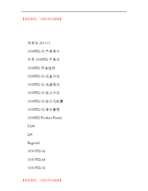
Alcatel_OTN_1830PSS-32产品简介_图文.(精编文档).doc
【最新整理,下载后即可编辑】邢东坡2013.111830PSS-32 产品简介目录 1830PSS 产品线1830PSS 网络结构1830PSS-32 设备介绍1830PSS-32 波道规划1830PSS-32 板卡介绍1830PSS-32 拓扑及配置1830PSS-32 维护管理1830PSS Product FamilyULHLHRegional1830 PSS-361830 PSS-641830 PSS-32Metro1830 PSS-161830 PSS-1Access1830 PSS-41830 PSS Overview Network View from Access to the Core DWDM CoreDWDM MetroC/DWDM Access1830 PSS-11830 PSS-41830 PSS-11830 PSS-41830 PSS-11830 PSS-42.5G/10GLow rate aggregation Cost-efficiency10G/40G/100G FlexibilityAutomation plug & play1830 PSS-32/361830 PSS-361830 PSS-641830 PSS-321830 PSS-321830 PSS-32PSS-1/4: FOADMCost-effective C/DWDMMulti-service GE/TDM aggregation Easy in-band managementRouterIPPSS-36/64: 88 channels DWDM T&ROADM, Multi-degreeOTN Interoperable framing formats Photonic OAM1830 PSS-16OTN/TDM10GE/40GE PSS-32: 88 channels DWDM T&ROADM, Multi-degree Photonic OAMPSS-16: 88 channels DWDM FOADM and ROADM degree-2 Photonic OAM1850 TSS Optical支持 OTN / GbE / TDM 业务板卡C波段全波可调的基于OTN技术的Tunable OTU/可插拔CWDM/DWDM XFPs OTU 通用的客户接口卡 (11GANYRATE,10XANY in 10G,12xGbE in 10G 支持透明传送业务/汇聚传送业务业务分插复用多速率业务接入异种光接入的适配产品特点44/88波道DWDM/8波道 CWDM统一平台2-8方向基于WSS技术的 R/TOADM,具备彩色/无色接口业务上/下提供固定OADM /ROADM /Tunable OADM多种配置点对点,环网,网格网支持2.5G/10G/40G传送光层OAM: Wavelength Tracker 支持异种波长接入先进的网络规划工具(EPT 最优的产品集成度尺寸622mm (H x 439mm (W x 280mm (D1830 PSS-32 针对业务IP化设计的灵活的 xOADM 波分平台1830 PSS-32子架和板卡USER PANELU n i v S l o t U n i v S l o t U n i v S l o t U n i v S l o t U n i v S l o t U n i v S l o t U n i v S l o t U n i v S l o t Upper FanU n i v S l o t U n i v S l o t U n i v S l o t U n i v S l o t U n i v S l o t U n i v S l o t U n i v S l o t U n i v S l o t U n i v S l o t U n i v S l o tU n i v S l o t U n i v S l o t U n i v S l o t U n i v S l o t U n i v S l o t U n i v S l o t U n i v S l o t U n i v S l o t U n i v S l o t U n i v S l o t U n i v S l o t U n i v S l o t U n i v S l o t U n i v S l o t E C电源设备控制器32 x 业务槽位SFD44SFD44OPS C W R 8B L A N KE CA L P H GA H P H G S F C 8S F D 5S F C 4S F C 2P F D C光放WSS FOADM公共板卡External shelf for 44 ch mux/demuxP F D CP F D C E C 11S T A R 111S T G E 1211S T M M 10光波长转发器11D P A R 111D P G E 1211D P M M 10CWDM波道规划(8波100-GHz DWDM波道规划(40/44波DWDM50-GHz DWDM波道规划(80/88波DWDM缩写描述种类尺寸公共板卡EC 设备控制器 1单槽位宽,半高 FAN 风扇 1子架专用槽位安装 PFDCxx电源滤波器 4: x=20, 30, 50, 70单槽位宽,半高 USRPNL 用户接口盘 1子架专用槽位安装放大器A2325A 23dBm高功率高增益 DWDM 放大器1单槽位宽,全高ALPHG 低功率高增益 DWDM放大器 1单槽位宽,全高 AHPHG高功率高增益 DWDM放大器 1单槽位宽,全高 AHPLG高功率低增益DWDM放大器 1单槽位宽,全高光滤波器SFD5x静态滤波器 DWDM 5 波道 8: x=A, B, C, D, E, F, G, HSFD8x静态滤波器 DWDM 8 波道 8: x=A, B, C, DSFD44 44波道光复用解复用器 2 (SFD44和SFD44BSFD40 40波道光复用解复用器 2 (SFD40和SFD40BCWR8/CWR88 8/88 波道无色波长路由器 1SFC8 静态滤波器 CWDM 8 波道 1SFC4x静态滤波器 CWDM 4 波道 2: x=A, BSFC2x静态滤波器 CWDM 2 波道 4: x=A, B, C, D光波长转换器和相应板卡11STAR1 11G 单端口可调任意速率 (1个客户接口 1单槽位宽,半高 11QPA4 11G 四端口可调任意速率 (4个客户接口 1单槽位宽,全高 11STMM10 11G 单端口可调多速率复用板 (10 个通用的客户接口 1单槽位宽,全高 11STGE12 11G 单端口可调 GbE复用板 (12个客户口 1单槽位宽,全高 11DPGE12 11G 双端口可调 GbE复用板(12个客户口 1单槽位宽,全高 43STA1 43G单端口可调任意速率 (1个客户口 1三槽位宽,全高 43STX4 43G单端口可调10G复用板 (4个客户口 1三槽位宽,全高 4DPA4 2.7G双端口多速率复用板 (4个客户口 1单槽位宽,半高 4DPA2 2.7G双端口多速率复用板 (2个客户口 1单槽位宽,半高 112SCA1 112G单端口可调板 (1个客户口 1三槽位宽,全高 112SCX10 112G单端口可调 10G复用板(10个客户口 1三槽位宽,全高 SVAC 单路可调衰耗器板卡 1单槽位宽,半高OPSA 增强型光保护倒换组件 1单槽位宽,半高色散补偿模块DMSMFxxx DCM 单模光纤 (G。
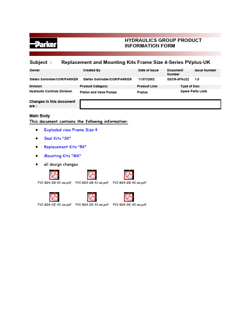
海德拉尔系列产品信息表说明书
<BR>HYDRAULICS GROUP PRODUCTINFORMATION FORM<BR>Subject : Replacement and Mounting Kits Frame Size 4-Series PVplus-UKIssue Number Owner Created By Date of Issue DocumentNumberStefan Schindler/COR/PARKER Stefan Schindler/COR/PARKER11/07/2002SSCR-5FNJ22 1.0Main BodyThis document contains the following information:Exploded view Frame Size 4zSeal Kits "SK"zReplacement Kits "RK"zMounting Kits "MK"zall design changeszPVI-BG4-GB-42-sw.pdf PVI-BG4-GB-41-sw.pdf PVI-BG4-GB-40-sw.pdfPVI-BG4-DE-42-sw.pdf PVI-BG4-DE-41-sw.pdf PVI-BG4-DE-40-sw.pdfExploded view, PV, frame size 4, PV140 - PV180correlation between position numbers and replacement kitspos. No.description page replacement kit 1, 2pump body, end cover--3swash plate, finished6swashplate kit4body seal4seal kit5cradle--6trunnion bearing, HX6trunnion bearing kit7spring washer, servo spring8servo spring kit8servo spring8servo spring kit9connector servo spring6swashplate kit10servo spring plug8servo spring kit11swash plate connector6swashplate kit13tapered / contour sleeve8tapered / contour sleeve 14shaft7shaft unit15piston and slipper, crimped6rotating group, set of pistons 16cylinder block6rotating group17retainer spring, cylinder block6rotating group18pilot cover--20distance washer6rotating group21slipper retainer6rotating group22retainer segment6rotating group23valve plate6valve plate26servo piston sleeve7servo piston sleeve27servo piston7servo piston kit28servo piston cover8displacement adjuster kit 29set screw8displacement limiter kit 30thru drive adaptor10mounting kit, thru drive 31thru drive cover--32air bleed valve8air bleed valve35, 36rotation indicator, name plate--37key7shaft unit38snap ring for shaft7shaft unit39snap ring for bore6rotating group41hexagon socket head cap screw, retainer6rotating group42hexagon socket head cap screw, body6connecting bolt kit43hexagon socket head cap screw, pilot6connecting bolt kit44rivet--45guide pin, servo spring8servo spring kit46locator pin cradle--47locator pin, valve plate6valve plate48locator pin, body6connecting bolt kit50washer, servo piston7servo piston kit51, 56washer, cylinder block6rotating group52washer, shaft7shaft unit53, 54magnet cover for ports, thru drive--55protection plug, drain port--57roller bearing, rear7shaft unit58plug, compensator interface4seal kit59plug, feedback4seal kit60chain link6swashplate kit62roller bearing, front7shaft unit63 - 71o-ring4seal kit72shaft seal4seal kit73self sealing lock nut4, 8seal kit, displacement limiter 75 - 77, 78backup rings, retainer for shaft seal4seal kit79 - 81pipe plug4seal kit82hexagon socket countersunk head cap screw6trunnion bearing kit83hexagon socket head cap screw, cradle--84o-ring4seal kit85hexagon socket head cap screw, thru drive10mounting kit, thru drive 87locator pin, thru drive adaptor10mounting kit, thru drive 90o-ring4seal kit91coupling9mounting kit, coupling 92adaptor for keyed shaft9mounting kit, couplingSK-Seal kitPVBG4PV series, frame size 4, PV140 - PV180N Seals NBRV Seals FPME Seals EPRP Seals FPM, shaft seal PTFE (for case pressure)W Seals NBR, shaft seal PTFE (for water glycole)1Threads: metric, ports: BSPP3Threads: UNC, ports: UNF7Threads: metric, ports: ISO 61498Threads: UNC, ports: ISO 614942Design series 42includes:41body seal, frame size 4581pipe plug VSTI-10x1-OR-A3C ISO 6149 NBR seals NBR 58(1)pipe plug VSTI-10x1-OR-A3C ISO 6149 FPM seals FPM 58(1)pipe plug VSTI-10x1-OR-A3C, ISO 6149 EPR seals EPR 591pipe plug M 27 x 2 ISO 6149, NBR seals NBR 59(1)pipe plug M 27 x 2 ISO 6149, FPM seals FPM 59(1)pipe plug M 27 x 2 ISO 6149, EPR seals EPR 632o-ring 2-010-N552-90; 6,07 x 1,78seals NBR 63(2)o-ring 2-010-V747-75; 6,07 x 1,78seals FPM 63(2)o-ring 2-010-E540-80; 6,07 x 1,78seals EPR 651o-ring 2-136-N552-90; 50,47 x 2,62seals NBR 65(1)o-ring 2-136-V747-75; 50,47 x 2,62seals FPM 65(1)o-ring 2-136-E540-80; 50,47 x 2,62seals EPR 661o-ring 2-036-N552-90; 60,05 x 1,78seals NBR 66(1)o-ring 2-036-V747-75; 60,05 x 1,78seals FPM 66(1)o-ring 2-036-E540-80; 60,05 x 1,78seals EPR 671o-ring 2-157-N552-90; 113,97 x 2,62seals NBR 67(1)o-ring 2-157-V747-75; 113,97 x 2,62seals FPM 67(1)o-ring 2-157-E540-80; 113,97 x 2,62seals EPR 681o-ring 2-140-N552-90; 56,82 x 2,62seals NBR 68(1)o-ring 2-140-V747-75; 56,82 x 2,62seals FPM 68(1)o-ring 2-140-E540-80; 56,82 x 2,62seals EPR 691o-ring 2-153-N552-90; 88,57 x 2,62seals NBR 69(1)o-ring 2-153-V747-75; 88,57 x 2,62seals FPM 69(1)o-ring 2-153-E540-80; 88,57 x 2,62seals EPR 701o-ring 2-145-N552-90; 64,77 x 2,62seals NBR 70(1)o-ring 2-145-V747-75; 64,77 x 2,62seals FPM 70(1)o-ring 2-145-E540-80; 64,77 x 2,62seals EPR 711o-ring 2-035-N552-90; 56,87 x 1,78seals NBR 71(1)o-ring 2-035-V747-75; 56,87 x 1,78seals FPM 71(1)o-ring 2-035-E540-80; 56,87 x 1,78seals EPR 721shaft seal BABSL 0,5 60 x 80 x 7-NBR seals NBR 72(1)shaft seal BABSL 0,5 60 x 80 x 7-FPM seals FPM 72(1)shaft seal PTFE, frame size 4 with EPR o-ring seals EPR, S 72(1)shaft seal PTFE, frame size 4seals P, W 731self sealing nut M 14 x 1,5; SEAL LOCK751back up ring 8-136-N300-90; 51,26 x 2,18seals NBR 75(1)back up ring 8-136-V709-90; 51,26 x 2,18seals FPM 75(1)back up ring 8-136-E652-90; 51,26 x 2,18seals EPR 761back up ring 8-035-N300-90; 57,61 x 1,35seals NBR 76(1)back up ring 8-035-V709-90; 57,61 x 1,35seals FPM 76(1)back up ring 8-035-E652-90; 57,61 x 1,35seals EPR 771back up ring 8-036-N300-90; 60,78 x 1,35seals NBR77(1)back up ring 8-036-V709-90; 60,78 x 1,35seals FPM77(1)back up ring 8-036-E652-90; 60,78 x 1,35seals EPR781J82 x 2,5 DIN 472, retainer for shaft seal791pipe plug VSTI R3/4" ED NBR NBR, thread 1 79(1)pipe plug VSTI R3/4" ED FPM FPM, thread 1 79(1)pipe plug VSTI R3/4" ED EPR EPR, thread 1 79(1)pipe plug 12HP50NS-NBR, 1 1/16-12 UNF NBR, thread 3 79(1)pipe plug 12HP50NS-FPM, 1 1/16-12 UNF FPM, thread 3 79(1)pipe plug 12HP50NS-EPR, 1 1/16-12 UNF EPR, thread 3 79(1)pipe plug VSTI-27 x 2-OR-A3C ISO 6149 NBR NBR, thread 7, 8 79(1)pipe plug VSTI-27 x 2-OR-A3C ISO 6149 FPM FPM, thread 7, 8 79(1)pipe plug VSTI-27 x 2-OR-A3C ISO 6149 EPR EPR, thread 7, 8 801pipe plug VSTI R1/4" ED NBR NBR, thread 1 80(1)pipe plug VSTI R1/4" ED FPM FPM, thread 1 80(1)pipe plug VSTI R1/4" ED EPR EPR, thread 1 80(1)pipe plug 4HP50NS-NBR, 7/16-20 UNF NBR, thread 3 80(1)pipe plug 4HP50NS-FPM, 7/16-20 UNF FPM, thread 3 80(1)pipe plug 4HP50NS-EPR, 7/16-20 UNF EPR, thread 3 80(1)pipe plug VSTI-12 x 1,5-OR-A3C ISO 6149 NBR NBR, thread 7, 8 80(1)pipe plug VSTI-12 x 1,5-OR-A3C ISO 6149 FPM FPM, thread 7, 8 80(1)pipe plug VSTI-12 x 1,5-OR-A3C ISO 6149 EPR EPR, thread 7, 8 811pipe plug VSTI R1" ED NBR NBR, thread 1 81(1)pipe plug VSTI R1" ED FPM FPM, thread 1 81(1)pipe plug VSTI R1" ED EPR EPR, thread 1 81(1)pipe plug 16HP50NS-NBR, 1 5/16-12 UNF NBR, thread 3 81(1)pipe plug 16HP50NS-FPM, 1 5/16-12 UNF FPM, thread 3 81(1)pipe plug 16HP50NS-EPR, 1 5/16-12 UNF EPR, thread 3 81(1)pipe plug VSTI-33 x 2-OR-A3C ISO 6149 NBR NBR, thread 7, 8 81(1)pipe plug VSTI-33 x 2-OR-A3C ISO 6149 FPM FPM, thread 7, 8 81(1)pipe plug VSTI-33 x 2-OR-A3C ISO 6149 EPR EPR, thread 7, 8 841o-ring 2-164-N552-90; 158,42 x 2,62seals NBR84(1)o-ring 2-164-V747-75; 158,42 x 2,62seals FPM84(1)o-ring 2-164-E540-80; 158,42 x 2,62seals EPR841o-ring 2-163-N552-90; 152,07 x 2,62seals NBR84(1)o-ring 2-163-V747-75; 152,07 x 2,62seals FPM84(1)o-ring 2-163-E540-80; 152,07 x 2,62seals EPR841o-ring 2-048-N552-90; 120,37 x 1,78seals NBR84(1)o-ring 2-048-V747-75; 120,37 x 1,78seals FPM84(1)o-ring 2-048-E540-80; 120,37 x 1,78seals EPR841o-ring 2-044-N552-90; 94,97 x 1,78seals NBR84(1)o-ring 2-044-V747-75; 94,97 x 1,78seals FPM84(1)o-ring 2-044-E540-80; 94,97 x 1,78seals EPR841o-ring 2-042-N552-90; 82,27 x 1,78seals NBR84(1)o-ring 2-042-V747-75; 82,27 x 1,78seals FPM84(1)o-ring 2-042-E540-80; 82,27 x 1,78seals EPR841o-ring 2-041-N552-90; 75,92 x 1,78seals NBR84(1)o-ring 2-041-V747-75; 75,92 x 1,78seals FPM84(1)o-ring 2-041-E540-80; 75,92 x 1,78seals EPR901o-ring 2-012-N552-90; 9,25 x 1,78seals NBR90(1)o-ring 2-012-V747-75; 9,25 x 1,78seals FPM90(1)o-ring 2-012-E540-80; 9,25 x 1,78seals EPR2611o-ring 6-346-N552-90; 9,4 x 2,1seals NBR261(1)o-ring 6-346-V747-75; 9,4 x 2,1seals FPM261(1)o-ring 6-346-E540-80; 9,4 x 2,1seals EPRPVBG4PV series, frame size 4, PV140 - PV180VT Connecting bolt kitM Metric versionS SAE/UNC version40Design series 40 - 42includes:424hexagon socket head cap screw M 16 x 75 DIN 912 12.9thread M 42(4)hexagon socket head cap screw 5/8" - 11 UNC x 3", 12.9thread S 434hexagon socket head cap screw M 8 x 20 DIN 912 12.9thread M 43(4)hexagon socket head cap screw Nr. 5/16" - 18 UNC x 3/4", 12.9thread S 482roll pin 8 M6 x 16 DIN 7 St 50KRK-Replacement kitPVBG4PV series, frame size 4, PV140 - PV180GLE Trunnion bearing unit40Design series 40 - 42includes:62trunnion bearing segment HX, frame size 4822hexagon socket countersunk head cap screw M 5 x 10 DIN 7991, RK-Replacement kitPVBG4PV series, frame size 4, PV140 - PV180ROG Rotating group40Design series 40 - 42includes:159piston and slipper, crimped161cylinder block, bimetal171retainer spring, cylinder block204distance element211slipper retainer plate222retainer segment391snap ring for holes, 60 x 2 DIN 472414hexagon socket head cap screw M 8 x 30 DIN 912 12.9, coated511washer, SS 48 x 60 x 3 DIN 988561washer, 44 x 59 x 3RK-Replacement kitPVBG4PV series, frame size 4, PV140 - PV180KOS Piston assembly, set40Design series 40 - 42includes159piston and slipper, crimpedRK-Replacement kitPVBG4PV series, frame size 4, PV140 - PV180SS Valve plateR Clockwise rotationL Counter-clockwise rotation40Design series 40 - 42includes:231valve plate, clockwise rotation, frame size 4rotation R 23(1)valve plate, counterclockwise rotation, frame size 4rotation L 471locator pin 6 M6 x 14 DIN 7 StRK-Replacement kitPVBG4PV series, frame size 4, PV140 - PV180SRS Swashplate unit41Design series 41includes:31swash plate, finished, frame size 491locator for servo spring, frame size 4111swash plate connector frame size 4601chain link, 596 - 111 DIN 8187PVBG4PV series, frame size 4, PV140 - PV180WP Shaft unit, keyedWZ Shaft unit, splinedWQ Shaft unit, keyed, heavy duty SAE onlyWF Shaft unit, splined, heavy duty SAE onlyM Metric versionS SAE/UNC version40Design series 40 - 42includes:141shaft, keyed, metric, frame size 4keyed, metric14(1)shaft, keyed, SAE, frame size 4, heavy duty keyed, SAE, heavy d. 14(1)shaft, keyed, SAE, frame size 4keyed, SAE14(1)shaft, splined, metric, frame size 4splined, metric14(1)shaft, splined, SAE, frame size 4, heavy duty splined, SAE, heavy 14(1)shaft, splined, SAE, frame size 4splined, SAE371key, 14 x 9 x 75 DIN 6885 St keyed, metric37(1)key, 12,7 x 12,7 x 75,5keyed, SAE, heavy d. 37(1)key, 11,1 x 11,1 x 55keyed, SAE382Snap ring for shaft, 60 x 2 DIN 471522washer, PS 60 x 75 x 2 DIN 988571Roller bearing F 204754, INA621Roller bearing NUP - 2212 - EC,RK-Replacement kitPV140PV series, frame size 4, PV140PV180PV series, frame size 4, PV180HE Stroke limit unit, adjustableN Seals NBRV Seals FPME Seals EPR41Design series 41 - 42includes:281servo piston cover291stroke limiter, M 14 x 1,5, displacement 140 cm³/rev size 14029(1)stroke limiter, M 14 x 1,5, displacement 180 cm³/rev size 180701o-ring 2-145-N552-90; 64,77 x 2,62seals NBR70(1)o-ring 2-145-V747-75; 64,77 x 2,62seals FPM70(1)o-ring 2-145-E540-80; 64,77 x 2,62seals EPR731self sealing lock nut, M 14 x 1,5; SEAL LOCKRK-Replacement kitPVBG4PV series, frame size 4, PV140SKS Servo piston kit42Design series 42includes:271servo piston, frame size 4504washer SS 22 x 32 x 2 DIN 988RK-Replacement kitPVBG4PV series, frame size 4, PV140 - PV180RFS Servo spring unit40Design series 40 - 42includes:71spring washer, servo spring, frame size 481servo spring, frame size 4101servo spring cover, frame size 4451Connex LG 22 x 100, roll pinPVBG4PV series, frame size 4, PV140 - PV180 SB Servo piston sleeve N Seals NBR V Seals FPM E Seals EPR42Design series 40 - 42includes:261servo piston sleeve, frame size 4661o-ring 2-036-N552-90; 60,05 x 1,78seals NBR 66(1)o-ring 2-036-V747-75; 60,05 x 1,78seals FPM 66(1)o-ring 2-036-E540-80; 60,05 x 1,78seals EPR 711o-ring 2-035-N552-90; 56,87 x 1,78seals NBR 71(1)o-ring 2-035-V747-75; 56,87 x 1,78seals FPM 71(1)o-ring 2-035-E540-80; 56,87 x 1,78seals EPR 761back up ring 8-035-N300-90; 57,61 x 1,35seals NBR 76(1)back up ring 8-035-V709-90; 57,61 x 1,35seals FPM 76(1)back up ring 8-035-E652-90; 57,61 x 1,35seals EPR 771back up ring 8-036-N300-90; 60,78 x 1,35seals NBR 77(1)back up ring 8-036-V709-90; 60,78 x 1,35seals FPM 77(1)back up ring 8-036-E652-90; 60,78 x 1,35seals EPR32RK-Replacement kitPV000PV series, alle frame sizen EV Air bleed valve N Seals NBR V Seals FPM E Seals EPR40Design series 40 - 42includes:2601body air bleed valve2611o-ring 6-346-N552-90; 9,4 x 2,1seals NBR 261(1)o-ring 6-346-V747-75; 9,4 x 2,1seals FPM 261(1)o-ring 6-346-E540-80; 9,4 x 2,1seals EPR2621spring air bleed valve2631ball Ø 6,35, tungsten carbide, class G202641roll pin, 2 x 10 DIN 148113RK-Spare parts kitPVBG4PV series, frame size 2, PV032 - PV046 KH Feedback / contour sleeve0Feedback sleeve for standard pumpsK M S T U W Y Z 41Design series 41 - 42includes:131Feedback sleeve frame size 413(1)Contour sleeve frame size 4, 18,5 kW horse power code K 13(1)Contour sleeve frame size 4, 22 kW horse power code M 13(1)Contour sleeve frame size 4, 30 kW horse power code S 13(1)Contour sleeve frame size 4, 37 kW horse power code T 13(1)Contour sleeve frame size 4, 45 kW horse power code U 13(1)Contour sleeve frame size 4, 55 kW horse power code W 13(1)Contour sleeve frame size 4, 75 kW horse power code Y 13(1)Contour sleeve frame size 4, 90 kW horse power code ZContour sleeve for horse power compensated pumps, 18,5 kW Contour sleeve for horse power compensated pumps, 22 kW Contour sleeve for horse power compensated pumps, 30 kW Contour sleeve for horse power compensated pumps, 37 kW Contour sleeve for horse power compensated pumps, 45 kW Contour sleeve for horse power compensated pumps, 55 kW Contour sleeve for horse power compensated pumps, 75 kW Contour sleeve for horse power compensated pumps, 90 kWPos.Qty Ordering code Description Remark MK-Mounting kit: coupling for thru drive pumpPVBG4PV series , frame size 4, PV140 - PV180K01Second pump: metric splined shaft N25 x 1,5 x 15 DIN 5480K02Second pump: metric splined shaft N32 x 1,5 x 20 DIN 5480K03Second pump: metric splined shaft N40 x 1,5 x 25 DIN 5480K04Second pump: metric splined shaft N50 x 2 x 24 DIN 5480K11Second pump: SAE splined shaft 9T16/32DP flat root side fitK12Second pump: SAE splined shaft 11T16/32DP flat root side fitK13Second pump: SAE splined shaft 13T16/32DP flat root side fitK14Second pump: SAE splined shaft 15T16/32DP flat root side fitK15Second pump: SAE splined shaft 14T12/24DP flat root side fitK16Second pump: SAE splined shaft 17T12/24DP flat root side fitK17Second pump: SAE splined shaft 13T8/16DP flat root side fitK18Second pump: SAE splined shaft 15T8/16DP flat root side fitK20Second pump: metric keyed shaft Ø 12 mmK21Second pump: metric keyed shaft Ø 16 mmK22Second pump: metric keyed shaft Ø 18 mm40Design series 40 - 42includes:91(1)coupling, metric, N50 x 2 x 24 DIN 5480shaft K04 91(1)coupling, metric, N40 x 1,5 x 25 DIN 5480shaft K0391(1)coupling, metric, N32 x 1,5 x 20 DIN 5480shaft K02, K20, K21, K2291(1)coupling, metric, N25 x 1,5 x 15 DIN 5480shaft K01 91(1)coupling, SAE, 15T8/16DP, flat root, side fit shaft K18 91(1)coupling, SAE, 13T8/16DP, flat root, side fit shaft K17 91(1)coupling, SAE, 17T12/24DP, flat root, side fit shaft K16 91(1)coupling, SAE, 14T12/24DP, flat root, side fit shaft K15 91(1)coupling, SAE, 15T16/32DP, flat root, side fit shaft K14 91(1)coupling, SAE, 13T16/32DP, flat root, side fit shaft K13 91(1)coupling, SAE, 11T16/32DP, flat root, side fit shaft K12 91(1)coupling, SAE, 9T16/32DP, flat root, side fit shaft K11 92(1)adaptor for keyed shaft Ø 18 (also needed: pos 91, shaft K02)shaft K22 92(1)adaptor for keyed shaft Ø 16 (also needed: pos 91, shaft K02)shaft K21 92(1)adaptor for keyed shaft Ø 12 (also needed: pos 91, shaft K02)shaft K20Pos.Qty Ordering codeDescriptionRemarkMK-Mounting kit: adaptor for thru drive pump PVBG4PV series , frame size 4, PV140 - PV180 A For thru drive pump: SAE A, Ø 82,55 B For thru drive pump: SAE B, Ø 101,6 C For thru drive pump: SAE C, Ø 127 D For thru drive pump: SAE D, Ø 152,4 H For thru drive pump: metric Ø 80 J For thru drive pump: metric Ø 100 K For thru drive pump: metric Ø 125 L For thru drive pump: metric Ø 160 M Metric screws S UNC screws N Seals NBR V Seals FPM E Seals EPR40Design series 40 - 42includes:301thru drive adaptor SAE A, Ø 82,55, metric screws interf. A, screws: M 30(1)thru drive adaptor SAE A, Ø 82,55, UNC screws interf. A, screws: S 30(1)thru drive adaptor SAE B, Ø 101,6, metric screws interf. B, screws: M 30(1)thru drive adaptor SAE B, Ø 101,6, UNC screws interf. B, screws: S 30(1)thru drive adaptor SAE C, Ø 127, metric screws interf. C, screws: M 30(1)thru drive adaptor SAE C, Ø 127, UNC screws interf. C, screws: S 30(1)thru drive adaptor SAE D, Ø 152,4, metric screws interf. D, screws: M 30(1)thru drive adaptor SAE D, Ø 152,4, UNC screws interf. D, screws: S 30(1)thru drive adaptor: metric Ø 80, metric screws interf. H, screws: M 30(1)thru drive adaptor: metric Ø 80, UNC screws interf. H, screws: S 30(1)thru drive adaptor: metric Ø 100, metric screws interf. J, screws: M 30(1)thru drive adaptor: metric Ø 100, UNC screws interf. J, screws: S 30(1)thru drive adaptor: metric Ø 125, metric screws interf. K, screws: M 30(1)thru drive adaptor: metric Ø 125, UNC screws interf. K, screws: S 30(1)thru drive adaptor: metric Ø 160, metric screws interf. L, screws: M 30(1)thru drive adaptor: metric Ø 160, UNC screws interf. L, screws: S 311cover plate, thru driveoption T 691o-ring 2-153-N552-90; 88,57 x 2,62seals NBR 69(1)o-ring 2-153-V747-75; 88,57 x 2,62seals FPM 69(1)o-ring 2-153-E540-80; 88,57 x 2,62seals EPR 841o-ring 2-041-N552-90; 75,92 x 1,78interf. H, NBR 84(1)o-ring 2-041-V747-75; 75,92 x 1,78interf. H, FPM 84(1)o-ring 2-041-E540-80; 75,92 x 1,78interf. H, EPR 841o-ring 2-042-N552-90; 82,27 x 1,78interf. A, NBR 84(1)o-ring 2-042-V747-75; 82,27 x 1,78interf. A, FPM 84(1)o-ring 2-042-E540-80; 82,27 x 1,78interf. A, EPR 841o-ring 2-044-N552-90; 94,97 x 1,78interf. B, J, NBR 84(1)o-ring 2-044-V747-75; 94,97 x 1,78interf. B, J, FPM 84(1)o-ring 2-044-E540-80; 94,97 x 1,78interf. B, J, EPR 841o-ring 2-048-N552-90; 120,37 x 1,78interf. C, K, NBR 84(1)o-ring 2-048-V747-75; 120,37 x 1,78interf. C, K, FPM 84(1)o-ring 2-048-E540-80; 120,37 x 1,78interf. C, K, EPR 84(1)o-ring 2-163-N552-90; 152,07 x 2,62interf. D, NBR 84(1)o-ring 2-163-V747-75; 152,07 x 2,62interf. D, FPM 84(1)o-ring 2-163-E540-80; 152,07 x 2,62interf. D, EPR 84(1)o-ring 2-164-N552-90; 158,42 x 2,62interf. L, NBR 84(1)o-ring 2-164-V747-75; 158,42 x 2,62interf. L, FPM 84(1)o-ring 2-164-E540-80; 158,42 x 2,62interf. L, EPR 854hexagon socket head cap screw M 12 x 30 DIN 912 12.9screws: M 85(4)hexagon socket head cap screw 1/2" - 13 UNC x 1 1/4", 12.9screws: S872locator pin 8 M6 x 16 DIN 7not for option T 972hexagon socket head cap screw, M10 x 20 DIN 912 12.9option T, screws: M 97(2)hexagon socket head cap screw 3/8" - 16 UNC x 3/4", 12.9option T, screws: SScrews, washers etc. needed to fix the second pump to the adaptor are not included in the kit。
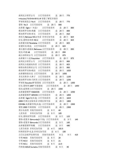
罗密欧丘吉尔铝管雪茄
玻利瓦尔铝管2号古巴雪茄系列盒25只775++koukou7-0-5-6-4-9-5-1-9客服了解更多报价罗密欧展览会No.4 古巴雪茄系列盒25只775蒙特No.3 古巴雪茄系列盒25只800高希霸Siglo I(木盒)古巴雪茄系列盒25只800维加斯罗宾纳-典藏古巴雪茄系列盒25只800维加斯罗宾纳-密友古巴雪茄系列盒25只810唐迭戈Belicoso NO.2鱼雷多米尼加雪茄盒25只825好友.蒙特雷贵族NO.2 古巴雪茄系列盒25只825高希霸宾丽Panetelas 古巴雪茄系列盒25只825雷蒙阿龙-特选古巴雪茄系列盒25只825桑丘潘沙-彪丽高Belicosos 古巴雪茄系列盒25只850优民-玛瑙46 古巴雪茄系列盒25只850威古洛特制2号古巴雪茄系列盒25只875高希霸吉士途Exquisitos 古巴雪茄系列盒25只875波利瓦尔铝管1号古巴雪茄系列盒25只900波利瓦尔彪丽高鱼雷古巴雪茄系列盒25只925帕特加斯喜维亚2号古巴雪茄系列盒25只950维加斯罗宾纳-极品古巴雪茄系列盒25只1025高希霸特级皇冠古巴雪茄系列盒25只1050圣克里斯多-大鼻子古巴雪茄系列盒25只1150维加斯罗宾纳-当阿里古巴雪茄系列盒25只1250罗密欧Escudos 07限量版古巴雪茄系列盒25只1450好友.蒙特利2007年限量版古巴雪茄系列盒25只1450 优民-温斯顿古巴雪茄系列盒25只1500高希霸蒙都罗MAGICOS 古巴雪茄系列盒25只1550高希霸蒙都罗GENIOS 古巴雪茄系列盒25只1650高希霸SigloⅥ(木盒) 古巴雪茄系列盒25只18252008经典纪念版鱼雷洪都拉斯雪茄盒25只1900 COHIBA高希霸导师(木盒) 古巴雪茄系列盒25只2300蒙特2003年限量版古巴雪茄系列盒25只2300黑后水晶筒其他雪茄系列盒3只40七星鱼雷多米尼加雪茄盒3只105好友.蒙特雷罗伯图古巴雪茄系列盒3只115蒙特-爱蒙多Edmundo(3只装) 古巴雪茄系列盒3只145 蒙特-爱蒙多Edmundo 古巴雪茄系列盒3只145高希霸蒙都罗典藏古巴雪茄系列盒3只490七星告郎拿多米尼加雪茄盒4只102.5科斯塔雷伊-礼盒多米尼加雪茄盒4只150古巴纪念版罗伯图雪茄其他雪茄系列5支5只415 亨利NO.8 其他雪茄系列盒5只20亨利NO.3 其他雪茄系列盒5只21亨利NO.1 其他雪茄系列盒5只22.5丹纳曼-GOLD Sumatra 其他雪茄系列盒5只30帕塔加斯(中号) 古巴雪茄系列盒5只47.5罗密欧(中) 古巴雪茄系列盒5只47.5JOSE L.PIEDRA比雅达古巴雪茄系列盒5只70奥利华Oliva Serie G 洪都拉斯雪茄盒5只110好友.蒙特雷-代表古巴雪茄系列盒5只130库阿巴Tradicionales 古巴雪茄系列盒5只150罗密欧Petit Julieta 古巴雪茄系列盒5只160高希霸SigloⅢ(5只) 古巴雪茄系列盒5只225蒙森诺(铁合) 多米尼加雪茄盒6只55罗密欧丘吉尔铝管古巴雪茄系列盒6只390雪茄尺度展示牌NO.1 其他雪茄系列盒7只190高希霸SigloⅢ古巴雪茄系列25只个1125季诺ZINO白金权杖(12支装) 多米尼加雪茄12支罐790蒙特俱乐部Montecristo-Club 古巴雪茄系列50支罐225高希霸COHIBA迷你50支/铁罐迷你小雪茄50支罐225无嘴咖啡迷你(特选) 荷兰雪茄系列10支盒14嘉辉咖啡滤嘴荷兰雪茄系列10支盒15俱乐部香草其他雪茄系列10支盒15特香小金豹荷兰雪茄系列10支盒17.5罗密欧迷你(10支)迷你小雪茄10支盒36季诺迷你迷你小雪茄10支盒37.5麦克纽杜-黄金吉士图Macanudo Gold Label A 多米尼加雪茄10支盒80 Zapata夏帕塔2号洪都拉斯雪茄10支盒225Zapata夏帕塔鱼雷洪都拉斯雪茄10支盒240Miró米洛罗伯图洪都拉斯雪茄10支盒240唐托马斯-Don Tomas Clasico Presidente 洪都拉斯雪茄10支盒240拉菲冈沙雷斯-巨人多米尼加雪茄10支盒390罗密欧&朱丽叶-短丘吉尔古巴雪茄系列10支盒4652010典藏纪念版爱梦多古巴雪茄系列10支盒840季诺白金皇冠铝管雪茄(10支装) 多米尼加雪茄10支盒1525高希霸Cohiba Behike 贝伊可古巴雪茄系列10支盒2600哈利Meharis甜味雪茄荷兰雪茄系列10只盒12.5无嘴咖啡迷你(10只)荷兰雪茄系列10只盒14奶油大咖啡荷兰雪茄系列10只盒15咖啡大金豹荷兰雪茄系列10只盒17.5特选小金豹荷兰雪茄系列10只盒17.5香草小金豹荷兰雪茄系列10只盒17.5咖啡小金豹荷兰雪茄系列10只盒17.5茉丝迷你其他雪茄系列10只盒17.5。
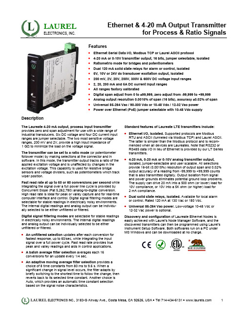
拉雷尔电子有限公司产品说明书
LAUREL ELECTRONICS, INC.Ethernet & 4-20 mA Output Transmitterfor Process & Ratio SignalsFeatures•Ethernet Serial Data I/O, Modbus TCP or Laurel ASCII protocol•4-20 mA or 0-10V transmitter output, 16 bits, jumper selectable, isolated•Ratiometric mode for bridges and potentiometers•Dual 120 mA solid state relays for alarm or control, isolated•5V, 10V or 24V dc transducer excitation output, isolated•200 mV, 2V, 20V, 200V, 300V & 600V DC voltage input ranges•2, 20, 200 mA and 5A DC current input ranges•All ranges factory calibrated•Digital span adjust from 0 to ±99,999, zero adjust from -99,999 to +99,999•Analog output resolution 0.0015% of span (16 bits), accuracy ±0.02% of span•Universal 85-264 Vac / 90-300 Vdc or 10-48 Vdc / 12-32 Vac power•Power over Ethernet (PoE) jumper selectable with 10-48 Vdc supply DescriptionThe Laureate 4-20 mA output, process input transmitter provides zero and span adjustment for use with a wide range of industrial transducers. Six DC voltage and four DC current input ranges are jumper selectable. The two most sensitive voltage ranges, 200 mV and 2V, provide a high input impedance of1 GΩ to minimize the load on the voltage signal.The transmitter can be set to a ratio mode (or potentiometer follower mode) by making selections at the connector and in software. In this mode, the transmitter output tracks a ratio of the applied excitation voltage and is unaffected by changes in the excitation voltage. This capability is used for resistive bridge sensors and voltage dividers, such as potentiometers which track wiper position.Fast read rate at up to 50 or 60 conversions per second while integrating the signal over a full power line cycle is provided by Concurrent Slope (Pat 5,262,780) analog-to-digital conversion. High read rate is ideal for peak or valley capture and for real-time computer interface and control. Digital signal filtering modes are selectable for stable readings in electrically noisy environments. The internal digital readings and analog output can be individu-ally selected to be either unfiltered or filtered.Digital signal filtering modes are selectable for stable readings in electrically noisy environments. The internal digital readings and analog output can be individually selected to be either unfiltered or filtered.•An unfiltered selection updates after each conversion for fastest response, up to 60/sec, while integrating the inputsignal over a full power cycle. Fast read rate provides truepeak and valley readings and aids in control applications. • A batch average filter selection averages each 16 conversions for an update every 1/4 sec.•An adaptive moving average filter selection provides a choice of 8 time constants from 80 ms to 9.6 s. When asignificant change in signal level occurs, the filter adapts by briefly switching to the shortest time to follow the change, then reverts back to its selected time constant. Another choice is Auto, which provides an automatic time constant selectionbased on the signal noise characteristics.Standard features of Laureate LTE transmitters include:•Ethernet I/O, isolated. Supported protocols are ModbusRTU and ASCII (tunneled via Modbus TCP) and Laurel ASCII.The latter is simpler than the Modbus protocol and is recom-mended when all devices are Laureates. Note that RS232 or RS485 data I/O in lieu of Ethernet is provided by our LT Series transmitters.•4-20 mA, 0-20 mA or 0-10V analog transmitter output, isolated, jumper-selectable and user scalable. All selections provide 16-bit (0.0015%) resolution of output span and 0.02% output accuracy of a reading from -99,999 to +99,999 counts that is also transmitted digitally. Output isolation from signal and power grounds eliminates potential ground loop problems.The supply can drive 20 mA into a 500 ohm (or lower) load for 10V compliance, or 10V into a 5K ohm (or higher) load for2 mA compliance.•Dual solid state relays, isolated. Available for local alarm or control. Rated 120 mA at 130 Vac or 180 Vdc.•Universal 85-264 Vac power. Low-voltage 10-48 Vdc or 12-32 Vac power is optional.Discovery and configuration of Laureate Ethernet Nodes is easily achieved with Laurel's Node Manager Software, and the discovered transmitters can then be programmed using Laurel's Instrument Setup Software. Both softwares run on a PC under MS Windows and can be downloaded at no charge.SpecificationsAnalog Input Range Resolution Accuracy Input OhmsDC Voltage ± 200.00 mV± 2.0000 V± 20.000 V± 200.00 V± 600.0 V10 µV100 µV1 mV10 mV100 mV± 0.01% FS± 2 counts1 GΩ1 GΩ10 MΩ10 MΩ10 MΩDC Current ± 2.0000 mA± 20.000 mA± 200.00 mA0.1 µA1 µA10 µA± 0.01% FS± 2 counts100 Ω10 Ω1 Ω ± 5.000 A 1 mA± 0.1% FS± 2 counts0.01 ΩInput Resolution Update Rate, Max Max applied voltage Over-current protection 16 bits (65,536 steps)50/sec at 50 Hz, 60/sec at 60 Hz600 Vac for 20, 200 & 600 V ranges, 125 Vac other ranges 25x for 2 mA, 8x for 20 mA, 2.5x for 200 mA, 1x for 5 AAnalog Output (standard)Output Levels Compliance, 4-20 mA Compliance, 0-10V Output Resolution Output Accuracy Output Isolation Step response time 0-20 mA or 0-10 Vdc (selectable)10V (0-500Ω load)2 mA (5 kΩ load)16 bits (65,536 steps)0.02% of output span plus conversion accuracy 250V rms working, 2.3 kV rms per 1 minute test 50 msDual Relay Output (standard)Relay Type Load Rating Two solid state relays, SPST, normally open, Form A 120 mA at 140 Vac or 180 VdcTransducer Excitation Output (standard)Output Levels Output Isolation 5V@100 mA, 10V@120 mA, 24V@50 mA (jumper selectable) 50V from signal groundSerial Data Output (standard)TypeData RatesOutput Isolation Serial Protocols Modbus Compliance Digital Addresses 10/100Base-T Ethernet per IEEE 802.3300, 600, 1200, 2400, 4800, 9600, 19200 baud250V rms working, 2.3 kV rms per 1 min testModbus TCP, Modbus RTU, Modbus ASCII, Laurel ASCII Modbus over Serial Line Specification V1.0 (2002)247 for Modbus, 31 for Laurel ASCIIPower InputStandard Power Low Power Option Power Frequency Power Isolation Power Consumption 85-264 Vac or 90-300 Vdc10-48 Vdc or 12-32 VacDC or 47-63 Hz250V rms working, 2.3 kV rms per 1 min test 2W typical, 3W with max excitation outputMechanicalDimensions MountingElectrical Connections 129 x 104 x 22.5 mm case35 mm rail per DIN EN 50022 Plug-in screw-clamp connectorsEnvironmental Operating TemperatureStorage Temperature Relative Humidity Cooling Required0°C to 55°C-40°C to 85°C95% at 40°C, non-condensingMount transmitters with ventilation holes at top and bottom. Leave 6 mm (1/4") between transmitters, or force air with a fan.PinoutMechanicalPotentiometer Follower ApplicationIn potentiometric (or potentiometer follower) appli-cations, the signal from a sliding contact voltage divider can be converted to engineering units such as position, level or percentage. By operating in a ratiometric mode, the transmitter removes any effects caused by variations in the excitation supply.For use with a 1 kΩ potentiometer, the recommend-ed applied excitation voltage is 10V. A 2 kΩ resistor should be placed in series with the excitation output and excitation return leads. This will allow the trans-mitter's 2V scale with a high input impedance of 1 GΩ to be used.Ordering GuideCreate a model a model number in this format: LTE20PTransmitter Type LTE Laureate 4-20 mA & Ethernet TransmitterMain Board2 Standard Main Board4 Extended Main BoardNote: Extended allows custom curve linearization and rate from successive readings.Power0 Isolated 85-264 Vac or 90-300 Vdc1 Isolated 12-32 Vac or 10-48 VdcSignal Input Process Signals (e.g., 4-20 mA, 0-5V)P Field scalable. Default scaling is 0-200V in = 4-20 mA outP1 Custom Scaling. Specify min input, min output; max input, max outputNote: The same DC signal conditioner can be user configured for process, strain orpotentiometer follower signals, as well as DC Volts or DC Amps. It is precalibrated inEEPROM for all DC Volt and DC Amp ranges listed for DC transmitters.。
LA1824资料
Block Diagram
FM Ant B.P.F
24
23
22
21
20
GND2 FM
RF
VCC2
FM OSC
FM MIX
+
19
18
TRIG
ST SW
+
+
R-OUT
L-OUT
AM FM
MN ST
17
16
DECODER
VCO
FF
15
14
PHASE COMP
FF
FF
PILOT DET
13 DET
LA1824
Overview
PackageБайду номын сангаасDimensions
The LA1824 is a single-chip tuner IC that incorporates FM/AM and MPX circuits. The built-in MPX-VCO allows this IC to be adjustment free and to require no external components.
AM MIX
AM
RF
AM
REG
OSC
VCC1
GND1
S-METER
DET
AGC
TUN
ST
LED
LED
FM IF
AM-IF
1
2
3
4
5
6
7
8
9
10
11
12
AM Ant +
AM / FM TUN
FM ST
10.7MHz +
LA1800中文资料
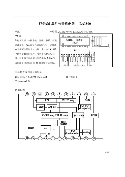
1/10FM/AM 单片收音机电路 LA1800概述 外形图 LA1800 为单片 FM/AM 收音机电路,FM 部分包含混频,本振中放,鉴频,静噪,低通滤波器等;AM 部分包括高放检波,此外还有音频驱动级和功放电路,用一块LA1800电路和少数外围元件,可制作完整的收音机。
该电路工作电源电压范围为 2.5V~5V 。
该电路采用密间距的 22 脚双列直插封装。
主要特点 外接元器件少;功耗低, 5.6mA/FM,3.2mA/AM ; 工作电压低,Vccmin=2.5V 。
功能框图222145 67891518 11power FM AM changeover post ampmuting FM discriminatorphase osc mixerAM RF amp FM IF ampAM detAGCFM IF ampLPF VccGND 192013217 1610141312shifter引出端功能极限值(无特殊说明,Ta=25℃)电参数2/102.直流参数(无特殊说明,Ta=25℃,Vcc=3V,见直流测试图)3/10推荐工作条件(无特殊说明,Ta=25℃)单位:电阻:Ω,电容:F4/10AC测试图单位:电阻:Ω,电容:F应用图图1 单位:电阻:Ώ 电容: F5/10L1 HH-40947 MitsumiT1 HW-40217 MitsumiT2 HW-40194 MitsumiT3 HW-50005 Mitsumi B. P. F .SNY-074-2005 Sumida单位:电阻:Ω,电容:F6/10特性曲线7/108/109/1010/10。
草地贪夜蛾识别及应急防治技术挂图

草地贪夜蛾识别与应急防治技术挂图草地贪夜蛾起源于美洲热带和亚热带地区,广泛分布于美洲大陆,具有适生区域广、迁飞速度快、繁殖能力强、防控难度大的特点。
2018 年在非洲造成高达30 亿美元的经济损失,是联合国粮食及农业组织(FAO)全球预警的重要农业害虫。
2019 年 1 月13 日确认传入我国省,截至 5 月10 日已在我国13 个省份发现。
专家分析预测,草地贪夜蛾将从我国华南玉米区向黄淮海夏玉米主产区及西北、东北玉米主产区等地蔓延,有可能形成局部虫灾。
一、形态特征成虫:翅展32 ~40m m , 前翅深棕色,后翅白色,边缘有窄褐色带。
雌蛾前翅呈灰褐色或灰色棕色杂色,具环形纹和肾形纹,轮廓线黄褐色;雄蛾前翅灰棕色,翅顶角向各具一大白斑,环状纹后侧各具一浅色带自翅外缘至中室,肾形纹侧各具一白色楔形纹。
幼虫:一般有 6 个龄期,体长 1 ~45m m , 体色有浅黄、浅绿、褐色等多种, 最为典型的识别特征是末端腹节背面有 4 个呈正形排列的黑点,三龄后头部可见的倒Y 形纹。
卵:通常100 ~200 粒堆积成块状,多由白色鳞毛覆盖,初产时为浅绿或白色,孵化前渐变为棕色。
卵粒直径0.4m m , 卵高0.3m m。
卵多产于叶片正面,玉米喇叭口期多见于近喇叭口处。
适宜温度下,2 ~3d 孵化。
蛹:被蛹,体长15~17m m,体宽 4.5m m , 化蛹初期体色淡绿色,逐渐变为红棕及黑褐色。
常在2 ~8c m 深的土壤中化蛹,有时也在果穗或叶腋处化蛹。
二、发生规律与田间为害状草地贪夜蛾无滞育现象,适宜发育温度广,为11 ~30℃,在28℃条件下,30d 左右即可完成 1 个世代。
雌、雄虫均可多次交配,单头雌虫可产卵块10 块以上,卵量约 1 500 粒。
在玉米上,一至三龄幼虫通常隐藏在心叶、叶鞘等部位取食,形成半透明薄膜“窗”;低龄幼虫还会吐丝,借助风扩散转移到边的植株上继续为害;四至六龄幼虫对玉米的为害更为重,取食叶片后形成不规则的长形洞,可将整株玉米的叶片取食光,也会钻蛀心叶、未抽出的雄穗及幼嫩雌穗,影响叶片和果穗的正常发育。
TEA1832_2015_webina

保护时安全重启 保护时芯片锁定
TEA1832(L) 芯片的特色
高性能的开关电源控制芯片,适宜要求低成本的应用 空载下Pin < 55mW (符合 CoC tier2 75mW 规格) 较宽的Vcc范围,最大至36V,较低的UVLO : 10.5V (这样可使用小型的 Vcc 电容) 在启动和重启时电源电流很低的 (典型值为10 µA) 在正常工作时的电源电流也较低 (空载下典型值为0.58mA) Fmax = 130kHz (电源在峰值功率下),有峰值电流失控保护 打嗝模式时Vcc电压降低, (在负载变动期间保持Vcc 在 UVLO之上, 可允许使用较小容量的Vcc电容) 最大占空比增加到89% 软启动在IC内部集成 (~3.5msec)
1慢速重启时间
22
(慢) 重启动保护 (1的重启动: - 内部电流源快速放电Vcc至 (典型值2.5mA ) UVLO - 启动电路缓慢充电 Vcc至21.5V (Vstartup) (正常的启动时序) 延迟时间取决于: 输入电压 (低输入电压下延迟时间更长) 启动电路 VCC 电容的容量 对于OPP,一个Vcc充电周期时间太短不能限制输入功率. 为延长重启动时间, 特意用了三个放电 / 充电周期. OPP 重启动 其它的重启动 →慢速重启动(3循环周期, 1 ~ 2.5 s) → 正常的重启动 (1个放电/充电循环, 0.3 ~ 0.75 s)
6
TEA1832在典型的45W应用原理图 (19.5V/2.3A)
7
TEA1832在典型的65W应用原理图(19.5V/3.34A)
8
不同后缀的TEA1832的差异
功能 TEA1832TS (重启) 30 ms 慢速重启1 重启 锁定 锁定 锁定 重启 重启 TEA1832LTS (锁定) 180 ms 锁定 锁定 锁定 锁定 锁定 重启 重启
阿拉卡尔漏油技术法兰斯公司A300油产品说明书
MATERIAL SAFETY DATA SHEET: A3001. PRODUCT: SOME SUBSTANCE OR PREPARATION OF THE SOCIETY:Product name: A300 OIL- Commercial use: vacuum pump lubricantSupplier: ALCATEL VACUUM TECHNOLOGY FRANCEdeBROGNYavenue982069BP74009 ANNECY CEDEXFRANCETelephone: (33) 4 50 65 77 77Fax:(33) 4 50 65 77 89Email:Jean-Loup.MONBEIG@adixenPerson to contact: AVTF Quality ManagerEmergency telephone number: (33) 4 50 65 77 77The time schedule: 8 a m to 12 a m and 2 p m to 5 p m2. COMPOSITION/INGREDIENTS:GENERIC NAME: 100% Solvent refined technical white petroleum oil and additives CHEMICAL FORMULA: (CH2)n 20 =< n =< 40HAZARDOUS INGREDIENTS: NoneCas Number 8042-47-53. HAZARDS IDENTIFICATION:POSSIBLE ENTRY ROUTES: Ingestion, inhalation of oil mistsThis product is not classified as hazardous.ACUTE EFFECTS: Exposure to oils mists may cause nausea and eye.Detailed studies have not been made, but material is not expected to be dermatitic or a sensitizer.CHRONIC EFFECTS: Unknown.4. FIRST AID MEASURES:SKIN: Wash with soap and water.EYES: Flush with water. Contact a physician!INGESTION: If swallowed, do not induce vomiting.Contact a physician. Small amounts in mouth may be washed out.MATERIAL SAFETY DATA SHEET: A3005. FIRE FIGHTING MEASURES:FLASH POINT: >243° CMETHOD USED: Cleveland Open CupEXPLOSIVE LIMITS LOWER: Unknown UPPER: UnknownEXTINGUISHING MEDIA: Water fog, chemical foam or carbon dioxide. NFPA Class III B Material.SPECIAL FIREFIGHTING PROCEDURES: Wear breathing gear when fighting fires in enclosed spaces; incomplete combustion of this material produces carbon monoxide!UNUSUAL FIRE AND/OR EXPLOSION HAZARDS: None6. ACCIDENTAL RELEASE MEASURES:PROCEDURE TO BE FOLLOWED IN EVENT OF RELEASE:Small spills may be wiped up with a rag.Large spills should be picked up immediately with an absorbent.7. STORAGE AND HANDLING:HANDLING: None knownSTORAGE: None known8. EXPOSURE CONTROLS / PERSONAL PROTECTION:ENGINEERING CONTROL MEASURES: None requiredRESPIRATORY PROTECTION: See notes on ventilation below.PROTECTIVE GLOVES: Yes - made of oil-impermeable rubberSAFETY GLASSES/GOGGLES: Yes - glasses should have side shieldsOTHER PROTECTIVE EQUIPMENT: None should be required under normal use.9. PHYSICAL AND CHEMICAL PROPERTIES:PHYSICAL STATE: LiquidVAPOR PRESSURE: < .0001 Torr @ 25CBOILING POINT: >300° CEVAPORATION RATE (ether = 1): NilVAPOR DENSITY: approximately 14WT % VOLATILES: NilSPECIFIC GRAVITY: 0.86VISCOSITY: 56 cst @ 40 CSOLUBILITY IN WATER: NilAPPEARANCE: transparent, colorless, viscous liquid with a faint petroleum odor.MATERIAL SAFETY DATA SHEET: A30010. STABILITY AND REACTIVITY:STABILITY: Material is stableCONDITIONS TO AVOID: Continuous exposure to temperatures > 200 °C INCOMPATIBILITY (MATERIALS TO AVOID): Strong oxidizersHAZARDOUS DECOMPOSITION PRODUCTS: Incomplete combustion may produce carbon monoxide.11. TOXICOLOGICAL INFORMATION:ACUTE ORAL LD50 (MG/KG): None knownACUTE DERMAL LD50: NoneACUTE INHALATION: US Gov't 8 hr TWA limit for exposure to oil mists is 5 mg per cubic meter12. ECOLOGICAL INFORMATION:ENVIRONMENTAL: When used and/or disposed of as indicated, no adverse environmental effects are foreseen.MOBILITY: Non-volatile and insoluble in water.DEGRADABILITY: Slowly biodegradable in aerobic conditions.13. DISPOSAL CONSIDERATIONS:Product and packaging must be disposed of in accordance with Federal, and local regulations.Material may be returned for reclamation14. TRANSPORT CLASSIFICATION:Not classified as hazardous for transport by air, sea or road.15 REGULATORY INFORMATION:NoneMATERIAL SAFETY DATA SHEET: A30016. OTHER INFORMATION:NFPA RATINGFLAMMABILITY 1HEALTHHAZARDREACTIVITY 0SPECIALNONEHAZARDGENERAL CONSIDERATIONS:This sheet completes the technical user manual but does not replace it. The information that it contains is based on our knowledge concerning the product in question, on the date of edition of this sheet, and is given in good faith. Users should also pay attention to the risks which may be involved when a product is used for purposes other than that for which it was originally intended.No guarantees can be given on the accuracy of the information contained in this sheet. The sheet, given to our customers in good faith in the sole aim of informing and helping them in their research, cannot be considered to provide an absolute or implicit guarantee related to its use. Consequently, ALCATEL VACUUM TECHNOLOGY FRANCE or ALCATEL subsidiaries cannot be held responsible for damage of any type related to the publication of this document. Similarly, none of the information it contains should be interpreted as an authorisation or recommendation for the use of products which would cause an infringement of patent rights.。
惠尔登工程有限公司 Pioneer 系列 LED 平行光源 罗玛巴 车顶挂载说明书

©2017 Whelen Engineering Company Inc.Form No.14A66 (033017)A u t o m o t i v e : Installation Guide:Pioneer™ Series LED FloodlightRosenbauer® Brow MountFor warranty information regarding this product, visit /warranty51 Winthrop RoadChester, Connecticut 06412-0684Phone: (860) 526-9504Internet: Salese-mail:*******************CustomerServicee-mail:*******************®ENGINEERING COMPANY INC.•Proper installation of this product requires the installer to have a good understanding of automotive electronics, systems and procedures.•Whelen Engineering requires the use of waterproof butt splices and/or connectors if that connector could be exposed to moisture.•Any holes, either created or utilized by this product, should be made both air- and watertight using a sealant recommended by your vehicle manufacturer.•Failure to use specified installation parts and/or hardware will void the product warranty.•If mounting this product requires drilling holes, the installer MUST be sure that no vehicle components or other vital parts could be damaged by the drilling process. Check both sides of the mounting surface before drilling begins. Also de-burr the holes and remove any metal shards or remnants. Install grommets into all wire passage holes.•If this manual states that this product may be mounted with suction cups, magnets, tape or Velcro®, clean the mounting surface with a 50/50 mix of isopropyl alcohol and water and dry thoroughly.•Do not install this product or route any wires in the deployment area of your air bag. Equipment mounted or located in the air bag deployment area will damage or reduce the effectiveness of the air bag, or become a projectile that could cause serious personal injury or death. Refer to your vehicle owner’s manual for the air bag deployment area. The User/Installer assumes full responsibility to determine proper mounting location, based on providing ultimate safety to all passengers inside the vehicle.•For this product to operate at optimum efficiency, a good electrical connection to chassis ground must be made. The recommendedprocedure requires the product ground wire to be connected directly to the NEGATIVE (-) battery post (this does not include products that use cigar power cords).•If this product uses a remote device for activation or control, make sure that this device is located in an area that allows both the vehicle and the device to be operated safely in any driving condition.•Do not attempt to activate or control this device in a hazardous driving situation.•This product contains either strobe light(s), halogen light(s), high-intensity LEDs or a combination of these lights. Do not stare directly into these lights. Momentary blindness and/or eye damage could result.•Use only soap and water to clean the outer lens. Use of other chemicals could result in premature lens cracking (crazing) and discoloration. Lenses in this condition have significantly reduced effectiveness and should be replaced immediately. Inspect and operate this product regularly to confirm its proper operation and mounting condition. Do not use a pressure washer to clean this product.•It is recommended that these instructions be stored in a safe place and referred to when performing maintenance and/or reinstallation of this product.•FAILURE TO FOLLOW THESE SAFETY PRECAUTIONS AND INSTRUCTIONS COULD RESULT IN DAMAGE TO THE PRODUCT OR VEHICLE AND/OR SERIOUS INJURY TO YOU AND YOUR PASSENGERS!Warnings to InstallersWhelen’s emergency vehicle warning devices must be properly mounted and wired in order to be effective and safe. Read and follow all of Whelen’s written instructions when installing or using this device. Emergency vehicles are often operated under high speed stressful conditions which must be accounted for when installing all emergency warning devices. Controls should be placed within convenient reach of the operator so that they can operate the system without taking their eyes off the roadway. Emergency warning devices can require high electrical voltages and/or currents. Properly protect and use caution around live electrical connections.Grounding or shorting of electrical connections can cause high current arcing, which can cause personal injury and/or vehicle damage, including fire. Many electronic devices used in emergency vehicles can create or be affected by electromagnetic interference. Therefore, after installation of any electronic device it is necessary to test all electronic equipment simultaneously to insure that they operate free of interference from other components within the vehicle. Never power emergency warning equipment from the same circuit or share the same grounding circuit with radio communication equipment. All devices should be mounted in accordance with the manufacturer’s instructions and securely fastened to vehicle elements of sufficient strength to withstand the forces applied to the device. Driver and/or passenger air bags (SRS) will affect the way equipment should be mounted. This device should be mounted by permanent installation and within the zones specified by the vehicle manufacturer, if any. Any device mounted in the deployment area of an air bag will damage or reduce the effectiveness of the air bag and may damage or dislodge the device. Installer must be sure that this device, its mounting hardware and electrical supply wiring does not interfere with the air bag or the SRS wiring or sensors. Mounting the unit inside the vehicle by a method other than permanent installation is not recommended as unit may become dislodged during swerving; sudden braking or collision. Failure to follow instructions can result in personal injury. Whelen assumes no liability for any loss resulting from the use of this warning device. PROPER INSTALLATION COMBINED WITH OPERATOR TRAINING IN THE PROPER USE OF EMERGENCY WARNING DEVICES IS ESSENTIAL TO INSURE THE SAFETY OF EMERGENCY PERSONNEL AND THE PUBLIC.Warnings to UsersWhelen’s emergency vehicle warning devices are intended to alert other operators and pedestrians to the presence and operation of emergency vehicles and personnel. However, the use of this or any other Whelen emergency warning device does not guarantee that you will have the right-of-way or that other drivers and pedestrians will properly heed an emergency warning signal. Never assume you have the right-of-way. It is your responsibility to proceed safely before entering an intersection, driving against traffic, responding at a high rate of speed, or walking on or around traffic lanes. Emergency vehicle warning devices should be tested on a daily basis to ensure that they operate properly. When in actual use, the operator must ensure that both visual and audible warnings are not blocked by vehicle components (i.e.: open trunks or compartment doors), people, vehicles, or other obstructions. It is the user’s responsibility to understand and obey all laws regarding emergency warning devices. The user should be familiar with all applicable laws and regulations prior to the use of any emergency vehicle warning device. Whelen’s audible warning devices are designed to project sound in a forward direction away from the vehicle occupants. However, because sustained periodic exposure to loud sounds can cause hearing loss, all audible warning devices should be installed and operated in accordance with the standards established by the National Fire Protection Association.Safety FirstThis document provides all the necessary information to allow your Whelen product to be properly and safely installed. Before beginning the installation and/or operation of your new product, the installation technician and operator must read this manual completely. Important information is contained herein that could prevent serious injury or damage.Mounting...1.Secure the appropriate Pioneer mounting bracket (Item #11) to the Pioneerassembly with Item #12 (apply a drop of LocTite® 242 to the threads). Insert the floodlight brackets (Item #9) into the mounting bracket as shown. Secure these brackets using the hardware provided (#10).ing the appropriate hardware (Items #1, #2 & #3), install the AdjustableMounting Brackets (Items #4 & #16) onto the Floodlight Brackets.3.Position the Floodlight/Mounting Bracket assembly onto its proposed mountinglocation. Make sure that the mounting brackets fit properly onto the mounting surface.4.When the best location has been determined, carefully mark the areas where themounting holes are to be drilled. Remove the assembly from the mounting area.ing an 11/32 drill bit, drill 4 mounting holes through the brow. The floodlight cannow be mounted onto the vehicle using the appropriate hardware (Items #5, #6, #7 & #8). Insert the bolts (#5) into their holes in the mounting bracket and install a rubber washer (Item #6) onto each bolt.6.Install a 5/16 flat washer (#7) and a elastic stop nut (#8) onto each bolt. Using atorque wrench, tighten each nut until a value of between 10-12 ft/lbs. has been achieved.Wiring...All customer supplied wires that connect to the positive terminal of the battery must be sized to supply at least 125% of the maximum operating current and FUSED at the battery to carry that load. DO NOT USE CIRCUIT BREAKERS WITH THIS PRODUCT!Drill and de-burr a .670 Dia. wire passage hole through the mounting surface. Route the Pioneer™ cable through the cordgrip pigtail components and the mounting surface as shown. Be sure all unions are joined securely. Do not over-tighten. Pioneer Single...1.Extend the +VBAT wire to the customer supplied SP/ST switch. From the switch,extend an appropriately sized wire to the POS battery terminal. Fuse this wire using the text shown in the graphic below (customer supplied fuse).2.Extend the GROUND wire to chassis groundPioneer Dual...1.Extend the +VBAT wire to the customer supplied SP/ST switch designated tocontrol that wire’s operation. From this switch, extend an appropriately sized wire to the POS battery terminal. Fuse this wire using the text shown in the graphic below (customer supplied fuse).2.Extend the remaining +VBAT wire to the customer supplied SP/ST switchdesignated to control that wire’s operation. From this switch, extend an appropriately sized wire to the POS battery terminal. Fuse this wire using the text shown in the graphic below (customer supplied fuse).3.Extend and connect the GROUND wires to chassis ground.NOTE: If the user chooses, a single switch of sufficient capacity may be used to activate both LED boards simultaneously. If wired as such, double the fuse value shown.IMPORTANT! Before returning the vehicle to active service, visually confirm the proper operation of this product, as well as all vehicle components/ equipment.。
LA132规格书

LA132规格书- 添加时间:2011-02-09 - 阅读次数:5成都茵地乐电源科技有限公司CHENG INDIGO POWER SOURCES CO., LTD.产品规格书SPECIFICATIONG FOR PRODUCTION公司地址:四川成都市蛟龙工业港双流园区南海大道15座电话:86-28-85730609,85320360传真:86-28-85730609,853204011 适用范围本产品规格书适用于成都茵地乐电源科技有限公司生产的LA型水性电极粘合剂。
本规格书所涉及的产品同时符合成都茵地乐电源科技有限公司企业标准Q/725366413-0.002-2006的各项要求。
2 产品描述2.1 名称:LA型水性电极粘合剂2.2 型号:LA1324 测试方法4.1固含量4.1.1仪器设备电光分析天平或电子分析天平(精度万分之一克)一台,红外线烤箱一个,保干器一个,带盖的磨口称量瓶及配套的底部平整的不锈钢衬底三套以上,布手套一双,不锈钢勺一只。
4.1.2准备工作用记号笔为称量瓶的瓶体和瓶盖对应编号,防止后续操作中搞混。
每个称量瓶配备一个面积约12平方厘米的不锈钢材质衬底(要求底部平整)。
称量瓶和不锈钢衬底洗净,蒸馏水淋洗后,在红外烤箱中烤干,戴上布手套,将不锈钢衬底放入称量瓶中,盖上瓶盖,取出称量瓶置于保干器中(干燥剂可用变色硅胶和氧化钙)冷却(约20分钟)。
4.1.3测试将保干器中冷却至室温的称量瓶取出,称出空瓶重量并记录数据A,然后打开瓶盖,用不锈钢勺取水性粘合剂置于称量瓶内的不锈钢衬底上,迅速将称量瓶盖好,称出重量并记录数据B(B-A=1~1.5克)。
称好重量后,打开瓶盖,将称量瓶倾斜,让粘合剂在不锈钢衬底上流动并均匀分布,然后将其置于红外线烤箱中烘烤6小时以上。
盖上称量瓶,将其转移至保干器中冷却至室温,称出重量为C,再将样品烘烤1小时,经冷却后称重为D,若D和C相当,即可计算粘合剂固含量。
莱布尼茨与基歇尔的汉语研究
第22卷第3期同济大学学报(社会科学版)V01.22No.3 201 1年6,E lTongji Uni v er s i t y J o u rn a l So c i a l S ci en ce Section J un.201 1【德法哲学】莱布尼茨与基歇尔的汉语研究冯晓虎(对外经济贸易大学外语学院,北京100029)摘要:莱布尼茨对汉字的兴趣来自于对语言“根符”的追寻。
莱布尼茨一生都认为可在人类语言的基础上创造“根符库”,从而找到人类思维根符库。
“语言根符”其实就是莱布尼茨哲学中的“单子”。
因此,莱布尼茨研究汉字要解决的其实是哲学问题,即将人类包罗万象的概念缩减到几十个或几百个“根概念”,用这些“根概念”不仅可以总结过往的所有概念,甚至还能预测或“生成”未来所有的新概念。
莱布尼茨本人不通汉字,他的汉字知识,主要来自传教士,其中比较重要的一位就是基歇尔。
关键词:莱布尼茨;汉字研究;基歇尔;中国图说;中德语言学交流中图分类号:B516.22文献标识码:A文章编号:1009—3060(2011)03—0001—10一、莱布尼茨1.莱布尼茨研究汉语的基本思想能否将数量庞大的汉字缩减成数量有限的“根符”(W ur ze l ze ic he n)或“元符”(E l em en ta rz ei ch e n),是莱布尼茨一生酷爱的话题。
他确信自己能找到汉字组合的规律。
他不仅想知道中国人如何建构汉字,o 而且还想知道他们为什么要这样建构汉字。
他认为最初的汉字可能就是“思维根符库”(A lphabet der Geda nk en)o,但这“根符库”又与西文字母表有很大差异。
o他在1666年的论文《论组合》中就怀疑汉字是否实用,其主要原因就是他听说“中国图画字无法回溯到字母表(Alp hab et)或字母,因此[学习汉字]要求无与伦比的努力,而这里Eep在他的Ars中]没有这个要求~。
他在《人类理智新论》中提议创建一种新的普遍文字,“如果我们不使用语词而使用小图形(Fi gure n),而同时我们的字母和汉字只通过我们的意志而获得意义”。
