奥拓尼克斯PS30-15DP
欧洲芯片集团的NJ10-30GK-SN-15M型号产品说明书

16-11-08 08:31D a t e o f i s s u e : 2016-11-08250940_e n g .x m lInstructionManual electrical apparatus for hazardous areas Device category 1Gfor use in hazardous areas with gas, vapour and mist EC-T ype Examination CertificateCE marking ATEX marking ¬ II 1G Ex ia IIC T6…T1 G aThe Ex-related marking can also be printed on the enclosed label.Standards EN 60079-0:2012+A11:2013 EN 60079-11:2012 Ignition protection "Intrinsic safety"Use is restricted to the following stated conditions Appropriate typeNJ 10-30GK-SN...Effective internal inductivity C i ≤ 120 nF ; a cable length of 10 m is considered.Effective internal inductance L i≤ 150 µH ; a cable length of 10 m is considered.G eneralThe apparatus has to be operated according to the appropriate data in the data sheet and in this instruction manual. The EU-type examination certificate has to beobserved. The special conditions must be adhered to! The ATEX directive and there-fore the EU-type-examination certificates generally apply only to the use of electrical apparatus under atmospheric conditions.The device has been checked for suitability for use at ambient temperatures of > 60 °C by the named certification authority. The surface temperature of the device remains within the required limits.For the use of apparatus outside of atmospheric conditions, a reduction of the per-missible minimum ignition energies may need to be considered.Ambient temperatureDetails of the correlation between the type of circuit connected, the maximum per-missible ambient temperature, the temperature class, and the effective internal reac-tance values can be found on the EC-type examination certificate. Note: Use the temperature table for category 1 The 20 % reduction in accordance with EN 1127-1 has already been applied to the temperature table for category 1.Installation, commissioningLaws and/or regulations and standards governing the use or intended usage goal must be observed. The intrinsic safety is only assured in connection with an appro-priate related apparatus and according to the proof of intrinsic safety. The associated apparatus must satisfy the requirements of category ia. Because of the risk of igni-tion, which can occur due to faults and/or transient currents in the equipotential bonding system, galvanic isolation is preferable in the supply and signal circuits. Associated apparatus without electrical isolation can only be used if the correspond-ing requirements of IEC 60079-14 are satisfied. If the Ex-related marking is printed only on the supplied label, then this must be attached in the immediate vicinity of the sensor. The sticking surface for the label must be clean and free from grease. The attached label must be legible and indelible, including in the event of possible chem-ical corrosion.Maintenance No changes can be made to apparatus, which are operated in hazardous areas.Repairs to these apparatus are not possible.Special conditionsProtection from mechanical dangerWhen using the device in a temperature range of -60 °C to -20 °C, protect the sensor against the effects of impact by installing an additional enclosure. The information regarding the minimum ambient temperature for the sensor as provided in the datasheet must also be observed.Electrostatic chargeWhen used in group IIC non-permissible electrostatic charges should be avoided on the plastic housing parts. Avoid electrostatic charges that can cause electrostatic dis-charge when installing or operating the device. Information on electrostatic hazards can be found in the technical specification IEC/TS 60079-32-1.Degree of protection required when installing connecting componentsThe connecting parts of the sensor must be set up in such a way that degree of pro-tection IP20, in accordance with lEC 60529, is achieved as a minimum.R e l e a s e d a t e : 2016-11-08 08:31D a t e o f i s s u e : 2016-11-08250940_e n g .x m lInstructionManual electrical apparatus for hazardous areas Device category 2Gfor use in hazardous areas with gas, vapour and mist EC-T ype Examination CertificateCE marking ATEX marking ¬ II 1G Ex ia IIC T6…T1 G aThe Ex-related marking can also be printed on the enclosed label.Standards EN 60079-0:2012+A11:2013 EN 60079-11:2012 Ignition protection "Intrinsic safety"Use is restricted to the following stated conditions Appropriate typeNJ 10-30GK-SN...Effective internal inductivity C i≤ 120 nF ; a cable length of 10 m is considered.Effective internal inductance L i ≤ 150 µH ; a cable length of 10 m is considered.G eneralThe apparatus has to be operated according to the appropriate data in the data sheet and in this instruction manual. The EU-type examination certificate has to beobserved. The special conditions must be adhered to! The ATEX directive and there-fore the EU-type-examination certificates generally apply only to the use of electrical apparatus under atmospheric conditions.The device has been checked for suitability for use at ambient temperatures of > 60 °C by the named certification authority. The surface temperature of the device remains within the required limits.For the use of apparatus outside of atmospheric conditions, a reduction of the per-missible minimum ignition energies may need to be considered.Maximum permissible ambient temperature T amb Details of the correlation between the type of circuit connected, the maximum per-missible ambient temperature, the temperature class, and the effective internal reac-tance values can be found on the EC-type examination certificate.Installation, commissioningLaws and/or regulations and standards governing the use or intended usage goal must be observed. The intrinsic safety is only assured in connection with an appro-priate related apparatus and according to the proof of intrinsic safety. If the Ex-related marking is printed only on the supplied label, then this must be attached in the imme-diate vicinity of the sensor. The sticking surface for the label must be clean and free from grease. The attached label must be legible and indelible, including in the event of possible chemical corrosion.Maintenance No changes can be made to apparatus, which are operated in hazardous areas.Repairs to these apparatus are not possible.Special conditionsProtection from mechanical dangerWhen using the device in a temperature range of -60 °C to -20 °C, protect the sensor against the effects of impact by installing an additional enclosure. The information regarding the minimum ambient temperature for the sensor as provided in the datasheet must also be observed.Degree of protection required when installing connecting componentsThe connecting parts of the sensor must be set up in such a way that degree of pro-tection IP20, in accordance with lEC 60529, is achieved as a minimum.16-11-08 08:31D a t e o f i s s u e : 2016-11-08250940_e n g .x m lInstructionManual electrical apparatus for hazardous areas Device category 3G (nA) for use in hazardous areas with gas, vapour and mist Certificate of ComplianceCE marking ATEX marking ¬ II 3G Ex nA IIC T6 GcThe Ex-related marking can also be printed on the enclosed label.Standards EN 60079-0:2012+A11:2013, EN 60079-15:2010 Ignition protection category "n"Use is restricted to the following stated conditionsG eneralThe apparatus has to be operated according to the appropriate data in the data sheet and in this instruction manual. The data stated in the data sheet are restricted by this operating instruction! The special conditions must be observed!Installation, commissioningLaws and/or regulations and standards governing the use or intended usage goal must be observed. If the Ex-related marking is printed only on the supplied label, then this must be attached in the immediate vicinity of the sensor. The sticking surface for the label must be clean and free from grease. The attached label must be legible and indel-ible, including in the event of possible chemical corrosion.MaintenanceNo changes can be made to apparatus, which are operated in hazardous areas.Repairs to these apparatus are not possible.Special conditionsMinimum series resistance R V A minimum series resistance R V is to be provided between the power supply voltage and the proximity switch in accordance with the following list. This can also be assured by using a switch amplifier.Maximum operating voltage U BmaxThe maximum permissible operating voltage UB max is restricted to the values in the following list. T olerances are not permissible.Maximum permissible ambient temperature T Umax Values can be obtained from the following list, depending on the max. operating voltage Ub max and the minimum series resistance Rv. at U Bmax =9 V , R V =562 Ω58 °C (136.4 °F) using an amplifier in accordance with EN 60947-5-6 58 °C (136.4 °F)Protection from mechanical danger The sensor must not be exposed to ANY FORM of mechanical danger.Protection from UV lightThe sensor and the connection cable must be protected from damaging UV-radiation. This can be achieved when the sensor is used in internal areas.Protection of the connection cable The connection cable must be prevented from being subjected to tension and torsional loading.Protection against transients Ensure transient protection is provided and that the maximum value of the transient pro-tection (140% of 85 V) is not exceeded.Material selection accessoriesWhen selecting accessories, ensure that the material allows the temperature of the enclosure to rise to up to 70 °C.R e l e a s e d a t e : 2016-11-08 08:31D a t e o f i s s u e : 2016-11-08250940_e n g .x m lInstructionManual electrical apparatus for hazardous areas Device category 1Dfor use in hazardous areas with combustible dust EC-T ype Examination CertificateCE marking ATEX marking ¬ II 1D Ex ia IIIC T135°C DaThe Ex-related marking can also be printed on the enclosed label.Standards EN 60079-0:2012+A11:2013 EN 60079-11:2012Ignition protection "Intrinsic safety" Use is restricted to the following stated condi-tionsAppropriate typeNJ 10-30GK-SN...Effective internal inductivity C i≤ 120 nF ; a cable length of 10 m is considered.Effective internal inductance L i ≤ 150 µHA cable length of 10 m is considered.G eneralThe apparatus has to be operated according to the appropriate data in the data sheet and in this instruction manual. The EU-type examination certificate has to beobserved. The ATEX directive and therefore the EU-type-examination certificates generally apply only to the use of electrical apparatus under atmospheric conditions.The device has been checked for suitability for use at ambient temperatures of > 60 °C by the named certification authority. The surface temperature of the device remains within the required limits.For the use of apparatus outside of atmospheric conditions, a reduction of the per-missible minimum ignition energies may need to be considered.Permissible ambient temperature rangeDetails of the correlation between the type of circuit connected, the maximum per-missible ambient temperature, the surface temperature, and the effective internal reactance values can be found on the EC-type-examination certificate. The maxi-mum permissible ambient temperature of the data sheet must be noted, in addition, the lower of the two values must be maintained.Installation, commissioningLaws and/or regulations and standards governing the use or intended usage goal must be observed. The intrinsic safety is only assured in connection with an appro-priate related apparatus and according to the proof of intrinsic safety. If the Ex-related marking is printed only on the supplied label, then this must be attached in the imme-diate vicinity of the sensor. The sticking surface for the label must be clean and free from grease. The attached label must be legible and indelible, including in the event of possible chemical corrosion.Maintenance No changes can be made to apparatus, which are operated in hazardous areas.Repairs to these apparatus are not possible.Special conditionsProtection from mechanical dangerWhen using the device in a temperature range of -60 °C to -20 °C, protect the sensor against the effects of impact by installing an additional enclosure. The information regarding the minimum ambient temperature for the sensor as provided in the datasheet must also be observed.Electrostatic chargeAvoid electrostatic charges that can cause electrostatic discharge when installing or operating the device. Information on electrostatic hazards can be found in the techni-cal specification IEC/TS 60079-32-1. Do not attach the nameplate provided in areas where electrostatic charge can build up.Degree of protection required when installing connecting componentsThe connecting parts of the sensor must be set up in such a way that degree of pro-tection IP20, in accordance with lEC 60529, is achieved as a minimum.16-11-08 08:31D a t e o f i s s u e : 2016-11-08250940_e n g .x m lInstructionManual electrical apparatus for hazardous areas Device category 3D for use in hazardous areas with combustible dust Certificate of ComplianceCE marking ATEX marking ¬ II 3D Ex tc IIIC T80°C DcThe Ex-related marking can also be printed on the enclosed label.Standards EN 60079-0:2012+A11:2013, EN 60079-31:2014Protection by enclosure "tc" Some of the information in this instruction manual is more specific than the information provided in the datasheet.G eneralThe corresponding datasheets, declarations of conformity, EC-type examination certifi-cates, certifications, and control drawings, where applicable (see datasheets), form an integral part of this document. These documents can be found at . The maximum surface temperature of the device was determined without a layer of dust on the apparatus. Some of the information in this instruction manual is more specific than the information provided in the datasheet.Installation, commissioningLaws and/or regulations and standards governing the use or intended usage goal must be observed. If the Ex-related marking is printed only on the supplied label, then this must be attached in the immediate vicinity of the sensor. The sticking surface for the label must be clean and free from grease. The attached label must be legible and indel-ible, including in the event of possible chemical corrosion.MaintenanceNo changes can be made to apparatus, which are operated in hazardous areas.Repairs to these apparatus are not possible.Special conditionsMinimum series resistance R V A minimum series resistance RV is to be provided between the power supply voltage and the proximity switch in accordance with the following list. This can also be assured by using a switch amplifier.Maximum operating voltage U BmaxThe maximum permissible operating voltage UBmax must be restricted to the values given in the following list. T olerances are not permitted.Maximum permissible ambient temperature T Umax Values can be obtained from the following list, depending on the max. operating voltage Ub max and the minimum series resistance Rv. at U Bmax =9 V , R V =562 Ω58 °C (136.4 °F) using an amplifier in accordance with EN 60947-5-6 58 °C (136.4 °F)Protection from mechanical danger The sensor must not be exposed to ANY FORM of mechanical danger.Protection from UV lightThe sensor and the connection cable must be protected from damaging UV-radiation. This can be achieved when the sensor is used in internal areas.Protection of the connection cable The connection cable must be prevented from being subjected to tension and torsional loading.Electrostatic chargeAvoid electrostatic charges that can cause electrostatic discharge when installing or operating the device. Information on electrostatic hazards can be found in the technical specification IEC/TS 60079-32-1. Do not attach the nameplate provided in areas where electrostatic charge can build up.。
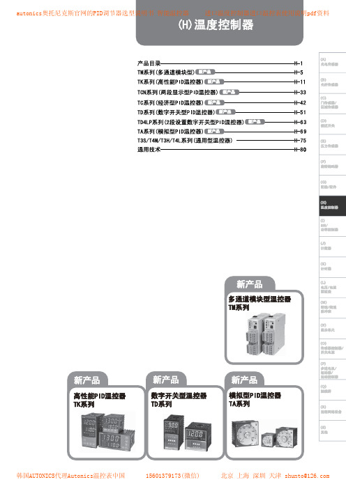
奥托尼克斯pid调节器使用说明书
韩国AUTONICS代理Autonics温控表中国
15601379173(微信)
北京 上海 深圳 天津 shunto@
autonics奥托尼克斯官网的PID调节器选型说明书 智能温控器 进口温度控制器进口温控表使用说明pdf资料
韩国AUTONICS代理Autonics温控表中国
15601379173(微信)
北京 上海 深圳 天津 shunto@
autonics奥托尼克斯官网的PID调节器选型说明书 智能温控器 进口温度控制器进口温控表使用说明pdf资料
韩国AUTONICS代理Autonics温控表中国
1560137917to@
autonics奥托尼克斯官网的PID调节器选型说明书 智能温控器 进口温度控制器进口温控表使用说明pdf资料
autonics奥托尼克斯官网的PID调节器选型说明书 智能温控器 进口温度控制器进口温控表使用说明pdf资料
韩国AUTONICS代理Autonics温控表中国
15601379173(微信)
北京 上海 深圳 天津 shunto@
autonics奥托尼克斯官网的PID调节器选型说明书 智能温控器 进口温度控制器进口温控表使用说明pdf资料
北京 上海 深圳 天津 shunto@
autonics奥托尼克斯官网的PID调节器选型说明书 智能温控器 进口温度控制器进口温控表使用说明pdf资料
韩国AUTONICS代理Autonics温控表中国
15601379173(微信)
北京 上海 深圳 天津 shunto@
autonics奥托尼克斯官网的PID调节器选型说明书 智能温控器 进口温度控制器进口温控表使用说明pdf资料
北京 上海 深圳 天津 shunto@
Autonics奥托尼克斯控制开关教材
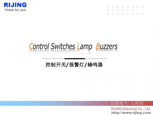
开关接触件
RIJING
Think for you
开关接触件
◎如何拆分触点模块 使用独立的拆分工具,如一字螺丝刀。
◎触点模块是允许多级连接使用,仅触点模块 (SA-□M)是可以多级连接使用的。
2级连接
3级连接
RIJING
Think for you
产品构成--非调光按钮
常开
常闭
操作面板
安装面板
开关接触件
注:接线方法参照指示灯接线
RIJING
Think for you
产品构成--调光按钮
LED灯
常开
常闭
操作面板
安装面板
开关接触件
注:接线方法参照指示灯接线
RIJING
Think for you
蜂鸣器-电磁蜂鸣器
① 移除蜂鸣器底部护盖。
电磁蜂鸣器(非嵌入式)
持续型声音: 哔------, 间隔型声音: 哔-, 哔取出跳线, 声音类型更改为间隔型。
② 使用一字螺丝刀取下跳线。
RIJING
Think for you
蜂鸣器--压电蜂鸣器
12-24VDC
持续型声音 压电蜂鸣器(非嵌入式)
12-24VDC
间隔型声音
RIJING
Think for you
上海总公司
上海市恒丰路610号不夜城都市工业园1号楼6楼 电话:(021)51098191 传真:(021)51017258 E-mail:rijing@ 广州市广州大道中鸿景大厦3B 邮编:510600 电话:(020)61136551 传真:(020)87397793
邮编200070
广州分公司
常州分公司 重庆分公司
常州市常州新区府琛花园1号楼813室 邮编213002 电话:(0519)82090111 传真:(0519)86623939 重庆市长江二路77号万有康年国际公寓B3-1305 电话:(023)68007202 邮编:400042Fra bibliotek接触件
Daikin 拆分式冷却系统产品数据手册说明书

Product DataSplit System Cooling4TTR6018J1000A Array 4TTR6024J1000B4TTR6030J1000A4TTR6036J1000A4TTR6042J1000A4TTR6048J1000A4TTR6049J1000A4TTR6060J1000B4TTR6061C1000BN o t e:“Graphics in this document are for representationonly.Actual model may differ in appearance.”April202022-1916-1J-E NProduct Specifications(a)Certified in accordance with the Unitary Air-conditioner equipment certification program which is based on AHRI standard210/240.(b)Calculated in accordance with N.E.C.Only use HACR circuit breakers or fuses.(c)Standard line lengths—60’,Standard lift—60’Suction and Liquid line.For Greater lengths and lifts refer to refrigerantpiping software Pub#32–3312–0*(*denotes latest revision).(d)25,30,35and50foot linesets available.For a complete listing of lineset options available from equipment or supply stores,refer to the Trane Residential and Light Commercial Product Handbook.P r o d u c t S p e c i f i c a t i o n s(a)210/240.(b)Calculated in accordance with N.E.C.Only use HACR circuit breakers or fuses.(c)Standard line lengths—60’,Standard lift—60’Suction and Liquid line.For Greater lengths and lifts refer to refrigerantpiping software Pub#32–3312–0*(*denotes latest revision).(d)25,30,35and50foot linesets available.For a complete listing of lineset options available from equipment or supply stores,refer to the Trane Residential and Light Commercial Product Handbook.P r o d u c t S p e c i f i c a t i o n s(a)Certified in accordance with the Unitary Air-conditioner equipment certification program which is based on AHRI standard210/240.(b)Calculated in accordance with N.E.C.Only use HACR circuit breakers or fuses.(c)Standard line lengths—60’,Standard lift—60’Suction and Liquid line.For Greater lengths and lifts refer to refrigerantpiping software Pub#32–3312–0*(*denotes latest revision).(d)25,30,35and50foot linesets available.For a complete listing of lineset options available from equipment or supply stores,refer to the Trane Residential and Light Commercial Product Handbook.Note:Rated in accordance with AHRI Standard270–2008Accessory Description and UsageA n t i-S h o r t C y c l e T i m e r—Solid state timing device that prevents compressor recycling untilfive(5)minutes have elapsed after satisfying call or power e in area withquestionable power delivery,commercial applications,long lineset,etc.E v a p o r a t i o n D e f r o s t C o n t r o l—SPST Temperature actuated switch that cycles the condenseroff as indoor coil reaches freeze-up ed for low ambient cooling to30°F with TXV.R u b b e r I s o l a t o r s—Five(5)large rubber donuts to isolate condensing unit from transmittingenergy into mounting frame or e on any application where sound transmission needs tobe minimized.H a r d S t a r t K i t—Start capacitor and relay to assist compressor motor e in areas withmarginal power supply,on long linesets,low ambient conditions,etc.E x t r e m e C o n d i t i o n M o u n t K i t—Bracket kits to securely mount condensing unit to a frame orpad without removing any e in areas with high winds,or on commercial roof tops,etc.A H R I S t a n d a r d C a p a c i t y R a t i n g C o n d i t i o n sAHRI Standard210/240Rating Conditions1.Cooling80°F DB,67°F WB air entering indoor coil,95°F DB air entering outdoor coil.2.High Temperature Heating47°F DB,43°F WB air entering outdoor coil,70°F DB air enteringindoor coil.3.Low Temperature Heating17°F DB air entering indoor coil.4.Rated indoor airflow for heating is the same as for cooling.A H R I S t a n d a r d270R a t i n g C o n d i t i o n s—(Noise rating numbers are determiend with the unit incooling operations.)Standard Noise Rating number is at95°F outdoor air.Model NomenclatureOutdoor Units3 = 134 = 145 = 15Schematic DiagramsFigure1.018—048ModelsD157362P08Figure2.049&061ModelsPRINTED FROM D158442P 02 S c h e m a t i c D i a g r a m sFigure 3.060ModelsS c h e m a t i c D i a g r a m sFigure 4.060ModelsS c h e m a t i c D i a g r a m sOutline DrawingMechanical Specification OptionsG e n e r a lThe outdoor condensing units are factory charged with the system charge required for theoutdoor condensing unit,ten(10)feet of tested connecting line,and the smallest rated indoorevaporative coil match.This unit is designed to operate at outdoor ambient temperatures as highas115°F.Cooling capacities are matched with a wide selection of air handlers and furnace coilsthat are AHRI certified.The unit is certified to UL1995.Exterior is designed for outdoorapplication.C a s i n gUnit casing is constructed of heavy gauge,galvanized steel and painted with a weather-resistantpowder paint finish.The corner panels are prepainted.All panels are subjected to our1,000hoursalt spray test.R e f r i g e r a n t C o n t r o l sRefrigeration system controls include condenser fan,compressor contactor and low and highpressure switches.A factory supplied,field installed liquid line drier is standard.C o m p r e s s o rThe compressor features internal over temperature and pressure protection.Other featuresinclude:Centrifugal oil pump and low vibration and noise.C o n d e n s e r C o i lThe outdoor coil provides low airflow resistance and efficient heat transfer.The coil is protectedon all four sides by louvered panels.L o w A m b i e n t C o o l i n gAs manufactured,this system has a cooling capacity to55°F.The addition of an evaporatordefrost control permits operation to40°F.The addition of an evaporator defrost control with TXVpermits low ambient cooling to30°F.The addition of the BAYLOAM107A low ambient kit permits ambient cooling to20°F.T h e r m o s t a t s—Cooling only and heat/cooling(manual and automatic change over).Sub-base tomatch thermostat and locking thermostat cover.N o t e sN o t e sN o t e sTrane-by Trane Technologies(NYSE:TT),a global innovator-creates comfortable,energy efficient indoor environments for commercial and residential applications.For more information,please visit or .The AHRI Certified mark indicates Trane U.S.Inc.participation in the AHRI Certification program.For verification of individual certified products,go to ahridirectory. org.Trane has a policy of continuous data improvement and it reserves the right to change design and specifications without notice.We are committed to using environmentally conscious print practices.22-1916-1J-EN28Apr2020。
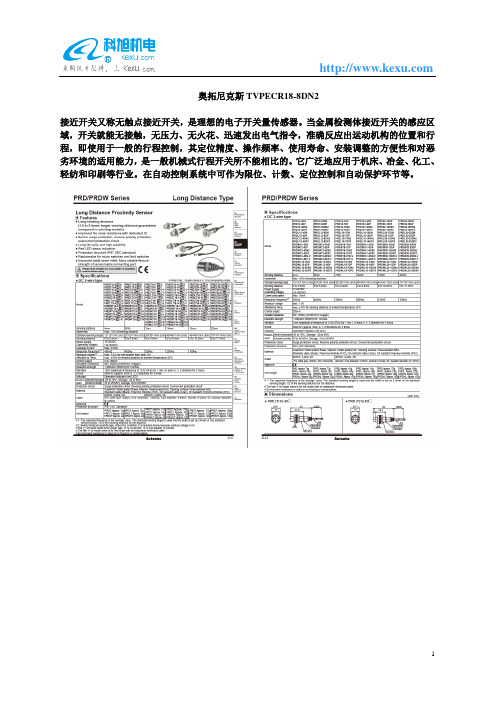
奥拓尼克斯TVPECR18-8DN2
奥拓尼克斯TVPECR18-8DN2
接近开关又称无触点接近开关,是理想的电子开关量传感器。
当金属检测体接近开关的感应区域,开关就能无接触,无压力、无火花、迅速发出电气指令,准确反应出运动机构的位置和行程,即使用于一般的行程控制,其定位精度、操作频率、使用寿命、安装调整的方便性和对恶劣环境的适用能力,是一般机械式行程开关所不能相比的。
它广泛地应用于机床、冶金、化工、轻纺和印刷等行业。
在自动控制系统中可作为限位、计数、定位控制和自动保护环节等。
PSL212-POT-PSAP4电动执行器PSL312 PSL208 PSL210 PS204
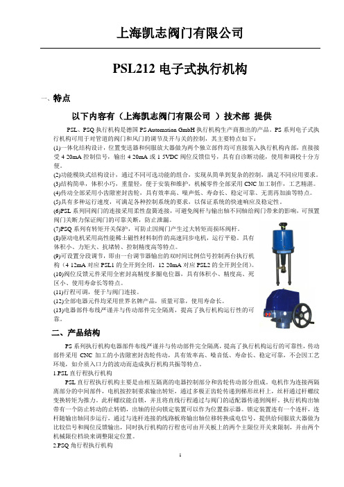
PSL212电子式执行机构一、特点以下内容有(上海凯志阀门有限公司)技术部提供PSL、PSQ执行机构是德国PS Automation GmbH执行机构生产商推出的产品。
PS系列电子式执行机构可用于对管道的阀门和风门的调节及开与关的控制,其主要特点如下:(1)一体化结构设计,位置变送器和伺服放大器做为两个独立部件均可直接装入执行机构内部,直接接受4-20mA控制信号,输出4-20mA或1-5VDC阀位反馈信号,具有自诊断功能,使用和调校十分方便。
(2)功能模块式结构设计,通过不同可选功能的组合,实现从简单到复杂的控制,满足不同应用要求。
(3)结构简单,体积小巧,重量轻,便于安装和维护,机械零件全部采用CNC加工制作,工艺精湛。
(4)传动全部采用小齿隙密封齿轮,具有效率高、噪声低、寿命长、稳定可靠、无需再加油等特点。
(5)具有多种运行速度,可满足各种控制系统的要求,以保证系统的快速响应及稳定性。
(6)PSL系列同阀门的连接采用柔性盘簧连接,可避免阀杆与输出轴不同轴给阀门带来的影响,可预置阀门关断力保证阀门的可靠关断,防止泄漏。
(7)PSQ系列有转矩开关保护,可防止因阀门产生过大转矩而损坏阀杆。
(8)驱动电机采用高性能稀土磁性材料制作的高速同步电机,运行平稳。
具有体积小、力矩大、抗堵转、控制精度高等特点。
(9)可设置分段调节,即由一台调节器输出的双时间比例信号控制两台执行机构(4-12mA对应PSL1的全开到全闭,12-20mA对应PSL2的全开到全闭)。
(10)阀位反馈元件采用全密封高精度多圈电位器,具有体积小、精度高、死区小、使用寿命长等特点。
(11)行程可调,便于与阀门连接。
(12)全部电器元件均采用世界名牌产品,质量可靠,使用寿命长。
(13)电器部件布线严谨并与传动部件完全隔离,提高了执行机构运行性的可靠。
二、产品结构PS系列执行机构电器部件布线严谨并与传动部件完全隔离,提高了执行机构运行的可靠性,传动部件采用CNC加工的小齿隙密封齿轮传动,具有效率高、噪音低、寿命长、稳定可靠,不会因工艺环境,如介质入口力的波动而造成执行机构共振等特点。
施耐德电气TeSys Giga系列控制设备与保护设备产品目录说明书

中国版TeSysTeSys 控制设备 – Giga 接触器TeSys 保护设备 2021 产品目录TeSys 控制设备 – Giga 接触器.............................简介............................................................................说明............................................................................产品参考....................................................................设计人员技术数据...................................................TeSys 保护设备 – Giga 电子过载继电器............简介............................................................................说明............................................................................产品参考....................................................................设计人员技术数据...................................................TeSys Giga 系列 – 设备选型.................................适用于各种应用的Giga 接触器..............................目录2610122127282930313550TeSys 控制设备 – Giga 接触器 TeSys 保护设备 – Giga 热过载继电器智能起动 智能运行TeSys™电动机控制设备首款BAR TeSys D首款三合一TeSys DGiga 接触器Giga 热过载继电器产品参考 - 编码原则Giga 接触器Giga 接触器Giga 接触器 - 简介Giga 接触器 - 简介Giga接触器的独特设计可以满足要求严苛的大功率应用的普遍要求:• 符合多种标准以满足全球需求 • 在严酷环境中的长使用寿命Giga 接触器 - 简介Giga 接触器 - 简介Giga 接触器 - 说明Giga 接触器 - 说明先进的接触器控制• 电子控制模块提供 48V-500V 的宽电压交/直流线圈控制电压,因此可以完美适配现有和新的应用场景。
奥拓尼克斯PSN30-15DN2
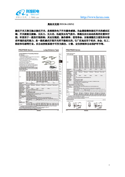
奥拓尼克斯PSN30-15DN2
接近开关又称无触点接近开关,是理想的电子开关量传感器。
当金属检测体接近开关的感应区域,开关就能无接触,无压力、无火花、迅速发出电气指令,准确反应出运动机构的位置和行程,即使用于一般的行程控制,其定位精度、操作频率、使用寿命、安装调整的方便性和对恶劣环境的适用能力,是一般机械式行程开关所不能相比的。
它广泛地应用于机床、冶金、化工、轻纺和印刷等行业。
在自动控制系统中可作为限位、计数、定位控制和自动保护环节等。
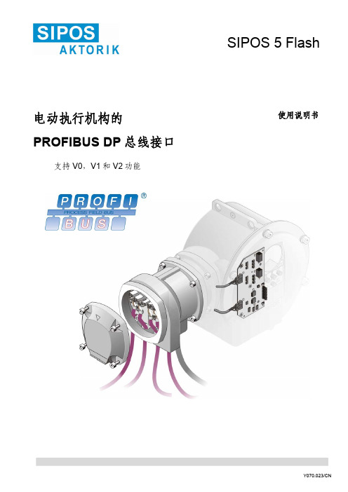
SIPOS电动执行机构Profibus说明书
4
2.3
PROFIBUS-DP: 识别号
4
2.4 设备数据 (GSD)
4
3
带 PROFIBUS 总线接口的 SIPOS 5 Flash 电动执行机构的使用 5
3.1 禁止就地控制单元
5
3.2 显示的故障信息
5
3.3
显示 PROFIBUS 总线的状态
6
4
技术参数
7
4.1
带 PROFIBUS DP 总线接口的 SIPOS 5 Flash 电动执行机构
no transmission … kBits /s Wait Prm Wait Cfg Data Exchange Failsafe GC Clear
POWER_ON S_WAITING S_PRIMARY C_CONFIGURE BACKUP BTP_PARTNER_ACK BTP_SWITCHOVER BTP_PRM_CMD BTP_DX PRIMARY PTB_PARTNER_ACK PTB_SWITCHOVER NIL
识别号24设备数据gsd带profibus总线接口的siposflash电动执行机构的使用31禁止就地控制单元32显示的故障信息33显示profibus总线的状态41带profibusdp总线接口的siposflash电动执行机构42profibusdp总线接口的通信参数1043电气连接铜缆或光纤11设置dp从站的地址13设置通讯和设备参数1461dp状态1462dp从站的参数设置1563配置dp1664用户数据数据交换ppo类型16641输入执行机构17642输出执行机构1865auma过程映像用户数据数据交换19651输入执行机构19652输出执行机构2066监控方式2167扩展的dpv1功能22671im功能识别和维护功能2468冗余24681报文和总线地址24682启动行为25683pzd部分过程数据和auma过程映像25684pkw部分ppo1和ppo2的参数识别值2569sipos冗余25691msac1类主站与从站的非循环数据通信25692切换标准25610扩展的dpv2功能266101pno冗余2661011设置从站地址2761012prmcmd2761013扩展的诊断redstatusprmcmdack286102时间同步和时间标签2961021激活时间标签2961022timear参数块3061023clockvalue报文3061024过程报警3161025读数据记录3261026时间标签和冗余32参考文献59附录profibusdp总线的参数列表3444数据记录profibusdpv14558安全须知警告标识表示如果操作不当将会损害人身或财产的安全
温控器TK4S-14S设置技术通告

技术通告产品线 CEMS-2000 技术通告编号 CEMS16100901编制人 王盟 编制日期 2016年10月9日发布对象 运维服务部、营销服务部、方案设计中心全体人员适用范围 CEMS-2000所有产品系列审核人 陈志伟 审核日期技术通告内容:温控器设置技术通告温控器设置1)操作面板:温控器型号为韩国奥托尼克斯TK4S-14S✧按键说明:PV:测量温度SV:目标温度OUT1:加热输出AL1:亮,表示温度报警产生(AL2示启用,不会出现)MODE:菜单键“长按3S进入Par1/2/3/4/5后可以进行参数设置《:是在设置数字时选择位数︽与︾:选择设置项或者设置数字的大小2)温控器设置✧传感器类型设置:测量主界面 → 按MODE键 3s以上到PAr1 → 按两次“︽”到PAr3 → 按MODE到In-t(传感器类型)→ 按“︾”键数次到dpt.H(PT100类型)→ 长按MODE键3S以上返回测量主界面✧开启报警设置:测量主界面 → 按MODE键 3s以上到PAr1 → 按三次“︽”到Par4 → 按MODE到AL-1(报警模式1)→ 按“︽”或“︾”调到]du[(产生报警)→ 按MODE保存设置 → 长按MODE键3S以上返回测量主界面✧报警偏差上下限设置:测量主界面 → 按MODE键 3s以上到PAr1 → 按三次MODE到AL1.L(偏差下限)→设为10按MODE 保存设置→按MODE到AL1.H(偏差上限)→ 设为10按MODE保存设置→ 长按MODE键3S以上返回测量主界面✧目标温度设置:测量主界面 → 直接按“《“、“︽”和“︾”设定相应温度 → 按MODE保存设置✧自整定设置方法:1)在运行模式下,按“MODE”键约3 秒以上,当出现“Par 1”界面时松开。
2)按一下“MODE”键,进入到“PAr 2”界面3)按一下“MODE”键,进入到“At”界面4)按一下“︽”键,将 “oFF” 设置为“on”5)按“MODE”键确认设置,按“MODE”键3秒以上返回主界面。
成都奥托尼克斯温控器说明书

成都奥托尼克斯温控器说明书1.接通智能温控器的电源,显示屏上显示的是当前的温度。
因为传感器未接触其他器件,而是直接暴露在空气中,所以这就是现在的气温:31摄氏度,还不算太热。
2.显示屏右下方是“启动温度”设置按钮,按升温键一下,温度提高1摄氏度;也可以按住不放手,温度连续升高。
这里我设置为65摄氏度,也就是传感器温度低于或等于65度时,输出插座自动通电,所连接的设备启动。
设备可以是电动机、电加热器等等。
3.显示屏左下方是“停止温度”设置按钮。
我设置为80度,即传感器温度高于或等于80度时,输出插座自动断电,受控设备停止工作。
4.再看温度传感器,它的作用是感知被监测对象的温度,并转变为电信号,通过导线传回温控器。
可以拿一个铁质物品试一下,传感器有较强磁性,能吸附其上。
5.现在,把传感器吸附在被监测的设备上。
当然,这个设备得有铁质部分;否则,就得想办法固定了。
6.把受控设备的插头插在温控器输出插座上。
注意:最好在温控器本身未加电的状态下进行。
至此,设置工作完成,温控器加电,该系统就开始工作了。
注意事项:必须明确温控器的输出功率,受控设备的电功率必须小于这个指标。
1.设定温度:按SET键可设定或查看温度设定点。
按一下SET键数码管字符开始闪动,表示仪表进入设定状态,按△键设定值增加,按▽键设定值减小,长按△键或▽键数据会快速变动,再一次按SET 键仪表回到正常工作状态温度设定完毕。
2.回差控制(XMT201-C):按SET键3秒仪表进入内层参数设定状态。
第一个出现并闪动的参数为C00即回差值,回差控制参数要慎重调整,仪表控制加热输出值到设定值,当温度下跌到设定值减回差值时又开始加热,在回差范围内输出(继电器)是不动作的,这样可减少继电器动作次数以利延长继电器寿命。
例:若设定值是80.0℃,回差为0.5,仪表控制加热到80.0℃时继电器释放,温度下跌到80.0℃-0.5℃=79.5℃时继电器又吸合。
回差值越大继电器动作次数越少,回差值过大会降低控制精度。
奥托尼克斯电容式接近开关

奥托尼克斯电容式接近开关奥托尼克斯电容式接近开关:助力智能交通和工业自动化进一步升级奥托尼克斯电容式接近开关是一种新型传感器,它的出现极大地推动了智能交通和工业自动化行业的发展。
那么,究竟这款产品有着哪些亮点呢?下面我们就来一一了解。
产品原理奥托尼克斯电容式接近开关,其工作原理是通过检测电容变化来检测靠近的物体。
在电容线圈和物体靠近时,电容值会随之变化,从而产生电容变化信号,即透过电路输出信号。
根据电容式接近开关不同的用途,采用的线圈和检测距离也有着不同。
产品亮点1. 长寿命:电容式接近开关使用的材料天然无污染,因此长久使用不会造成磨损和损坏。
2. 反应速度快:电容式接近开关的响应时间特别短,可以高效地监测物体的移动,并及时反馈。
3. 检测范围广:电容式接近开关检测的距离远,具有超强的侦测距离,便于远距离检测,准确度可靠。
4. 精度高:电容式接近开关可以检测物体的材质、性质、形状和大小,实现非接触式精准检测。
应用领域奥托尼克斯电容式接近开关的应用领域广泛,包括智能交通、机械制造、电力设备、自动化控制、医疗器械和航空航天等多个领域。
1. 智能交通:奥托尼克斯电容式接近开关可以感知车道内人车物,自动识别车型,并能够自动避让,大大提升交通安全性。
2. 机械制造:奥托尼克斯电容式接近开关可以感知物体的位置、大小和类型,实现自动化控制,提高生产效率和产量。
3. 电力设备:奥托尼克斯电容式接近开关可以检测高压缺陷,优化电力设备运行状态,提高电气设备的工作效率和安全性。
4. 自动化控制:奥托尼克斯电容式接近开关可以实现自动控制、调整、监测等多种功能,帮助企业降低成本、提高生产效率。
5. 医疗器械:奥托尼克斯电容式接近开关可以感知医疗器械和人体组织的距离和位置,实现非侵入性探测,提高手术和治疗的精度和安全性。
总结奥托尼克斯电容式接近开关,以其精准、快速、检测距离远、寿命长等优秀特性成为智能交通和工业自动化领域的重要装备,为推动行业升级换代和进一步提升高科技、高精度、高效率提供了强有力的支持。
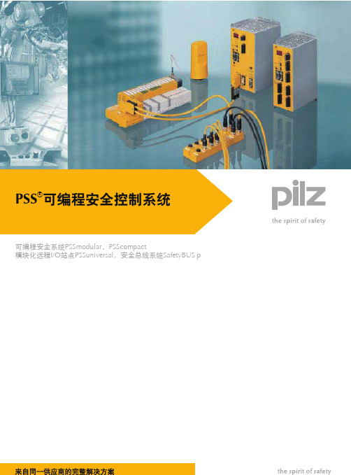
PSS可编程安全控制系统
PSSu E S RS232 PSSu E S RS485
2个 模拟量输入 4个 模拟量输入 2个 模拟量输入 2个 模拟量输出 4个 模拟量输出 2个 模拟量输出 2个 模拟量输入 2个 模拟量输入
绝对值编码器 增量式编码器 增量式编码器
◆◆ ◆◆
◆ ◆
笼式弹簧夹持端子 1)
合适的底座模块 订货号 PSSu BP 1/8 S 2) .........312 600 PSSu BP-C 1/8 S 3) ....312 610 PSSu BP 1/12 S ...........312 618 PSSu BP-C 1/12 S .....312 620 PSSu BP-C1 1/12 S ...312 622 PSSu BP 2/16 S ...........312 628 PSSu BP-C 2/16 S .....312 630 PSSu BP 1/8 C 2) ........312 601 PSSu BP-C 1/8 C 3) ....312 611 PSSu BP 1/12 C ...........312 619 PSSu BP-C 1/12 C .......312 621 PSSu BP-C1 1/12 C ...312 623 PSSu BP 2/16 C ...........312 629 PSSu BP-C 2/16 C .......312 631
故障安全功能 标准功能
PSSu E F PS 数字量输入和输出
PSSu E F PS PSSu E F PS1 PSSu E F PS-P PSSu E F BSW
型号
供电电压 供电电压,缓存 供电电压,外围
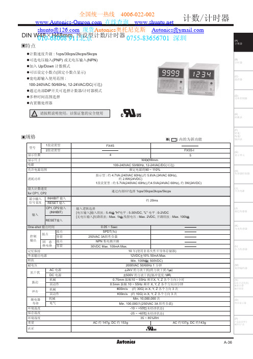
韩国Autonics计数器FX4S说明书PDF资料奥托尼克斯样本
WLPH
I[;V
/2GAll0 /tE.
/tH+A I;d/t/QSQ0
E2;^/tU*TfEX;=;/|X*TfV *Tf UO 87j >u hu I[V KG 289Y <5;j \l;L *Tf >u hu I[V KG 289Y <5;j \l;L 7Y 7Y
E.:/t
I[V KG 289Y <5;j \l;L
`
`
`
`
UHVH
`
`
`
`
UHVH
`
`
`
`
UHVH
`
`
`
`
UHVH
7 8 9 :
2 2 2 2
7 8 9 :
2 2 2 2
7 8 9 :
2 2 2 2
7 8 9 :
2 2 2 2
WLPH
WLPH
WLPH
WLPH
I[;V
I[;V
I[;V
I[;V
UXQ lnde
xvZY+Z>7?7@0V gv0tT2:w2Y +
EI[<V4L
0755-83656701 深圳
PG
FS8 FS9 /Qnre80 /Qnre90
PG
=
>
?
@ 87
7Y
=
\;/|
>
?
@ 87
/Qnre80 A SQS /t /Qnre90 A QSQ /t FS9/LQKLELW0A 4y|f~l| BE]x? By|f~l|v;e=y|5
/LQKLELW0 289Y /<7lD0
/K0 *Tf;3f
德国THYRACONT真空计、变送器、控制器、真空开关介绍

德国THYRACONT真空计、变送器、控制器、真空开关介绍德国THYRACONT由英格·海因茨·普洛钦格于1970年创立,50多年来一直在开发和生产智能、创新的真空计量。
从一开始,创新精神就是我们取得卓yue 技术成就的动力,这些成就一再在真空测量和控制技术中创造新的动力。
Thyracont的独te之处在于它融合了传统和创新。
“THYRACONT”的名称由冷冻干燥机的功率控制器中的“晶闸管”和“控制器”组成。
50多年的真空测量专业知识是我们不断优化和完善产品的基础。
Thyracont开发的许多创新,例如微型Pirani螺旋丝或在大测量范围内使用组合传感器,已成为真空测量的标准。
产品组合包括真空计、真空传感器、真空变送器、真空表、真空开关、控制器以及配件和真空组件。
根据客户要求,可以提供各种组合的测量原理,如:压电、皮拉尼、电容、冷阴极和热阴极…1) VD8真空计:准确的便携式的数字的测量范围1600至5e-4mbar|1200至5e-4Torr带有集成数据记录器的紧凑型数字真空计可记录您的工艺值。
先进的电子设备保证了精确和可重复的测量结果。
参考型号:VD81 Piezo|VD83 Pirani|VD84 Pirani external|VD85Piezo/Pirani功能:数据记录器,最多可提供2000个测量值使用电源装置或电池进行操作用于数据传输的USB接口泄漏率计算连续运行或自动关闭◆通用仪表VD8真空计可用作便携式仪器或永jiu安装在真空设施中。
真空计可以通过电池或插入式电源进行操作。
◆舒适的测量记录所有VD8紧凑型真空计都具有集成的数据记录器,并在整个测量过程中独立于PC保存压力值。
◆精确的结果紧凑型真空计的显示屏显示精确的绝对压力。
温度补偿传感器和先进的电子设备保证了精确和可重复的测量结果。
◆最大灵活性VD84型仪表在螺旋电缆上有一个外部Pirani传感器。
它非常适合将传感器安装在难以触及的位置。
DualGuard-S ESF30 KV 装置安装与操作指南说明书

Mounting and Operating Instructions compact Fire-resistant cabinet type DualGuard-S ESF30 KVTarget group: qualified electricians according to DIN VDE 0105 Part 1ContentContent1 Important notes . . . . . . . . . . . . . . . . . . . . . . . .31.1 General information (3)1.2 Explanation of symbols. . . . . . . . . . . . . . . . . . .31.3 I nformation on the assembly and installationinstructions (4)1.4 Other applicable documents (4)1.5 L iability, warranty and declaration of surrender 41.7Spare parts (4)1.8 Disposal (4)2 Safety . . . . . . . . . . . . . . . . . . . . . . . . . . . . . . . . .42.2 Contents of the assembly and installation inst-ructions (5)2.3 M odifications and conversions to the unit (5)2.4 Responsibility of the operator (5)2.5 Requirements for the personnel (5)2.6 Occupational safety (5)3 T echnical data . . . . . . . . . . . . . . . . . . . . . . . . . .54 Layout . . . . . . . . . . . . . . . . . . . . . . . . . . . . . . . .64.1 DualGuard-S ESF30 SOU5 and SOU4 (6)4.1.1 C omponents DualGuard-S ESF30 SOU5 andSOU4 (6)4.1.2 D rawings DualGuard-S ESF30 SOU5 andSOU4 (6)4.2 DualGuard-S ESF30 SOU3 (6)4.2.1 Components DualGuard-S ESF30 SOU3 (6)4.2.2 Drawings DualGuard-S ESF30 SOU3 (6)4.3 DualGuard-S ESF30 SOU2 (7)4.3.1 Components DualGuard-S ESF30 SOU2 (7)4.3.2 Drawings DualGuard-S ESF30 SOU2 (7)4.4 DualGuard-S ESF30 SOU1 (7)4.4.1 Components DualGuard-S ESF30 SOU1 (7)4.4.2 Drawings DualGuard-S ESF30 SOU1 (7)5 T ransport . . . . . . . . . . . . . . . . . . . . . . . . . . . . . .85.1 T he most important aspects of transport inbrief (8)6 A ssembly and installationDualGuard-S ESF30 SOU5, SOU4, SOU3,SOU2, SOU1 . . . . . . . . . . . . . . . . . . . . .96.1 Wall mounting (9)6.2 Inserting the cables (9)Notes 10Attention! Danger of tipping over2Mounting and Operating Instructions DualGuard-S ESF30 KV 40071860406 (A) March 2022 1 Important notes1 Important notes1.1 General informationInstallation work may only be carried out by qualified elec-tricians (cf. DIN VDE 0105 part 1, the accident prevention regulation Accident Prevention Regulation BGV A3 of the main of the Employer‘s Liability Insurance Associations or analogous regulations and directives of the country in which the system is installed and operated). Other persons may carry out the activities described in this manual only if they have been properly and professionally instructed, and have received proper instruction,• t heir tasks and activities have been precisely defined and understood.• t he activities are carried out under the supervision and control of• c ompetent personnel.Observe:• t he requirements of the usability certificates• t he regulations of the MLAR, MBO, technical building regulations• t he extended documentation obligations resulting from the • a mendment of the MBO.• a ll instructions for maintenance contracts!• t he instructions in the safety data sheets for building materials!• K eep the swivel area of the door free and always keep the door closed!• Only use the system when it is in proper condition!• F or installation, operation and maintenance, the respective accident prevention and DI N/VDE regulations must be observed.• T he area of application of the products e.g.according to the proof of usability must be checked by the customer.• I mpairment of the stability of the system when doors are open if the system has not yet been screwed to the building structure.IMPORTANT NOTE:• The operator is required by the applicant of a general buil-ding authority approval/general type approval• general building approval must inform the operator in writing that the fire protection system• t hat the fire protection system only meets the require-ments of fire resistance only when closed. This has been done herewith.• I mproper installation may impair the protective function.• S crew connections to the building may only be made with approved, s uitable screws/dowels.• T he suitability of the screws/dowels must be checked depending on the building.• T he enclosures must not be glued, painted or otherwise coated.• T hey must not be damaged (holes, screws) on the corpus. (holes, screws). T he locking systems must not be changed or exchanged.• W hen working with these assembly and installation instructions the following instructions, marked with an attention symbol and a symbol and a password, the follo-wing instructions to be observed.1.2 Explanation of symbolsImportant safety instructions in these operating instructionsare marked with symbols.Gives important tips and advice on the procedure or handlingof the described devices or system parts.mage to plants or plant damage to installations or parts ofinstallations as well as environmental can be.to persons or persons or serious damage to installations orparts of installations and serious environmental damage. threatening injuries to persons or serious damage, whichindirectly pose a danger to persons or the environment.tions are only intended to illustrate the described circum-stances.Wherever• work is carried out with dimensional accuracy or• p recise drawings adapted to the special features on site, the drawings are required, the drawings that have been dra-wings that have been specially prepared for the installation.sional and have been instructed in the local and operational conditions!I n the case of extensions, conversions, repairs or work that is work that is not described in these instructions are to be carried out by specially trained specialist and service personnel (of the manufacturer CEAG or sales and service companies authorised by CEAG)!3Mounting and Operating Instructions DualGuard-S ESF30 KV 40071860406 (A) March 2022 4Mounting and Operating Instructions DualGuard-S ESF30 KV 40071860406 (A) March 2022 2 Safety1.3 I nformation on the assembly and installa-tion instructionsThese installation and operating instructions are intended for practical use and must be made available to the user/installer at the place of use of the fire protection system. They do not release the installer from the obligation to comply with all details and specifications of the usability and to use the systems immediately at the check the delivery. Keep these installation and and operating instructions inside the fire protection system. Safe and proper functioning of the system is only guaranteed if the following instructions and safety information are followed. A warranty with regard to the IP class is only possible with proper installation. Please keep these assembly and installation instructions carefully, as they are an integral part of the supplied electrical distribution board. Safe and approved function is only ensured if these instructions are observed.1.4 Other applicable documentsIn addition to the assembly and installation instructions the installation and operating instructions of the central battery systems DualGuard-S must be observed.1.5 L iability, warranty and declaration of surrender• I n order to ensure optimal functioning of our products the installation instructions must be observed.• C EAG‘s warranty extends to the products supplied. • M odifications or alterations to the design may only be carried out after consultation with CEAG, otherwise the approval/warranty will expire.• T he warranty for installation services is to be assumed by the installer. • W arranty and liability claims for personal injury and are excluded if they are due to one or more of the following causes:• F ire protection enclosures are not used as intended. • I mproper installation, commissioning, operation and maintenance.• N on-observance of the instructions regarding transport, storage, operation and assembly.• U nauthorised structural modifications to the fire protection enclosures.• I nadequate monitoring of the safety devices to be installed. improper repairs.• c atastrophes caused by third parties and force majeure.Property rightsTo safeguard innovation and design utility models have been deposited.GeneralWe expressly reserve the right to make technical changes that serve to improve the enclosures or that are caused by legal changes - even without separate notification.All information and notes in these assembly and installation instructions have been compiled taking into account the ap-plicable regulations, the state of the art and our many years of knowledge and experience. The assembly and installation instructions must be kept in the immediate vicinity of the unitand accessible at all times to all persons working on or with the unit. These assembly and installation instructions must be read carefully before starting any work on or with the unit!1.6 Copyright protectionThe assembly and installation instructions are to be treated confidentially. T hey are intended exclusively for persons wor-king on and with the unit. All information regarding content, texts, drawings, pictures and other illustrations are protectedin the sense of the copyright law.Spare partsOnly use original spare parts from the manufacturer. Incorrect or faulty spare parts can lead to damage, malfunctions or total failure of the unit. If unapproved spare parts are used, the 1.8 DisposalUnless a take-back or disposal agreement has been disas-sembled components for recycling after proper disassembly.2 SafetyAt the time of its development and manufacture, the app-liance in accordance with the applicable, recognised rules of technology and is considered safe to operate. However, hazards may arise from this unit if it is used by untrained personnel, improperly or not or if it is not used for the inten-ded purpose. The special regulations in this manual must be observed. Observe the standards and regulations of the VDE, the DIN.Make sure• t hat the requirements of the fire protection authorities are observed and are complied with,• t hat the requirements of the building supervisory authori-ties are observed are complied with,• t hat the conditions of the technical building regulations for your for your federal state are complied with, take into account the Model Cable Systems Directive (MLAR).• t hat the installation of the enclosure increases the fire re-sistance duration and the stability of the fire wall to which the enclosure has been reduced.• t hat the enclosure does not show any damage, e.g. cracks or displacements in the insulation,• t hat the enclosure is always closed during operation,• t hat the swivel area of the door is always free,2.1 Intended use5Mounting and Operating Instructions DualGuard-S ESF30 KV 40071860406 (A) March 2022 2 Safety2.4 Responsibility of the operatorThese operating instructions must be kept in the immediate vicinity of the unit and must be accessible at all times to persons working on and with the unit. The unit may only be operated if it is in a technically perfect and operationally safe condition. T he unit must be checked for integrity before each start-up. The information in the operating instructions must be followed completely and without restriction!2.5 Requirements for the personnelThese operating instructions must be read and understood in the immediate vicinity of the appliance and only authorised and trained personnel may work with the appliance. The personnel must have received instruction on any hazards that may occur. Qualified personnel are those who, on the basis of their technical training, knowledge and experience as well as knowledge of the relevant regulations, are able to assess the work assigned to them and recognise possible dangers.2.6 Occupational safetyBy following the safety information and instructions in this manual can prevent personal injury and damage during work with and on the unit can be avoided.The electrical distribution board with function maintenance type DualGuard-S ESF30 is used for the battery-supported monitoring and power supply for emergency lighting. It may only be:- used as intended and- be used in a safe and proper condition.used in a safe condition. When handling the products and for the correct the cable entry, please follow these operating instructions exactly. Any other use is considered improper. CEAG Notlichtsysteme is not liable for any damage or con-sequential damage resulting from this.2.2 Contents of the assembly and installation instructionsEvery person who is assigned to carry out work on or with the unit must have read and understood the operating instruc-tions before starting work on the unit. This also applies if the person concerned has already worked with such a device or similar devices or has been trained by the manufacturer.2.3 M odifications and conversions to the unitT o avoid hazards and to ensure optimum performance, no mo-difications, additions or conversions may be made to the unit that have not been expressly approved by the manufacturer..TypeDualGuard-S ESF30 SOU5DualGuard-S ESF30 SOU4 IO DualGuard-S ESF30 SOU3DualGuard-S ESF30 SOU2DualGuard-S ESF30 SOU1Certificates Empty enclosure DIBT DIBT DIBT DIBT DIBT Fire exposure from outside (min)3030303030Housing data HousingFire protection panels Fire protection panels Fire protection panels Fire protection panels Fire protection panels Degree of protection IP54IP54IP54IP54IP54Protection class IIIIIIIIIIDimensions (H x W x D in mm)1228 x 478 x 2951228 x 478 x 295928 x 478 x 295778 x 478 x 295628 x 478 x 295Weight (kg) Raw cabinet 103103806960Closing Swivelling lever with Double pinSwivelling lever with Double pinSwivelling lever with Double pin Swivelling lever with Double pin Swivelling lever with Double pin Electrical data Rated voltage 230 V 50/60 Hz 230 V 50/60 Hz 230 V 50/60 Hz 230 V 50/60 Hz 230 V 50/60 Hz Number of module slots 54321Max. Cable cross-section End circuits (mm²)44444Max. Individual conductor cross-section (mm²)1010101010Max. Total conductor cross-section (mm²)14324811398833 Technical data4 Layout4.1 DualGuard-S ESF30 SOU5 and SOU4 4.1.1 C omponents DualGuard-S ESF30 SOU5and SOU44.2 DualGuard-S ESF30 SOU34.2.1 Components DualGuard-S ESF30 SOU3EnclosureS witch-over modulesSOU CG-S 2 x 4 AEnclosureS witch-over modulesSOU CG-S 2 x 4 A 4 Layout1112226Mounting and Operating Instructions DualGuard-S ESF30 KV 40071860406 (A) March 2022 4 Layout4.3 DualGuard-S ESF30 SOU24.3.1 Components DualGuard-S ESF30 SOU2EnclosureS witch-over modulesSOU CG-S 2 x 4 A4.4 DualGuard-S ESF30 SOU14.4.1 Components DualGuard-S ESF30 SOU1EnclosureS witch-over modulesSOU CG-S 2 x 4 A 11227 Mounting and Operating Instructions DualGuard-S ESF30 KV 40071860406 (A) March 2022 5 Transport5 Transport5.1 The most important aspects of transport in brief• D elivery of the fire protection system on a transport pallet • T he systems must be inspected immediately upon delivery and any visible defects must be noted immediately on the consignment note.• D efects must be reported in writing (no later than 5 working days after delivery).• T he transfer of risk is upon delivery. Defects which have arisen due to onward transport of the systems, are exclu-ded from subsequent fulfilment.• Transport of the fire protection system to the place of use with a suitable forklift truck on a transport pallet, protective corners and strapping• I mproper transport (hard knocks, transport without air suspension, repeated reloading, one-sided loading when loading on one side during installation, etc.) can have an effect on the fire protection function (damage to the fire protection panels or their connections).• I f the system has to be moved, this must be done only be carried out evenly and over the entire surface.• The system must be closed off.8Mounting and Operating Instructions DualGuard-S ESF30 KV 40071860406 (A) March 2022 9Mounting and Operating Instructions DualGuard-S ESF30 KV 40071860406 (A) March 2022 6 Assembly and installation DualGuard-S ESF30 SOU5, SOU4, SOU3, SOU2, SOU14 x fasteners 1 x double bit key 1 x instruction manual 1 x maintenance checklist (2. L ift the system with a suitable lifting device e.g. scissor lift truck to the specified installation height.3. A lign the manifold vertically on the wall and secure it with the the pre-drilled holes in the back panel/fixing lug. Observe the diagonal dimension. Do not drill into the rear wall! Caution: Danger of breakage!4. Component thickness6 A ssembly and installationDualGuard-S ESF30 SOU5, SOU4, SOU3, SOU2, SOU16.1 Wall mounting General notesUneven wall surfaces that are not touched by the fire pro-tection system, are to be (Crystal-CEL), provided that these have a gap of more than 5 mm or if smoke is likely to escape in the event of a fire. Walls must be level and plumb.Normal tolerances of the walls/plaster must be compensated for in such a way that smoke- and fire-proof installation is possible.For the installation on the wall, only the materials described in the the …General Building Inspectorate Approval“ may be used. The wall on which the distributor is to be mounted must have sufficient load-bearing capacity. The fire resi-stance of the supporting walls should be at least as high as that of the distributor. With the help of the enclosed screw anchors, DualGuard-S ESF30 can be easily screwed on via the fastening holes in the housing - in both cracked and non-cracked concrete. A distance of at least one metre from neighbouring installations such as gas or water is required. In In the vicinity of doors, a distance corresponding to the door must be maintained.1. Check the accessories for completeness:6.2 Inserting the cablesThe cable entry as a system component of the electrical enclosure consists of:a) a metal cover,b) the intumescent andendothermic areas The metal cover with different dimensi-ons, depending on the type of distribution board, is provided with holes. T he cables are to be inserted through these holes. To do this, the insulation layer visible through the holes must be removed with a drill (with a drill bit approx. 2 mm smaller than the diameter of the cable). T his makes it easier to insert the cable. When piercing the red or blue intumescent, make sure that the the red or blue intumescent must be guided straight. To achieve strain relief for the cables, a cable rail is to be mounted on the equipment support inside the cabinet and directly in front of the cable inlet outside the cabinet andattach the cables to it.The exact drilling depth depends on the dowel length and is to be be determined as follows: Required drilling depth = anchor length- component thickness + 10 mm- Minimum anchoring depth of the enclosed dowels: 70 mm;- Drill diameter: 10 mm5. S uck out the drill dust, drive in the dowel - through-fixing (screw head flush) and tighten the screw screw with a suitable wrench/screwdriver - do not overtighten! tighten - do not overtighten! Do not countersink the screw head into the into the material.6. P ush the plastic caps onto the fastening anchors and press them firmly. and press firmly. (optional)7. S pray the plastic caps of the fastening anchors with fire protection putty to around the plastic caps of the fasteninganchors to ensure the protection class. (optional)NotesNotes10Mounting and Operating Instructions DualGuard-S ESF30 KV 40071860406 (A) March 2022 Notes Notes11 Mounting and Operating Instructions DualGuard-S ESF30 KV 40071860406 (A) March 2022 Eaton is a registered trademark.All other trademarks are the property of their respective owners.The aim of Eaton is to provide a reliable, efficient and safe power supply where it is needed most. Eaton's experts have comprehensive in-depth specialist knowledge in the area of energy management in the most diverse of sectors and therefore they are able to provide customer-specific, integrat-ed solutions to meet the most challenging demands of its customers.It is our highest priority always to find the right solution for every application. Our stakeholders therefore expect more than just innovative products. Companies turn to Eaton because they know that individual support and the success of our customers is always our top priority. For more information visit .Eaton Industries Manufacturing GmbH Electrical Sector EMEA Route de la Longeraie 7 1110 Morges, Switzerland Eaton.euCEAG Notlichtsysteme GmbH Senator-Schwartz-Ring 2659494 Soest, Germany Tel.: +49 (0) 2921 69-870Fax: +49 (0) 2921 69-617E-mail:**************Web: © 2022 Eaton All rights reserved.Printed in Germany Order no. 40071860406 (A)Publication no. MN451102EN March 2022。
- 1、下载文档前请自行甄别文档内容的完整性,平台不提供额外的编辑、内容补充、找答案等附加服务。
- 2、"仅部分预览"的文档,不可在线预览部分如存在完整性等问题,可反馈申请退款(可完整预览的文档不适用该条件!)。
- 3、如文档侵犯您的权益,请联系客服反馈,我们会尽快为您处理(人工客服工作时间:9:00-18:30)。
奥拓尼克斯PS30-15DP
接近开关又称无触点接近开关,是理想的电子开关量传感器。
当金属检测体接近开关的感应区域,开关就能无接触,无压力、无火花、迅速发出电气指令,准确反应出运动机构的位置和行程,即使用于一般的行程控制,其定位精度、操作频率、使用寿命、安装调整的方便性和对恶劣环境的适用能力,是一般机械式行程开关所不能相比的。
它广泛地应用于机床、冶金、化工、轻纺和印刷等行业。
在自动控制系统中可作为限位、计数、定位控制和自动保护环节等。
