M210064BLN中文资料
尼龙软管规格书
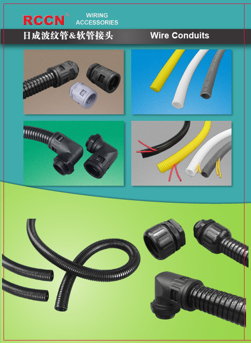
材 质:PA
Material:PA
产品认证: 欧洲CE, 欧洲环保ROHS
Certificate: CE, ROHS
特 性:安装容易,适合于两端线头已固定 Features:easy to stall,suitabel to wire
使用方法:将电线电缆放入管内即可 下表型号数据参考 BG系列
fixed in both terminals How to use:input the cables or wires Datas,please refer to BG series
静态 弯曲 半径 Stat.r
13 20 35 40 45 55 65 90 100 13 20 45 50 50
单位/Unit:mm
动态 弯曲 半径 Dyn.r
包装 Packing
M
35 100M 45 100M 55 100M 65 100M 75 100M 100 50M 120 50M 150 50M 190 25M 25 100M 45 100M 75 100M 85 50M 110 50M
温 度:-40℃-125℃,短时达到150℃ Work Temperature:-40℃ to125℃,
产品认证: 美国UL,欧洲CE, 欧洲环保 150℃ in short time
ROHS,REACH.
Color:black
防火等级:94V0。
Certificates: CE,ROHS,REACH.
阻
日成系列软管接头使用即可.
tested according to RCCN factory
BG-25NB
BG-25NG
- 25.5 31.5 50 110 50M
燃
不锈钢管规格表(全)
不锈钢管规格表I.圆管编号0611ZY0804 0611ZY0904 0611ZY0905 0611ZY0906 0611ZY0907 0611ZY0908 0611ZY0909 0611ZY0910 0611ZY10210 0611ZY10212 0611ZY10215 0611ZY10220 0611ZY10225 0611ZY11412 0611ZY11415 0611ZY11420 0611ZY11425 0611ZY1204 0611ZY1205 0611ZY1206 0611ZY1207 0611ZY1208 0611ZY1209名称8x0.4圆管9.5X0.4圆管9.5x0.5圆管9.5X0.6圆管9.5X0.7圆管9.5X0.8圆管9.5X0.9圆管9.5x1.0圆管102x1.0圆管102x1.2圆管102x1.5圆管102x2.0圆管102x2.5圆管114x1.2圆管114x1.5圆管114x2.0圆管114x2.5圆管12.7x0.4圆管12.7x0.5圆管12.7x0.6圆管12.7x0.7圆管12.7x0.8圆管0611ZY121012.7x1.0圆管0611ZY12707 0611ZY12710 0611ZY12715 0611ZY12720 0611ZY13315 0611ZY13320 0611ZY13330 0611ZY1404 0611ZY1405 0611ZY1409 0611ZY14115 0611ZY14120 0611ZY14125 0611ZY1430 0611ZY15915 0611ZY15920 0611ZY15925 0611ZY1604 0611ZY1605 0611ZY1606 0611ZY1607 0611ZY1608 0611ZY1609 0611ZY1610 0611ZY1612 0611ZY1615 0611ZY1682012.7x0.7圆管12.7x1.0圆管12.7x1.5圆管12.7x2.0圆管133x1.5圆管133x2.0圆管133x3.0圆管14x0.4圆管14x0.5圆管14x0.9圆管141x1.5圆管141x2.0圆管141x2.5圆管141x3.0圆管159x1.5圆管159x2.0圆管159x2.5圆管16x0.4圆管16x0.5圆管16x0.6圆管16x0.7圆管16x0.8圆管16x0.9圆管16x1.0圆管16x1.2圆管0611ZY16825168x2.5圆管0611ZY1904 0611ZY1905 0611ZY1906 0611ZY1907 0611ZY1908 0611ZY1909 0611ZY1910 0611ZY1912 0611ZY1915 0611ZY21920 0611ZY21930 0611ZY2204 0611ZY2205 0611ZY2206 0611ZY2207 0611ZY2208 0611ZY2209 0611ZY2210 0611ZY2212 0611ZY2215 0611ZY2220 0611ZY2504 0611ZY2505 0611ZY2506 0611ZY2507 0611ZY2508 0611ZY2509 0611ZY251019x0.4圆管19x0.5圆管19x0.6圆管19x0.7圆管19x0.8圆管19x0.9圆管19x1.0圆管19x1.2圆管19x1.5圆管219x2.0圆管219x3.0圆管22x0.4圆管22x0.5圆管22x0.6圆管22x0.7圆管22x0.8圆管22x0.9圆管22x1.0圆管22x1.2圆管22x1.5圆管22x2.0圆管25x0.4圆管25x0.5圆管25x0.6圆管25x0.7圆管25x0.8圆管25x0.9圆管0611ZY2512 25x1.2正标圆管0611ZY2514 25x1.4正标圆管0611ZY2515 25x1.5正标圆管0611ZY2520 25x2.0正标圆管0611ZY3205 32x0.5正标圆管0611ZY3206 32x0.6正标圆管0611ZY3207 32x0.7正标圆管0611ZY3208 32x0.8正标圆管0611ZY3209 32x0.9正标圆管0611ZY3210 32x1.0正标圆管0611ZY3212 32x1.2正标圆管0611ZY3215 32x1.5正标圆管0611ZY3220 32x2.0正标圆管0611ZY3806 38x0.6正标圆管0611ZY3807 38x0.7正标圆管0611ZY3808 38x0.8正标圆管0611ZY3809 38x0.9正标圆管0611ZY3810 38x1.0正标圆管0611ZY3812 38x1.2正标圆管0611ZY3815 38x1.5正标圆管0611ZY3820 38x2.0正标圆管0611ZY5106 51x0.6正标圆管0611ZY5107 51x0.7正标圆管0611ZY5108 51x0.8正标圆管0611ZY5109 51x0.9正标圆管0611ZY5110 51x1.0正标圆管0611ZY5112 51x1.2正标圆管0611ZY5115 51x1.5正标圆管0611ZY5120 51x2.0正标圆管0611ZY6307 63x0.7正标圆管0611ZY6308 63x0.8正标圆管0611ZY6309 63x0.9正标圆管0611ZY6310 63x1.0正标圆管0611ZY6312 63x1.2正标圆管0611ZY6315 63x1.5正标圆管0611ZY6340 63x4.0正标圆管0611ZY7608 76x0.8正标圆管0611ZY7609 76x0.9正标圆管0611ZY7610 76x1.0正标圆管0611ZY7612 76x1.2正标圆管0611ZY7615 76x1.5正标圆管0611ZY7620 76x2.0正标圆管0611ZY8909 89x0.9正标圆管0611ZY8910 89x1.0正标圆管0611ZY8912 89x1.2正标圆管0611ZY8915 89x1.5正标圆管0611ZY8920 89x2.0正标圆管0611ZY8930 89x3.0正标圆管。
Belden 14 AWG 氧化铜导线说明书

1
14 104x34
Total Number of Conductors:
1
Insulation Insulation Material:
Insulation Material
Wall Thickness (mm)
HDPE - High Density Polyethylene 0.8128
Overall Insulation Overall Cable
EU Directive 2011/65/EU (ROHS II):
Yes
EU CE Mark:
No
EU Directive 2000/53/EC (ELV):
Yes
EU Directive 2002/95/EC (RoHS):
Yes
EU RoHS Compliance Date (mm/dd/yyyy):
07/01/2004
EU Directive 2002/96/EC (WEEE):
Yes
EU Directive 2003/11/EC (BFR):
Yes
CA Prop 65 (CJ for Wire & Cable):
Yes
MII Order #39 (China RoHS):
Yes
Plenum/Non-Plenum
Page 2 of 2
11-05-2015
Plenum (Y/N):
No
Electrical Characteristics (Overall)
Nom. Conductor DC Resistance: DCR @ 20°C (Ohm/km) 8.26812
Suggested Working Voltage:
电线电缆规格型号说明及含义完整版

电线电缆规格型号说明及含义Document serial number【NL89WT-NY98YT-NC8CB-NNUUT-NUT108】电线电缆规格型号说明及含义作者:本站?来源:发布时间:2008-6-28 13:15:00[] [] 电线电缆规格型号说明注:B (B )——第一个字母表示布线,第二个字母表示玻璃丝编 制;V (V )——第一个字母表示聚乙烯(塑料)绝缘,第二个字母 表示聚乙烯护套; L (L 铝, 无L 则表示铜; F (F )——复 合型; R ——软线; S ——双绞;X ——绝缘橡胶 电缆型号含义 电力电缆(省略不表示)外护层代号含义第一个数字 第二个数字 代号 0细圆钢丝 粗圆钢丝代号常见电缆型号说明及用途型号名称用途型号 名称用途BX (BLX ) BXF (BLXF ) BXR铜(铝)芯橡皮绝缘线 铜(铝)芯氯丁橡皮绝缘线 铜芯橡皮绝缘软线适用交流500V 及以下或直流1000V 及以下的电气设备及照明装置之用 BV (BLV ) BVV (BLVV ) BVVB (BLVVB ) BVR BV-105铜(铝)芯聚氯乙烯绝缘线铜(铝)芯聚氯乙烯绝缘氯乙烯护套圆形电线铜(铝)芯聚氯乙烯绝缘氯乙烯护套平形电线铜(铝)芯聚氯乙烯绝缘软线 铜芯耐热105°C 聚氯乙烯绝缘软线适用于各种交流、直流电器装置,电工仪表、仪器,电讯设备,动力及照明线路固定敷设之用RV RVB RVS RV-105 RXS RX铜芯聚氯乙烯绝缘软线 铜芯聚氯乙烯绝缘平行软线 铜芯聚氯乙烯绝缘绞型软线铜芯耐热105°C 聚氯乙烯绝缘连接软电线 铜芯橡皮绝缘棉纱编织绞型软电线 铜芯橡皮绝缘棉纱编织圆型软电线适用于各种交流、直流电器、电工仪表、家用电器、小型电动工具、动力及照明装置的连接 BBX BBLX 铜芯橡皮绝缘玻璃丝编织电线 铝芯橡皮绝缘玻璃丝编织电线适用电压分别有500V 及250V 两种,用于室内外明装固定敷设或穿管敷设铜芯NA-YJV,NB-YJV,交联聚乙烯绝缘聚氯乙烯护套A(B)类耐火电力电缆可敷设在对耐火有要求的室内、隧道及管道中。
整流桥型号大全

上海好明电子整流桥型号上海好明电子专业生产整流桥,二极管,三极管,LED,PTC,整流模块等产品整流桥分类为:1、LED迷你整流桥;2、整流桥圆桥;3、整流桥扁桥;4、整流桥方桥。
◆LED迷你整流桥:◇MBS封装:MB1S、MB2S、MB4S、MB6S、MB8S、MB10S◇MBM封装:MB1M、MB2M、MB4M、MB6M、MB8M、MB10M◇DB封装:DB101、DB102、DB103、DB104、DB105、DB106、DB107◇DBS封装:DB101S、DB102S、DB103S、DB104S、DB105S、DB106S、DB107S◆整流桥圆桥:◇WOW封装:W005M、W01M、W02M、W04M、W06M、W08M、W10M◇WOW封装:2W005M、2W01M、2W02M、2W04M、2W06M、2W08M、2W10M◆整流桥扁桥:◇KBP封装:KBP2005、KBP201、KBP202、KBP204、KBP206、KBP208、KBP210◇KBP封装:RS201、RS202、RS203、RS204、RS205、RS206、RS207◇GBP封装:GBP2005、GBP201、GBP202、GBP204、GBP206、GBP208、GBP210◇KBP封装:RS301、RS302、RS303、RS304、RS305、RS306、RS307◇KBL封装:KBL4005、KBL401、KBL402、KBL404、KBL406、KBL408、KBL410◇GBU封装:GBU4005、GBU401、GBU402、GBU404、GBU406、GBU408、GBU410◇KBJ封装:KBJ4005、KBJ401、KBJ402、KBJ404、KBJ406、KBJ408、KBJ410◇GBL封装:GBL4005、GBL401、GBL402、GBL404、GBL406、GBL408、GBL410◇KBU封装:、KBU601、KBU602、KBU604、KBU606、KBU608、KBU610◇GBU封装:GBU6005、GBU601、GBU602、GBU604、GBU606、GBU608、GBU610◇KBJ封装:KBJ6005、KBJ601、KBJ602、KBJ604、KBJ606、KBJ608、KBJ610◇KBU封装:KBU8005、KBU801、KBU802、KBU804、KBU806、KBU808、KBU810◇GBU封装:GBU8005、GBU801、GBU802、GBU804、GBU806、GBU808、GBU810◇KBJ封装:KBJ8005、KBJ801、KBJ802、KBJ804、KBJ806、KBJ808、KBJ810◇KBU封装:KBU10005、KBU1001、KBU1002、KBU1004、KBU1006、KBU1008、KBU1010◇GBU封装:GBU10005、GBU1001、GBU1002、GBU1004、GBU1006、GBU1008、GBU1010◇KBJ封装:KBJ10005、KBJ1001、KBJ1002、KBJ1004、KBJ1006、KBJ1008、KBJ1010◇GBJ封装:GBJ15005、GBJ1501、GBJ1502、GBJ1504、GBJ1506、GBJ1508、GBJ1510◇GBJ封装:GBJ25005、、GBJ2502、GBJ2504、GBJ2506、GBJ2508、GBJ2510◆整流桥方桥:◇KBPC3封装:KBPC3005、KBPC301、KBPC302、KBPC304、KBPC306、KBPC308、KBPC310◇KBPC6封装:KBPC6005、KBPC601、KBPC602、KBPC604、KBPC606、KBPC608、KBPC610◇KBPC8封装:KBPC8005、KBPC801、KBPC802、KBPC804、KBPC806、KBPC808、KBPC810◇KBPC8封装:KBPC10005、KBPC1001、KBPC1002、KBPC1004、KBPC1006、KBPC1008、KBPC1010、◇MB-35封装:KBPC15005、KBPC1501、KBPC1504、KBPC1506、KBPC1508、KBPC1510◇MB-35W封装:KBPC15005W、KBPC1501W、KBPC1504W、KBPC1506W、KBPC1508W、KBPC1510W◇GBPC35封装:GBPC15005、GBPC1501、GBPC1502、GBPC1504、GBPC1506、GBPC1508、GBPC1510◇GBPC35W封装:GBPC15005W、GBPC1501W、GBPC1502W、GBPC1504W、GBPC1506W、GBPC1508W、GBPC1510W ◇MB-35封装:KBPC25005、KBPC2501、KBPC2502、KBPC2504、KBPC2506、KBPC2508、KBPC2510◇MB-35W封装:KBPC25005W、KBPC2501W、KBPC2502W、KBPC2504W、KBPC2506W、KBPC2508W、KBPC2510W ◇GBPC35封装:GBPC25005、GBPC2501、GBPC2502、GBPC2504、GBPC2506、GBPC2508、GBPC2510◇GBPC35W封装:GBPC25005W、GBPC2501W、GBPC2502W、GBPC2504W、GBPC2506W、GBPC2508W、GBPC2510W ◇MB-35封装:KBPC35005、KBPC3501、KBPC3502、KBPC3504、KBPC3506、KBPC3508、KBPC3510◇MB-35W封装:KBPC35005W、KBPC3501W、KBPC3502W、KBPC3504W、KBPC3506W、KBPC3508W、KBPC3510W ◇GBPC35封装:GBPC35005、GBPC3510、GBPC3502、GBPC3504、GBPC3506、GBPC3508、GBPC3510◇GBPC35W封装:GBPC35005W、GBPC3510W、GBPC3502W、GBPC3504W、GBPC3506W、GBPC3508W、GBPC3510W ◇MB-35封装:KBPC40005、KBPC4001、KBPC4002、KBPC4004、KBPC4006、KBPC4008、KBPC4010◇GBPC35封装:GBPC40005、GBPC4001、GBPC4002、GBPC4004、GBPC4006、GBPC4008、GBPC4010◇MB-35封装:KBPC50005、KBPC5001、KBPC5002、KBPC5004、KBPC5006、KBPC5008、KBPC5010◇MB-35W封装:KBPC50005W、KBPC5001W、KBPC5002W、KBPC5004W、KBPC5006W、KBPC5008W、KBPC5010W ◇GBPC35封装:GBPC50005、GBPC5001、GBPC5002、GBPC5004、GBPC5006、GBPC5008、GBPC5010◇GBPC35W封装:GBPC50005W、GBPC5001W、GBPC5002W、GBPC5004W、GBPC5006W、GBPC5008W、GBPC5010W。
速控器标准型型 elbow 型(金属体)说明书

Doc. no. AS*-OMW0046-ASPEED CONTROLLER STANDARD TYPEELBOW TYPE (METAL BODY)AS1400-M3AS12*0~AS42*01.Safety Instructions 2 ~3 2.Specific Product Precautions 4 ~6 3.Application 7 4.Specifications 7 5.Troubleshooting 7 6.Construction 8-1-Speed Controller Standard TypeElbow Type (Metal Body) / AS SeriesSafety InstructionsThese safety instructions are intended to prevent hazardous situations and/or equipment damage.These instructions indicate the level of potential haz ard with the labels of “Caution,” “Warning” or “Danger.”They are all important notes for safety and must be followed in addition to International Standards (ISO/IEC)*1) , and other safety regulations.*1) ISO 4414: Pneumatic fluid power -- General rules relating to systems.ISO 4413: Hydraulic fluid power -- General rules relating to systems.IEC 60204-1: Safety of machinery -- Electrical equipment of machines .(Part 1: General requirements)ISO 10218: Manipulating industrial robots -Safety.etc.Caution Caution indicates a hazard with a low level of risk which, if not avoided, could result in minor or moderate injury.Warning Warning indicates a hazard with a medium level of risk which, if not avoided, couldresult in death or serious injury.Danger Danger indicates a hazard with a high level of risk which, if not avoided, will resultin death or serious injury.Warning1. The compatibility of the product is the responsibility of the person who designs the equipment or decides its specifications.Since the product specified here is used under various operating conditions, its compatibility with specific equipment must be decided by the person who designs the equipment or decides its specifications based on necessary analysis and test results.The expected performance and safety assurance of the equipment will be the responsibility of the person who has determined its compatibility with the product.This person should also continuously review all specifications of the product referring to its latest catalog information, with a view to giving due consideration to any possibility of equipment failure when configuring the equipment.2. Only personnel with appropriate training should operate machinery and equipment.The product specified here may become unsafe if handled incorrectly.The assembly, operation and maintenance of machines or equipment including our products must be performed by an operator who is appropriately trained and experienced.3. Do not service or attempt to remove product and machinery/equipment until safety is confirmed.1.The inspection and maintenance of machinery/equipment should only be performed after measures toprevent falling or runaway of the driven objects have been confirmed.2.When the product is to be removed, confirm that the safety measures as mentioned above are implementedand the power from any appropriate source is cut, and read and understand the specific product precautions of all relevant products carefully.3. Before machinery/equipment is restarted, take measures to prevent unexpected operation and malfunction.4. Contact SMC beforehand and take special consideration of safety measures if the product is to be used in any of the following conditions.1. Conditions and environments outside of the given specifications, or use outdoors or in a place exposed todirect sunlight.2. Installation on equipment in conjunction with atomic energy, railways, air navigation, space, shipping,vehicles, military, medical treatment, combustion and recreation, or equipment in contact with food and beverages, emergency stop circuits, clutch and brake circuits in press applications, safety equipment or other applications unsuitable for the standard specifications described in the product catalog.3. An application which could have negative effects on people, property, or animals requiring special safetyanalysis.e in an interlock circuit, which requires the provision of double interlock for possible failure by using amechanical protective function, and periodical checks to confirm proper operation.Speed Controller Standard TypeElbow Type (Metal Body) / AS SeriesSafety InstructionsCaution1. The product is provided for use in manufacturing industries.The product herein described is basically provided for peaceful use in manufacturing industries.If considering using the product in other industries, consult SMC beforehand and exchange specifications or a contract if necessary.If anything is unclear, contact your nearest sales branch.Limited warranty and Disclaimer/Compliance RequirementsThe product used is subject to the following “Limited warranty and Disclaimer” and “Compliance Requirements”.Read and accept them before using the product.Limited warranty and Disclaimer1. The warranty period of the product is 1 year in service or 1.5 years after the product is delivered, whichever is first.Also, the product may have specified durability, running distance or replacement parts. Please consult your nearest sales branch.2. For any failure or damage reported within the warranty period which is clearly our responsibility,a replacement product or necessary parts will be provided.This limited warranty applies only to our product independently, and not to any other damage incurred due to the failure of the product.3. Prior to using SMC products, please read and understand the warranty terms and disclaimersnoted in the specified catalog for the particular products.Compliance Requirements1. The use of SMC products with production equipment for the manufacture of weapons of massdestruction(WMD) or any other weapon is strictly prohibited.2. The exports of SMC products or technology from one country to another are governed by therelevant security laws and regulation of the countries involved in the transaction. Prior to the shipment of a SMC product to another country, assure that all local rules governing that export are known and followed.CautionSMC products are not intended for use as instruments for legal metrology.Measurement instruments that SMC manufactures or sells have not been qualified by type approval tests relevant to the metrology (measurement) laws of each country.Therefore, SMC products cannot be used for business or certification ordained by the metrology (measurement) laws of each country.2. Specific Product PrecautionsWarning(1) Confirm the specifications.Do not operate at pressures, temperatures, etc., beyond the range of specifications, as this can cause damage or malfunction. (Refer to the specifications.)Please contact SMC when using a fluid other than compressed air (including vacuum).We do not guarantee against any damage if the product is used outside of the specifications range.(2)Products mentioned in this catalog are not designed for use as stop valves with zero air leakage.A certain amount of leakage is allowed in the products specifications. Tightening the needle to reduce leakage to zero may result in equipment damage.(3)Do not disassemble the product or make anymodifications, including additional machining.Doing so may cause human injury and/or an accident.(4)The flow rate characteristics for eachproduct are representative values.The flow rate characteristics are characteristics of each individual product. Actual values may differ depending on the piping, circuitry, pressure conditions, etc. Also, depending on product specifications, there may be variations in the zero needle rotations position of the flow rate characteristics.(5)Check if that PTFE can be used in application.PTFE powder (Polytetrafluoroethylene resin) is included in the seal material for piping taper thread of male thread type. Confirm that the use of it will not cause any adverse effect on the system.Please contact SMC if the Safety Data Sheet (SDS) is required.Warning(1) Operation ManualInstall the products and operate it only after reading the operation manual carefully and understanding its contents. Also, keep the manual where it can be referred to as necessary.Warning(2)Ensure sufficient space for maintenance activities.When installing the products, allow access for maintenance.(3)Confirm that the lock nut is tightened.A loose lock nut may cause speed changes in the actuator.(4)Check the degree of rotation of the needlevalve.The Products in this catalog are retainer type so that the needle is not removed completely. Over rotation will cause damage.(5)Do not use tools such as pliers to rotate theknob.This can cause idle rotation of the knob or damage.(6) Confirm the air flow direction.Mounting backward is dangerous, because the speed adjustment needle will not work and the actuator may lurch suddenly.(7) Adjust the needle by opening the needle slowly after having closed it completely.Loose needle valves may cause unexpected sudden actuator lurching.When a needle valve is turned clockwise, it is closed and cylinder speed decreases. When a needle valve is turned counterclockwise, it is open and cylinder speed increases.(8)Do not apply excessive force or shock to the body or fittings with an impact tool. This can cause damage or air leakage.(9)Tighten threads with the proper tightening torque.When installing the products, follow the listed proper torque.(10)For installation/removal, please tighten the hexagonal width across flats of Body B (AS1400-M3: joint) with an appropriate spanner.Do not apply torque at other points as the product may be damaged. For AS22*0~AS42*0, the Body A can be rotated after installation.Design/ SelectionMountingMountingCaution(1) Tightening methodThe proper tightening torques of the fitting are as shown in the table below. As a guide, tighten by hand, then turn it two or three turns with a wrench. Pay attention not to over tighten the product. Check the dimensions of each product for the hexagon width across flats.(2)The proper tightening torques for hexagonlock nuts are shown in the table below. For standard installation, turn 15 to 30゜using a tool after fastening by hand.Pay attention not to over tighten the product. Check the dimensions for each product for the width across flats.Caution(1)Refer to the Fittings & Tubing Precautions for handing One-touch fittings.(2) Preparation before pipingBefore piping is connected, it should be thoroughly blown out with air (flushing) or washed to remove chips, cutting oil and other debris from inside the pipe.(3)Winding of sealant tapeWhen screwing together pipes and fittings, etc., be certain that chips from the pipe threads and sealing material do not get inside the pipe. Also, when the sealant tape is used, leave approx. 1 thread ridges exposed at the end of the threads.Warning(1) Type of fluidsPlease consult with SMC when using the product in applications other than compressed air.(2) When there is a large amount of drainage Compressed air containing a large amount of drainage can cause the malfunction of pneumatic equipment. An air dryer or water separator should be installed upstream from filters.(3) Drain flushingIf condensation in the drain bowl is not emptied on a regular basis, the bowl will overflow and allow the condensation to enter the compressed air lines. This causes the malfunction of pneumatic equipment.If the drain bowl is difficult to check and remove, the installation of a drain bowl with an auto drain option is recommended.For compressed air quality, refer to SMC catalog "Compressed Air Purification System".(4) Use clean airDo not use compressed air that contains chemicals, synthetic oils that include organic solvents, salt, corrosive gases, etc., as it can cause damage or malfunction.Caution(1) Install an air filter.Install an air filter upstream near the valve. Select an air filter with a filtration size of 5μm or smaller.(2)Take measures to ensure air quality, such as by installing an aftercooler, air dryer, or water separator.Compressed air that contains a large amount of drainage can cause the malfunction of pneumatic equipment, such as flow control equipment. Therefore, take appropriate measures to ensure air quality, such as by providing an aftercooler, air dryer, or water separator.(3) Ensure that the fluid and ambient temperatures are within the specified range. If the fluid temperature is 5℃ or less, the moisture in the circuit could freeze, causing damage to the seals or leading to equipment malfunction. Therefore, take appropriate measures to prevent freezing.For compressed air quality, refer to SMC catalog "Compressed Air Purification System".Air SupplyPiping MountingOperating environmentWarning(1) Do not use in an atmosphere containing corrosive gases, chemicals, sea water, water, water steam, or where there is direct contact with any of these.Refer to each construction drawing for information on the materials of flow control equipment.(2) Do not expose the product to direct sunlightfor an extended period of time.(3) Do not use in a place subject to heavy vibration and/or shock.(4) Do not mount the product in locations where it is exposed to radiant heat.MaintenanceWarning(1)Perform maintenance and inspection according to the procedures indicated in the operation manual.If handled improperly, malfunction or damage of machinery and equipment may occur.(2) Maintenance workIf handled improperly, compressed air can be dangerous.Assembly, handling, repair and element replacement of pneumatic systems should be performed by a knowledgeable and experienced person.(3) Drain flushingRemove drainage from air filters regularly. (4) Removal of equipment, andsupply/exhaust of compressed airBefore components are removed, first confirm that measures are in place to prevent workpieces from dropping, run-away equipment, etc.Then, Cut the supply pressure and electric power, and exhaust all compressed air from the system using the residual pressure release function.When machinery is restarted, proceed with caution after confirming that appropriate measures are in place to prevent sudden movement.3. ApplicationThis product is designed to control the speed of a pneumatic actuator.4. Specifications5.Troubleshooting6.ConstructionAS1400-M34-14-1, Sotokanda, Chiyoda-ku, Tokyo 101-0021 JAPANTel: + 81 3 5207 8249 Fax: +81 3 5298 5362URL https://Note: Specifications are subject to change without prior notice and any obligation on the part of the manufacturer. © 2022 SMC Corporation All Rights Reserved。
不锈钢牌号对照表之欧阳文创编

不锈钢牌号对照表
欧阳文创编
欧阳文创编
欧阳文创编
欧阳文创编
世界金属牌号对照表
碳素结构钢
欧阳文创编
欧阳文创编
[返回]优质碳素结构钢
欧阳文创编
欧阳文创编
欧阳文创编
欧阳文创编
欧阳文创编
[返回]碳素工具钢
欧阳文创编
[返回]合金结构钢
欧阳文创编
欧阳文创编
欧阳文创编
欧阳文创编
欧阳文创编
欧阳文创编
[返回]淬透性合金结构钢
欧阳文创编
欧阳文创编
[返回]弹簧钢
欧阳文创编
[返回]滚动轴承钢
[返回]高速工具钢
欧阳文创编
欧阳文创编
[返回]不锈耐酸钢
欧阳文创编
欧阳文创编
欧阳文创编
[返回]耐热钢
欧阳文创编
欧阳文创编
[返回]易切结构钢
欧阳文创编
合金工具钢
欧阳文创编
欧阳文创编
欧阳文创编
欧阳文创编。
常用国标电线电缆的型号和规格之欧阳治创编

常用国标电线电缆的型号和规格(1)类别:H——市内通信电缆 HP——配线电缆 HJ——局用电缆(2)绝缘:Y——实心聚烯烃绝缘 YF——泡沫聚烯烃绝缘 YP——泡沫/实心皮聚烯烃绝缘(3)内护层:A——涂塑铝带粘接屏蔽聚乙烯护套 S——铝,钢双层金属带屏蔽聚乙烯护套 V——聚氯乙烯护套(4)特征:T——石油膏填充 G——高频隔离 C——自承式(5)外护层:23——双层防腐钢带绕包销装聚乙烯外被层 33——单层细钢丝铠装聚乙烯被层 43——单层粗钢丝铠装聚乙烯被层 53——单层钢带皱纹纵包铠装聚乙烯外被层 553——双层钢带皱纹纵包铠装聚乙烯外被层 2) BV 铜芯聚氯乙烯绝缘电线; BLV 铝芯聚氯乙烯绝缘电线; BVV 铜芯聚氯乙烯绝缘聚氯乙烯护套电线; BLVV 铝芯聚氯乙烯绝缘聚氯乙烯护套电线; BVR 铜芯聚氯乙烯绝缘软线; RV 铜芯聚氯乙烯绝缘安装软线; RVB 铜芯聚氯乙烯绝缘平型连接线软线; BVS 铜芯聚氯乙烯绝缘绞型软线; RVV 铜芯聚氯乙烯绝缘聚氯乙烯护套软线; BYR 聚乙烯绝缘软电线; BYVR 聚乙烯绝缘聚氯乙烯护套软线; RY 聚乙烯绝缘软线;RYV 聚乙烯绝缘聚氯乙烯护套软线 3)电缆的型号由八部分组成:一、用途代码-不标为电力电缆,K为控制缆,P为信号缆;二、绝缘代码-Z油浸纸,X橡胶,V聚氯乙稀,YJ交联聚乙烯三、导体材料代码-不标为铜,L为铝;四、内护层代码-Q铅包,L铝包,H橡套,V聚氯乙稀护套五、派生代码-D不滴流,P干绝缘;六、外护层代码七、特殊产品代码-TH湿热带,TA干热带;八、额定电压-单位KV 有关电缆型号的问题 1、SYV:实心聚乙烯绝缘射频同轴电缆 2、SYWV(Y):物理发泡聚乙绝缘有线电视系统电缆,视频(射频)同轴电缆(SYV、SYWV、SYFV)适用于闭路监控及有线电视工程 SYWV(Y)、SYKV 有线电视、宽带网专用电缆结构:(同轴电缆)单根无氧圆铜线物理发泡聚乙烯(绝缘)(锡丝铝)聚氯乙烯(聚乙烯) 3、信号控制电缆(RVV护套线、RVVP屏蔽线)适用于楼宇对讲、防盗报警、消防、自动抄表等工程 RVVP:铜芯聚氯乙烯绝缘屏蔽聚氯乙烯护套软电缆电压300V/300V2-24芯用途:仪器、仪表、对讲、监控、控制安装 4、RG:物理发泡聚乙烯绝缘接入网电缆用于同轴光纤混合网(HFC)中传输数据模拟信号 5、KVVP:聚氯乙烯护套编织屏蔽电缆用途:电器、仪表、配电装置的信号传输、控制、测量 6、RVV(227IEC52/53)聚氯乙烯绝缘软电缆用途:家用电器、小型电动工具、仪表及动力照明 7、AVVR 聚氯乙烯护套安装用软电缆 8、SBVV HYA 数据通信电缆(室内、外)用于电话通信及无线电设备的连接以及电话配线网的分线盒接线用 9、RV、RVP 聚氯乙烯绝缘电缆 10、RVS、RVB 适用于家用电器、小型电动工具、仪器、仪表及动力照明连接用电缆 11、BV、BVR 聚氯乙烯绝缘电缆用途:适用于电器仪表设备及动力照明固定布线用 12、RIB 音箱连接线(发烧线) 13、KVV 聚氯乙烯绝缘控制电缆用途:电器、仪表、配电装置信号传输、控制、测量 14、SFTP 双绞线传输电话、数据及信息网 15、UL2464 电脑连接线16、VGA 显示器线 17、SYV 同轴电缆无线通讯、广播、监控系统工程和有关电子设备中传输射频信号(含综合用同轴电缆) 18、SDFAVP、SDFAVVP、SYFPY 同轴电缆,电梯专用 19、JVPV、JVPVP、JVVP 铜芯聚氯乙烯绝缘及护套铜丝编织电子计算机控制电缆电线电缆命名与型号电线电缆命名与型号命名原则及案例: 电线电缆的完整命名通常较为复杂,所以人们有时用一个简单的名称(通常是一个类别的名称)结合型号规格来代替完整的名称,如“低压电缆”代表0.6/1kV级的所有塑料绝缘类电力电缆。
Jamesbury Series 2” – 4” (DN 50 – 100) 6300, 2” –
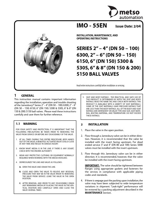
IMO - 55ENIssue Date:2/04INSTALLATION,MAINTENANCE,AND OPERATING INSTRUCTIONSSERIES 2”– 4”(DN 50 – 100)6300,2”– 6”(DN 50 – 150)6150,6”(DN 150) 5300 & 530S,6”& 8”(DN 150 & 200)5150 BALL VALVES1GENERALThis instruction manual contains important information regarding the installation,operation and trouble shooting of the Jamesbury®Series 2”– 4”(DN 50 – 100) 6300,2”– 6”(DN 50 – 150) 6150,6”(DN 150) 5300 & 530S,6”& 8”(DN 150 & 200) 5150 ball valves.Please read these instructions carefully and save them for further reference.2INSTALLATION1.Place the valve in the open position.2.Flow through a Jamesbury valve can be in either direc-tion.However,it is recommended that the valve be installed with the insert facing upstream.For dead ended service 3”and 4”(DN 80 and 100) Series 5000valves must be installed with the insert upstream.3.Flow through this Jamesbury valve can be in eitherdirection.It is recommended,however,that the valve be installed with the insert facing upstream.IMPORTANT:The valve should be tightened between flanges using appropriate gaskets and fasteners for the service,in compliance with applicable piping codes and standards.4.If there is seepage past the packing upon installation,thevalve may have been subjected to wide temperature variations in shipment.“Leak-tight”performance will be restored by a packing adjustment described in the MAINTENANCESection.1.1WARNINGFOR YOUR SAFETY AND PROTECTI ON,T I S I MPORTANT THAT THE FOLLOW NG PRECAUT ONS BE TAKEN PR OR TO REMOV NG THE VALVE FROM SERVICE OR BEFORE ANY DISASSEMBLY OF THE VALVE.1.AT ALL TI MES DURI NG THI S ENTI RE PROCEDURE,KEEP HANDSOUT OF THE VALVE,A REMOTELY ACTUATED VALVE COULD CLOSE AT ANY TIME AND RESULT IN SERIOUS INJURY.2.KNOW WHAT MEDI A I S I N THE LI NE. F THERE I S ANY DOUBT,CHECK WITH THE PROPER AUTHORITY.3.WEAR ANY PROTECTIVE CLOTHING OR EQUIPMENT NORMALLYREQUIRED WHEN WORKING WITH THE MEDIA INVOLVED.4.DEPRESSURIZE THE LINE AND VALVE AS FOLLOWS:A.OPEN THE VALVE AND DRAIN THE LINE.B.CLOSE AND OPEN THE VALVE TO REL EVE ANY RES DUALPRESSURE THAT MAY BE IN THE VALVE PRIOR TO REMOVING THE VALVE FROM SERVI CE.LEAVE THE VALVE I N THE OPEN POSITION.C.AFTER REMOVAL AND PRI OR TO ANY DI SASSEMBLY,DRAI NANY REMAINING MEDIA BY PLACING THE VALVE IN THE VER-T CAL POS T ON AND CAREFULLY OPEN AND CLOSE THE VALVE SEVERAL TIMES.5.SEAT AND BODY RATI NGS - THE PRACTI CAL AND SAFE USE OFTHI S PRODUCT I S DETERMI NED BY BOTH THE SEAT AND BODY RATINGS.READ THE NAME TAG AND CHECK BOTH RATINGS.THIS PRODUCT I S AVAI LABLE WI TH A VARI ETY OF SEAT MATERI ALS.SOME OF THE SEAT MATERIALS HAVE PRESSURE RATINGS THAT ARE LESS THAN THE BODY RATINGS.ALL OF THE BODY AND SEAT RATINGS ARE DEPENDENT ON VALVE TYPE AND SIZE,SEAT MATE-RIAL,BOLTING MATERIAL,AND TEMPERATURE.DO NOT EXCEED THESE RATINGS.Read entire instructions carefully before installation or servicing3MAINTENANCE1.General Maintenance requires periodic observation toensure that the valve is functioning well.Routine maintenance consists of tightening the packing nut (15) periodically to compensate for stem seal wear.This may be done as follows:A.Manual Valves - Loosen the handle screw (18)and tighten the packing nut (15) until snug,then tighten an additional 1/4 turn.Retighten the handle screw.B.Actuated Valves - When the valve is connected to an actuator by a no-play (clamped) type coupling,loosen the coupling before tightening the packing nut.2.Overhaul Maintenance consists of replacing seats andseals.A standard service kit consisting of these parts may be obtained through your Metso Automation Distributor (See Table 1).Refer to the DISASSEMBLY AN D ASSEMBLY Sections below for details on installing the service kits.3.1DisassemblyNOTE:I f complete disassembly becomes necessary,replacement of all seats and seals is recommended.Refer to the Service Kit Chart.1.Read the WARNING Section before performing anywork on the valve.2.Open and close the valve and leave in the closed position.3.4”(DN 100) 6300,6”(DN 150) 6150,6”(DN 150) 530S,6”(DN 150) 5300 and 8”(DN 200) 5150 when equipped with a manual tee handle,remove the cap screw (18)and washer (19) holding the pipe handle to the stem.Then remove the pipe handle (17) and the tee handle adapter (16).4.For 2”(DN 50) 6300,2”(DN 50) 6153,3”(DN 80) 6300,4”(DN 100) 6150 and 6”(DN 150) 5150 valves when equipped with handle remove the cap screw (18) and handle (17).TABLE 1Service Kits4”(DN 100)2”(DN 50)4”(DN 100)6”(DN 150)6300VALVE 61503”(DN 80)615061503”(DN 80)6”(DN 150)SIZE2”(DN 50)61506”(DN 150) 8”(DN 200)6300530S &6300515051506”(DN 150)5300PTFE RKN79TT RKN80TT RKN81TT RKN10TT RKN82TT RKN12TTSEATS FILLED RKN79MT RKN80MT RKN81MT RKN10MT RKN82MT RKN12MT PTFE SEATS PFA RKN79BT RKN80BTRKN81BTRKN10BT RKN82BTRKN12BTSEATS UHMW RKN79UU RKN80UU RKN81UU RKN10UU RKN82UU RKN12UU SEATS PFA RKN79BP RKN80BP RKN81BPRKN10BP RKN82BPRKN12BPSEATS SEALSStandard service kits include seats,stem seals and a 316 stainless steel/PTFE spiral wound body seal.The body seal is suitable for valves with carbon or 316SS trim.25.Remove the stem nut (15),lockwasher (33),indicatorstop (12) and retain.Discard the spring washers if the valve is so equipped.6.Remove the compression ring (21).7.Remove the body stud nuts (11) and remove the bodycap (2).8.Remove the body seal (6) and seat (5) being careful notto scratch the ball.9.If the ball (3) does not fall from the body,with the ballin the fully closed position,use a piece of wood or some other soft material to gently tap the ball (from the end opposite the body cap).This should loosen the ball so that it can be pivoted free of the stem.10.Remove the second seat (5).11.Press the stem (4) from the top into the valve body andremove it through the end of the body.12.Pry out from the inside and discard the old bottomseal (8) and the secondary stem seal (7),BEING CARE-FUL NOT TO SCRATCH ANY SEALING SURFACES IN THE BODY.13.Remove the top stem seal (8 or 24).3.2ASSEMBLY1.Standing the body (1) carefully on end,drop in oneseat (5) with the flat surface on the bottom.See exploded view (Figure 1).2.nsert the secondary stem seal (7) and the bottomstem seal (8) into the body from the inside (See Figure 1).nsert the stem (4) from inside the valve body through the seals and bonnet of the valve.Next,insert the top stem seal (8 or 24),the compression ring (21),and the indicator stop (12),making sure that the side marked “BOTTOM”is down.Add lockwasher (33) and screw on the stem nut (15) with the side marked “TOP”being up.3.Tighten down the nut until the top stem seal is fullyseated,then tighten the nut an additional 1/8 to 1/4turn.TABLE 2Recommended TorquesFastener Torques in FT•LBS (N•m)Fastener Last Digit in125SizeFigure Number Fastener A193A193A193Material GR.B7GR.B8GR.B7M FastenerB7B8B7M Ident.Mark1/2”- 1375 – 8575 – 8555 – 65(102 – 115)(102 – 115)(75 – 88)5/8”- 11160 – 190155 – 180125 – 145(217 – 258)(210 – 244)(170 – 197)3/4”- 10250 – 290235 – 275190 – 220(339 – 393)(319 – 373)(258 – 278)7.Insert the body cap (2) with the section marked “TOP”in line with the stem.Lubricate the nuts and studs with Never-Seez® or equivalent.nstall nuts (11) on the body studs (10) and tighten sequentially as shown in the sequential diagram and torque chart (Table 2).8.Cycle the valve slowly twice to insure permanentposition of the ball between the two seats.34.Insert the ball (3) rotating it onto the stem (4) in theclosed position.Gently rock the ball to make sure the stem is centered in the ball slot (See Figure 1,stem-to-ball location).5.Gently press the body seal (6) into the machinedrecess of the body (1).6.Insert the second seat (5) into the body cap (2) so that thesealing surface of the seat is toward the ball.(See Figure 1).Figure 1in ball slot as shownat assemblySeats must be in this position at assembly18191617121513218783512445610or2Body Cap3Ball 4Stem 5Seat6Body Seal7Secondary Graphite Stem Seal 8Stem Seal 10Body Stud 11Nut12Indicator Stop13+Socket Head Set Screw 14Socket Head Cap Screw 15Stem Nut16+Tee Handle Adapter 17+Pipe Handle (Handle)18Cap Screw 19+Washer21Compression Ring 22Identification Tag 23Drive Screw24Upper Stem Seal 33++Lockwasher* 2”(DN 50) 6300,2”-4”(DN 50-100) 6150,on the identification tag,and all 4”-6”(DN 100-150) 6300,530S,and 8”(DN 200) 5150 use one #8 and one set of #24 for stem sealing.the first group of valves use two of #8 for stem sealing.both configurations;therefore a leftover #8 or #24 is expected.NOTE 1:2”(DN 50) valves - 4 each;3”(DN 80) valves - 6 each;and 200) valves - 8 each+ Used only on 4”(DN 100) 6300,6”(DN 150) 5300,(DN 200) 5150.++ Used only on 2”-4”(DN 50-100) 6150,stem nut (15) is stainless or monel.Outside of valveOrientation of chevron seals (24)BallFigure 2Figure 3BOLT SEQUENCE6”(DN 150) 6150153312Metso Automation,Field Systems DivisionEurope ,Levytie 6,P .O.Box 310,00811 Helsinki,Finland.Tel.int.+358 20 483 150.Fax int.+358 20 483 151Europe (UK),2 Lindenwood,Crockford Lane,Chineham Business Park,Basingstoke,RG24 8QY UK.Tel.int.+44 (0) 8706 061478.Fax int.+44 (0) 1256 707661North America ,44 Bowditch Drive,P .O.Box 8044,Shrewsbury,Massachusetts,01545-8044 USA.Tel.int.+1 508 852 0200.Fax int.+1 508 852 8172Latin America ,Av.Central,181- Cháracas Reunidas,12238-430,São Jose dos Campos.SP BRAZIL.Tel.int.+55 12 3935 3500.Fax int.+55 12 3935 3535Asia Pacific ,501 Orchard Road,#05-09 Wheelock Place,238880 Singapore.Tel.int.+65 735 5200.Fax int.+65 735 4566IMO-55EN-2/04© 2004 Metso Automation Printed in U.S.A.-J-J324561312452638174。
CFM2系列断路器

通电
不通电
ON
OFF
1500
8500
1000
7000
1000
4000
500
2500
返回
CFM2 系列塑料外壳式断路器
A 断路器
◆ 脱扣器方式及附件代号
表2
附件类别 无 报警 分励 辅助 欠电 辅 欠 二组 辅 分 触头 脱扣 触头 压脱 + + 辅助 + +
器
扣器 分 分 触头 欠 报
脱扣器种类
辅欠 ++ 报报
图1
返回
CFM2 系列塑料外壳式断路器
脱扣器类别
型号 脱扣方式
长延时 热磁 式脱 瞬时 扣器
CFM2-100W
Ir1=In Ir3-10In
电动机 Ir3=12In
长延时
-
智能
化 短延时
-
脱扣
器 瞬时
-
接地
-
可选脱扣
-
器种类
CFM2-225W Ir1=In
Ir3-10In 电动机
Ir3=12In -
分 二组 欠
+辅 +
辅 +报 辅
+
+
报
报
瞬时 2
200 208 210 220 230 240 250 260 270 218 228 238 248 268 278
瞬时 + 长延时 3 300 308 310 320 330 340 350 360 370 318 328 338 348 368 378
CFM2S-225W 100,125,
35
17.5
CFM2H-225W 160,180,
M02工业称重(全本)
M02使用说明书M02-0015030148011201131030©2015,深圳市杰曼科技股份有限公司,版权所有。
未经深圳市杰曼科技股份有限公司的许可,任何单位和个人不得以任何形式或手段复制、传播、转录或翻译为其他语言版本。
因我公司的产品一直在持续的改良及更新,故我公司对本手册保留随时修改不另行通知的权利。
为此,请经常访问公司网站,以便获得及时的信息。
公司网址本产品执行标准:GB/T 7724—2008目录第一章概述 ...................................................................................................... - 1 -1.1功能及特点........................................................................................................... - 1 -1.2 前面板说明.......................................................................................................... - 2 -1.3技术规格............................................................................................................... - 3 -1.3.1一般规格................................................................................................. - 3 -1.3.2模拟部分................................................................................................. - 4 -1.3.3数字部分................................................................................................. - 4 -第二章安装及配线................................................................................................................ - 5 -2.1控制器电源接线................................................................................................... - 5 -2.2传感器连接........................................................................................................... - 5 -2.2.1六线制接法............................................................................................. - 6 -2.3开关量接口的连接............................................................................................... - 7 -2.4扩展板输出........................................................................................................... - 9 -2.4.1串行口RS485输出 ................................................................................ - 9 -2.4.2串行口RS232输出(订货选配)....................................................... - 10 -2.4.3模拟量的连接(订货选配) ............................................................... - 10 -第三章标定 ......................................................................................................................... - 14 -3.1标定说明............................................................................................................. - 14 -3.2 标定流程图........................................................................................................ - 15 -3.3毫伏数显示......................................................................................................... - 18 -3.4有砝码标定......................................................................................................... - 19 -3.5无砝码标定......................................................................................................... - 20 -3.6串口标定开关..................................................................................................... - 21 -3.7 标定参数说明表................................................................................................ - 22 -第四章工作参数.................................................................................................................. - 23 -4.1设置流程表......................................................................................................... - 23 -4.2参数设置方法..................................................................................................... - 25 -4.3参数列表............................................................................................................. - 26 -4.4设定点参数列表................................................................................................. - 29 -第五章开关量...................................................................................................................... - 31 -5.1开关量自定义..................................................................................................... - 31 -5.2开关量测试......................................................................................................... - 33 -第六章串口通讯.................................................................................................................. - 34 -6.1 r-Cont协议......................................................................................................... - 34 -6.2 r-SP1协议........................................................................................................... - 35 -6.2.1参数代码说明表................................................................................... - 35 -6.2.2 错误代码说明表.................................................................................. - 37 -6.2.3命令举例............................................................................................... - 37 -6.3 tt托利多协议................................................................................................... - 45 -6.4 Cb920协议...................................................................................................... - 47 -6.5 rECont协议 ........................................................................................................ - 48 -6.6 rEREAD 协议 .................................................................................................... - 49 -6.7 Modbus协议....................................................................................................... - 49 -6.7.1 Modbus通讯地址................................................................................. - 50 -第七章密码输入与设置以及恢复出厂设置....................................................................... - 56 -7.1密码输入............................................................................................................. - 56 -7.2 密码设置............................................................................................................ - 56 -7.3恢复出厂设置操作............................................................................................. - 58 -第八章显示测试.................................................................................................................. - 60 -第九章错误及报警信息...................................................................................................... - 61 -第十章仪表尺寸................................................................................................................ - 62 -第一章概述M02重量显示器是针对工业现场需要进行重量变送的场合而开发生产的一种小型重量显示器。
不锈钢网常见规格及技术参数
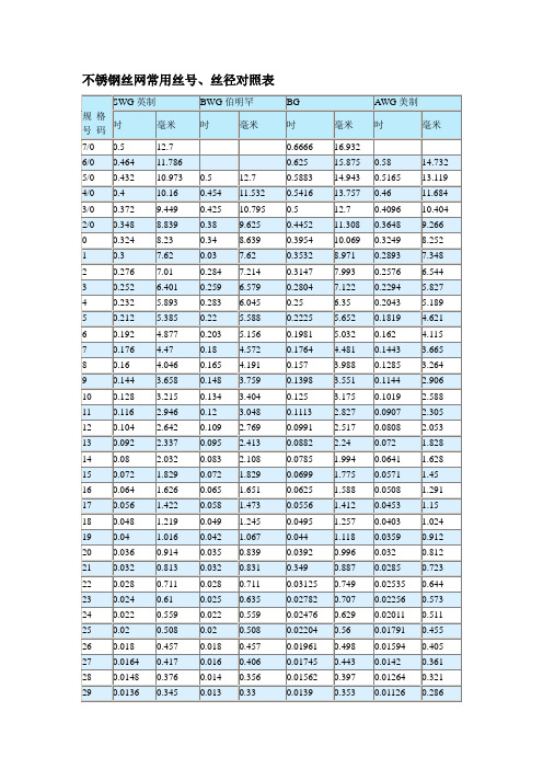
不锈钢丝网常用丝号、丝径对照表不锈钢网常见规格及技术参数:不锈钢丝网目数、丝径、孔径互算公式:目数=25.4÷(孔径mm+丝径mm)孔径mm=25.4÷目数-丝径mm丝径mm=25.4÷目数-孔径mm什么叫目数目数和毫米属于不同的量纲,所以直接比较没有意义。
“目数”是丝网的规格单位,是指1 英寸(25.4毫米)的长度上,有多少个孔目。
而毫米就是一个简单的长度单位。
由于丝网制作有相应的技术标准,不同大小的目数的丝网有规定的金属丝的直径,所以简单的说出不同目数的丝网,每一个孔不算金属丝的实际毫米数,不是行业内的人,是说不出来的。
目前国际上通用的是泰勒标准筛,所谓的多少目是指在每英寸(一个规定的单位长度 2.54厘米)的长度上有多少筛孔,如果有100个孔,就是100目筛,孔数越多,孔眼也就越小。
但由于制作材料不同,比如有不锈钢筛、尼龙筛、铜筛等,它们的粗细不同,所以同是100目筛地话,大小实际上也有区别什么叫丝径1毫米=100 丝(道)“丝”是机械工人对0.01 毫米的俗称,有上海技术传承的工人说“丝”,在北方就把0.01 毫米说成“道”的多,这两种说法在行业内都明白。
丝也叫道,不是单位制中的丝米。
习惯上所称的丝即忽米,1丝=0.01毫米=0.00001米=10微米什么是开孔率开孔率是指筛面的有效面积,也就是指筛面上筛孔的面积总和与筛面总面积的比值,开孔率越高,处理能力越大,筛分效率越高。
线径--就是线材的直径;经线--所有的纵向编织线;纬线--所有的横向编织线;目数--1英寸长度内网孔的个数;密度--1厘米长度内网孔的个数网孔--两经丝或两纬丝之间的距离公差--综平角时,综片处的经线与公差线的垂直距离(MM)公线--过前后胸果(罗拉)的连线上公差--综平时综片处的经线高于公差线下公差--低于公差线叫下公差零公差--与公差线重合叫零公差综角--综框开口后,上综与下综的距离平角--(变角时间)--综平时,钢筘距长纬点的距离各种丝网的网重及成本计算公式不锈钢网计算公式:网重KG =1/2×丝径×丝径×目数×长×宽价格核算=1/2×丝径×丝径×目数×长×宽×丝价+工时费+流通费电焊网重量计算公式:1寸*1寸丝径*丝径*宽*长÷2=KG1寸*1/2 丝径*丝径*宽*长÷4*3=KG1/2*1/2 丝径*丝径*宽*长=KG1/3*1/3 丝径*丝径*宽*长*3*0.48=KG1/4*1/4 丝径*丝径*宽*长*2= KG3/4*3/4 丝径*丝径*宽*长÷3*2=KG3/8*3/8 丝径*丝径*宽*长*1.35=KG5/8*5/8 丝径*丝径*宽*长÷5*8÷2=KG2寸*4寸丝径*丝径*宽*长÷4*0.75=KG铜网重量计算公式:丝径*丝径*目数*宽*长÷2*1.07=KG席形网计算公式:纬丝径*纬丝径*纬目数*宽*长÷4+经丝径*经丝径*经目数*长*宽÷4=KG轧花网重量计算公式:2.54÷(丝径+孔径)=目数然后按照不锈钢网的计算方式计算,另外加2%~5%~9%弯曲度既为重量床面网的计算方法:平米重(kg)=丝径×丝径×(穿条根数×螺距)成本(元)=平米重×长×宽×丝价+穿条价脚踏网的计算方法:每块网重=丝径×丝径×(2.54÷孔径) ×6.28+边米长×0.35 (此公式为保守算法)养猪网计算方法:平米重(kg)=1/4×丝径×丝径×[25.4÷(长孔+丝径)+25.4÷(宽孔+丝径)]烧烤网计算方法:销售价:筛网价+铁皮边价(一般为1元)+加工费+流通费输送带网计算方法:平米重(kg)=丝径×丝径×[25.4÷(1/2螺距+丝径)] ÷4×125%+穿条重(注:此算法为保守算法)石油震动筛网计算方法:不锈钢网价+塑料平网价+压边费造纸网计算方法:网重(kg)=1/2 ×丝径×丝径×目数×长×矿筛网价格计算方法:(背宽+0.6)2×[2.54÷(缝+背)] ×0.25=重量×丝价+各种费用黑丝布成本计算方法:1/2×丝径×丝径×目数×丝价+工时费+流通费分样筛成本计算方法:网价(筛底)+框价+盖价+各种费用铁窗纱计算方法:网重(kg)=1/2×丝径×丝径×目数×长×宽成本(元)=网重×丝价+工时费+流通费铝合金窗纱计算方法:网重(kg)=1/2×丝径×丝径×目数×0.3×长×宽成本(元)=网重×丝价+工时费+流通费塑料窗纱计算方法:网重(kg)=丝径×丝径×目数×长×宽÷2÷6。
电缆线规格型号字母代表的意义
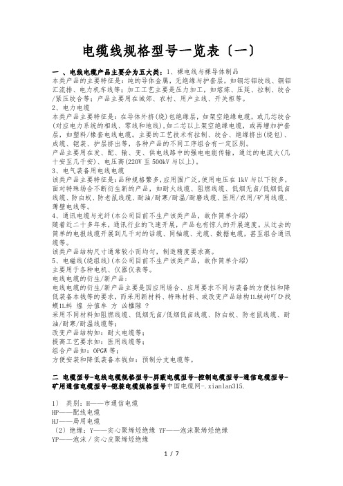
电缆线规格型号一览表〔一〕一、电线电缆产品主要分为五大类: 1、裸电线与裸导体制品本类产品的主要特征是:纯的导体金属,无绝缘与护套层,如钢芯铝绞线、铜铝汇流排、电力机车线等;加工工艺主要是压力加工,如熔炼、压延、拉制、绞合/紧压绞合等;产品主要用在城郊、农村、用户主线、开关柜等。
2、电力电缆本类产品主要特征是:在导体外挤(绕)包绝缘层,如架空绝缘电缆,或几芯绞合(对应电力系统的相线、零线和地线),如二芯以上架空绝缘电缆,或再增加护套层,如塑料/橡套电线电缆。
主要的工艺技术有拉制、绞合、绝缘挤出(绕包)、成缆、铠装、护层挤出等,各种产品的不同工序组合有一定区别。
产品主要用在发、配、输、变、供电线路中的强电电能传输,通过的电流大(几十安至几千安)、电压高(220V至500kV与以上)。
3、电气装备用电线电缆该类产品主要特征是:品种规格繁多,应用围广泛,使用电压在1kV与以下较多,面对特殊场合不断衍生新的产品,如耐火线缆、阻燃线缆、低烟无卤/低烟低卤线缆、防白蚁、防老鼠线缆、耐油/耐寒/耐温/耐磨线缆、医用/农用/矿用线缆、薄壁电线等。
4、通讯电缆与光纤(本公司目前不生产该类产品,故作简单介绍)随着近二十多年来,通讯行业的飞速开展,产品也有惊人的开展速度。
从过去的简单的电报线缆开展到几千对的话缆、同轴缆、光缆、数据电缆,甚至组合通讯缆等。
该类产品结构尺寸通常较小而均匀,制造精度要求高。
5、电磁线(绕组线)(本公司目前不生产该类产品,故作简单介绍)主要用于各种电机、仪器仪表等。
电线电缆的衍生/新产品:电线电缆的衍生/新产品主要是因应用场合、应用要求不同与装备的方便性和降低装备本钱等的要求,而采用新材料、特殊材料、或改变产品结构⒒蛱岣吖ひ找蟆⒒蚪煌分值牟方凶楹隙 ?采用不同材料如阻燃线缆、低烟无卤/低烟低卤线缆、防白蚁、防老鼠线缆、耐油/耐寒/耐温线缆等;改变产品结构如:耐火电缆等;提高工艺要求如:医用线缆等;组合产品如:OPGW等;方便安装和降低装备本钱如:预制分支电缆等。
聚四氟乙烯管材规格表

160×120×100~200
2020/4040
190×160×300
6000
140×55×100
2950
160×140×100~150
1083/1660
200×20×100
7230
140×60×100~150
2889/4340
170×20×100~200
5280/10560
200×60×100~200
1000
110×50×100~150
1740/2610
75×45×100~150
667/1000
90×60×100
813
110×60×100~150
1535/2300
75×50×150
900
90×75×110
490
110×65×100~200
1425/2850
75×55×100~200
470/1000
200×130×100~200
4230/8455
250×60×10
10640
330×110×100
18000
200×140×100~200
3683/7570
250×100×204
19500
500×150×1000
410960
200×150×100~200
3300/6800
250×110×200
18650
1980
110×90×150~200
1130/1520
80×35×100
895
95×45×100~150
1250/1985
120×15×130
3400
80×40×100~150
密度聚乙烯外护管规格表
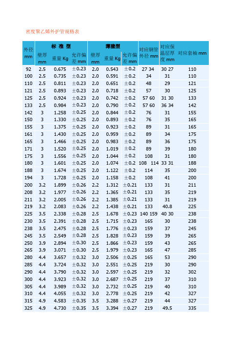
密度聚乙烯外护管规格表说明A.聚乙烯管易老化,如露天存放宜用篷布等物遮盖,堆放处应远离高热源和火源,制成保温管后,禁止暴晒、骤冷,否则聚乙烯管易开裂,影响产品性能和使用寿命。
B.运输和穿管过程中,应避免野蛮装卸,挂钩过细、过硬、用力过猛,否则易造成聚乙烯管摔坏、划伤或撕裂。
C.管材壁厚可调整,壁厚、颜色可按用户要求生产,因管材壁厚不同,保温层厚度为约数,应按实际厚度计算。
D.与管材配套的支架、塑料塞、两头法兰盘,焊条、焊枪、热缩带等齐全。
E.表中的允许偏差是按CJ/114-2000行业标准制定的。
计算公式为:外径≤400mm时,上下偏差之和=0.1×公称壁厚+0.2佳恒预制保温管价格核算示例佳和预制保温管的价格由以下几个部分构成:聚氨酶保温层的成本价、聚乙烯外护管的成本价、钢管的采购价(我们建议需方采购)、加工费(附加10%)和利税(附加1 0%)。
以外径630mm钢管,外径760mm、璧厚11.1mm外护管,聚氨醋保温层53.9mm 为例,每米保温管价格计算如下:1.钢管钢管重量(kg/m)=(外径-壁厚)×壁厚×0.02466(建议用户采购,如果委托我公司采购,按市场价另议)2.外护管 (单价暂时按13800元/吨核算,随市场价格变化双方协商调整):(760-ll.l)×11.1×0.003016×13.8=345.98元/米3.保温层(单价暂时按18000元/吨黑白料核算,随市场价格变化双方协商调整)(737.8-53.9)×53.9×0.0002513×18=166.74元/米4.加工费(345.98+166.74)×10%=51.27元/米5.利税(345.98+166.74)×10%=51.27元/米6.保温管价格(不含钢管)(345.98+166.74+51.27+51.27)=615.26元/米说明: 1.其他规格算法相同,材料价格随市场双方协商调整:2.以上材料按CJ/T114一2000标准质量要求核算,如果用户对材料质量提出特殊要求,按双方商定的材料价格核算。
