UltraScan VIS硬件说明书
uniscanBocIV扫描仪使用说明书

uniscanBocIV扫描仪使用说明书第一部分:产品介绍Uniscan BocIV扫描仪是一款高效、准确的安全评估工具,用于检测网络中的安全漏洞和风险。
本扫描仪具有简单易用的特点,可以帮助用户快速进行安全评估和漏洞修复。
第二部分:使用前的准备1.确保计算机系统符合以下最低要求:- 操作系统:Windows 7或更高版本-内存:4GB或更大-存储空间:至少10GB可用空间-网络连接:稳定的互联网连接-硬件配置:双核处理器或更高版本-打开安装程序并按照指示进行安装。
第三部分:扫描设置1. 启动Uniscan BocIV扫描仪软件- 双击桌面上的Uniscan BocIV图标来启动软件。
2.配置扫描参数-在扫描设置页面,选择要扫描的目标IP地址或域名。
-选择要检测的漏洞类型。
可以选择全面扫描,也可以选择特定类型的漏洞检测。
-根据需要选择扫描深度,以确保您获得准确和详尽的扫描结果。
3.配置HTTP验证-如果需要对目标进行身份验证,可以在HTTP验证选项卡中配置用户名和密码。
-选择使用基本身份验证或表单身份验证,并提供相应的凭据信息。
-如果不需要验证,请留空这些字段。
第四部分:执行扫描1.启动扫描-当您完成扫描设置后,点击“开始扫描”按钮来启动扫描过程。
-扫描过程可能需要一段时间来完成,取决于您的扫描设置和目标的复杂性。
2.查看扫描结果-一旦扫描完成,您可以在扫描结果页面上查看扫描结果。
-所有的漏洞和风险都将被列出,并按严重性进行分类。
-您可以根据需求对结果进行过滤和排序。
3.分析和修复漏洞-分析扫描结果,根据严重性和影响程度来设定修复优先级。
-尽快修复高风险或严重的漏洞,并确保相应的安全措施已经实施。
第五部分:常见问题解答1.为什么我的扫描速度很慢?-扫描速度取决于目标的复杂性、网络连接的稳定性和您的计算机配置。
确保您的网络连接稳定,并且计算机满足扫描软件的要求。
2.如何减少误报?-在扫描设置中,可以对扫描范围进行设置,以便只扫描特定的漏洞类型。
ZEISS VISUMAX 800 眼科仪器说明书

/visumax800ZEISS VISUMAX 800Right on target.Faster. Robotic. Connected.Fast performance.Open more opportunities with confidence.1 VISUMAX 800: CE available for flap cut andSMILE. CE certification for further applications, e.g. ICR, KP and CIRCLE expected in 2022.2 Data on file, narrow spot and track spacing.3 Data on file, myopia with optical zone 6.5 mm.4 Data on file, flap diameter ≤ 8.0 mm,spot distance 4.5 µm, track distance 2.0 µm.VISUMAX ® 800 from ZEISS 1 lets you create a comfortable patient experience and gain confidence in your workflow. It represents a new evolution of ZEISS femtosecond lasers, offering reduced laser time in comparison to its predecessors while making tissue separation with SMILE ® pro from ZEISS easier than before 2.Increased laser frequency and faster cut speeds.Create the lenticule in less than 10 seconds 3 and complete a flap cut in approximately 5 seconds 4. This performance is driven by a faster laser pulse repetition rate of 2 MHz and an innovative scanner system. All this ensures a very short overall suction time.Shorter suction time and reduced stress.The faster cutting speed leads to a shorter suction time, which reduces the probability of a potential suction loss. This can increase peace of mind and reduce stress for you and your patients during the laser treatment.Rainer Wiltfang, MD, Smile Eyes Augenklinik, Munich Airport, Munich, GermanyThe biggest advantage, I think, is the laser time – 10 seconds 3. It’s unbelievable. For us, the surgeons, and also for the patients. By the time I start talking, it’s done. Brilliant.“Smart robotic assistance.Get in position to take control.Digitally connected workflow.Take advantage of integrated efficiency.Tracking distances positioning made easy.Ultrasound sensors assist in actuating the robotic arms. Integrated top-view, side-view and therapy cameras allow you to intelligently observe the surgical environment between device and patient. You are able to observe the patient with ease and ergonomic comfort while docking the cornea correctly.CentraLign systemfor easy centration with little effort.The CentraLign ® assistant system is a computer-controlled function for easy centration. It uses pupil center and vertex position, giving you full control of centration already during the docking phase. There is no need to shift the cutting pattern after docking.Scan the QR code to watch the simulation.OcuLign systemfor easy cyclotorsion alignment.ZEISS VISUMAX 800 features the intuitive OcuLign ® pattern rotation. The sophisticated yet easy-to-use system automatically re-calculates the treatment pattern and helps to counter cyclotorsion that may occur.Scan the QR code to watch the simulation.The VISUMAX 800 connects seamlessly with different products and solutions from ZEISS. The reliable integration can help you achieve faster procedures and more efficiency in a streamlined workflow while assisting you in reducing sources of error.ZEISS Refractive WorkplaceEasily manage, evaluate, store and transfer data.VISUMAX 800 connects to the powerful Refractive Workplace software 5, which runs on the FORUM ® data management solution from ZEISS. Before and after laser vision correction treatments, all relevant surgical procedure documentation, including all videos, is assigned to each respective patient, and stored after confirmation in ZEISS FORUM. You can streamline your workflow and carry out patient data management and treatment planning from anywhere in your clinic. Additionally, you get support in reducing the amount of administrative tasks performed inthe OR.Easy patient access with comfort and control.From the start of a procedure, ZEISS VISUMAX 8001 makes the surgical experience comfortable and reassuring for everyone in the OR. While patients comfortably lie on the surgical bed, you can access patients without difficulty. And as soon as the patient is situated properly, the arm required can be brought into working position – either the laser arm or the OPMI arm for manual surgery.Intelligent robotic assistant systems, such as cyclotorsion and centration aid, can help in enhancing control during your procedures. In every way, the device has been designed to deliver state-of-the-art performance that adds efficiency and ergonomics.5 CE certification Refractive Workplace planned in 2022.Streamline your refractive workflow.The new ZEISS Corneal Refractive Workflow offers a digital connected infrastructure and improves efficiency with the right solution for any eligible patient.ZEISS Refractive WorkplaceRefractive Workplace 5 with connectivity to FORUM is the treatment planning software for our refractive lasers. It offers comprehensive remote planning outside the OR with the option to align integrated diagnostic data. The remote planning station supports an efficient workflow and comfortable treatment strategy.ZEISS Patient Communication Materials Helping you to interact with patients at each step of the patient journey for better understanding of treatment options and expectation management.ZEISS Practice DevelopmentOur ZEISS Practice Development consultants will provide you with an unbiased evaluation of the patient experience in your clinic and collaborate with you to define improvements tailored to your specific needs.ZEISS VISUMAX 800 – MEL 90 combinationThe digital connection of the VISUMAX 800 femtosecond laser 1 and MEL 90 excimer laser 6 to FORUM gives you the freedom for easy remote treatment planning via ZEISS Refractive Workplace. The combination allows you to perform a broad range of laser vision corrections: Lenticule Extraction with ZEISS SMILE pro, Femto-LASIK, PRK/LASEK, and ZEISS PRESBYOND up to 500 Hz repetition rate.ZEISS VISULYZE 7The software VISULYZE ® from ZEISS provides a clear overview of your clinical results and generates nomograms customized to each user with a simple and intuitive interface. The comprehensive software collects, stores and statistically analyzes your own clinical data in a standardized way – helping you to examine and verify refractive outcomes.6 C E certification for MEL 90 and connectivity toFORUM expected in 2022.7 C E certification for VISULYZE in progress.Building on an already groundbreaking system.Additional highlights and accessories of our new evolutionfemtosecond laser.SMILE profor Lenticule Extraction.With SMILE® pro, the ZEISS VISUMAX 800 offers Lenticule Extraction1 for patients with myopia andastigmatism. During the procedure a lenticule is created inside the cornea. The lenticule is subsequentlyextracted through a small incision, thereby achieving the desired vision correction.Flap cutfor Femto-LASIK.For treatments such as Femto-LASIK, the ZEISS VISUMAX 800 delivers highly precise flaps1. Everysurgeon has the opportunity to use their preferred flap configuration. This creates the possibility ofwidely adjustable flap diameter, thickness, hinge position and side cut angle. Thanks to the high cuttingprecision, the flap lift is easy to perform, facilitated by the high cutting speed and optimized parametersettings.Tunnel incisionsfor ICR.The femtosecond laser technology of the ZEISS VISUMAX 800 is also ideally suited to create incisions1 inpreparation for intracorneal ring (ICR) implantations. It provides the possibility of creating corneal tunnelsquickly, precisely and with a high degree of flexibility. When defining tunnel parameters, it even performsinclined cutting geometries and full circle tunnels as well as tunnel segments of 90 to 270°. This allowsthe implantation requirements of various kinds of ring segments to be met.Keratoplasty optionfor corneal transplant.With the Keratoplasty option1, the ZEISS VISUMAX 800 covers several corneal transplant procedures.It enables smooth lamellar and circular incisions for Penetrating Keratoplasty (PKP) and Anterior LamellarKeratoplasty (ALK). High-precision cutting quality and a rapid incision speed enable the efficientpreparation of precision corneal grafts and recipient corneas.The practical Keratoplasty adapter provides a robust and sterile work surface for preparing corneal graftsand the specially designed curved contact glass (type KP) prevents unnecessary compression of thecorneal tissue.CIRCLEfor retreatment.In rare cases when a retreatment may be necessary, the software option CIRCLE from ZEISS1 convertsthe initial cap created with SMILE or SMILE pro into a flap. The actual retreatment is then performed asa LASIK procedure, e.g. with the ZEISS MEL 90.Interactive touchscreensa smart unit.While smart robotic features continuously monitor the patient’s position and makeautomatic adjustments, the interactive touchscreen and intuitive software assist thesurgeon and the assistant at every step throughout the procedure.Surgical microscope and digital video camerafor brilliant visual control.The integrated high-quality ZEISS surgical microscope ensures precise and completevisual control during every manual surgical manipulation. It offers 5 magnificationsteps and it additionally includes a digital video camera for recording surgicalprocedures.Integrated slit projectorfor reassurance right on the spot.As a universal workstation for corneal refractive surgery, the system features anintegrated slit illumination with two different slit widths for immediate checking –without the patient needing to be moved.Operating tableGenius Eye ZThe headrest of the operating table “Genius Eye Z” can be adjusted in threedimensions to account for anatomic specifics of your patients. You can also re-adjust the patient position thanks to the automatic length adjustment of the headshell. Legroom and easy access for the surgeon provide comfortable workingergonomics. The Keratoplasty adapter perfectly fits to the operating table.Surgeon’s chairBalance SupremeThe arm rests of the surgeon’s chair “Balance Supreme” can be swivelled forward andbackward in addition to the height adjustment and rotation adjustment. Also, back rest aswell as height and inclination of the sitting surface can be adjusted for an ergonomic positionduring the surgery.Technical DataLaser type Femtosecond laserAvailable treatment options Flap, SMILE® pro, CIRCLE, ICR, Keratoplasty1 Digital assistant systems Centration aid CentraLign®Cyclotorsion adjustment OcuLign®import of VISULYZE® user nomograms Optical dataMaximum laser repetition2 MHzf requencyWavelength1043 nmSurgical microscopeMagnification0.7×Factors for magnification change0.4 / 0.6 / 1.0 / 1.6 / 2.5Eyepiece magnification12.5× (10×)Filters blue, barrier filter (yellow)Slit ilumination slit width ≤ 0.3 mm / 0.7 mmslit height 11.0 mmAmbient conditions for operationTemperature+18 °C to +25 °CHumidity30 % to 70 %Device mass520 kgMinimum floor load 2.5 kN/m2Footprint standalone L × W: 1,710 mm × 925 mme n -I N T _34_010_0027I P r i n t e d i n G e r m a n y . C Z -X /2021 I n t e r n a t i o n a l e d i t i o n : O n l yf o r s a l e i n s e l e c t e d c o u n t r i e s .T h e c o n t e n t s o f t h e b r o c h u r e m a y d i f f e r f r o m t h e c u r r e n t s t a t u s o f a p p r o v a l o f t h e p r o d u c t o r s e r v i c e o f f e r i ng i n y o u r c o u n t r y . P l e a s e c o n t a c t o u r r e g i o n a l r e p r e s e n t a t i v e s f o r m o r e i n f o r m a t i o n . S u b j e c t t o ch a n g e si n d e s i g n a n d s c o p e o f d e l i v e r y a n d d u e t o o n g o i n g t e c h n i c a l d e v e l o p m e n t . V I S U M A X , S M I L E , C I R C L E , C e n t r a L i g n , O c u L i g n , M E L , P R E S B Y O N D , R e f r a c t i v e W o r k p l a c e , F O R U M a n d V I S U L Y Z E a r e e i t h e r t r a d e m a r k s o r r e g i s t e r e d t r a d e m a r k s o f C a r l Z e i s s M e d i t e c A G o r o t h e r c o m p a n i e s o f t h e Z E I S S G r o u p i n G e r m a n y a n d /o r o t h e r c o u n t r i e s . © C a r l Z e i s s M e d i t e c A G , 2021. A l l r i g h t s r e s e r v e d .Carl Zeiss Meditec AG Goeschwitzer Strasse 51–5207745 Jena Germany//med/contacts0297VISUMAX 8001MEL 906FORUM。
施耐德电气 Unity Quantum 硬件说明书

Unity Quantum 硬件参考手册2文档汇编介绍本套资料包括以下手册:z《Quantum 硬件参考手册》z《Quantum 离散量模块与模拟量I/O模块参考手册》z《Quantum 专用模块与通讯参考手册》z《PLC系统接地与电磁兼容性用户手册》z《984 800 系列I/O参考手册》345目录安全信息 . . . . . . . . . . . . . . . . . . . . . . . . . . . . . . . . . . . . . . . . . . . .9关于手册 . . . . . . . . . . . . . . . . . . . . . . . . . . . . . . . . . . . . . . . . . . .11第 I 部分介绍 . . . . . . . . . . . . . . . . . . . . . . . . . . . . . . . . . . . . . . . . . . 15第 1 章系统 . . . . . . . . . . . . . . . . . . . . . . . . . . . . . . . . . . . . . . . . . . . . . . .17概述 . . . . . . . . . . . . . . . . . . . . . . . . . . . . . . . . . . . . . . . . . . . . . . . . . . . . . . . . . . 17系统概述 . . . . . . . . . . . . . . . . . . . . . . . . . . . . . . . . . . . . . . . . . . . . . . . . . . . . . . . 18典型的 Quantum 系统配置 . . . . . . . . . . . . . . . . . . . . . . . . . . . . . . . . . . . . . . . . . 19第 2 章系统部件 . . . . . . . . . . . . . . . . . . . . . . . . . . . . . . . . . . . . . . . . . . .21概述 . . . . . . . . . . . . . . . . . . . . . . . . . . . . . . . . . . . . . . . . . . . . . . . . . . . . . . . . . . 21控制器模块(CPU) . . . . . . . . . . . . . . . . . . . . . . . . . . . . . . . . . . . . . . . . . . . . . . . 22电源模块(CPS). . . . . . . . . . . . . . . . . . . . . . . . . . . . . . . . . . . . . . . . . . . . . . . . . . 23I/O 模块(Dxx ,Axx). . . . . . . . . . . . . . . . . . . . . . . . . . . . . . . . . . . . . . . . . . . . . . 24网络接口模块 . . . . . . . . . . . . . . . . . . . . . . . . . . . . . . . . . . . . . . . . . . . . . . . . . . . 25智能/专用I/O 模块 . . . . . . . . . . . . . . . . . . . . . . . . . . . . . . . . . . . . . . . . . . . . . . 26模拟器(XSM)模块和电池(XCP) . . . . . . . . . . . . . . . . . . . . . . . . . . . . . . . . . . . . 27底板(XBP) 和底板扩展模块(XBE) . . . . . . . . . . . . . . . . . . . . . . . . . . . . . . . . . . . 28I/O 模块的 CableFast 配线电缆 . . . . . . . . . . . . . . . . . . . . . . . . . . . . . . . . . . . . . 29热备系统 . . . . . . . . . . . . . . . . . . . . . . . . . . . . . . . . . . . . . . . . . . . . . . . . . . . . . . . 30第 3 章网络支持 . . . . . . . . . . . . . . . . . . . . . . . . . . . . . . . . . . . . . . . . . . .31概述 . . . . . . . . . . . . . . . . . . . . . . . . . . . . . . . . . . . . . . . . . . . . . . . . . . . . . . . . . . 313.1概要 . . . . . . . . . . . . . . . . . . . . . . . . . . . . . . . . . . . . . . . . . . . . . . . . . . . . . . . . . . 32概述 . . . . . . . . . . . . . . . . . . . . . . . . . . . . . . . . . . . . . . . . . . . . . . . . . . . . . . . . . . 32所支持的网络 . . . . . . . . . . . . . . . . . . . . . . . . . . . . . . . . . . . . . . . . . . . . . . . . . . . 33Quantum 网络接口技术 . . . . . . . . . . . . . . . . . . . . . . . . . . . . . . . . . . . . . . . . . . . 353.2远程I/O(RIO) 和分布式I/O(DIO). . . . . . . . . . . . . . . . . . . . . . . . . . . . . . . . . . . . . 37概述 . . . . . . . . . . . . . . . . . . . . . . . . . . . . . . . . . . . . . . . . . . . . . . . . . . . . . . . . . . 37目录6远程I/O(RIO). . . . . . . . . . . . . . . . . . . . . . . . . . . . . . . . . . . . . . . . . . . . . . . . . . . . 38分布式I/O(DIO) . . . . . . . . . . . . . . . . . . . . . . . . . . . . . . . . . . . . . . . . . . . . . . . . . . 393.3以太网网络接口 . . . . . . . . . . . . . . . . . . . . . . . . . . . . . . . . . . . . . . . . . . . . . . . . . . 40概述 . . . . . . . . . . . . . . . . . . . . . . . . . . . . . . . . . . . . . . . . . . . . . . . . . . . . . . . . . . . 40TCP/IP 以太网 . . . . . . . . . . . . . . . . . . . . . . . . . . . . . . . . . . . . . . . . . . . . . . . . . . . 41Sy/Max 以太网 . . . . . . . . . . . . . . . . . . . . . . . . . . . . . . . . . . . . . . . . . . . . . . . . . . 423.4Modbus/Modbus Plus 网络接口 . . . . . . . . . . . . . . . . . . . . . . . . . . . . . . . . . . . . . 43概述 . . . . . . . . . . . . . . . . . . . . . . . . . . . . . . . . . . . . . . . . . . . . . . . . . . . . . . . . . . . 43概要 . . . . . . . . . . . . . . . . . . . . . . . . . . . . . . . . . . . . . . . . . . . . . . . . . . . . . . . . . . . 44功能 . . . . . . . . . . . . . . . . . . . . . . . . . . . . . . . . . . . . . . . . . . . . . . . . . . . . . . . . . . . 45Modbus 和 Modbus Plus 服务 . . . . . . . . . . . . . . . . . . . . . . . . . . . . . . . . . . . . . . . 463.5现场总线网络接口 . . . . . . . . . . . . . . . . . . . . . . . . . . . . . . . . . . . . . . . . . . . . . . . . 47概述 . . . . . . . . . . . . . . . . . . . . . . . . . . . . . . . . . . . . . . . . . . . . . . . . . . . . . . . . . . . 47INTERBUS (NOA) . . . . . . . . . . . . . . . . . . . . . . . . . . . . . . . . . . . . . . . . . . . . . . . . 48Profibus (CRP). . . . . . . . . . . . . . . . . . . . . . . . . . . . . . . . . . . . . . . . . . . . . . . . . . . 49AS-i (EIA). . . . . . . . . . . . . . . . . . . . . . . . . . . . . . . . . . . . . . . . . . . . . . . . . . . . . . . 50Sercos (MMS) . . . . . . . . . . . . . . . . . . . . . . . . . . . . . . . . . . . . . . . . . . . . . . . . . . . 51第 4 章Quantum 配置 . . . . . . . . . . . . . . . . . . . . . . . . . . . . . . . . . . . . . . 53概述 . . . . . . . . . . . . . . . . . . . . . . . . . . . . . . . . . . . . . . . . . . . . . . . . . . . . . . . . . . . 534.1Quantum 本地I/O、远程I/O和分布式I/O. . . . . . . . . . . . . . . . . . . . . . . . . . . . . . 54概述 . . . . . . . . . . . . . . . . . . . . . . . . . . . . . . . . . . . . . . . . . . . . . . . . . . . . . . . . . . . 54功能 . . . . . . . . . . . . . . . . . . . . . . . . . . . . . . . . . . . . . . . . . . . . . . . . . . . . . . . . . . . 55本地、远程和分布式I/O配置 . . . . . . . . . . . . . . . . . . . . . . . . . . . . . . . . . . . . . . . 564.2Quantum 本地I/O . . . . . . . . . . . . . . . . . . . . . . . . . . . . . . . . . . . . . . . . . . . . . . . . 57概述 . . . . . . . . . . . . . . . . . . . . . . . . . . . . . . . . . . . . . . . . . . . . . . . . . . . . . . . . . . . 57配置 . . . . . . . . . . . . . . . . . . . . . . . . . . . . . . . . . . . . . . . . . . . . . . . . . . . . . . . . . . . 58举例 . . . . . . . . . . . . . . . . . . . . . . . . . . . . . . . . . . . . . . . . . . . . . . . . . . . . . . . . . . . 594.3Quantum 远程I/O(RIO). . . . . . . . . . . . . . . . . . . . . . . . . . . . . . . . . . . . . . . . . . . . 60概述 . . . . . . . . . . . . . . . . . . . . . . . . . . . . . . . . . . . . . . . . . . . . . . . . . . . . . . . . . . . 60单电缆配置 . . . . . . . . . . . . . . . . . . . . . . . . . . . . . . . . . . . . . . . . . . . . . . . . . . . . . 61双电缆配置 . . . . . . . . . . . . . . . . . . . . . . . . . . . . . . . . . . . . . . . . . . . . . . . . . . . . . 624.4Quantum 分布式I/O(DIO) . . . . . . . . . . . . . . . . . . . . . . . . . . . . . . . . . . . . . . . . . . 63概述 . . . . . . . . . . . . . . . . . . . . . . . . . . . . . . . . . . . . . . . . . . . . . . . . . . . . . . . . . . . 63单电缆配置 . . . . . . . . . . . . . . . . . . . . . . . . . . . . . . . . . . . . . . . . . . . . . . . . . . . . . 64双电缆配置 . . . . . . . . . . . . . . . . . . . . . . . . . . . . . . . . . . . . . . . . . . . . . . . . . . . . . 65第 5 章模块配置 . . . . . . . . . . . . . . . . . . . . . . . . . . . . . . . . . . . . . . . . . . . 67概述 . . . . . . . . . . . . . . . . . . . . . . . . . . . . . . . . . . . . . . . . . . . . . . . . . . . . . . . . . . . 67一个本地 QuantumI/O工作站的映射 . . . . . . . . . . . . . . . . . . . . . . . . . . . . . . . . . 68打开参数配置 . . . . . . . . . . . . . . . . . . . . . . . . . . . . . . . . . . . . . . . . . . . . . . . . . . . 70目录第 6 章硬件安装和维护 . . . . . . . . . . . . . . . . . . . . . . . . . . . . . . . . . . . . . .71概述 . . . . . . . . . . . . . . . . . . . . . . . . . . . . . . . . . . . . . . . . . . . . . . . . . . . . . . . . . . 71空间要求 . . . . . . . . . . . . . . . . . . . . . . . . . . . . . . . . . . . . . . . . . . . . . . . . . . . . . . . 72安装支架 . . . . . . . . . . . . . . . . . . . . . . . . . . . . . . . . . . . . . . . . . . . . . . . . . . . . . . . 74模块安装 . . . . . . . . . . . . . . . . . . . . . . . . . . . . . . . . . . . . . . . . . . . . . . . . . . . . . . . 79端子板的安装与拆卸 . . . . . . . . . . . . . . . . . . . . . . . . . . . . . . . . . . . . . . . . . . . . . . 80安装跳线片 . . . . . . . . . . . . . . . . . . . . . . . . . . . . . . . . . . . . . . . . . . . . . . . . . . . . . 82拆卸模块护门 . . . . . . . . . . . . . . . . . . . . . . . . . . . . . . . . . . . . . . . . . . . . . . . . . . . 83第 II 部分控制器模块(CPU). . . . . . . . . . . . . . . . . . . . . . . . . . . . . . . . .85第 7 章概要 . . . . . . . . . . . . . . . . . . . . . . . . . . . . . . . . . . . . . . . . . . . . . . .87概述 . . . . . . . . . . . . . . . . . . . . . . . . . . . . . . . . . . . . . . . . . . . . . . . . . . . . . . . . . . 87CPU 概述 . . . . . . . . . . . . . . . . . . . . . . . . . . . . . . . . . . . . . . . . . . . . . . . . . . . . . . 88机器停机代码 . . . . . . . . . . . . . . . . . . . . . . . . . . . . . . . . . . . . . . . . . . . . . . . . . . . 89第 8 章低端 CPU . . . . . . . . . . . . . . . . . . . . . . . . . . . . . . . . . . . . . . . . . . .93概述 . . . . . . . . . . . . . . . . . . . . . . . . . . . . . . . . . . . . . . . . . . . . . . . . . . . . . . . . . . 93介绍 . . . . . . . . . . . . . . . . . . . . . . . . . . . . . . . . . . . . . . . . . . . . . . . . . . . . . . . . . . 94前面板开关 . . . . . . . . . . . . . . . . . . . . . . . . . . . . . . . . . . . . . . . . . . . . . . . . . . . . . 95后面板开关 . . . . . . . . . . . . . . . . . . . . . . . . . . . . . . . . . . . . . . . . . . . . . . . . . . . . . 98钥匙开关 . . . . . . . . . . . . . . . . . . . . . . . . . . . . . . . . . . . . . . . . . . . . . . . . . . . . . . . 99Modbus 连接器 . . . . . . . . . . . . . . . . . . . . . . . . . . . . . . . . . . . . . . . . . . . . . . . . . 101指示灯 . . . . . . . . . . . . . . . . . . . . . . . . . . . . . . . . . . . . . . . . . . . . . . . . . . . . . . . . 103Unity Pro 配置对话框 . . . . . . . . . . . . . . . . . . . . . . . . . . . . . . . . . . . . . . . . . . . . 106140 CPU 311 10 技术规格 . . . . . . . . . . . . . . . . . . . . . . . . . . . . . . . . . . . . . . . . 116140 CPU 434 12A 技术规格 . . . . . . . . . . . . . . . . . . . . . . . . . . . . . . . . . . . . . . . 118140 CPU 534 14A 技术规格 . . . . . . . . . . . . . . . . . . . . . . . . . . . . . . . . . . . . . . . 121第 9 章高端 CPU . . . . . . . . . . . . . . . . . . . . . . . . . . . . . . . . . . . . . . . . . .125概述 . . . . . . . . . . . . . . . . . . . . . . . . . . . . . . . . . . . . . . . . . . . . . . . . . . . . . . . . . 125使用 Unity 140 CPU 671 60 模块的 Modicon Quantum 热备系统概述 . . . . . . . 126介绍 . . . . . . . . . . . . . . . . . . . . . . . . . . . . . . . . . . . . . . . . . . . . . . . . . . . . . . . . . 128高端 CPU 的存储卡 . . . . . . . . . . . . . . . . . . . . . . . . . . . . . . . . . . . . . . . . . . . . . 131安装/拆卸高端 Quantum CPU 上的 PCMCIA 存储扩展卡 . . . . . . . . . . . . . . . 133利用键盘,操作Modicon Quantum 热备系统 . . . . . . . . . . . . . . . . . . . . . . . . . 138指示器 . . . . . . . . . . . . . . . . . . . . . . . . . . . . . . . . . . . . . . . . . . . . . . . . . . . . . . . . 140利用液晶显示屏,操作 Modicon Quantum热备系统 . . . . . . . . . . . . . . . . . . . . . . . . . . . . . . . . . . . . . . . . . . . . . . . . . . . . . . 1427目录8访问基本配置 . . . . . . . . . . . . . . . . . . . . . . . . . . . . . . . . . . . . . . . . . . . . . . . . . . 151140 CPU 651 50 技术规格 . . . . . . . . . . . . . . . . . . . . . . . . . . . . . . . . . . . . . . . . 152140 CPU 651 60 技术规格 . . . . . . . . . . . . . . . . . . . . . . . . . . . . . . . . . . . . . . . . 154Modicon Quantum 热备系统(使用 Unity)的 140 CPU 671 60 技术规格 . . . . . 156附录 F机构认证与保护涂层 . . . . . . . . . . . . . . . . . . . . . . . . . . . . . . . . . 159概述 . . . . . . . . . . . . . . . . . . . . . . . . . . . . . . . . . . . . . . . . . . . . . . . . . . . . . . . . . . 159机构认证:电源 . . . . . . . . . . . . . . . . . . . . . . . . . . . . . . . . . . . . . . . . . . . . . . . . . 160机构认证:CPU. . . . . . . . . . . . . . . . . . . . . . . . . . . . . . . . . . . . . . . . . . . . . . . . . 161机构认证:I/O . . . . . . . . . . . . . . . . . . . . . . . . . . . . . . . . . . . . . . . . . . . . . . . . . . 162机构认证:DIO 分站 . . . . . . . . . . . . . . . . . . . . . . . . . . . . . . . . . . . . . . . . . . . . . 165机构认证:RIO 主站和分站 . . . . . . . . . . . . . . . . . . . . . . . . . . . . . . . . . . . . . . . 166机构认证:NOA. . . . . . . . . . . . . . . . . . . . . . . . . . . . . . . . . . . . . . . . . . . . . . . . . 167机构认证:NOE. . . . . . . . . . . . . . . . . . . . . . . . . . . . . . . . . . . . . . . . . . . . . . . . . 168机构认证:NOM 和 NOL . . . . . . . . . . . . . . . . . . . . . . . . . . . . . . . . . . . . . . . . . . 169机构认证:运动模块. . . . . . . . . . . . . . . . . . . . . . . . . . . . . . . . . . . . . . . . . . . . . 170机构认证:电池及模拟器模块 . . . . . . . . . . . . . . . . . . . . . . . . . . . . . . . . . . . . . . 171附录 G系统技术规格 . . . . . . . . . . . . . . . . . . . . . . . . . . . . . . . . . . . . . . 173概述 . . . . . . . . . . . . . . . . . . . . . . . . . . . . . . . . . . . . . . . . . . . . . . . . . . . . . . . . . . 173机械和电气技术规格. . . . . . . . . . . . . . . . . . . . . . . . . . . . . . . . . . . . . . . . . . . . . 174电源技术规格 . . . . . . . . . . . . . . . . . . . . . . . . . . . . . . . . . . . . . . . . . . . . . . . . . . 175I/O模块技术规格 . . . . . . . . . . . . . . . . . . . . . . . . . . . . . . . . . . . . . . . . . . . . . . . . 176工作和存储条件 . . . . . . . . . . . . . . . . . . . . . . . . . . . . . . . . . . . . . . . . . . . . . . . . . 1779安全信息重要信息使用须知在对相关装置进行安装、操作或维护之前,应对照本设备,仔细阅读相关操作规程,以便熟悉该装置。
清华紫光A690用户手册
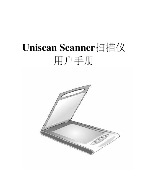
Uniscan Scanner扫描仪用户手册目录一、 扫描仪的安装与设定 (1)设备清点 (1)安装与设定扫描仪 (2)步骤一: 扫描仪保护锁..................................................................... (2)步骤二: 安装软件 (3)步骤三: 连接您的扫描仪和计算机 (5)测试扫描仪 (5)二、 扫描仪的使用与维护 (7)使用扫描仪上的功能按键 (7)Mail电子邮件按键 (7)Scan扫描按键 (7)OCR文字识别按键 (8)Copy复印按键 (8)维护 (9)三、 设定扫描仪按键 (10)设定【文件】按键 (10)设定【应用程序】按键 (11)设定【传真】按键 (12)设定【邮件】按键 (13)设定【复印】按键 (14)设定【文字识别】按键 (15)设定【设置】按键 (16)四、Twain界面 (17)Primary 模式 (17)Advance模式 (19)附录:规格 (27)一、扫描仪的安装与设定设备清点:安装该型号扫描仪前,请确定所有的附件都齐全:1平台式扫描仪2接口电缆3电源适配器4紫光金牌三包凭证5快速安装指南6扫描仪驱动程序,用户手册及图像处理软件光盘一张7 合格证8 可选透扫适配器安装与设定扫描仪步骤一: 扫描仪保护锁您所购买的扫描仪设计有一保护锁,用于搬运过程中保护光学组件。
此保护锁开关位于扫描仪机体的正下方(如图)。
注意:1. 请确认在开始扫描工作或设定前,扫描仪是平稳的放在平面上,开始扫描前,请确定保护锁位于开锁状态(见图1)。
图1 图22. 在搬动扫描仪前,请务必先关机,再将保护锁推到锁定位置(见图2),以避免搬运过程中对扫描仪内部光学组件造成伤害。
3.该型号扫描仪是USB接口扫描仪,用户请注意:请先安装驱动软件再安装硬件。
步骤二: 安装软件在PC(MS Windows 系统)操作系统下的安装: 将扫描仪驱动程序放入光驱,安装光盘将自动运行,并弹出安装界面。
奥视威 BM-U 4K技监级高清视频监视器 使用说明书
使用说明书感谢您选择奥视威电子产品使用前请仔细阅读本说明书Ver:A产品的任何内部技术(包括硬件设备,软件设计,产品商标)均得到法律保护,任何侵犯本产品知识产权的行为,均将追究其法律责任。
本产品中所有本公司的品牌和商标均受到法律保护,产品中所有涉及到的其他公司的品牌和商标均受到其拥有者的法律保护。
为了更好地为广大用户服务,本公司产品将持续改进和发展,本公司保留在不预先通知的情况下对本手册所述的产品进行修改和改进的权利。
本产品的质保期限为两年,以下情况不在质保范围内:⑴ 外观磨损、液晶面板等人为损坏;⑵ 液晶面板的亮点或暗点数量在三个以内;⑶ 使用非产品配套的电源适配器而导致产品损坏;⑷ 未按说明书要求使用、维护、保管导致的产品故障或损坏;⑸ 用户在使用过程中自行拆开产品;⑹ 其他非产品本身设计、技术、制造、质量等问题而导致的故障或损坏。
* 任何销售人员无权提供本条款以外的额外质保。
用户在 使用过程中发现问题或是对我们的产品有建议和要求,请通过电话、传真、电子邮件等方式与我们联系。
声 明南京奥视威电子科技股份有限公司地址:南京经济技术开发区恒通大道10号 210038电话:************传真:************Email:***********http://※ 本说明书适用于BM-U (5代)所有型号的监视器,示意图以BM-U325的外观图为例。
任何规格、 外观上的不同,本说明书都会附加文字说明。
维护注意事项警 告1、为了减少火灾和触电的危险,切勿让本机受雨淋或放置在潮湿的地方。
2、在产生强磁场的设备附近使用时,可能引起视频和音频信号中的噪声,请远离。
电源使用注意事项1、请使用原厂指定的专用电源适配器,以避免造成产品损坏。
2、如果使用其他直流电源,应保证电压范围、供电功率、电源极性符合要求。
3、在下列情况下,请拔下本产品的电源线和外接电池:(A)、如果您很长一段时间不使用本产品。
UV-VIS光谱传感器产品说明书

ApplicationThe sensor measures the spectral absorption of process liquids in the ultraviolet region of the electromagnetic spectrum.•Measurement of protein concentrations •Chromatography monitoring •Filtration monitoring •Concentration measurement of organic compounds •Detection of aromatesYour benefits•Improved process control and easier quality control thanks to quick and reliable monitoring of product concentration –Measuring range up to 2.5 AU or 50 OD (depending on optical path length)–Measurement of UV absorption at discrete wavelengths between 254 nm and 365 nm –Outstanding filter properties for highest linearity –Direct concurrence with laboratory values –Integrated reference detector for lamp compensation –Gas discharge lamp for long service life and stable measured values •Patented Easycal system (optional)–Cost-effective, time-efficient calibration –Easy, in-line calibration which is traceable to NIST without any liquid standards •FM- and ATEX-approved lamps for applications in the hazardous area •Compliance with life sciences sector thanks to hygienic design and FDA- and USP-compliant sealing materials •High degree of product safety as SIP/CIP-resistant •High product yield thanks to low volume requirements •Maximum durability in all applications owing to wide range of materials and process connections •Can be adapted to process requirements:–Optional air purge ports to prevent the formation of condensate on the optical windows –Optional adjuster for optical path lengthProducts Solutions ServicesTechnical Information OUSAF44Optical sensor combined with the OUA260 flow assembly for the measurement of UV absorptionTI00416C/07/EN/13.1671316935OUSAF442Endress+HauserFunction and system designMeasuring principle Light absorption The measuring principle is based on the Lambert-Beer law.There is a linear dependency between the absorption of light and the concentration of the absorbing substance:A = -logA m = ε . c . OPLA ... absorption, A m ... absorption measured by detector ε ... Extinction coefficient c ... Concentration OPL ... Optical path lengthA light source emits radiation through the medium and the incident radiation is measured on the detector side.Once the light has passed through a filter for wavelength selection, the intensity of the light is determined by a photodiode and converted to a photocurrent.The subsequent conversion to transmission (%) or absorbance units (AU, OD) is performed in the associated transmitter.1Absorption measurement with reference 1Light source 2Optical windows 3Measurement filter 4Measuring detector 5Lens 6Medium flow 7Reference filter 8Reference detectorMeasuring system An optical measuring system comprises:•Sensor (photometer) OUSAF44•Liquiline CM44P transmitter •Cable set CUK80•Assembly to suit the sensor, e.g. OUA260OUSAF44Endress+Hauser 31pipe 5Flow assembly OUA2602Transmitter CM44P 6Sensor: light source (lamp)3Cable set CUK807Cable set CUK804Sensor: detector InputMeasured variableUV absorption Measuring range •0 to 2.5 AU •Max. 50 OD (depending on the optical path length)WavelengthDiscrete wavelength at 254, 280, 295, 302, 313 or 365 nmMore available on request Power supplyElectrical connection The sensor is connected to the transmitter using the pre-terminated or labeled cable set CUK80 (for connection to CM44P) or OUK40 (for connection to CVM40). The terminals and labeling may vary depending on the transmitter in use. The cable set must be ordered separately.OUSAF444Endress+Hauser3OUSAF44 connecting cable ALight source (lamp) power supply B Signals of measurement and reference detectorCable lengthMaximum 100 m (330 ft)Versions for use in hazardous areas Safety instructions for electrical apparatus in explosion-hazardous areas, XA01403CConnecting the detector using a safety barrierThe photometer sensors use silicon photovoltaic cells as detectors which are operated in the current mode. The detectors are intrinsically safe and can be deployed in Zone 1 environments.The safe area is separated from the hazardous area by one safety barrier MTL7760AC.OUSAF44Endress+Hauser 5The safety barrier may only have a very low leak current since the optical signals from the sensor can be in the nanoampere range. Therefore, the sensor cable shield is connected to the ground terminal of the barrier.On delivery, the CUK80 detector cable is permanently wired to the safety barrier. All you have to do is simply connect the individual cable ends to the detector and transmitter.Connecting the hazardous area lamp using a junction boxThe hazardous area lamp (EXP-1) must be connected to the transmitter using a certified junction box.For versions with FM approval, the junction box is included in the delivery and already pre-terminated on the lamp side. You simply have to connect the cable of the transmitter (CUK80)to the terminals of the junction box.For versions with ATEX approval, the junction box is not included in the delivery and it and the cable glands required must be provided by the customer at the place of installation. You must connect the cables entirely on your own (CUK80 of transmitter and lamp cable of photometer sensor).OUSAF446Endress+Hauser5Connecting the hazardous area lamp to CM44P using a junction boxInstallationInstallation instructions6Mounting angles. The arrows indicate the direction of medium flow in the pipe.APreferred mounting angle BOptimum mounting angle CAcceptable mounting angle DMounting angle to be avoided E Forbidden mounting angleOUSAF44Endress+Hauser 7EnvironmentAmbient temperature range 0 to 55 °C (32 to 130 °F)Storage temperature -10 to +70 °C (+10 to +160 °F)Humidity 5 to 95 %Degree of protection IP 65 (NEMA 4) for all optical partsProcessProcess temperature 0 to 90 °C (32 to 194 °F) continuous Max. 130 °C (266 °F) for 2 hoursProcess pressure Max. 100 bar (1450 psi) absolute, depending on the material, pipe size and process connection of the flow assemblyMechanical construction7Sensor module ADimension of lamp, depends on lamp type, see table BDimension of detector, see table C Assembly, see Technical Information for assemblyThe total length of the sensor module is derived from the lengths of the lamp, the detector and the assembly.The dimensions of the OUA260 assembly are provided in Technical Information, TI00418C.‣When connecting the sensor cable, make sure you maintain an additional distance of 5 cm (2")on both the lamp side and the detector side of the sensor.OUSAF448Endress+HauserWeight SensorUV lamp0.58 kg (1.28 lbs)UV lamp with wire-braided cable (1.2 m (4 ft)) and junction box (sensor for hazardous area)3.2 kg (6.66 lbs)Easycal detector0.65 kg (1.43 lbs)Standard detector0.36 kg (0.794 lbs)OUA260 assemblyTC ¼"1.14 kg (2.51 lbs)TC 1"1.39 kg (3.07 lbs)TC 2"1.88 kg (4.15 lbs)TC 4" 3.38 kg (7.45 lbs)MaterialsSensor housingStainless steel 316OUA260 assembly Stainless steel 316, 316L or Kynar or customer-specific material Depends on version Cable connection ends Nickel-plated brassLight source Pre-set, low-pressure mercury lamp Lamp operating life: typically 3000 h, at least 1000 hDetector UV silicon detectors, hermetically sealed Filter Multilayer interference filter, designed for extreme UV conditionsCertificates and approvalsmark Declaration of ConformityThe product meets the requirements of the harmonized European standards. As such, it complies with the legal specifications of the EC directives. The manufacturer confirms successful testing of the product by affixing to it the mark.Ex approvals •ATEX II 2G Ex db IIC T5 Gb •FM Cl.1, Div. 1, Groups B, C, DFDA conformityAll non-metal parts in contact with medium, such as rubber and plastic parts, meet the requirements of FDA 21 CFR 177.2600. The plastic and elastomer parts of the sensor in contact with medium have passed the biological reactivity tests according to USP <87> and <88> Class VI.Ordering informationProduct page /ousaf44Product Configurator On the product page there is a "Configuration" button to the right of the product image.1.Click this button. The Configurator opens in a separate window.2.Select all the options to configure the device in line with your requirements.In this way, you receive a valid and complete order code for the device.OUSAF44Endress+Hauser 93.Export the order code as a PDF or Excel file. To do so, click the appropriate button on the rightabove the selection window.For many products you also have the option of downloading CAD or 2D drawings of the selected product version. To do so, click the "CAD" tab and select the desired file type using drop-down lists.Scope of delivery The scope of delivery consists of the following depending on the version ordered:•sensor •Detector and lamp module without flow assembly or •Detector and lamp module mounted on OUA260 flow assembly •Operating InstructionsIf the sensor is ordered with a transmitter, the complete measuring system is factory-calibrated and shipped as one package.If you have any questions, please contact your supplier or your local sales center.AccessoriesThe following are the most important accessories available at the time this documentation was issued. For accessories not listed here, please contact your service or sales office.Flow assembly OUA260•Flow assembly for hygienic sensors •For sensor installation in pipes •Materials: stainless steel 316, 316L or Kynar (other materials available on request)•Wide variety of process connections and path lengths available •Product Configurator on the product page: /oua260Technical Information TI00418CCable CUK80 cable set •Pre-terminated and labeled cables for connecting analog photometer sensors •Product Configurator on the product page: /cuk80CalibrationOUSAF44 EasyCal retrofit kit •Patented system traceable to NIST for the online calibration of UV absorption sensors •Order numbers:–254 nm: 71210149–280 nm: 71210150–295 nm: 71210156–302 nm: 71210153–313 nm: 71210151–365 nm: 71210152Reference rod Order number: 71108543。
UltraScan VIS硬件说明书
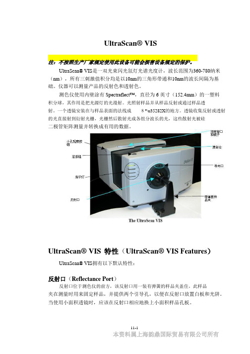
UltraScan® VIS注:不按照生产厂家规定使用此设备可能会损害设备规定的保护。
UltraScan® VIS是一双光束闪光氙灯光谱光度计,波长范围为360-780纳米(nm),所有三刺激值积分均是以10nm的三角形带通和10nm的波长间隔为基础。
仪器可以测量产品的反射色和透射色。
测色仪使用内壁涂有Spectraflect™,直径为 6 英寸(152.4mm)的一塑料积分球,其作用是把光源灯的光漫射。
光照射样品并从样品反射或通过样品透射。
一个透镜安装在与样品表面的法线成8°\u35282X的地方。
透镜收集反射或透射的光直接射到衍射光栅,光栅然后散射光成各组分波长的光,这些散射光被硅二极管矩阵测量并转换成有用的数据。
UltraScan® VIS特性(UltraScan® VIS Features)UltraScan® VIS拥有以下默认特性:反射口(Reflectance Port)反射口位于测色仪的前方,该反射口用一装有弹簧的样品夹盖住,此样品夹在测量时用来固定样品,并提供两个引导孔,以便在反射口放置白板和光阱。
当使用小面积透镜时,应该在反射口相应地换上小面积样品孔板。
11-1本资料属上海韵鼎国际贸易有限公司所有UltraScan® VIS小面积观察(Small Area View)小面积观察可选件包括一个小面积观察透镜和孔板。
小面积观察透镜必须在工厂里安装。
要使用小面积观察可选件:1. 从反射口上取下原来的孔板,用小面积孔板替换。
2. 校正仪器,确信在EasyMatch QC中的设置模式窗口中选择的孔板大小为0.375"(9.525mm),透镜将自动调节。
3. 把样品放在反射口。
4. 确保样品完全覆盖反射口(如果您购买了反光镜用它观察)。
如果需要,调节样品的位置。
5. 测量样品。
注:当使用小面积观察可选件时,每次测量时仪器闪烁多次。
安捷伦uv-vis8453现场培训教材
Agilent 8453UV-VIS 现场培训教材安捷伦科技有限公司生命科学与化学分析仪器部一、培训目的:●基本了解UV-Vis硬件操作。
●掌握化学工作站的开机,关机,参数设定等基本操作。
二、培训准备:1、仪器设备:UV-Vis8453基本操作步骤:(一)、开机:1、打开计算机,进入Windows NT (或Windows 2000)画面,并运行Bootp Server程序。
2、打开UV-Vis8453 电源。
3、待仪器自检完成后,双击Instrument 1 Online图标,化学工作站自动与UV-Vis通讯,进入的工作站画面如下所示。
4、如果仪器没有打开测定样品所需要的灯,则点击Instrument→Lamps→相应的灯→OK或者点击左下角的灯图标,选择相应的灯,并打开。
待仪器氘灯稳定之后,便可测试样品。
(二)使用固定波长模式测定1、选定mode ---> standard模式;2、选定method ---> Fixed Wavelenths3、在固定波长输入对话框内输入测定波长,Display spectrum对话框内输入扫描光谱显示范围4、将比色皿内注入空白溶剂,抬起仪器样品支架锁紧杆,插入比色皿,注意比色皿插入方向,压下锁紧杆。
5、点击空白按钮,或按紫外分光光度计前面板上的空白按钮。
6、记住比色皿方向,拉起样品支架锁紧杆,取出比色皿,倒掉比色皿内液体,用待测液洗比色皿三次以上,注入待测液,用擦镜纸擦干比色皿,按刚才的方向插入比色皿,压下锁紧杆。
7、按sample按钮或按仪器面板上的sample测定样品。
三、保存方法参数1、选定File Save Method As或者点击2、输入文件名,点击OK保存文件。
(如果文件太多,可点Method- Options & Infos 输入简短描述信息。
)四、调用一个方法1、选定File-->Load Method或者点击如下图标2、选定调用的方法,点击OK五、保存数据1保存样品数据选定file→Save→Sample As或者点击图标2、输入文件名,点击OK六、保存选定光谱1、在绘图窗口内选定感兴趣的光谱或者在Sample/Results表内选定2、选定File→Save→Selected Spectra As,输入文件名,点击OK。
UltraScan PRO硬件说明书
UltraScan® PRO操作说明书注:随意抛下仪器或不按照生产厂家规定使用此设备可能会损害设备规定的保护。
注:如果液体溢出或因挥发性液体溢出而起火,有电击危险,当测量液体样品时,小心使用。
UltraScan PRO 是一双光束闪光氙灯光谱光度计,波长范围为 350~1050 纳米(nm),所有三刺激值积分是基于有半带宽为 5nm的三角形带通,并根据ASTM 标准 E308 的 7.3.1 节进行计算。
波长间隔为 5nm。
该测色仪使用内壁涂有 Spectraflect TM,直径为 6"的积分球,从安装的三个闪光氙灯漫射光。
一个灯只提供 UV(紫外)范围的光;一个灯只提供 IR(红外)光;第三个灯提供整个光谱范围的光。
此仪器既可测产品的反射色也可测透射色。
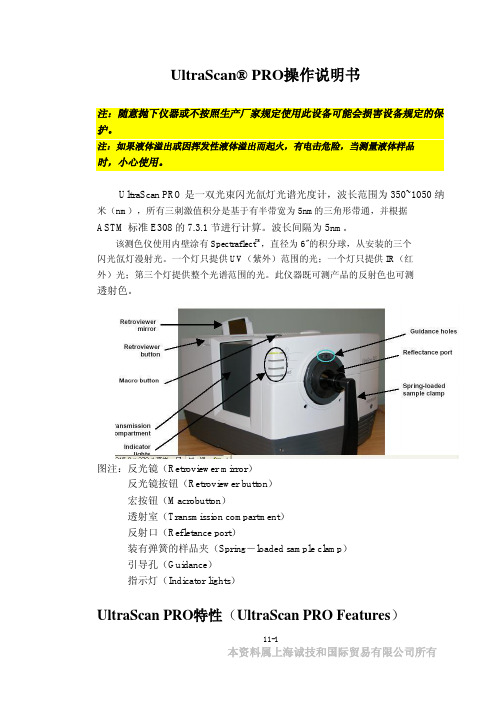
图注:反光镜(Retroviewer mirror)反光镜按钮(Retroviewer button)宏按钮(Macrobutton)透射室(Transmission compartment)反射口(Refletance port)装有弹簧的样品夹(Spring-loaded sample clamp)引导孔(Guidance)指示灯(Indicator lights)UltraScan PRO特性(UltraScan PRO Features)11-1本资料属上海诚技和国际贸易有限公司所有UltraScan PRO 拥有以下默认特性:反射口(Reflectance Port)反射口位于测色仪的前端,该反射口用一装有弹簧的样品夹盖住,此样品夹在测量时用来固定样品,并提供两个引导孔,以便在反射口放置白板和光阱。
样品夹(Sample Clamp)UltraScan PRO包括一装有弹簧的样品夹,能用于把样品平而安全地固定在反射口。
夹有两个按钮,一个可伸起和放下臂,一个可前后移动夹或从反射口移去样品夹。
在样品夹表面有一磁性白陶瓷圆盘为测量提供一致的白背景,也包括一个不滑的黑垫(也是陶瓷的),用于在应用中需要防滑或黑背景时替代白圆盘。
用户手册UltraScope
用户手册RIGOLPublication number ULS-011202August 2002UltraScope For DS3000计算机测控软件© Copyright Rigol Electornic Co. Ltd. 2001All Rights Reserved版权信息1.北京普源精电科技有限公司( RIGOL ELECTRONIC CORP. )版权所有。
2.本公司的产品受已获准及尚在审批的中华人民共和国专利的保护。
3.本手册提供的信息取代以往出版的所有资料。
4.本公司保留改变规格及价格的权利。
注:RIGOL是北京普源精电科技有限公司( RIGOL ELECTRONIC )的注册商标。
Copyright 2001 Rigol Electronic 2UltraScope For DS3000计算机测控软件使用指南Ultrascope For DS3000计算机测控软件简介UltraScope For DS3000系列软件适用于DS3000系列数字存储示波器。
应用此软件可实现计算机与示波器的串口或GPIB通讯,进而实现远程控制。
同时此软件提供了测量、波形、和采样数据的读取功能,方便用户进一步测量和分析信号。
此外,本软件还提供了控制面板设置、波形、测量数据和采样数据的保存及打印等功能。
设备需求最小需求示波器RIGOL DS3000系列PC IBM PC-兼容计算机,Windows 95/98/NT/2000/XP系统16兆内存,4倍速光驱或更好SVGA显示器或更好RS232 电缆注意示波器和PC之间的连接电缆端口要对应GPIB 电缆安装GPIB接卡NI 488.2接卡Copyright 2001 Rigol Electronic 3UltraScope For DS3000计算机测控软件使用指南内容提要本说明书为Ultrascope For DS3000系列操作指南和服务指南,本书共分为四章:第一章:初步了解软件结构主要介绍Ultrascope For DS3000软件各个部分的功能结构,使用户基本认识软件的功能及用法。
ISS-UV VIS 综合采样系统操作指南说明书
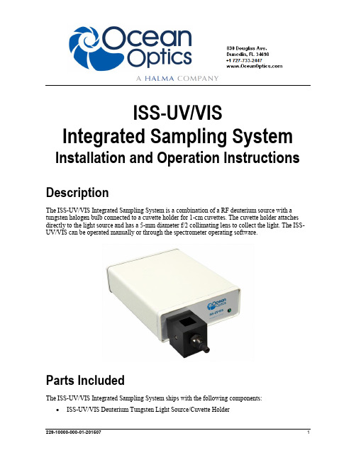
ISS-UV/VIS Integrated Sampling System Installation and Operation Instructions DescriptionThe ISS-UV/VIS Integrated Sampling System is a combination of a RF deuterium source with a tungsten halogen bulb connected to a cuvette holder for 1-cm cuvettes. The cuvette holder attaches directly to the light source and has a 5-mm diameter f/2 collimating lens to collect the light. The ISS-UV/VIS can be operated manually or through the spectrometer operating software.Parts IncludedThe ISS-UV/VIS Integrated Sampling System ships with the following components: ISS-UV/VIS Deuterium Tungsten Light Source/Cuvette HolderISS-UV/VIS Installation and Operation Instructions∙Power cord for connecting the ISS-UV/VIS to outlet∙15-pin accessory cable for software control of the ISS-UV/VISInstalling the Sampling SystemDo not attempt to connect the ISS-UV/VIS to the spectrometer without following the installation instructions in this section. Furthermore, ensure that the spectrometer operating software (e.g., OceanView) is installed on your PC and that the spectrometer is obtaining data before connecting the ISS-UV/VIS.WARNINGS∙The light beam emitted from the ISS-UV/VIS contains ultravioletradiation and can cause eye damage. Never look directly into the lightsource and always use safety goggles when working with this product.∙Dangerous voltage levels are present, and there are no user-serviceable parts. Do not open the unit.∙For any experiments using UV light, we recommend using oursolarization-resistant fiber.∙Contact Ocean Optics for bulb replacement.∙Do not use this instrument for any clinical or diagnosticmeasurements.∙Dropping the unit can cause permanent damage. Handle with care. Adjusting the Fit of the CuvetteThe ISS-UV/VIS is designed to hold 1-cm square cuvettes. When properly adjusted, the cuvette should fit snugly into the holder.►Procedure1.Locate the two ball plunger screws.e a small flathead screwdriver to loosen the two ball plunger screws until the end of eachscrew is visible in the holder.3.Insert a cuvette into the cuvette holder.4.Tighten the ball plunger screws until the cuvette is stationary in the cuvette holder. Do notover-tighten.5.Remove the cuvette from the cuvette holder.ISS-UV/VIS Installation and Operation Instructions Connecting to the Spectrometer►Procedure1. Remove the power from the spectrometer by disconnecting it from the PC or detaching theUSB cable.2.Attach an optical fiber to the SMA connector on the front of the ISS-UV/VIS and attach theother end of this fiber to the SMA connector on your spectrometer.3.Plug the wall transformer into a standard 110 V outlet. Plug the 12 V output into the back ofyour ISS-UV/VIS above the 12V label. For users of European-version wall transformers, plug the transformer into a standard 220 V outlet. At this time, the green LED indicator light on the front of the lamp will be lit. This indicator light only means that the lamp is receiving power, not that the deuterium and tungsten bulbs are on.Operating the ISS-UV/VIS Manually►Procedure1. Find the switch on the back of the ISS-UV/VIS.2.There are three positions: On, Off, and Remote. For Manual operation, move the switch to theOn position. There can be up to a 1.5 second delay between switching the lamp to on and thebulbs igniting. If the lamp has not been used recently, the deuterium bulb may take up to 60seconds to ignite.3.For 0.3% peak-to-peak stability, allow 30 minutes warm-up time before taking yourmeasurements.Operating the ISS-UV-VIS Through Software►Procedure1. Take the 15-pin accessory cable and plug one end into the spectrometer. Connect the other endof the accessory cable into the back of the ISS-UV/VIS.2.Find the switch on the back of the ISS-UV/VIS. There are three positions: On, Off, and Remote.For Software operation, move the switch to the Remote position. Moving the switch to theRemote position enables you to control the lamp through the software.3. Start the operating software.∙For OceanView and SpectraSuite software, check the Strobe/Lamp Enable check box on the on the Acquisition Group Window (OceanView) or Acquisition toolbar (SpectraSuite)to turn the light source in the ISS-UV/VIS on. Uncheck this box to turn the light sourceoff.∙For OOIBase32 software, select Strobe Enable from the OOIBase32 Acquisition Parameters menu bar.∙For OOIChem software, select Spectrometer | Enable Strobe from the menu.ISS-UV/VIS Installation and Operation InstructionsThere can be up to a 1.5 second delay between turning the bulbs on via the software and thebulbs igniting. If the lamp has not been used recently, the deuterium bulb may take up to 60seconds3.For 0.3% peak-to-peak stability, allow 30 minutes warm-up time before taking yourmeasurements.Disabling the Tungsten or Deuterium BulbIt is possible to disable the deuterium or the tungsten bulb in the ISS-UV/VIS. Both bulbs are enabled at the time of manufacture. In order to disable the deuterium or tungsten bulb, you must remove the casing of the ISS-UV/VIS.Disabling the Deuterium BulbIt is possible to enable or disable the deuterium lamp. Jumper block JA of the ISS-UV/VIS's circuit board controls the deuterium bulb.∙Short pins 2-3 (that is, place a jumper over pins 2-3 of JA) to enable the deuterium bulb.∙Short the pins 1-2 (that is, place a jumper over pins 1-2 of JA) to disable the deuterium bulb. Disabling the Tungsten BulbIt is possible to enable or disable the tungsten lamp. Jumper block JB of the ISS-UV/VIS's circuit board controls the tungsten bulb.∙Short pins 2-3 (that is, place a jumper over pins 2-3 of JB) to enable the tungsten bulb.∙Short pins 1-2 (that is, place a jumper over pins 1-2 of JB) to disable the tungsten bulb. Using Solarization-resistant FibersSolarization is the loss of color or transparency in glass due to exposure to ultraviolet radiation. If you are using a UV light source, the UV radiation degrades the silica in a standard patch cord fiber over time, resulting in increased overall absorption values and invalid data. This degradation is called solarization.Our 300-µm Diameter Solarization-resistant Optical Fiber consists of a silica core, surrounded by a silica cladding material. The fiber is then coated in aluminum. Our solarization-resistant fibers are best used for regions below 250 nm, or for applications where exposure to long-term UV light occurs. Replacing the BulbsThe deuterium and tungsten bulbs cannot be replaced by unauthorized personnel. To replace a bulb in the ISS-UV/VIS, contact Ocean Optics.ISS-UV/VIS Installation and Operation Instructions SpecificationsISS-UV/VIS Installation and Operation Instructions。
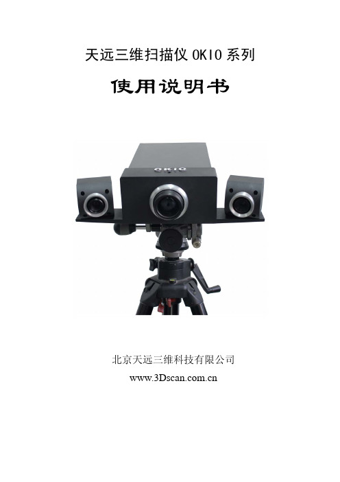
天远三维扫描仪说明书
-II-
天远三维扫描系统 用户使用指南
第一章 引言
1.1 关于天远三维扫描仪
天远三维扫描仪是北京天远三维科技有限公司与清华大学联合开发的、 具有自主知识产权的非接触光学三维扫描仪。
系统具有如下优良特性: 1) 扫描精度高、数据量大,在光学扫描过程中产生极高密度数据; 2) 速度快,单面扫描时间小于 5 秒; 3) 非接触式扫描,适合任何类型的物体,除可以覆盖接触式扫描的适用范
5.1 引言 ………………………………………………………………22
5.2 菜单 ………………………………………………………………25
5.3 工具栏 ……………………………………………………………40
5.4 视窗
……………………………………………………………41
5.5 右键菜单 …………………………………………………………42
表1遥控器按键定义与操作说明按键图案对应快捷键操作说明光笔采集单点2光笔标定中补偿栏中使用对应按键为标志采集图634遥控器实物天远三维扫描系统用户使用指南67后退altb撤消光笔当前采点取位置逗号光笔标定中标定栏中使用对应按键为标志采集撤位置altc撤销取位置中所取得上一次位确定enter确定ctrlshiftc投射十字线ctrlshiftl标志点识别space空格扫描数据等于号拼接当前数据3数字3建立框架ctrlshifto单面扫描保留保留白色大号按键esc保留3使用方法
3.1 三维扫描仪 ……………………………………………………………9
3.2 图像采集 ……………………………………………………………9
3.3 摄像机定标 …………………………………………………………9
3.4 测量模式 …………………………………………………………11
IRISS UltraScan 3000 产品说明书
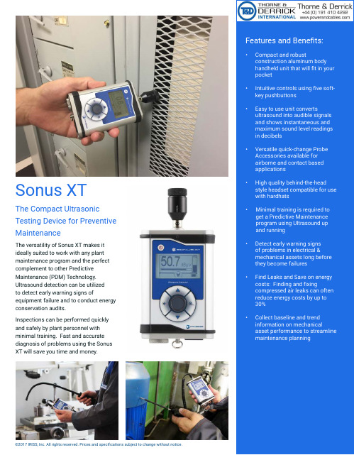
Features and Benefits:•Compact and robustconstruction aluminum body handheld unit that will fit in your pocket•Intuitive controls using five soft-key pushbuttons•Easy to use unit convertsultrasound into audible signals and shows instantaneous and maximum sound level readings in decibels•Versatile quick-change Probe Accessories available for airborne and contact based applications•High quality behind-the-head style headset compatible for use with hardhats•Minimal training is required to get a Predictive Maintenance program using Ultrasound up and running•Detect early warning signs of problems in electrical &mechanical assets long before they become failures•Find Leaks and Save on energy costs: Finding and fixingcompressed air leaks can often reduce energy costs by up to 30%•Collect baseline and trend information on mechanicalasset performance to streamline maintenance planningThe versatility of Sonus XT makes it ideally suited to work with any plant maintenance program and the perfect complement to other Predictive Maintenance (PDM) Technology. Ultrasound detection can be utilized to detect early warning signs ofequipment failure and to conduct energy conservation audits.Inspections can be performed quickly and safely by plant personnel with minimal training. Fast and accurate diagnosis of problems using the Sonus XT will save you time and money.The Compact UltrasonicTesting Device for Preventive MaintenanceSonus XTTechnical DataSonus XT Usages:Quickly and Safely performclosed panel airborne Ultrasound inspections of electrical equipment including Switchgear, Switchboards, Panelboards, Transformers, Motor Control Centers and Process Equipment Panels to detect early warning signs including:• Arcing • Tracking • CoronaWith the optional Parabolic Dish sensor, look for signs of Corona on outdoor utility switchyard equipment including:• Transformers • Insulators• Cut-out SwitchesPerform data based inspections and collect trend information on mechanical assets including:• Bearing Condition • Pump Cavitation • Gear Box• Pumps / MotorsFind Energy Saving opportunities by conducting leak detection and energy audits on:• Compressed Air systems • Vacuum systems • Seals & Gaskets • Condenser Tubes • Hatches • Boilers• Heat Exchangers • Valves• Steam Traps。
并发扫描检测配置手册_20.12
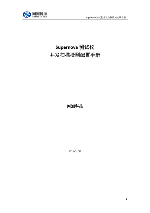
Supernova测试仪并发扫描检测配置手册网测科技2021/01/22目录1.文档说明 (3)2.网络拓扑 (3)3.配置过程 (4)3.1配置受测设备 (4)3.1.1升级特征库版本 (4)3.1.2创建系统漏洞扫描用例 (5)3.2创建并发扫描检测用例 (6)4.运行用例 (7)4.1运行并发扫描检测用例 (7)4.2运行系统漏洞扫描用例 (8)5.监测用例 (8)6.历史报告 (9)6.1查看历史报告 (9)6.2导出报告 (10)1. 文档说明根据国家发布的《网络关键设备和网络安全专用产品目录(第一批)》(/2017-06/09/c_1121113591.htm ),要求网络脆弱性扫描产品最大并行扫描IP 数量大于等于60个,Supernova 系列测试仪并发扫描检测用例,支持对网络脆弱性扫描产品最大并行扫描IP 数量进行检测认证。
检测对象适用于利用扫描手段检测目标网络系统中可能被入侵者利用的脆弱性的软件或软硬件组合。
本文档主要介绍并发扫描检测的配置和测试过程。
随着需求的不断改变,可能会对用例配置进行修改和升级,从而改变配置过程,所以有任何问题,请联系我们的售前或售后支持人员。
2. 网络拓扑Supernova 系列测试仪本身支持系统漏洞扫描功能,故本文档将以一台26E 为受测设备运行系统漏洞扫描用例扫描目标主机、一台20C 为测试设备运行并发扫描检测用例对并发扫描IP 数量进行统计检测为例,说明整个配置和测试过程。
为了便于理解整个配置和测试过程,网络拓扑如下所示:受测设备(SuperNova_16E 系统漏洞扫描)mgmt1:IP 地址192.168.16.216port1:与测试设备的port1接口连接,进行系统漏洞扫描mgmt1port1测试设备(SuperNova-20C 并发扫描检测)mgmt1:IP 地址192.168.16.233port1:与受测设备的port1接口连接,进行并发扫描检测mgmt1port1网关网关工作电脑与测试设备mgmt1网口相通工作电脑与受测设备mgmt1网口相通测试设备port1与受测设备port1连接Port1子网配置:测试仪端口IP地址或范围:17.1.2.2测试仪端口子网掩码:16被扫描主机IP地址或范围:17.1.1.101-17.1.1.160Port1子网配置:网络脆弱性扫描产品端口IP地址或范围:17.1.2.2网络脆弱性扫描产品端口子网掩码:16测试仪端口IP地址或范围:17.1.1.101-17.1.1.160测试仪端口子网掩码:16工作电脑配置用例,监控测试过程,查看报告3.配置过程从第2章的网络拓扑中可以看出,需要在26E(模拟受测设备)上创建一个系统漏洞扫描用例,在20C(测试设备)上创建一个并发扫描检测用例。
UltraScan PRO硬件说明书

UltraScan® PRO操作说明书注:随意抛下仪器或不按照生产厂家规定使用此设备可能会损害设备规定的保护。
注:如果液体溢出或因挥发性液体溢出而起火,有电击危险,当测量液体样品时,小心使用。
UltraScan PRO 是一双光束闪光氙灯光谱光度计,波长范围为 350~1050 纳米(nm),所有三刺激值积分是基于有半带宽为 5nm的三角形带通,并根据ASTM 标准 E308 的 7.3.1 节进行计算。
波长间隔为 5nm。
该测色仪使用内壁涂有 Spectraflect TM,直径为 6"的积分球,从安装的三个闪光氙灯漫射光。
一个灯只提供 UV(紫外)范围的光;一个灯只提供 IR(红外)光;第三个灯提供整个光谱范围的光。
此仪器既可测产品的反射色也可测透射色。
图注:反光镜(Retroviewer mirror)反光镜按钮(Retroviewer button)宏按钮(Macrobutton)透射室(Transmission compartment)反射口(Refletance port)装有弹簧的样品夹(Spring-loaded sample clamp)引导孔(Guidance)指示灯(Indicator lights)UltraScan PRO特性(UltraScan PRO Features)11-1本资料属上海诚技和国际贸易有限公司所有UltraScan PRO 拥有以下默认特性:反射口(Reflectance Port)反射口位于测色仪的前端,该反射口用一装有弹簧的样品夹盖住,此样品夹在测量时用来固定样品,并提供两个引导孔,以便在反射口放置白板和光阱。
样品夹(Sample Clamp)UltraScan PRO包括一装有弹簧的样品夹,能用于把样品平而安全地固定在反射口。
夹有两个按钮,一个可伸起和放下臂,一个可前后移动夹或从反射口移去样品夹。
在样品夹表面有一磁性白陶瓷圆盘为测量提供一致的白背景,也包括一个不滑的黑垫(也是陶瓷的),用于在应用中需要防滑或黑背景时替代白圆盘。
UltraLOG V3 操作说明书2006版
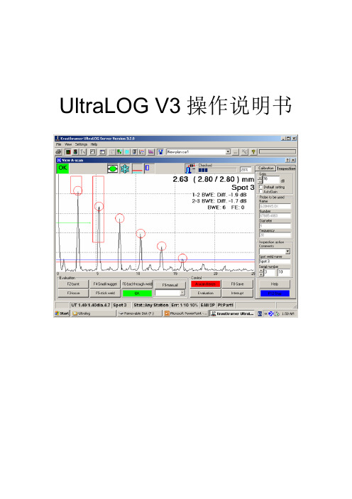
UltraLOG V3操作说明书概述:UltraLOG是一个数据库辅助评估程序,共生在PC Based 数字式超音波探伤机上做点焊(Spot weld)技术之焊点(Nugget)质量检查,UltraLOG可储存、管理检查结果并可辅助检查质量,在此可分成很多质量等级,例如:焊点过小(Small Nugget)、过烧(burnt)、溶入深度不足(incomplete root penetration 或bad through – welding)、脱焊(Loose)…。
使用者可以透过预先建立检查计划(inspection plan)预先定义一系列欲检查的焊点之使用探头设定等,再依计划依序检查并储存结果避免遗失,其检查计划可被重复使用。
UltraLOG程序可在Windows 95/98/NT/2000及XP环境下使用,同时可享有Windows 的标准辅助之便利性。
用户也可加上UltraLOG Database manager程序做结构式检查计划,配合生产在线之车身结构部品名、检查。
组成USLT2000IP硬件组成:1. 工业用携带式计算机。
2. 超音波探伤机电子组成(T/R – BOX)。
3. PC数位卡(PC Digitization card)。
4. 遥控盒附件(Remote control Box)。
5. 超音波探头。
工业用携带式计算机超音波探伤机电子组/ PC数字卡遥控盒附件(Remote control Box)超音波探头USLT2000IP软件组成:1. Windows 操作系统95/98/NT/2000/XP皆可。
2. UltraLOG点焊质量检测辅助判断软件。
3. 选配件UltraLOG Database manager结构式检查计划编辑软件。
UltraLOG点焊质量检测辅助判断软件选配件UltraLOG Database manager结构式检查计划编辑软件计算机硬件说明■右边侧面 / 背面USLT2000卡插槽调制解调器连接器LAN连接器USB连接器DC-IN 外部键盘 / 鼠标连接器音频输出接头话筒输入接头扩张连接器外部显示连接器并行连接器RS-232(遥控接收器输入)为USLT2000所使用之输入端■左侧面 / 前面电源开关软盘驱动器充电电池进入UltraLOG 软件在开机进入Windows 环境后在桌面上点选 图形进入UltraLOG系统。
Wavescan 中文版操作手册

波前像差仪操作手册型号:WaveScan© 该仪器设备2008年版的版权由AMO Manufacturing USA,LLC所有美国印制。
PreVue™、WaveScan WaveFront™标识、WaveScan WaveFront™、WavePrint™和WaveScan™均为AMO公司的商标,该商标已经在美国专利和商标局进行了注册。
CustomVue™、STAR S4™和STAR S4 IR™也为AMO公司的注册商标。
AcuityMap™是20/10 Perfect Vision GmbH的注册商标。
Windows™是美国微软公司的注册商标。
DirectCD™是Roxio公司的注册商标。
WaveScan波前像差仪的设计已获得了相关的专利保护。
在得到AMO Manufacturing USA,LLC的书面授权之前,本出版物的任何部分都不得以任何形式或者通过任何方法,即无论是电子或者机械的方法,包括影印、记录、或者任何信息存储和检索系统进行复制或者传播。
生产企业:AMO Manufacturing USA, LLC注册地址:510 Cottonwood Drive Milpitas, California 95035生产地址:510 Cottonwood Drive Milpitas, California 95035售后服务单位:眼力健(上海)医疗器械贸易有限公司联系方式:86-21-23077666(中国);+1(877)266-4543(美国)注册证编号:国食药监械(进)字2011第2222590号产品标准编号:进口产品注册标准YZB/USA 2945-2011《波前像差仪》如果要在欧洲共同体市场中联系AMO公司,请直接致函:AMO Germany GmbHRudolf‐Plank‐Str. 3176275 EttlingenGermany在欧洲联盟中的报废处理要求准分子激光机系统、WaveScan™系统和裂隙灯中的电子元件和附件以及其他任何以AMO 的名义销售的设备,都严格遵守欧洲联盟关于电气和电子设备(WEEE)报废的规定2002/96/EC。
3U手持式数码显微镜使用说明书

3U手持式数码显微镜PRO-M显微图像分析软件使用说明书台湾三优数位光学股份有限公司目录1.注意事项及软硬件环境 ---------------------------------------------------------------------------------------------- 3 1.1注意事项 ------------------------------------------------------------------------------------------------------------ 31.2软硬件环境 -------------------------------------------------------------------------------------------------------- 32.安装步骤与软件主界面介绍 --------------------------------------------------------------------------------------- 32.1安装步骤 ------------------------------------------------------------------------------------------------------------ 32.2软件主界面说明 ------------------------------------------------------------------------------------------------- 53.菜单功能介绍 ----------------------------------------------------------------------------------------------------------- 63.1文件------------------------------------------------------------------------------------------------------------------- 63.2视图------------------------------------------------------------------------------------------------------------------- 63.3编辑------------------------------------------------------------------------------------------------------------------- 73.4操作------------------------------------------------------------------------------------------------------------------- 73.5设置------------------------------------------------------------------------------------------------------------------- 83.6帮助------------------------------------------------------------------------------------------------------------------- 94 操作说明------------------------------------------------------------------------------------------------------------------ 94.1预览窗口 ------------------------------------------------------------------------------------------------------------ 94.2照片预览窗口 --------------------------------------------------------------------------------------------------- 104.3预览状态栏------------------------------------------------------------------------------------------------------- 114.4常用工具栏: --------------------------------------------------------------------------------------------------- 114.5图像文件夹------------------------------------------------------------------------------------------------------- 114.6文件状态栏------------------------------------------------------------------------------------------------------- 134.7视频回放窗口 --------------------------------------------------------------------------------------------------- 135.测量工具栏的绘图与照片特效处理功能 -------------------------------------------------------------------- 145.1绘图功能 ---------------------------------------------------------------------------------------------------------- 145.2照片效果处理按钮--------------------------------------------------------------------------------------------- 18 6测量功能----------------------------------------------------------------------------------------------------------------- 186.1测量功能使用步骤 -------------------------------------------------------------------------------------------- 186.2直线测量 --------------------------------------------------------------------------------------------------------- 196.3连续线测量 ------------------------------------------------------------------------------------------------------ 196.4半径圆测量 ------------------------------------------------------------------------------------------------------ 206.5直径圆测量 ------------------------------------------------------------------------------------------------------ 206.6三点圆测量 ------------------------------------------------------------------------------------------------------ 216.7三点弧测量 ------------------------------------------------------------------------------------------------------ 216.8角度测量 --------------------------------------------------------------------------------------------------------- 226.9四点角度测量--------------------------------------------------------------------------------------------------- 226.10椭圆测量 -------------------------------------------------------------------------------------------------------- 236.11坐标按钮 -------------------------------------------------------------------------------------------------------- 236.12标尺按钮 -------------------------------------------------------------------------------------------------------- 24 7.测量校正 -------------------------------------------------------------------------------------------------------------- 257.1测量校正原理 --------------------------------------------------------------------------------------------------- 257.2校正使用步骤 --------------------------------------------------------------------------------------------------- 251.注意事项及软硬件环境1.1注意事项○1请勿以手指直接触摸镜头及LED部份, 以免发生危险或招致镜头损坏。
4K Ultra Active 安全摄像头用户手册说明书
2. Cliquer sur le Main Menu, puis cliquer sur l’icône des paramètres (
).
3. Cliquer sur Setting > Display.
4. Cliquer sur l’onglet Display.
5. Dans le menu déroulant Resolution, sélectionnez 3840 x 2160.
6. Cliquer sur Apply pour enregistrer et cliquer sur OK pour confirmer.
Conseils d’installation
• Pointer la caméra dans la direction où il y a le moins d’obstruction (p. ex. : branches d’arbres)
Changer le DVR pour une résolution 4K
La résolution de sortie d’un DVR HD de Lorex est établie à 1080p par défaut. Pour voir la résolution 4K sur un écran 4K, la résolution de sortie doit être changée à l’aide du menu DVR.
- 1、下载文档前请自行甄别文档内容的完整性,平台不提供额外的编辑、内容补充、找答案等附加服务。
- 2、"仅部分预览"的文档,不可在线预览部分如存在完整性等问题,可反馈申请退款(可完整预览的文档不适用该条件!)。
- 3、如文档侵犯您的权益,请联系客服反馈,我们会尽快为您处理(人工客服工作时间:9:00-18:30)。
UltraScan® VIS注:不按照生产厂家规定使用此设备可能会损害设备规定的保护。
UltraScan® VIS是一双光束闪光氙灯光谱光度计,波长范围为360-780纳米(nm),所有三刺激值积分均是以10nm的三角形带通和10nm的波长间隔为基础。
仪器可以测量产品的反射色和透射色。
测色仪使用内壁涂有Spectraflect™,直径为 6 英寸(152.4mm)的一塑料积分球,其作用是把光源灯的光漫射。
光照射样品并从样品反射或通过样品透射。
一个透镜安装在与样品表面的法线成8°\u35282X的地方。
透镜收集反射或透射的光直接射到衍射光栅,光栅然后散射光成各组分波长的光,这些散射光被硅二极管矩阵测量并转换成有用的数据。
UltraScan® VIS特性(UltraScan® VIS Features)UltraScan® VIS拥有以下默认特性:反射口(Reflectance Port)反射口位于测色仪的前方,该反射口用一装有弹簧的样品夹盖住,此样品夹在测量时用来固定样品,并提供两个引导孔,以便在反射口放置白板和光阱。
当使用小面积透镜时,应该在反射口相应地换上小面积样品孔板。
11-1本资料属上海韵鼎国际贸易有限公司所有UltraScan® VIS小面积观察(Small Area View)小面积观察可选件包括一个小面积观察透镜和孔板。
小面积观察透镜必须在工厂里安装。
要使用小面积观察可选件:1. 从反射口上取下原来的孔板,用小面积孔板替换。
2. 校正仪器,确信在EasyMatch QC中的设置模式窗口中选择的孔板大小为0.375"(9.525mm),透镜将自动调节。
3. 把样品放在反射口。
4. 确保样品完全覆盖反射口(如果您购买了反光镜用它观察)。
如果需要,调节样品的位置。
5. 测量样品。
注:当使用小面积观察可选件时,每次测量时仪器闪烁多次。
UltraScan® VIS反光镜(Retroviewer)反光镜是一在积分球内的灯让您在一屏幕上观察当前在反射口的样品,这11-2有助您确定样品的正确测量位置。
要使用它开灯,叙述如下。
在反射口的样品被照亮,一个像出现在反光镜的屏幕上。
如果需要,调节屏幕上的门,使看到屏幕显示的镜像。
反光镜灯必须在工厂安装。
反光镜灯有两种操作模式:1. 测量之间灯一直开着。
2. 每一次测量后,灯关闭。
用反光镜按钮来选择所需的操作模式如下:● 灯一直开模式:一直按住反光镜按钮直到听到“哔”一声。
需要关闭灯时,连续三次按并立即释放反光镜按钮。
● 灯关闭模式:按和立即释放反光镜按钮,当您作测量时灯将自动关闭。
注:为了避免内部热量积聚,此灯在一分钟休止后将自动关闭,而不管您选择的模式如何。
样品夹(Sample Clamp)UltraScan® VIS有一装有弹簧的样品夹,此样品夹用于在反射口平坦而又安全地固定样品。
样品夹上有两个按钮,一个用于竖起和放下样品夹臂,另一个用于向前或向后移动样品夹。
UltraScan® VIS一白色有磁性的陶瓷圆片在样品夹的面上为测量提供一致的白背衬,还有一不光滑的黑垫(也有磁性)用于当需要不滑或黑背衬的应用时,替换白圆片。
要改变衬垫,只需取出白圆片放上不滑垫。
透射室(Transmission Compartment)位于测色仪中部的透射室是用来测量透明固体或液体的透射色的。
当校正和测量时应该关上透射室的门。
111-3本资料属上海韵鼎国际贸易有限公司所有1 此仪器在作反射和透射测量时,关闭透射室门是好习惯,更多信息请见UltraScan® VIS校正节注释。
包括 /去除镜面反射的孔(Specular Included/Excluded Port)UltraScan® VIS积分球上设有一去除镜面反射的孔门,在进行包括镜面反射和透射测量时,关上此门;而在进行去除镜面反射的测量时,则需打开此门。
门的开关位置通过EasyMatch QC控制。
在各种测量模式的更多信息见本章UltraScan® VIS校正节。
除去镜面反射门打开去除镜面反射门关闭自动紫外控制(Automated UV Control)UltraScan® VIS可以进行Ganz-Griesser校正,它使用的是400-nm的紫外滤色片用此来保证紫外光能量与可见光能量的平衡,这提高了仪器间照明光源的一致性并且减少光源老化对颜色的影响,当测量含有荧光成分的样品时需要进行该校正(如荧光增白样品)。
进行Ganz-Griesser校正时需要一块稳定的带有Gans白度值荧光标准白板11-4(该值一般是在除去镜面反射模式下测得的),该值可以追溯到德国Hohenstein 协会的四步棉花白度标尺(The assigned value is traceable to a four-step cotton white scale calibrated by the Hohenstein Institute in Germany).如何使用UV控制见“测色仪菜单”章。
注:知道正测量的样品包含的是哪一类的荧光是重要的,有些材料其荧光是由于可见波长的光激发而不是紫外波长的光激发的,UV吸收滤色片不能消除这类荧光。
指示灯(Indicator Lights)UltraScan® VIS指示灯特性使您知道当前使用的是哪一种校正模式。
顶上的灯亮说明仪器电源开着,第二个灯亮表示去除镜面反射孔是开着的,第三个灯亮说明现正在用小面积观察,而底下的灯亮表示去除UV滤色片100%插入。
宏按钮(Macro Button)宏按钮也称“测色仪按钮”,激活试样测量。
UltraScan® VIS附件(UltraScan® VIS Accessories)UltraScan® VIS系统提供以下放在标准箱里的附件:● 白色校正板――在校正时放在反射口(带有销子插入引导孔)。
此板可追溯到国家物理实验室(NPL)(英国)的原始标准。
● 光阱――在反射模式校正时放在反射口(带有销子插入引导孔)。
11-5本资料属上海韵鼎国际贸易有限公司所有● 黑卡――在透射模式校正时放在透射室。
● 绿板――放在反射口(带有销子插入引导孔),用来校核仪器性能。
● 钕镨滤色片――旋入透镜前,校核波长精度。
● 板数据表――给出标准板的校正信息。
● 样品夹的防滑衬垫――可替换白色圆片放到样品夹上,以适应一些需要防滑或黑色背衬的应用。
● 标准维护卡――指导您如何清洁标准板。
● 保险丝――提供两个备用 3 安培保险丝。
● Allen扳手――提供一个1/8”板手。
● 透镜刷。
● RS-232通信电缆。
● USB通信电缆● 电源线。
● 标准板追踪证书。
● 诊断软件CD。
UltraScan® VIS可选件和样品装置(UltraScan® VIS Options and Sample Devices)为在UltraScan® VIS的测试口放置样品,使仪器易于使用提供许多可选件和装置,任一或所有下列可选件和样品装置可随UltraScan® VIS系统购买。
为您方便定购附HunterLab部件号。
● 脚开关(HL#D02-1010-327)● 压缩夹装置(HL#D02-1011-131)11-6● 纱样夹(HL#02-7396-00)● 带玻璃1"孔扳 (HL#A02-1011-124)● 4-mm孔扳 (HL#A02-1011-184)● 带光罩的反射样品架(HL#B02-1005-172)● 半微量粉末样品架(HL#D02-1012-313)● 小面积观察(包括在CQXE/SAV/UV和CQXE/SAV仪器配置内)● 反光镜(HL#RETRO-CQXE)● 触摸屏(HL#DISPLAY-CQXE)● 脚开关组件(HL#D02-1010-327)● 预制品反射样品架(HL#D02-1011-841)● 透射夹(HL#C02-1005-444)● 透射架 (HL#C02-1005-481)● 比色皿(50-mm比色皿 HL#13-8573-20、33-mm比色皿B04-1003-801、20-mm比色皿 04-4592-00、10-mm比色皿13-8573-40)●● 带两个螺旋盖的比色皿 (10-mm比色皿 HL#D12-1011-893、20-mm 比色皿D12-1011-890 、33-mm比色皿 D12-1011-891、50-mm比色皿D12-1011-892)● 透射溢流盘 (HL#D02-1011-568)● 高比色皿 [3个一套] (HL#B04-1002-672)● 流动液体透射架和比色皿 (透射架HL#D02-1009-960 、50-mm比色皿C04-1001-960 、20-mm 比色皿C04-1001-959、10-mm比色皿C04-1001-958 )● 小体积透射架和10mm小体积比色皿 (透射架HL#CMR2220、比色皿A13-1011-613)● 圆柱形比色皿架 (HL#D02-1011-550)● 半微量比色皿架和光学组件 (HL#L02-1012-202)● 蓝粗纹板组件(HL#D02-1011-085)● 预制品透射样品架(HL#D02-1011-833)脚开关组件(Foot Switch Assembly)按下脚开关和开启测色仪前面的宏开关执行相同的功能。
安装脚开关只要将它插入UltraScan® VIS背面的圆形连接器内。
11-7本资料属上海韵鼎国际贸易有限公司所有压缩夹组件(Compression Clamp Kit)此可选件为UltraScan® VIS提供一压缩夹组件。
该装置的功能是把纤维压缩成一个致密状态,以期得到重复性的颜色分析。
用没有修改的孔板插件和玻璃样品杯也可以用来装地毯、织物和其它软的样品放在反射口带有恒定的压力。
该可选件包括如下组成部分:● 修改的孔插板。
● 为孔盘设置的保护帽。
● 2.5英寸(64-mm)玻璃样品杯。
● 修改的样品夹。
● 10 英尺长的 1/4" 管道。
● 压力阀。
11-8同时还需要使用压缩空气的源和过滤干燥器。
要安装压缩夹组件:1. 移去原来的孔插板,用修改的孔插板(在移去保护帽后)替换,插板的白衬里应面向仪器。
2. 用修改的样品夹替换原先的样品夹。
3. 用1/4”管道把压缩空气装置连接到修改的样品夹装置下方的输入孔里,并把压缩装置与电源连接好。
操作压缩夹组件:1. 用原来的孔插入板临时换下修改的孔插入板。
