SMC电磁阀VT307V-5DO-02外形尺寸
气动元件选用指南(SMC)word版本
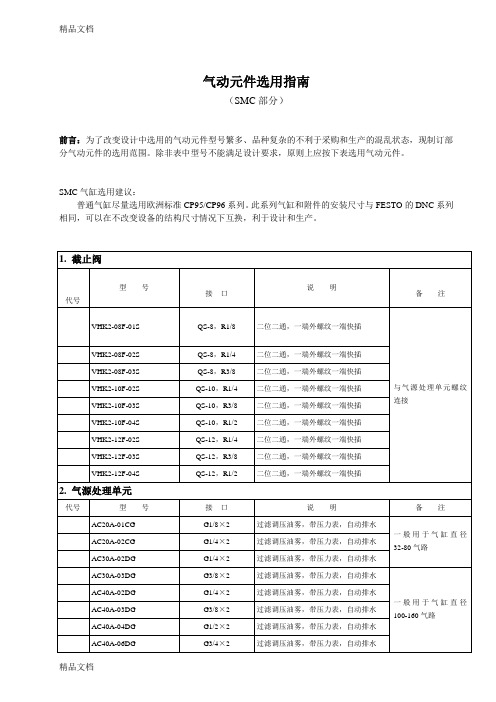
二位四通,侧面接管
VH400-03
G3/8×4
三位四通,中封式,侧面接管
VH401-03
G3/8×4
三位四通,中泄式,侧面接管
VH402-03
G3/8×4
二位四通,侧面接管
VH400-04
G1/2×4
三位四通,中封式,侧面接管
VH401-04
G1/2×4
三位四通,中泄式,侧面接管
VH402-04
G1/8×3
二位三通,直动,24VDC
VT307-5D-02
G1/4×3
二Hale Waihona Puke 三通,直动,24VDCVP342-5D-01A
G1/8×3
二位三通,内先导,常断式,24VDC
VP342-5D-02A
G1/4×3
二位三通,内先导,常断式,24VDC
VP542-5D-02A
G1/4×3
二位三通,内先导,常断式,24VDC
二位五通,内先导,双电控,24VDC
2.气源处理单元
代号
型号
接口
说明
备注
AC20A-01CG
G1/8×2
过滤调压油雾,带压力表,自动排水
一般用于气缸直径32-80气路
AC20A-02CG
G1/4×2
过滤调压油雾,带压力表,自动排水
AC30A-02DG
G1/4×2
过滤调压油雾,带压力表,自动排水
AC30A-03DG
G3/8×2
过滤调压油雾,带压力表,自动排水
1.截止阀
(1)价格低服饰□学习用品□食品□休闲娱乐□小饰品□代号
型号
(二)上海的人口环境对饰品消费的影响接口
说明
电磁阀规格表

ZCT-6ZA ZCT-6ZA 81127300.1230 91127300.14全佳
G1/2 DN15 PN0.025-1.6MPa 220V/AC 50Hz G1/2 DN14 PN0.025-1.6MPa 220V/AC 50Hz G1/2 DN6 PN0-0.4MPa 24V/DC
6 7 8 9 10
全佳 自力 自力
2231015BHT
G1/2 DN10 PN0.03-1.0MPa 220V/AC 50-60Hz AC380V AC220V G1/4 G1/4 DN6 DN6 0.6MPa 0.6MPa
宁波全佳气动元件制造有限公司 上海自力电磁阀厂 上海自力电磁阀厂 宁波全佳气动元件制造有限公司 宁波全佳气动元件制造有限公司 宁波全佳气动元件制造有限公司
油灶
11
KSQⅧ-A-4.5-20(电磁式)
备注
铁路蒸饭箱、船用开水 器、保温台均使用 铁路优选
船用优选
SMC VCW21-4D-5-02F(品牌:SMC) 全佳 欧凯 2231006HT OK6203A-B06-C2-G1/4-D110-304 ZCT-6
G1/2 DN6 PN0-0.6MPa 220V/AC 50-60Hz B06-C2-G1/4-D110-304 DN3 0~12bar 80℃ 0~10bar -5~150℃ 介质:蒸汽、水、油 DC110V
电磁阀规格表
序号 1 2 3 4 5 品牌 自力 ZCT-6ZCS 型号 AC220V AC220V G1/4 G1/4 DN6 DN5 规格 0.05MPa 0~0.3MPa 制造商 上海自力电磁阀厂 SMC(中国)有限公司 宁波全佳气动元件制造有限公司 上海欧凯电磁阀制造有限公司 G1/2 余姚市仪表四厂 KSQI-D-4.5-20(DF-20D-Z)(欧凯) KSQⅤ-A-4.5-20(DF-20D-H) KSQⅢ-A-4.5-20H(DF-20-H) KSQⅢ-A-4.5-20CH(DF-20C-H) KSQI-A-6-60H(DF-60-H) KSQI-D-6-60(DF-60-Z) DF-10B 、 30B 、 30G 、 60G 等船用电热开水 器、整体厨房蒸饭箱 船用保温台等 船用开水器等AC220V电路 使用产品/场所 KSQI-A-6-60(DF-60) KSQⅢ-A-4.5-20(DF-20) KSQⅢ-A-4.5-20A(DF-20A) KSQⅢ-A-4.5-20C(DF-20C) KSQⅢ-A-4.5-20D(DF-20D)
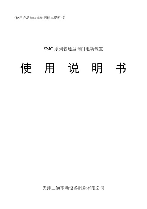
SMC系列产品使用说明书
5.4 SMC/HBC、SMC/JA部分回转产品的安装与拆卸方法是:
先将花键接头装到阀杆上,使电动装置二级减速机构的驱动轴位置与阀门所处位置相同。
(此时阀门在某一终端位置最理想)起吊电动装置,使其驱动轴与阀杆上的花键接头对准,同时应对准阀门与电动装置的连接螺孔。使驱动轴与花键接头配合装入,而后用螺栓将阀门与电动装置紧固可靠。
a、型号:该产品型号。
b、最大控制转矩:该产品出厂前调定的最大转矩值(N.m)。
c、输出转速:该产品在单位时间内输出轴的转圈数(r/min)。
d、最大转圈数:该产品位置指示机构指针从0~100%走满刻度情况下输出轴总的转圈数。
e、编号:该产品总序号或本年度产品的序号。
f、合同号:该产品年度订货合同号。根据它可查出产品出厂前的全部情况,便于售后服务。
与G·L·SW的触点信号不同,MDPI的阀位反馈信号是连续的。
(图19)所示为MDPI位置指示机构的结构。从图中可见其传动部分是若干对小模数配换齿轮,该机构对任何口径的阀门均能保证其指针做满刻度指示。
▼关于电动装置的控制器
对于一般控制原理,控制器是与电动装置分离的电气控制部件,它通常设置在控制室内为单独订货产品。
5.7电动装置的工作位置一般无原则要求。但推荐电动机轴线为水平状态,G·L·SW箱罩处于水平或垂直向上、向下状态,以利于产品的润滑、维修及阀位观测。
6.润滑
6.1产品出厂前已注入专用润滑脂,使用中每年应至少检查润滑情况一次,如无异常可继续使用。
6.2电动机轴承的润滑脂一般不必更换或添加。
6.3产品维修后更换润滑脂时应注意其抗氧化性、耐水性、耐热性、防锈性、机械稳定性等,并应注意其抗挤压性,以保证产品的润滑性能和较高的传动效率。
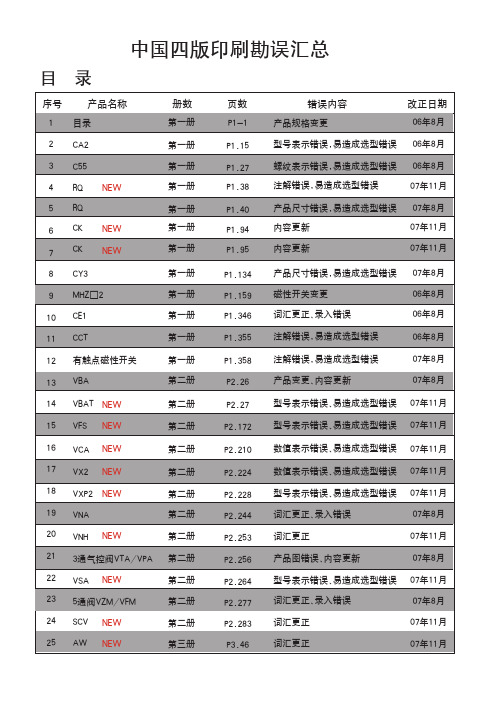
中文四版-SMC样本
20~40
CAT.C04-02A
20~40
CAT.C04-02A
40~100
CAT.C09-03A
32~125
CAT.C05-09B
32~100
CAT.C06-06A
125~300 8~25
CA3T2.C~05-2052B0
20~63 32~100
正确内容
32~100
CAT.C08-04B
12~100
07年8月 06年8月 06年8月 06年8月 06年8月 07年8月
说明:1.中国四版06年1月份正式印刷完成,06年8月份第一次增印,改动10页,07年8月份第二次增印,改动15页, 07年11月第三次增印,改动18页。
2.请注意将将更改信息通知相关客户,订货时予以确认。
执行元件
系列
气缸类型
缸径(mm) 中文样本编号 英文样本编号 日文样本编号 页号
页数 P3.55 P4.25 P4.26
错误内容 可换件型号错误 数值表示错误 型号表示错误、易造成选型错误
P4.34 P4.42
词汇更正、录入错误 型号表示不清、易造成选型错误
P4.64 P4.70
词汇更正、录入错误 追加系列
P4.102 型号表示内容错误
P4.110 型号表示内容错误
P5.09 数值表示错误
标准型气缸
图形符号
CA2系列 ( ~ )
1
1
。
弯
1系列
1
。
。 。
。
型号表示方法
mm
拉杆安装
除A54外 仅A54 BT-04 BT-06 BT-08
参见P.1.357。
正确内容
F
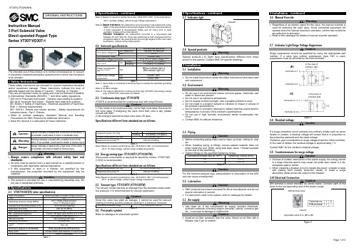
VT307N-TF2Z546EN 3端口弹簧式电磁阀说明书
AC
Inrush Holding
DIN terminal, grommet 100,200,110,220,240
24,12 Contact SMC -15 to 10% of rated voltage Note 1) 12.7 (50Hz), 10.7 (60Hz) 7.6 (50Hz), 5.4 (60Hz)
• Refer to product catalogue, Operation Manual and Handling Precautions for SMC Products for additional information.
• Keep this manual in a safe place for future reference.
ISO 4413: Hydraulic fluid power - General rules relating to systems. IEC 60204-1: Safety of machinery - Electrical equipment of machines. (Part 1: General requirements) ISO 10218-1: Robots and robotic devices - Safety requirements for industrial robots - Part 1: Robots.
Note 2)
Direct operated 2 position single solenoid Air
0 to 1 (High-pressure type), 0 to 0.7 (Standard type) -10 to 50 (No freezing) ≤20 (at 0.5 MPa) 10
SMC电磁阀样本
3.2
0.30 0.80
注) 2位单电控、4/2→5/3 (A/B→R1/R2)的值。
适合缸径 (mm)
~ø50
~ø80
插座引出方向
上方引出
可快速变更(F.P组件)
只要压一下手动按钮,插座的引出方向便可由上方变更成侧向。 由侧向变为上方的场合,不用手动操作按钮。
侧向引出
丰富的集中配线方式
S 组件 (串行传送)
F P T 组件 (D型辅助插座)
组件 (扁平电缆插座)
组件 (端子台盒)
L 组件 (导线引出)
M 组件 (多针插座)
EX5se0ri0es
25针
26针
保护构造
20针
可对应IP67
保护构造 可对应IP67
● 为了配线作业及维护容易,6种方式已标准化,4种方式的保护构造对应IP67。 ● 对S组件,有输入输出形式。(网关单元除外)
注3)英制尺寸为以下记号。
·N1: ø1/8"
·N3: ø5/32"
·N7: ø1/4"
·NM: 混合
上配管弯头为LN□、下配管弯头为BN□。
端板种类(仅对应EX600的S组件记入)
无记号 无端板 2 电源M12插头(最大供给电流 2A) 3 电源7/8英寸插头(最大供给电流 8A)
注)无SI单元的场合为无记号。
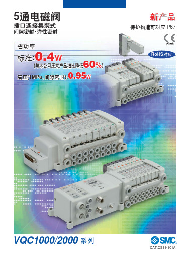
5通电磁阀
插口连接集装式
间隙密封·弹性密封
省功率
标准:0.4W
60 (与本公司原来产品相比降低
%)
0.95 高压(1MPa、间隙密封):
W
新产品
保护构造可对应IP67
[可选项]
RoHS对应
VQC1000/2000 系列
气动元件选用指南(SMC)

QS-12,R1/2
二位二通,一端外螺纹一端快插
2。气源处理单元
代号
型号
接口
说明
备注
AC20A-01CG
G1/8×2
过滤调压油雾,带压力表,自动排水
一般用于气缸直径32—80气路
AC20A-02CG
G1/4×2
过滤调压油雾,带压力表,自动排水
AC30A-02DG
G1/4×2
过滤调压油雾,带压力表,自动排水
VP542-5D-02A
G1/4×3
二位三通,内先导,常断式,24VDC
VP542—5D-03A
G3/8×3
二位三通,内先导,常断式,24VDC
VP742—5D-03A
G3/8×3
二位三通,内先导,常断式,24VDC
VP742—5D—04A
G1/2×3
二位三通,内先导,常断式,24VDC
VP342—5D—01B
G1/4×3
二位三通,直动,24VDC
VT307—5D—01
G1/8×3
二位三通,直动,24VDC
VT307—5D-02
G1/4×3
二位三通,直动,24VDC
VP342—5D-01A
G1/8×3
二位三通,内先导,常断式,24VDC
VP342—5D—02A
G1/4×3
二位三通,内先导,常断式,24VDC
VH600-10
G1×4
三位四通,中封式,侧面接管
4。脚踏阀
代号
型号
接口
说明
备注
VM230-02-40
G1/4×3
二位三通
5.电磁阀(气缸直径100以下优先选用VF系列)
SMC电动阀类产品说明书
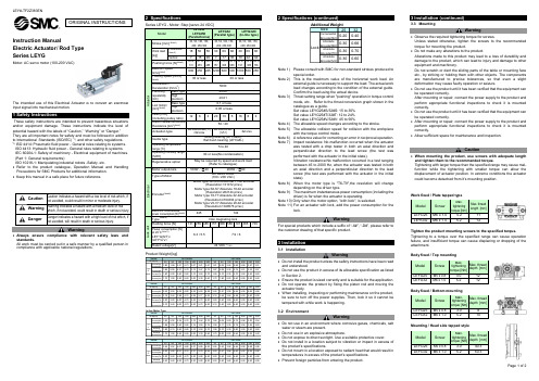
Instruction ManualElectric Actuator / Rod Type Series LEYGMotor: AC servo motor (100-200 VAC)The intended use of thisElectrical Actuator is to convert an electrical input signal into mechanical motion.1 Safety InstructionsThese safety instructions are intended to prevent hazardous situations and/or equipment damage. These instructions indicate the level of potential hazard with the labels of “Caution,” “Warning” or “Danger.” They are all important notes for safety and must be followed in addition to International Standards (ISO/IEC) *1), and other safety regulations. *1)ISO 4414: Pneumatic fluid power - General rules relating to systems. ISO 4413: Hydraulic fluid power - General rules relating to systems.IEC 60204-1: Safety of machinery - Electrical equipment of machines. (Part 1: General requirements)ISO 10218-1: Manipulating industrial robots -Safety. etc.∙ Refer to the product catalogue, Operation Manual and Handling Precautions for SMC Products for additional information. ∙ Keep this manual in a safe place for future reference.CautionCaution indicates a hazard with a low level of risk which, ifnot avoided, could result in minor or moderate injury.WarningWarning indicates a hazard with a medium level of riskwhich, if not avoided, could result in death or serious injury.DangerDanger indicates a hazard with a high level of risk which, ifnot avoided, will result in death or serious injury.Warning∙ Always ensure compliance with relevant safety laws and standards.All work must be carried out in a safe manner by a qualified person in compliance with applicable national regulations.2 SpecificationsSeries LEYG - Motor: Step [servo 24 VDC]Product Weight [kg]30501001502002503003050100150200250300Incremental E ncoder[S2] 1.80 1.99 2.31 2.73 3.07 3.41 3.67 1.81 2.02 2.26 2.69 2.95 3.27 3.51AbsoluteE ncoder[S6] 1.86 2.05 2.37 2.79 3.13 3.47 3.73 1.87 2.08 2.32 2.75 3.01 3.33 3.57AbsoluteE ncoder[T6] 1.80 2.00 2.40 2.80 3.10 3.50 3.70 1.90 2.10 2.30 2.70 3.00 3.30 3.60Absolute E ncoder[V6]1.701.902.202.603.003.303.601.701.902.202.602.903.203.4030501001502002503003050100150200250300Incremental E ncoder[S2] 3.24 3.50 4.05 4.80 5.35 5.83 6.28 3.24 3.51 3.90 4.64 5.06 5.56 5.96AbsoluteE ncoder[S6] 3.18 3.44 3.99 4.74 5.29 5.77 6.22 3.18 3.45 3.84 4.58 5.00 5.50 5.90AbsoluteE ncoder[T6] 3.20 3.40 4.00 4.70 5.30 5.70 6.20 3.20 3.40 3.80 4.60 5.00 5.50 5.90Absolute E ncoder[V6]3.103.404.004.705.305.706.203.103.403.804.505.005.505.90In-line Motor Type30501001502002503003050100150200250300IncrementalE ncoder[S2] 1.83 2.02 2.34 2.76 3.10 3.44 3.70 1.84 2.05 2.29 2.72 2.98 3.30 3.54AbsoluteE ncoder[S6] 1.89 2.08 2.40 2.82 3.16 3.50 3.76 1.90 2.11 2.35 2.78 3.04 3.36 3.60AbsoluteE ncoder[T6] 1.90 2.10 2.40 2.80 3.10 3.50 3.70 1.90 2.10 2.30 2.80 3.00 3.30 3.60Absolute E ncoder[V6]1.701.902.202.603.003.303.601.702.002.202.602.903.203.4030501001502002503003050100150200250300Incremental E ncoder[S2] 3.26 3.52 4.07 4.82 5.37 5.85 6.30 3.26 3.53 3.92 4.66 5.08 5.58 5.98AbsoluteE ncoder[S6] 3.20 3.46 4.01 4.76 5.31 5.79 6.24 3.20 3.47 3.86 4.60 5.02 5.52 5.92AbsoluteE ncoder[T6] 3.20 3.40 4.00 4.70 5.30 5.80 6.20 3.20 3.40 3.80 4.60 5.00 5.50 5.90Absolute E ncoder[V6]3.203.404.004.705.305.806.203.203.403.804.605.005.505.90Stroke[mm] TypeofMotorLEYG32M LEYG32L Stroke[mm] TypeofMotorSeriesSeriesLEYG25M LEYG25L LEYG25M LEYG25L Stroke[mm] SeriesLEYG32M LEYG32L Stroke[mm] TypeofMotorTypeofMotorSeries2 Specifications (continued)A dditional Weight2532Incremental E ncoder[S2]0.200.40Absolute E ncoder[S6]0.300.66Absolute E ncoder[T6]0.300.70Absolute E ncoder[V6]0.300.60Size LockNote 1) Please consult with SMC for non-standard strokes produced tospecial order.Note 2) This is the maximum value of the horizontal work load. Anexternal guide is necessary to support the load. The actual work load changes according to the condition of the external guide. Confirm the load using the actual device.Note 3) Thrust setting range when "pushing" operation in torque controlmode, etc. Refer to the thrust conversion graph shown in the catalogue as a guide.Set value LEYG25#S/32#S: 15 to 30% Set value LEYG25#T/32#T: 12 to 24% Set value LEYG25#V/32#V: 45 to 90%Note 4) The allowable speed changes according to the stroke.Note 5) The allowable collision speed for collision with the workpiecewith the torque control mode.Note 6) A reference value for correcting an error in reciprocal operation. Note 7) Impact resistance: No malfunction occurred when the actuatorwas tested with a drop tester in both an axial direction and perpendicular direction to the lead screw (the test was performed with the actuator in the initial state).Vibration resistance:No malfunction occurred in a test ranging between 45 to 2000 Hz, when the actuator was tested in both an axial direction and a perpendicular direction to the lead screw (the test was performed with the actuator in the initial state).Note 8) When the motor type is "T6-T9",the resolution will changedepending on the driver type.Note 9) The maximum instantaneous power consumption (including thedriver) is for when the actuator is operating.Note 10) Only when the motor option, "with lock", is selected.Note 11) For an actuator with lock, add the power consumption for thelock.WarningFor special products which include a suffix of “-X#”, “-D#”, please refer to the customer drawing of that specific product.3 Installation3.1 InstallationWarning∙ Do not install the product unless the safety instructions have been read and understood.∙ Do not use the product in excess of its allowable specification as listed in Section 2.∙ Ensure the product is sized correctly and is suitable for the application. ∙ Do not operate the product by fixing the piston rod and moving the actuator body.∙ When installing, inspecting or performing maintenance on the product, be sure to turn off the power supplies. Then, lock it so it cannot be tampered with while work is happening.3.2 EnvironmentWarning∙ Do not use in an environment where corrosive gases, chemicals, salt water or steam are present.∙ Do not use in an explosive atmosphere.∙ Do not expose to direct sunlight. Use a suitable protective cover.∙ Do not install in a location subject to vibration or impact in excess of the product’s specifications .∙ Do not mount in a location exposed to radiant heat that would result in temperatures in excess of the product’s specifications. ∙ Prevent foreign particles from entering the product.3 Installation (continued)3.3 MountingWarning∙ Observe the required tightening torque for screws.Unless stated otherwise, tighten the screws to the recommended torque for mounting the product.∙ Do not make any alterations to the product.Alterations made to this product may lead to a loss of durability and damage to the product, which can lead to injury and damage to other equipment and machinery.Do not scratch or dent the sliding parts of the table or mounting face etc., by striking or holding them with other objects. The components are manufactured to precise tolerances, so that even a slight deformation may cause faulty operation or seizure.∙ Do not use the product until it has been verified that the equipment can be operated correctly.After mounting or repair, connect the power supply to the product and perform appropriate functional inspections to check it is mounted correctly.∙ Do not use the product until it has been verified that the equipment can be operated correctly.∙ After mounting or repair, connect the power supply to the product and perform appropriate functional inspections to check it is mounted correctly.∙ Allow sufficient space for maintenance and inspection.Caution∙ When mounting the product, use screws with adequate length and tighten them to the recommended torque.Tightening with larger torque than the specified range may cause mal-function while the tightening with smaller torque can allow the displacement of actuator position. In extreme conditions the actuator could become detached from it’s mounting position.Work fixed / Plate tapped typeTighten the product mounting screws to the specified torque.Tightening to a torque over the specified range can cause operation failure, and insufficient torque can cause displacing or dropping of the attachment.Body fixed / Top mountingBody fixed / Bottom mounting Mounting / Head side tapped styleModel Screw Max.tighteningtorque [Nm]Max. thread depth [mm] LEYG25 M5 x 0.8 3.0 12LEYG32 M6 x 1.0 5.2 12 Model Screw Max.tighteningtorque [Nm]Max. thread depth [mm] LEYG25 M5 x 0.8 3.0 40.3LEYG32 M6 x 1.0 5.2 50.3ORIGINAL INSTRUCTIONSModelLEYG25 LEYG25D (Parallel/In-line )LEYG32 (Parallel type) LEYG32D (In-line type) A c t u a t o r Stroke [mm] Note1)30, 50, 100, 150, 200, 250,300 30, 50, 100, 150, 200, 250,300 30, 50, 100, 150,200, 250,300 Work load [kg] HorizontalNote 2)18 50 50 30 60 60 30 60 60 Vertical 7 15 29 7 17 35 10 22 44Pushing force [N] Note3)65 to 131 127 to 255 242 to 485 79 to 157 154 to 308 294 to 588 98 to 197 192 to 385 368 to 736Maximum Speed[mm/s]Note4)900 450 225 1200 600 300 1000 500 250 Pushing Speed [mm/s]Note5)35 or less 30 or less Acceleration / Deceleration [mm/s 2] 5000 Positioningrepeatability [mm] Basic type ±0.02 Highprecision ±0.01Lost motion [mm] Note6) Basic type 0.1 or lessHigh precision 0.05 or lessLead [mm](including pulley ratio)12 6 3 20 10 5 16 8 4 Impact resistance/vibrationResistance [m/s 2] Note7)50 / 20 Actuation type Ball screw and Belt [1:1] / Ball screw Ball screw and Belt[1.25:1] Ball screwGuide typeSliding bearing (LEYG#M), Ball bush bearing (LEYG#L) Operating temperature range [℃] 5 to 40 Operating humidity range [%RH] 90 or less(No condensation) Regenerative optionMay be required by speed and work load(Refer to catalogue)E l e c t r i c a l Motor output/size 100W /☐40 200W /☐60 Type of MotorAC servo motor (100 / 200 VAC) Encoder Note8) Motor type S2-S3:Incremntal 17-bit encoder(Resolution:131072 p/rev)Motor type S6-S7:Absolute 18-bit encoder (Resolution:262144 p/rev)Motor type T6-T7:Absolute 22-bit encoder(Resolution:4194304 p/rev) Motor type V6-V7:Absolute 20-bit encoder (Resolution:1048576 p/rev) Maximum instantaneous power consumption [W] Note9) 445 724 L o c k u n i tType Note10) Non magneting lock Holding force [N] 131 255 485 157 308 588 197 385 736 Power consumption [W] at 20 ℃ Note11) LEY*G(S/T)* /LEY*G V * 6.3 / 5.5 7.9 / 6 Rated voltage[V] 24 VDC 0-10% Model Screw Max.tighteningtorque [Nm]Max. thread depth [mm] LEYG25 M5 x 0.8 3.0 8 LEYG32 M6 x 1.0 5.2 10Model Screw Max.tighteningtorque [Nm] Max. thread length [mm]LEYG25 M6 x 1.05.2 11 LEYG32 M6 x 1.0 5.2 123 Installation (continued)3.4 LubricationCaution∙SMC products have been lubricated for life at manufacture, and do notrequire lubrication in service.∙If a lubricant is used in the system, refer to catalogue for details.∙The recommended grease is lithium grade No.2Applied Region Grease Pack Number Weight [g]Piston rodGuideGR-S-010 10GR-S-020 20∙For products which include a “25A-” prefix the recommended grease islow condensation grease.Applied Region Grease Pack Number Weight [g]Piston rodGuideGR-D-010 104 Wiring4.1 WiringWarning∙Adjustment, mounting or wiring changes should not be carried outbefore disconnecting the power supply to the product.Electric shock, malfunction and damage can result.∙Do not disassemble the cables.∙Use only specified cables.Use only specified cables otherwise there may be risk of fire anddamage.∙Do not connect or disconnect the wires, cables and connectors whenthe power is turned on.Caution∙Wire the connector correctly and securely.Check the connector for polarity and do not apply any voltage to theterminals other than those specified in the Operation Manual.∙Take appropriate measures against noise.Noise in a signal line may cause malfunction. As a countermeasureseparate the high voltage and low voltage cables, and shorten thewiring lengths, etc.∙Do not route input/output wires and cables together with power or highvoltage cables.The product can malfunction due to noise interference and surgevoltage from power and high voltage cables close to the signal line.Route the wires of the product separately from power or high voltagecables.∙Take care that actuator movement does not catch cables.∙Operate with all wires and cables secured.∙Avoid bending cables at sharp angles where they enter the product.∙Avoid twisting, folding, rotating or applying an external force to thecable.Risk of electric shock, wire breakage, contact failure and loss of controlof the product can result.∙Select “Robotic cables”in applications where cables are movingrepeatedly (encoder/ motor/ lock).Refer to the relevant operation manual for the bending life of the cable.∙Confirm correct insulation.Poor insulation of wires, cables, connectors, terminals etc. can causeinterference with other circuits. Also there is the possibility thatexcessive voltage or current may be applied to the product causingdamage.∙R efer to the auto switch references in “Best Pneumatics“ when an autoswitch is to be used4.2 Actuator Ground connectionCaution∙The Actuator must be connected to ground to shield the actuator fromelectrical noise. The screw and cable with crimping terminal andtoothed washer should be prepared separately by the user.4 Wiring (continued)4.3 Wiring of Actuator to ControllerAC servo motor driverWarningUse only specified cables otherwise there may be risk of fire and damage5 How to Order∙For standard products, refer to the catalogue on the SMC website(URL: https://) for the how to order information.6 Outline Dimensions∙For standard products, refer to the catalogue on the SMC website(URL: https://) for outline dimensions.7 Maintenance7.1 General MaintenanceCaution∙Not following proper maintenance procedures could cause the productto malfunction and lead to equipment damage.∙If handled improperly electricity and compressed air can be dangerous.∙Maintenance of electromechanical and pneumatic systems should beperformed only by qualified personnel.∙Before performing maintenance, turn off the power supply and be sureto cut off the supply pressure. Confirm that the power has beendischarged and the air is released to atmosphere.∙After installation and maintenance, apply operating pressure andpower to the equipment and perform appropriate functional andleakage tests to make sure the equipment is installed correctly.∙If any electrical or pneumatic connections are disturbed duringmaintenance, ensure they are reconnected correctly and safety checksare carried out as required to ensure continued compliance withapplicable national regulations.∙Do not make any modification to the product.∙Do not disassemble the product, unless required by installation ormaintenance instructions.∙Incorrect handling can cause an injury, damage or malfunction of theequipment and machinery, so ensure that the procedure for the task isfollowed.∙Always allow sufficient space around the product to complete anymaintenance and inspection.7 Maintenance (continued)7.2 Periodical Maintenance∙Maintenance should be performed according to the table below:AppearanceCheckBelt CheckInspection before daily operation ✓Inspection every six months* ✓✓Inspection every 1,000 km* ✓✓Inspection every 5 million cycles* ✓✓*whichever of these occurs first.∙Following any maintenance, always perform a system check. Do notuse the product if any error occurs, as safety cannot be assured ifcaused by any un-intentional malfunction.7.3 Appearance Check∙The following items should be visually monitored to ensure that theactuator remains in good condition and there are no concerns flagged;・Loose Screws,・Abnormal level of dust or dirt,・Visual flaws / faults,・Cable connections,・Abnormal noises or vibrations.7.4 Belt Check∙If one of the 6 conditions below are seen, do not continue operatingthe actuator, contact SMC immediately.・Tooth shaped canvas is worn out.Canvas fibre becomes “fuzzy”, rubber is removed, and the fibre gainsa white colour. The lines of fibre become very unclear.・Peeling off or wearing of the side of the belt.The corner of the belt becomes round and frayed, with threadsbeginning to stick out.・Belt is partially cut.Belt is partially cut. Foreign matter could be caught in the teeth andcause flaws.・Vertical line of belt teeth.Flaw which is made when the belt runs on the flange.・Rubber back of the belt is softened and sticky.・Crack on the back of the belt.8 Limitations of Use8.1 Limited warranty and disclaimer/compliance requirements∙Refer to Handling Precautions for SMC Products.9 Product disposalThis product should not be disposed of as municipal waste. Check yourlocal regulations and guidelines to dispose of this product correctly, inorder to reduce the impact on human health and the environment.10 ContactsRefer to or www.smc.eu for your local distributor /importer.URL : http// (Global) http// (Europe)'SMC Corporation, 4-14-1, Sotokanda, Chiyoda-ku, Tokyo 101-0021, JapanSpecifications are subject to change without prior notice from the manufacturer.© 2021 SMC Corporation All Rights Reserved.Template DKP50047-F-085M24VDC(5) Lock cable(4) Encoder cable(3) Motor cable(1) Electric Actuator(2) DriverHostcontroller,etc(6) I/O Connector。
SMC中文四版电子样本第一册(执行元件)2of6
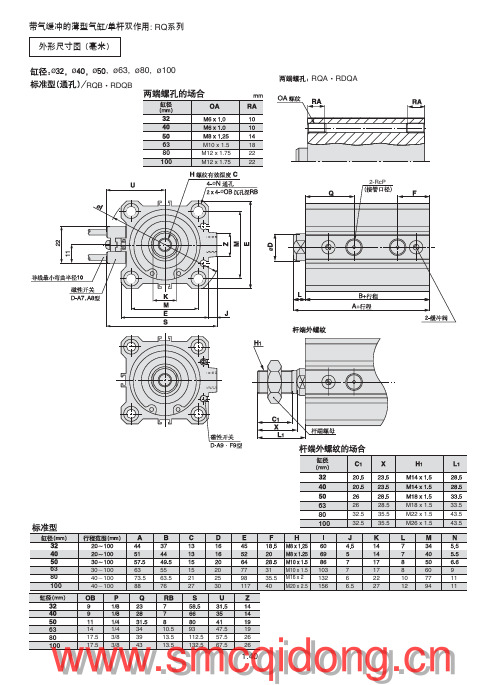
杆侧 气缸通口TP
⑦
⑧
⑥
R□LQB 缸径 -B□ 后退方向锁,右侧配管(虚线为左侧配管) . . = = .TH .TH ⑤ ① ④ ② ③
= .Max. T1
杆侧 气缸通口TP
无杆侧 气缸通口TP
⑥ ⑧ ⑦
= .Max. T2
= .T3
.
.
.
带旁通管路气缸的构成
序号 1 2 3 4 5 6 7 8 名 称 带锁带气缓冲的薄型气缸 PT弯头 节流阀 PT三通 金属体速度控制阀 弯头 旁通管 防火花罩 数量 1 1 1 1 2 2 1 2 型号
47.5 57.5 67.5
19 26 26
!"#$ !"=E
%/ F
!": RQ
安装件型号 CQ-L032
RQL·RDQL
63 80 100
CQ-L040 CQ-L050 CQ-L063 CQ-L080 CQ-L100 30~100 40~100 40~100 81.2 95 111 55 63.5 76 29 33.5 42 18 20 22 43.5 53.5 53.5 11 13 13
旁通配管 无记号 无
R
带旁通配管右配管 (防止落下)
L 带旁通配管左配管 (防止落下)
(
外形尺寸图 (毫米) ¿32(非常停止)
两端螺孔/R□LQA32
PL锁开放通口 加压状态下锁开放 55 22.5 9
锁方向 F 前进方向锁 B 后退方向锁
非 常 停 止
*配管的左右,是从杆侧观察。
*1台气缸应订购2只脚座。 *脚座型、法兰型附本体安装螺钉。 *双耳环型附耳环用销轴,弹性挡圈, 本体安装螺钉及垫圈。
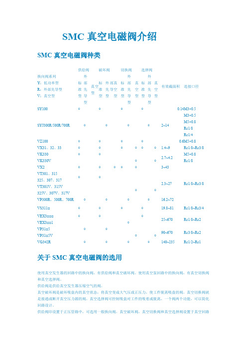
SMC真空电磁阀介绍
或存在有真空状态的回路中,故必须选用能在真空压力条件下工作的换向阀。真空换向阀要求不泄露,且
不用油雾润滑。故使用座阀式和膜片式阀芯结构比较理想。通径大时可使用外部先导式电磁阀。不给油润
滑的软质密封滑阀,由于其通用性强,也常作为真空用换向阀使用。
SMC 真空电磁阀的选用; 真空选择阀可控制吸盘对工件的吸着或脱离,一个 阀两个功能,可以简化回路设计。 供给阀印设置于正压管路中,可选用一般换向阀。 真空破坏阀,真空切换阀和真空选择阀设置于真空回路或存在有真空状态的回路 中 ,故必须选用能在真空压力条件下工作的换向阀。 真空换向阀要求不泄露,且不用油雾润滑。 故使用座阀式和膜片式阀芯结构比较理想。通径大时可使用外部先导式电磁阀。 不给油润滑的软质密封滑阀,由于其通用性强,也常作为真空用换向阀使用。. 使用真空发生器的回路中的换向阀,有供给阀和真空破坏阀。 使用真空泵回路中的换向阀,有真空切换阀和真空选择阀。 供给阀是供给真空发生器压缩空气的阀。 真空破坏阀是破坏吸盘内的真空状态,将真空变成大气压或正压力,使工件脱离 吸盘的阀。 真空切换阀就是接通或断开真空压力源的阀。
关于 SMC 真空电磁阀的选用
使用真空发生器的回路中的换向阀,有供给阀和真空破坏阀。使用真空泵回路中的换向阀,有真空切换阀 和真空选择阀。 供给阀是供给真空发生器压缩空气的阀。 真空破坏阀是破坏吸盘内的真空状态,将真空变成大气压或正压力,使工件脱离吸盘的阀。真空切换阀就 是接通或断开真空压力源的阀。真空选择阀可控制吸盘对工件的吸着或脱离,一个阀两个功能,可以简化 回路设计。 供给阀印设置于正压管路中,可选用一般换向阀。真空破坏阀,真空切换阀和真空选择阀设置于真空回路
○ ○
○
○
○○
○
○
○
施耐德电气 埃里VT电动分区阀配备AG AH执行器 规格表说明书

| 1Specification SheetErie VT Motorized Zone Valvewith AG/AH Actuators SpecificationsValveMediaHot and chilled waterMedia temperature range 0° to 93°C|Max. Glycol concentration 50%Pressure class PN20 (300 psi)Seat Leakage 0.01% (EN60534-4/ANSI class IV)∆Pm100 kPaGeneral Construction MaterialsBody Brass Stem Nickel-plated brass Seat Brass Paddle/stem o-rings Buna-N/EPDMActuatorSupply voltage 24 Vac @ 50/60 Hz230 Vac @ 50 HzPower consumption 6.5 W, 7.5 VAEnd switch 24-240 Vac (101/mA min. to 5 A)9-30 Vdc (100 mA max.)ControlOn/Off, 2 position, spring returnFull running time 30 sec (50 Hz)9 sec (S.R. function)Enclosure IP31General Construction Materials Base plate Stainless Steel Cover AluminiumProduct DescriptionSchneider Electric’s industry leading Erie Zone valve andactuators are suitable for the control of hot and chilled water in terminal unit applications.The VT valve’s high flow capacity paddle design provides a low pressure drop fluid control. The AG/AH actuator’s unique ‘pop-top’ connection allows for a quick and simple installation. The AG (General Close Off) and AH (High Close Off) are spring return actuators designed for two position control. Both spring return open and spring return closed functions are available. All Normally Closed actuators feature a manual override lever.EnvironmentShipping and storage -40 to 71°CMedia 0° to 93°C at 40°C ambient temp Humidity5 to 95% RH, non-condensingWeightsValve bodies 1/2”365 g 3/4” (all 2 way , 3 way Kvs 2.6 and 3.4) 410 g 3/4” (3 way Kvs 4.3 and 6.3) 500 g 1”590 g ActuatorAG/AH without end switch 500 g AG/AH with end switch545 gStandards/DirectivesElectroMagnetic Compatability [EMC] 2014/30/EU Low voltage directive [LVD]2014/35/EU Restriction of Hazardous Substances [RoHS2] 2011/65/EC Heat IEC 60068-2-2 Humidity IEC 60068-2-3 Cold IEC 60068-2-1 VibrationIEC 60068-2-6RecomendationsIt is recommended to fit a strainer upstream of the valve to increase reliability and to follow water treatment guidelines as detailed in VDI 2035.It is the responsibility of the installer or product specifier to verify media compatibility of the valves construction materials with the supplier of water treatment/heat transfer solution. Valves should be installed in the return pipe to reduce exposure to media temperature extremes.Available Part Numbers ValvesPart Number Thread KvsMax. ∆Pc (kPa)AG Actuator AH Actuator2-Way Threaded Valve BodiesVT22311/2 Rp 0.85410515VT2232 2.2275340 VT22333170205VT23323/4 Rp 2.2275340VT23333170205 VT2335 4.3135170 VT2337 6.5115135 VT2437 1 Rp 6.9115135 3-Way Threaded Valve BodiesVT32311/2 Rp 1.3410515VT3232 2.6275340 VT3233 3.5170205VT33323/4 Rp 2.6275340VT3333 3.5170205 VT3335 4.3135170 VT3337 6.5115135 VT3437 1 Rp 6.9115135ActuatorsPart Number VoltageEndSwitchControlSpring ReturnValve FunctionCableGeneral Close Off ActuatorsAG13A23024 Vac-Two position Normally Closed910 mm (36”)AG13A23A yes910 mm (36”)AG13U230230 Vac -910 mm (36”)AG13U23A yes910 mm (36”)AG23A23024 Vac-Normally Open 910 mm (36”)AG23A23A yes910 mm (36”)AG23U230230 Vac -910 mm (36”)AG23U23A yes910 mm (36”) High Close Off ActuatorsAH13A23024 Vac-Two position Normally Closed 910 mm (36”)AH13U230230 Vac -910 mm (36”)AH13U23A yes910 mm (36”)MountingThe Erie motorized zone valve may be mounted in horizontalor vertical piping configurations. When installed in horizontal piping, the actuator must be above the valve body. The actuator can be tilted left or right, but it must not be tilted below 85° from vertical.Installation ConsiderationsInstall the valve so that the paddle closes against the direction of flow. Flow is from A to B.When installing the actuator to a normally closed valve, place the actuator in the manually open position using the manual operating lever. The first time the valve is operated electrically, the manual operating lever of the actuator transfers to the automatic position.Use the manual operating lever to flush the system after installation. The vaves are designed for application in closed hydronic heating and cooling systems.High levels of dissolved oxygen and chlorine found in open systems may attack the valve materials and result in premature failure. Install over a drip pan if condensation in chilled water applications occurs.Installation Checks• Make sure the valve stem rotates freely before and after installing the actuator.• If the stem does not operate freely it may indicate that the stem was damaged and may require replacement of thevalve.• After the piping is under pressure, check the valve body and the connections for leaks.• After the valve and actuator are installed, power the actuator and check the operation.Note:• Do not use in systems that have substantial make-up water (open systems). Follow proper water treatment practicesand system procedures.• Three-way valves always require a normally closed actuator.• Three-way valves are always closed at the B port when no power is applied to the motor.• On power-up, the valve closes to A port on three-way valves.• Orientate the three-way valve body as needed for normally open or normally closed flow through the coil.Installing the Actuator Onto a Valve BodySlowly latch the manual operating lever in the open, engaged position (AG1 or AH1 only). Depress the release button. Align the body with the actuator to ensure the stem is inserted into the large mating hole on the bottom side of the actuator. Engage the actuator on the body and release the button.ReleaseHoleManualNote: Do not use the valve body to manually open the actuator as damage to the valve actuator will result.Theory of OperationThe Erie Pop T op actuators are two-position valve series with spring return actuators. When powered, the actuator movesto the desired end stop position, tensing the spring return system. When power is removed the actuator returns to the normal rest position. The Erie AG/AH Pop T op series actuators can be purchased with a built in auxiliary SPDT end switchfor interfacing or signaling the end stop valve position to other equipment.MaintenancePopTfree. Replace defective modules. Actuator may be replaced without removing the valve.Regular maintenance of thetotal system is recomended to assure sustained, optimum performance.2-Way Valve with Normally Closed ActuatorNormally Open Actuator3-Way Valve in Mixing Configuration,Normally Open to the Coil3-Way Valve in Mixing Configuration,Normally Closed to the Coil3-Way Valve in Diverting Configuration,Normally Closed to the Coil3-Way Valve in Diverting Configuration,Normally Open to the CoilApplication ExamplesNote:Three-way N.O. applications can be achieved when using a N.C. actuator , by piping the valve in reverse. The three-way examples above show normally closed actuators.Threaded ConnectionsApply Teflon tape to all but the last two threads of male pipe thread. Hand screw the pipe into the valve, turning it as far as it will go. Use a wrench to fully tighten the valve to the pipe. Do not over tighten or strip the threads.Dimensions (mm)VT/AG AssemblyVT/AH Assembly6|Specification Sheet。
