Fluke 810_快速参考指南中文版(振动测试仪)
fluke中文使用手册805
May 2012 (Simplified Chinese)© 2012 Fluke Corporation. All rights reserved. Specifications are subject to change without notice. All product names are trademarks of their respective companies.805 Vibration Meter用户手册有限担保及责任范围Fluke 公司保证其每一个Fluke的产品在正常使用及维护情形下,其用料和做工都是毫无瑕疵的。
保证期限是一年并从产品寄运日起开始计算。
零件、产品修理及服务的保证期是 90天。
本保证只提供给从 Fluke授权经销商处购买的原购买者或最终用户,且不包括保险丝、电池以及因误用、改变、疏忽、或非正常情况下的使用或搬运而损坏(根据 Fluke的意见而定)的产品。
Fluke 保证在 90天之内,软件会根据其功能指标运行,同时软件已经正确地被记录在没有损坏的媒介上。
Fluke 不能保证其软件没有错误或者在运行时不会中断。
Fluke 仅授权经销商将本保证提供给购买新的、未曾使用过的产品的最终用户。
经销商无权以 Fluke的名义来给予其它任何担保。
保修服务仅限于从 Fluke授权销售处所购买的产品,或购买者已付出适当的Fluke国际价格。
在某一国家购买而需要在另一国家维修的产品,Fluke 保留向购买者征收维修/更换零件进口费用的权利。
Fluke 的保证是有限的,在保用期间退回 Fluke授权服务中心的损坏产品,Fluke有权决定采用退款、免费维修或把产品更换的方式处理。
欲取得保证服务,请和您附近的Fluke服务中心联系,或把产品寄到最靠近您的Fluke服务中心(请说明故障所在,预付邮资和保险费用,并以 FOB目的地方式寄送)。
Fluke 不负责产品在运输上的损坏。
FTB-810快速使用指南

FTB-810快速人门作者:江怀目录:∙仪表结构---------------------------------------------------------------------1-3 1.FTB-1-810结构介绍----------------------------------------------12.FTB-1平台结构及按键功能介绍-----------------------------1-2 3.FTB-810结构介绍-------------------------------------------------3∙仪表配置与测试-----------------------------------------------------------3-14 1.仪表启动与测试配置--------------------------------------------3-7 2.测试执行与结果--------------------------------------------------8-93.生成测试报告-----------------------------------------------------10-11 4.快速测试------------------------------------------------------------11-12 5.误码/告警----------------------------------------------------------12-13 6.RDT/复用段/指针/开销等功能测试------------------------13-14∙远程控制--------------------------------------------------------------------15 1.Telnet远程登陆--------------------------------------------------152.VNC远程控制-----------------------------------------------------15∙选件激活--------------------------------------------------------------------15-16∙软件升级,安装与激活------------------------------------------------16-17∙产品维护须知-------------------------------------------------------------17-18仪表结构:FTB-1/810仪表由FTB-1平台和FTB-810模块两部分组成,平台主要是提供基于不同应用模块的公共功能部分,模块则提供具体的测试功能。
新型 Fluke 810 振动测试仪

Fluke 810 振动测试仪型 Fluke 810 振动测试仪:满足您的当前需要... 使用全新的振动测试方法来控制未经计划的停产,防止问题反复发生,设置修优先级,并对资源进行管理。
新型 Fluke 810 振动测试仪是一种非常先进的故障排查工具,可供现在需要一种适宜解决方的机械维修人员使用。
该振动测试仪采用独特的诊断技术,可帮助您快速发现机械问题并确定优先级,从而成为一种方便的振动析工具。
您以您的公司、团队或工作而自豪。
您会做出各种努力来使一切正常运转,但有时却没有足够的时间与资源来应付手的工作,更不用说主动采取机械维护措施了。
Fluke 810 振动分析仪可将您向前推进一步,它可在您进行首批测量时,通过一简便的逐步过程来报告机器故障,而不需要以前的测量历史记录。
诊断、严重性以及维修建议相结合,有助于您做出有针对性的护决定,并首先解决关键问题。
可在某些经销商处购得可通过测试仪来识别和找到最常见的机械故障(轴承、未对准、不平衡、松动),并将维护工作重点集中于查找根本原因,从而减少未经计划的停产具有四个级别的故障严重性标尺有助于排列维护工作的优先顺序维修建议可帮助技术人员采取纠正措施测试仪上的关联帮助可为新用户提供实时提示和指南2 GB 可扩展仪器存储器为用户的机器数据提供了足够空间自检功能可确保最优性能和更长的工作时间通过激光转速计可获得精确的机器运转速度,可充满信心地进行诊断三轴加速度计将单个轴加速度计的测量时间缩短 2/3Viewer PC 软件扩展了数据存储和跟踪容量 对有问题的设备进行故障排查,并了解故障的根本原因在计划维护之前和之后对设备进行调查,并确认维修效果对新设备进行调试,并确保正确安装提供可量化的设备状况证明,并推动在维修或更换方面进行投资对维修活动进行计划和排列优先顺序,并更加高效地运行对设备故障进行预期,并对备件库存进行控制对新的或缺乏经验的技术人员进行培训,并在整个团队中建立信心和技能。
福禄克805振动烈度(点检)仪产品设计荣获2013年度IDEA杰出工业设计奖
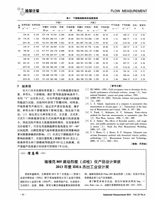
3 结束 语
在大 口径水 流量标 准装 置 上 ,针 对 换 能器 安装 位
[ 参考文献 ]
l 1 I I E C 6 0 0 4 1 —1 9 9 1 : F i e l d a c c e p t a n c e t e s t s t o d e t e r m i n e t h e h y —
s i t . t i me l f o wme t e s r mo d e l e d w i t h t h e o r e t i c a 1 v e l o c i t y p r o i f l e s :
m e t h o d o l o g y[ J ] .M e a s u r e me n t S c i e n c e a n d T e c h n o l o y, g
论 :( 1 ) 相 比其 它 几种 安装 方 式 ,方 式 Ⅲ、方式 Ⅳ 、
方式 V三 种 换 能 器 安 装 方 式 的 超 声 流 量 计 的误 差 最 小 ,因此 实际 开展水 大流 量现 场 校准 时 ,在 安装 条 件
I 2 l A S M E P T C 1 8 —2 0 0 2 . H y d r a u l i c t u r b i n e s a n d p u m p . t u r b i n e s j S I ,1 9 8 7 .
2 0 0 o,1 2( 1 1 ):1 8 0 2—1 8 1 1 .
距 离单 弯头 和下 游 蝶 阀等 阻流 件 8 D 以上 的距 离 ,双
声道 超声 波流量 计 的误差 可控制 在 1 % 以内 。
[ 编辑 :邓茂焕 ]
斑马技术公司DS8108数字扫描仪产品参考指南说明书
Fluke 810 振动测试仪用户指南说明书

810SC-20.810SC-2054Check price and availability at /wtbsoftware and resources For more information, go to /vibrationVibration get answers now!The Fluke 810 Vibration Tester is the most advanced troubleshooting tool for mechanical maintenance teams who need an answer now. It is a unique new kind of troubleshooting tool, engineered to detect and evaluate the most common mechanical problems.The Fluke 810 Vibration Tester uses a simple step-by-step process to report on machine faults the first time measure-ments are taken, without prior machinehistory.Fluke 810 Vibration Tester Take a vibration expert alongsimple 3 step process The Fluke 810 helps you locate and diagnose common mechanical problems and prioritize repair actions in three simple steps:Viewer PC software • Store and track your data • Generate diagnostic reports and track the severity of your machine’s condition • Import and store JPEG and Fluke IS2 thermal imagesBreakthrough diagnostic technology The Fluke 810’s diagnostic technology combines powerful algorithms with a database of real-world measurement experience, making the Fluke 810 the most advanced troubleshooting tool for mechanical maintenance teams.analyze most common equipment:• Motors • Fans and blowers • Belt and chain drives • Gearboxes • Pumps • Compressors • SpindlesDetect the most common causes of mechanical failure:• Bearing problems • Misalignment • Unbalance • Looseness Specificationsordering informationInteractive, self-paced training on DVD Learn more about the basics of vibration and how to fully utilize the features and functionality of the Fluke 810. Fluke has partnered with Mobius Institute, an industry leader in vibration training, to develop an interactive training DVD included with each Fluke 810.use the Fluke 810 to:• Easily determine the root cause, location and severity of common mechanical faults • Efficiently prioritize and plan equipment repair or replacement • Effectively deploy maintenance resources at the point of greatest impact 1. setup: Vibration testing has never been easier The Fluke 810 asks for basic machine informa-tion you already know, like RPM and horse-power. Its onboard Info feature gives you field tips for setting up and taking measurements like a pro. 2. Measure: The Fluke 810 easily fits into your maintenance routine. Use it to quickly troubleshoot problems or monitor machine condition. 3. Diagnose: Fix it right the first time with the press of a button, the Fluke 810 identifies the root cause, its location, and the problem’s severity.810SC-20.810SC-20。
振动测试仪在电机故障诊断中的应用

振动测试仪在电机故障诊断中的应用孟宪宽;周晓东;李超;陈伟林【摘要】以瀑布沟发电站电机故障为例,介绍了水电站电机故障对机组及系统带来的危害,分析了电机的常见故障及常规检测方法,重点介绍了振动测试仪对瀑布沟电站电机故障的诊断分析,根据分析结果提出了有效的解决方案,为电厂的安全稳定运行提供了保障.【期刊名称】《水电与新能源》【年(卷),期】2016(000)011【总页数】3页(P56-58)【关键词】电机故障;振动测试仪;诊断分析【作者】孟宪宽;周晓东;李超;陈伟林【作者单位】国电大渡河流域水电开发有限公司,四川成都 610047;国电大渡河检修安装有限公司,四川乐山 614900;国电大渡河检修安装有限公司,四川乐山614900;国电大渡河检修安装有限公司,四川乐山 614900【正文语种】中文【中图分类】TM307+.1;TP206+.3瀑布沟水电站机组技术供水泵电机自2009年投运以来,已经运行6 a多,技术供水泵电机相继出现了匝间短路、异响等现象,直接影响到机组的安全正常运行。
在2015-2016年检修期中,相继对6台机组共计12台电机进行了全面的检查,对电机故障进行了诊断分析,查找出各种故障现象,并对电机进行了相应的修复处理。
目前,这12台重庆赛力盟电机运行正常,有力地保证了机组的可靠安全运行。
1)机组辅助电机对机组的正常运行起着至关重要的作用,以机组技术供水泵电机为例,作为机组运行时的重要保障,一旦出现供水中断,将会引起机组的非计划停机,对电网系统产生影响,对用电企业造成损失。
2)如果电机一直处理异常状态,会缩短设备正常的使用寿命。
3)电机带“病”运行,对设备及人身均存在一定的危险因素。
4)电机的不正常运行状态,将会造成维护费用大量上升。
一般电机故障都是集电气与机械于一体的,在征兆的表现呈现多样性,既有机械故障的一般特性,也有电气、磁场等故障特性[1]。
通过对这些电机故障的跟踪分析,发现电机故障大部分源于机械故障(主要是轴承故障),其表征现象也比较明显,即电机运行时出现明显的异响;少部分为电气故障(主要是绕组故障),在上述12台电机中,仅2台为电气故障。
Fluke 810_Viewer Software 安装指南中文版(振动测试仪)

Viewer Software安装指南November 2010 (Simplified Chinese)© 2010 Fluke Corporation. All rights reserved. Specifications are subject to change without notice.All product names are trademarks of their respective companies.目录标题页码概述 (1)如何和 Fluke 联系 (1)硬件要求 (2)操作系统软件要求 (2)Windows XP 系统要求 (3)Windows 7 和 Vista 系统要求 (3)系统软件安装 (4)Windows Installer 3.1 (4).NET Framework (5)Windows Mobile Device Center (7)SQL Server (8)SQL Server Compact 3.5 SP1 (15)SQL Server Compact for Devices (16)ActiveSync (16)Viewer Software 安装 (17)810 Vibration Tester 安装 (25)如何排除软件安装故障 (26)安装之后,Viewer Software 程序无法打开 (26)在 SQL Server 2005 Express Edition 安装过程中,SQL Server出现故障 (27)弹出消息显示错误 2147749896 (29)弹出消息显示 "SQL Server Setup Failed to Execute a Command forServer Configuration" (30)SQL Server 2005 Express Edition 无法安装 (30)810 Tester 未与 Viewer Software 相连接 (30)Windows Installer 3.1 未安装 (31)"Auto Run Viewer Software Device Detection"(Windows 启动)无法正常工作 (32)在 ActiveSync 的安装过程中弹出显示,要求提供可移动磁盘 (32)数据库备份文件夹是空的 (34)如何识别系统是 32 位,还是 64 位 (36)如何手动备份 Viewer Software 数据 (37)如何在 Windows 7 和 Vista 中以管理员身份自动运行任意应用程序 (37)出现 Mobile Device Center 安装屏幕 (40)使用 Mobile Device Center,810 Vibration Tester 未连接到 ViewerSoftware。
振动频谱分析基础

Fluke 810振动诊断仪——旋转机器振动基础知识——旋转机器振动测试提供关键的机器状态信息。
我们来了解一些关于振动的基础知识:y电机轴以1776 RPM的转速带动泵轴y轴上的一个重点在所有径向产生一个向外的力y传感器每转检测到一次振动y正弦波表示轴旋转时的振动y轴完整旋转一周产生一个周期的正弦波——当重点处于顶部时形成波峰,重点处于底部时形成波谷周/分钟1776 转/分钟 = 1776(转轴) (正弦波)波形分析基础——术语循环不断重复- 一个完整的正弦波为一个循环 -- 一个循环每分钟= 1 CPM - 一个循环每秒= 1 CPS (赫兹)峰值峰-峰值-RMS = 0.707 峰值-峰-峰值 = 2 峰值位移为移动的距离 d mils p-p速率为距离与时间之比V = d / t in/sec peak加速度为速率与时间之比 A = V / t in/sec2 (G) rmsFluke 810振动诊断仪——旋转机器机器部件y该泵有10个轮叶y轴每旋转一周,传感器检测到10次叶片振动y正弦波显示10次完整的循环,形成幅度较小的轴正弦波y振动水平较小意味着幅度低于轴振动y由于主轴的质量大,将导致振动强于叶轮10 次振动每转= 10 个循环每转(转轴) (正弦波)复合波形如果我们将两个正弦波(轴和泵轮)叠加在一起,将形成以下波形:- 1 次轴转动- 10 次泵轮振动但实际上振动彼此叠加,更像以下波形:真实旋转机器的20次或30次振动可能是如下波形:Fluke 810振动诊断仪——旋转机器频率(谱)分析y 波形含有关于被测机器的信息 y 但不同事件的模式相互叠加,杂乱无序——太复杂FFTy 采用快速傅里叶变换(FFT)方法,可将采集的波形从时域(幅值与时间关系)转换至频域(幅值与频率关系)。
幅值幅值y 由于特定的振动幅值可与机器的运行速度紧密相关,所以频谱简化了数据的理解。
事件 频率 • 由测试仪执行变换,简化波形 • 频谱是信号幅值(y 轴)与频率(x 轴)的关系曲线 • 这些尖峰处于特定的频率,表示机器正在发生的现象。
F810振动测试仪简介

©02010 Fluke Corporation
810振动测试仪简介
23
Fluke 810与客户日常维护
使用Fluke 810振动测试仪可以: • 进行故障排查,找出问题的根本原因 • 对维修效果进行确认 • 调试新的设备 • 安装之后对设备进行检查 • 提供可量化的证明 • 做出正确决策 – 维修还是更换? • 对维修活动排列优先级和进行计划 • 预期设备故障 • 控制备件库存 • 培训新的或经验欠缺的技术人员
26
• 810无法测量以下设备
• 涡轮机 • 离心机(净化器) • 柴油/汽油发动机和发电机 • 锥形齿轮减速器
最常见故障 最常见设备类型 针对日常故障排查进行了优化
©02010 Fluke Corporation
810振动测试仪简介
松动
4
810振动测试仪–产品概览
一般技术参数:
• 多语言界面
• 2GB存储器,可 用 附加SD卡进 行扩展
• 只需要很少的预先投资,但投资回报十分显著
©02010 Fluke Corporation
810振动测试仪简介
25
Fluke 810振动测试仪
立即获得答案。
若要获得详细信息,请访问 /machinehealth。
©02010 Fluke Corporation
810振动测试仪简介
©02010 Fluke Corporation
810振动测试仪简介
24
福禄克使振动测试更加容易
• 使用Fluke 810,振动测试变得轻而易举 – 易于使用 – 可随时提供答案 – 包括立即入门所需的所有东西
• 客户将会了解 – 故障的根本原因,并第一时间将问题解决 – 故障的严重性,并排列维修的优先级 – 故障的位置,并将精力集中于维修工作
博信atc810v张力控制器说明书(中文版)
博信atc810v张力控制器说明书(中文版)摘要:一、引言二、产品概述三、安装与操作四、功能与应用五、技术参数六、注意事项七、总结正文:一、引言博信atc810v 张力控制器是一款优质的产品,在众多领域都有广泛的应用。
本说明书将为您提供关于该产品的详细信息,以帮助您更好地理解和使用它。
二、产品概述博信atc810v 张力控制器是一种高精度的设备,主要用于精确控制各种卷材的张力。
它采用先进的微处理器技术,具有稳定性好、精度高、反应速度快等特点,可满足各种复杂环境下的使用需求。
三、安装与操作1.安装博信atc810v 张力控制器的安装非常简单,只需将其安装在需要控制张力的卷材旁边,并确保其与卷材保持适当的距离。
2.操作操作博信atc810v 张力控制器也非常方便,您只需按照说明书上的指示,设置相关的参数,即可实现对卷材张力的精确控制。
四、功能与应用博信atc810v 张力控制器具有多种功能,可满足不同场景下的使用需求。
其主要功能包括:1.实时监测卷材张力2.自动调节卷材张力3.手动调节卷材张力4.数据记录与查询因此,该产品在印刷、包装、纺织、造纸等行业都有广泛的应用。
五、技术参数博信atc810v 张力控制器的技术参数如下:1.测量范围:0-100N2.测量精度:±0.1N3.控制方式:自动/手动4.工作电压:AC220V5.工作环境:-10℃~50℃六、注意事项使用博信atc810v 张力控制器时,请务必注意以下几点:1.避免在高温、潮湿、易爆环境下使用。
2.使用过程中,请勿将控制器暴露在阳光下或雨水中。
3.请勿在有灰尘、油污的环境中使用,以免影响设备的正常工作。
七、总结博信atc810v 张力控制器是一款性能优越、易于操作的产品,具有广泛的应用前景。
施耐德PM810MG PM810 电力参数测量仪 数据表
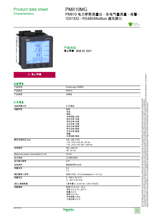
Product data sheetCharacteristicsPM810MGPM810 电力参数测量仪 - 全电气量测量 - 报警 -1DI/1DO - RS485/Modbus 通讯接口产品状态停止销售 : 四月 02, 2021i 停止销售主要信息产品系列PowerLogic PM800产品短名PM810产品类型功率表补充信息电能质量分析31次谐波测量类型电流 电压 频率功率因数 总值 视在功率 总值 有功功率 总值 无功功率 总值 视在功率 每相 有功功率 每相 无功功率 每相 能量功率因数 每相额定电源电压 [Us]125...250 V DC115...415 V AC 45...67 Hz 115...415 V AC 350...450 Hz电网频率350...450 Hz 45...67 HzMaximum power consumption in VA15 VA显示类型LCD背光显示显示器分辨率6 行采样频率每周波采样128点测量电流5 A 1 A模拟量输入类型电流 0.005...10 A (impedance <= 0.1 Ω)测量电压0…600 V AC P-P 0…347 V AC P-N(输入)通道数量1 数字量 0...5 mA 24...125 V AC/DC测量精度电流 0.5 % 0.5...10 A 电压 0.2 % 10...227 V 能量 0.2 % 频率 0.01 Hz 功率因数 0.002 三相功率 0.2 %T h e i n f o r m a t i o n p r o v i d e d i n t h i s d o c u m e n t a t i o n c o n t a i n s g e n e r a l d e s c r i p t i o n s a n d /o r t e c h n i c a l c h a r a c t e r i s t i c s o f t h e p e r f o r m a n c e o f t h e p r o d u c t s c o n t a i n e d h e r e i n .T h i s d o c u m e n t a t i o n i s n o t i n t e n d e d a s a s u b s t i t u t e f o r a n d i s n o t t o b e u s e d f o r d e t e r m i n i n g s u i t a b i l i t y o r r e l i a b i l i t y o f t h e s e p r o d u c t s f o r s p e c i f i c u s e r a p p l i c a t i o n s .I t i s t h e d u t y o f a n y s u c h u s e r o r i n t e g r a t o r t o p e r f o r m t h e a p p r o p r i a t e a n d c o m p l e t e r i s k a n a l y s i s , e v a l u a t i o n a n d t e s t i n g o f t h e p r o d u c t s w i t h r e s p e c t t o t h e r e l e v a n t s p e c i f i c a p p l i c a t i o n o r u s e t h e r e o f .N e i t h e r S c h n e i d e r E l e c t r i c I n d u s t r i e s S A S n o r a n y o f i t s a f f i l i a t e s o r s u b s i d i a r i e s s h a l l b e r e s p o n s i b l e o r l i a b l e f o r m i s u s e o f t h e i n f o r m a t i o n c o n t a i n e d h e r e i n .精度等级 2 无功电度 符合 IEC 62053-230.5S级 有功电度 符合 IEC 62053-220.2级 有功电度 符合 ANSI C12.20(输出)通道数量 1 数字(静态)通讯协议串口Modbus 38.4 kb通讯接口RS485数据记录最小/最大瞬时值时间间隔无内存警报GPS对时环境电磁兼容性振荡波抗扰度试验: 符合 IEC 61000-4-12谐波发射: 符合 IEC 61000-3-2传导和辐射干扰: 符合 EN 55011 B 类静电放电抗干扰: 类别3 符合 IEC 61000-4-2抗辐射: 类别3 符合 IEC 61000-4-3抗快速瞬变: 类别3 符合 IEC 61000-4-4抗浪涌: 类别3 符合 IEC 61000-4-5抗导电: 类别3 符合 IEC 61000-4-6振荡波抗扰度试验: 类别3 符合 IEC 61000-4-8抗电压偏移: 类别3 符合 IEC 61000-4-11闪烁发射: 符合 IEC 61000-3-3安装类型嵌入安装安装方式面板安装类型室内安装过电压类别IIIIP 保护等级IP30 后面: conforming to IEC 60529IP52 前面板: conforming to IEC 60529相对湿度90 % 在…上 40 °C污染等级2环境温度-25…70 °C贮存环境温度-40…85 °C工作海拔0...3000 m符合标准UL 508CSA C22.2 No 14IEC 61010-1产品认证cULus[RETURN]CE宽度96 Mm深度表 : 70 mm高度96 Mm净重0.6 Kg包装单位Unit Type of Package 1PCENumber of Units in Package 11可持续性产品类型Green Premium 产品欧盟ROHS指令符合欧盟ROHS声明合同保修保修单18 monthsProduct Life Status :End of commerc. - BlockPM810MG可替换为以下任意产品:METSEPM8240Power quality meter, PowerLogic PM8000, Standard, integrated display, 512 MB, 256 s/c数量 1替代日期: |。
如何正确操作使用测振仪 测振仪如何做好保养

如何正确操作使用测振仪测振仪如何做好保养如何正确操作使用测振仪测振仪也叫测震表振动分析仪或者测震笔,是利用石英晶体和人工极化陶瓷(PZT)的压电效应设计而成。
它广泛地被应用于机械制造、电力、冶车辆等领域。
工厂要实现设备管理现代化,应当积极推行先进的设备管理方法和实行以设备状态监测为基础的设备维护和修理技术。
设备状态监测及故障诊断技术是设备防备性维护和修理的前提。
特别是重工企业,工作连续性强及安全牢靠性要求高,通过状态监测。
测振仪也叫测震表振动分析仪或者测震笔,是利用石英晶体和人工极化陶瓷(PZT)的压电效应设计而成。
当石英晶体或人工极化陶瓷受到机械应力作用时,其表面就产生电荷。
接受压电式加速度传感器,把振动信号转换成电信号,通过对输入信号的处理分析,显示出振动的加速度、速度、位移值,并可用打印机打印出相应的测量值。
本仪器的技术性能符合国际标准ISO2954及中国国国家标准GB/T13824中,对于振动烈度测量仪中,正弦激励法振动标准的要求。
它广泛地被应用于机械制造、电力、冶车辆等领域。
那么,如何正确使用测振仪呢?珠海天创仪器公司为大家总结了以下几点:1、测振表测点选择:利用测振表,对紧要设备的轴承及轴向端点进行测试,并配有现场检测记录表,每次的测点必需相互对应。
2、测量周期:在设备刚刚大修后或接近大修时,需两周测一次;正常运行时一个月测一次;如遇所测值与上一次测值有明显变化时,应加强测试密度,以防突发事故而造成故障停机。
3、测量值判定依据:参照国际标准ISO2372、转速:600~1200r/min,振动测量范围:10~1000Hz。
通常在设备正常运行时,其检测速度值在 4.5~11.2mm/s(75kW以上机组)范围为监控使用,超过7.1mm/s以上就要考虑布置大修理。
这个数值的确定除考虑设备电机容量外,还要考虑工作连续性强、安全牢靠性高等方面。
总之,测振表与其它检测仪器搭配使用,有利对设备的运行状态进行分析。
D810 通用测力仪表使用手册说明书

D810通用测力仪表使用手册前言非常感谢您选用本公司产品!本手册包含产品的警告、注意事项、技术特性、功能特点、包装与外形、安装与接线、菜单结构、工作方式、通讯说明、参数表、保修说明、产品选型等内容。
为了使本产品长期保持最佳工作状态,在使用前,请您认真阅读操作手册,并妥善保管,以备随时查阅。
未经本公司许可,不得转载与复制本手册内容。
修订日期:20210122警告●超过使用环境条件要求,会影响仪表的测量指标和性能,严重时会造成仪表永久损坏!●本产品的安装、调试、维护应由具备资质的工程技术人员操作。
●本公司不承担除产品本身以处的任何直接或间接损失。
●本公司保留未经通知即更改产品说明书的权利。
●请不要使用在原子能以及与生命相关的医疗器械设备上。
●为了防止浪涌发生,请在产品的输入输出信号线上,添加适当的浪涌抑制电路。
●为了防止仪表损坏和防止机器故障,请在与本仪表连接的电源线或大电流容量的输入输出线上,安装适当容量的保险丝类安全断路器件,保护仪表。
●请不要将金属片或导线碎屑混入本产品中,以免导致触电、火灾、故障。
●请确实地拧紧端子螺丝,如果不完全拧紧,可能导致触电、火灾。
●请务必在切断电源后再进行清洁。
●清洁时,请用干的软布擦去本产品的污垢。
请不要使用吸湿剂,否则可能导致变形、变色。
●请不要使用硬物擦蹭或敲打显示部分。
●本产品的安装、调试、维护应由具备资质的工程技术人员操作。
目录1.技术指标 (7)2.功能特点 (8)3.包装与外形 (9)3.1装箱内容 (9)3.2开孔尺寸图 (9)4.安装与接线 (10)4.1安装示意图 (11)4.2接线定义图 (12)5.菜单结构 (13)5.1主要画面说明 (13)5.2按键说明 (13)5.3主界面介绍 (14)5.4标定方式 (14)5.5功能操作 (15)6.工作方式 (17)6.1810-1常规工作模式:E026输入11 (17)6.2810-2峰谷值工作模式:E026输入12 (17)7.通讯说明 (18)7.1串口的设置 (18)7.2Modbus-RTU协议 (18)7.3主动发送协议 (21)7.4通讯可靠性问题 (21)7.5通讯常见问题 (23)8.参数表 (24)8.1功能参数表 (24)8.1.1方式1常规工作模式参数表 (24)8.1.2方式2峰谷值捕获参数表 (28)8.2通讯地址表 (32)9.保修说明 (36)10.产品选型 (36)1.技术指标●测量通道:5V供电,测量精度优于0.05%,测量速度10、20、80、320Hz,温漂小于10ppm。
奥马 SKR 振动测试仪产品指南说明书

e-mail:**************For latest product manuals:SHAKERSShop online atUser’sGuideSKR SeriesServicing North America:U.S.A.:Omega Engineering, Inc., One Omega Drive, P.O. Box 4047ISO 9001 CertifiedStamford, CT 06907-0047 USA Toll Free: 1-800-826-6342TEL: (203) 359-1660FAX: (203) 359-7700e-mail:**************Canada:976 BergarLaval (Quebec), Canada H7L 5A1Toll-Free: 1-800-826-6342TEL: (514) 856-6928FAX: (514) 856-6886e-mail:*************For immediate technical or application assistance:U.S.A. and Canada:Sales Service: 1-800-826-6342/1-800-TC-OMEGA ®Customer Service: 1-800-622-2378/1-800-622-BEST ®Engineering Service: 1-800-872-9436/1-800-USA-WHEN ®Mexico:En Español: 001 (203) 359-7803FAX: (001) 203-359-7807**************.mxe-mail:*****************Servicing Europe:Benelux :Managed by the United Kingdom Office Toll-Free: 0800 099 3344TEL: +31 20 347 21 21FAX: +31 20 643 46 43e-mail:**************Czech Republic:Frystatska 184733 01 Karviná, Czech Republic Toll-Free: 0800-1-66342TEL: +420-59-6311899FAX: +420-59-6311114e-mail:*****************France:Managed by the United Kingdom Office Toll-Free: 0800 466 342TEL: +33 (0) 161 37 29 00FAX: +33 (0) 130 57 54 27e-mail:**************Germany/Austria:Daimlerstrasse 26D-75392 Deckenpfronn, Germany Toll-Free************TEL: +49 (0) 7059 9398-0FAX: +49 (0) 7056 9398-29e-mail:*************United Kingdom:OMEGA Engineering Ltd.ISO 9001 CertifiedOne Omega Drive, River Bend Technology Centre, Northbank Irlam, Manchester M44 5BD England Toll-Free: 0800-488-488TEL: +44 (0)161 777-6611FAX: +44 (0)161 777-6622e-mail:**************.ukOMEGAnet ®Online ServiceInternet e-mail **************It is the policy of OMEGA Engineering, Inc. to comply with all worldwide safety and EMC/EMIregulations that apply. OMEGA is constantly pursuing certification of its products to the European New Approach Directives. OMEGA will add the CE mark to every appropriate device upon certification.The information contained in this document is believed to be correct, but OMEGA accepts no liability for any errors it contains, and reserves the right to alter specifications without notice.WARNING: These products are not designed for use in, and should not be used for, human applications.BEFORE USE:Please read the following instructions:Read the Manual first before operating the instrumentFor indoor use onlyAmbient temperature range +5°C to +40°CUse in a well-ventilated area.Relative humidity not exceeding 80%Mains supply fluctuation not exceeding 10%WarningALL UNITS MUST BE GROUNDEDCheck the line supply is sufficient to meet the power requirement of the unit!OverviewOrbital Shakers are one type of mixers that the sample trays (platform) are moving horizontally (parallel to) the unit. There are several types of movement: orbital, reciprocating, and refrained orbital, such as SKR series (orbital); MS series and vortex mixers (refrained orbital). The SKR mixers generate smooth orbital (circular) and turbulence effect on the liquid, creating good mix and aeration for the samples and suitable for mixing the samples in flask and other larger containers. The SKR is also widely used in liquid culture. However, the SKR is not suitable for small vials since more vigorous movement needed for mixing the liquid in small containers.The Micro‐plate shakers are developed for the mixing of small vials. The shakers generate agitation effect through refrained orbital movement.Figure 1: Overview of the lab scale orbital shaker (SKR‐202, Digital). 1 Electrical socket;2 Carriage platform;3 Main LED on Digital front panelFigure 2: Overview of the mini microplate shaker (SKR‐13, Analog). 1 Electrical socket;2 Slip‐proof platform;3 Main Switch on Analog front panelOperationAlways install the carrier or platform before turn on the machines. All platforms or carriers are shipped in pre‐installed status. For safety reason, please check all the locking screw and tighten again if necessary. The locking screws might be loosened during transportation!Place the machines on the flat and steady surface and keep away from other objects for safe operation.Check the electrical safety status and the power switch must be in “OFF” position before plug into the power outlet. The machines come with IEC electrical socket and double fuses for safety operation.Load the samples first before turning on the machine. Be aware of loading sample evenly and never overload the samples.Always start with low speed and gradually adjust the speed, especially for the analog model.For SKR series, use 200 rpm maximum at the high loading.There are two different types of control in the shakers: digital and analog. Both control modes can adjust the speed and timer of the shakers.1. Digital Control of Speed and TimersFigure 14: Overview of the front panel of the digital control mode. 1 Start/stopbutton; 2 Mode button; 3 Indicator beneath “rpm”; 4 Indicator beneath “time”;5 Digital Read out;6 On/Off switch and Adjustment for Time and SpeedThere are two buttons and one knob on the digital panel: The knob is the main switch for turning on the machine and adjusting the speed and timer; the mode button has the selection function to either adjust the timer or the speed; the start/stop button is used to start or stop the mixing process. The panel has LED numeric display and red indicators.6illuminate, and when pressing the mode button, the read indicators underneath the rpm and minute alternatively illuminate to show the status of display.1.1 Press the knob to turn on the unit. The LED display the number of last saved rpm and timer setting. And the indicator underneath the rpm illuminate, adjust the rpm by the knob to desired value. And move the illuminated indicator from underneath rpm to minute by pressing the mode button, the display will show the set timer and change to the desired timing value, and finally press the start/stop button to start the machine. If using the knob to turn off the machine, the set timer and speed will automatically be saved, and carry on the next time operation.1.2 Adjust the timer: press mode button until the indicator underneath of min illuminate, turn the knob to desired count‐down minute. To disable the timer, just turn the knob to ‐‐‐, the unit will continuously operate until manually stopping the unit. When the timer reaches to zero, the unit stops and sounds an alert.The default time unit is minute (displayed nn:nn), but when turning the knob over 99:99, it displays H:nn. The maximum set time is 9 hours, i.e. 540 min.1.3 The speed and timer can be adjusted during operation without stopping the machine. Suggest users to use lower speed to start the machine and adjust the speed to optimum mixing status slowly to avoid the spill or safety problems during the operation.2. Analog Control of Speed and TimersFigure 15: Overview of the front panel of the analog control mode. 1 Timer knob;2 Main switch;3 Speed knobThere are two knobs and one main switch on the front panel of the analog types of the mixers. The main switch has three stages function: ON, OFF and Timer. For continuous operation, place the switch to the “ON” position, and turn the rpm knob (on the right hand side) to desired speed. When using timer, place the switch to “Timer” position, and adjust the speed using speed knob. Before turning on the machine, please turn the speed knob all the way to the left hand side (minimum level)! And adjust the speed gradually.Maintenance and ServiceThis range of equipment only requires routine cleaning for the maintenance. Before cleaning, Always unplug the equipment from the electrical outlet. Use soft cloth with mild detergent to clean the surface of the equipment.Technical SpecificationSKR‐202 SKR‐204 SKR‐12 SKR‐14Speed range (rpm) Digital, 30 to300Digital, 30 to300Digital, 250 to1250Digital, 250 to1250Motion Orbital Orbital Orbital Orbital Timer (min) Digital, 540 Digital, 540 Digital, 540 Digital, 540 Orbit (mm ) 16 16 0.7 0.7 Maximum load(KG)10 10 1 1 Platform (mm) 335X335 220X220 306X306 220X220 Dimensions, (mm,WXLXH)360x420x270 240x300x160 360x420x160 240x300x160 Operationaltemperature (°C )+4 to +40 +4 to +40 +4 to +40 +4 to +40 Maximumhumidity80% 80% 80% 80% CO2 EnvironmentSafeyes yes yes yesNet weight (KG) 11 6 10 6Power supply 120V, 60Hz,50W120V, 60Hz,50W120V, 60Hz,50W120V, 60Hz,50WWARRANTY/DISCLAIMEROMEGA ENGINEERING, INC. warrants this unit to be free of defects in materials and workmanship for a period of 36 months from date of purchase. OMEGA’s WARRANTY adds an additional one (1) month grace period to normal three (3) year product warranty to cover handling and shipping time. This ensures that OMEGA’s customers receive maximum coverage on each product.If the unit malfunctions, it must be returned to the factory for evaluation. OMEGA’s Customer Service Department will issue an Authorized Return (AR) number immediately upon phone or written request. Upon examination by OMEGA, if the unit is found to be defective, it will be repaired or replaced at no charge. OMEGA’s WARRANTY does not apply to defects resulting from any action of the purchaser, including but not limited to mishandling, improper interfacing, operation outside of design limits, improper repair, or unauthorized modification. This WARRANTY is VOID if the unit shows evidence of having been tampered with or shows evidence of having been damaged as a result of excessive corrosion; or current, heat, moisture or vibration; improper specification; misapplication; misuse or other operating conditions outside of OMEGA’s control. Components in which wear is not warranted, include but are not limited to contact points, fuses, and triacs.OMEGA is pleased to offer suggestions on the use of its various products. However, OMEGA neither assumes responsibility for any omissions or errors nor assumes liability for any damages that result from the use of its products in accordance with information provided by OMEGA, either verbal or written. OMEGA warrants only that the parts manufactured by the company will be as specified and free of defects. OMEGA MAKES NO OTHER WARRANTIES OR REPRESENTATIONS OF ANY KIND WHATSOEVER, EXPRESSED OR IMPLIED, EXCEPT THAT OF TITLE, AND ALL IMPLIED WARRANTIES INCLUDING ANY WARRANTY OF MERCHANTABILITY AND FITNESS FOR A PARTICULAR PURPOSE ARE HEREBY DISCLAIMED. LIMITATION OF LIABILITY: The remedies of purchaser set forth herein are exclusive, and the total liability of OMEGA with respect to this order, whether based on contract, warranty, negligence, indemnification, strict liability or otherwise, shall not exceed the purchase price of the component upon which liability is based. In no event shall OMEGA be liable for consequential, incidental or special damages.CONDITIONS: Equipment sold by OMEGA is not intended to be used, nor shall it be used: (1) as a “Basic Component” under 10 CFR 21 (NRC), used in or with any nuclear installation or activity; or (2) in medical applications or used on humans. Should any Product(s) be used in or with any nuclear installation or activity, medical application, used on humans, or misused in any way, OMEGA assumes no responsibility as set forth in our basic WARRANTY/DISCLAIMER language, and, additionally, purchaser will indemnify OMEGA and hold OMEGA harmless from any liability or damage whatsoever arising out of the use of the Product(s) in such a manner.RETURN REQUESTS/INQUIRIESDirect all warranty and repair requests/inquiries to the OMEGA Customer Service Department. BEFORE RETURNING ANY PRODUCT(S) TO OMEGA, PURCHASER MUST OBTAIN AN AUTHORIZED RETURN (AR) NUMBER FROM OMEGA’S CUSTOMER SERVICE DEPARTMENT (IN ORDER TO AVOID PROCESSING DELAYS). The assigned AR number should then be marked on the outside of the return package and on any correspondence.The purchaser is responsible for shipping charges, freight, insurance and proper packaging to prevent breakage in transit.FOR WARRANTY RETURNS, please have the following information available BEFORE contacting OMEGA:1.Purchase Order number under which the productwas PURCHASED,2.Model and serial number of the product underwarranty, and3.Repair instructions and/or specific problemsrelative to the product.FOR NON-WARRANTY REPAIRS,consult OMEGA for current repair charges. Have the following information available BEFORE contacting OMEGA: 1. Purchase Order number to cover the COSTof the repair,2.Model and serial number of the product, and3.Repair instructions and/or specific problemsrelative to the product.OMEGA’s policy is to make running changes, not model changes, whenever an improvement is possible. This affords our customers the latest in technology and engineering.OMEGA is a registered trademark of OMEGA ENGINEERING, INC.© Copyright 2009 OMEGA ENGINEERING, INC. All rights reserved. This document may not be copied, photocopied,Where Do I Find Everything I Need for Process Measurement and Control?OMEGA…Of Course!Shop online at SMTEMPERATUREThermocouple, RTD & Thermistor Probes, Connectors, Panels & AssembliesWire: Thermocouple, RTD & ThermistorCalibrators & Ice Point ReferencesRecorders, Controllers & Process MonitorsInfrared PyrometersPRESSURE, STRAIN AND FORCETransducers & Strain GagesLoad Cells & Pressure GagesDisplacement TransducersInstrumentation & AccessoriesFLOW/LEVELRotameters, Gas Mass Flowmeters & Flow ComputersAir Velocity IndicatorsTurbine/Paddlewheel SystemsTotalizers & Batch ControllerspH/CONDUCTIVITYpH Electrodes, Testers & AccessoriesBenchtop/Laboratory MetersControllers, Calibrators, Simulators & PumpsIndustrial pH & Conductivity EquipmentDATA ACQUISITIONData Acquisition & Engineering SoftwareCommunications-Based Acquisition SystemsPlug-in Cards for Apple, IBM & CompatiblesDatalogging SystemsRecorders, Printers & PlottersHEATERSHeating CableCartridge & Strip HeatersImmersion & Band HeatersFlexible HeatersLaboratory HeatersENVIRONMENTALMONITORING AND CONTROLMetering & Control InstrumentationRefractometersPumps & TubingAir, Soil & Water MonitorsIndustrial Water & Wastewater TreatmentpH, Conductivity & Dissolved Oxygen InstrumentsM-5371/1113。
福禄克810振动诊断仪白皮书

Fluke 810 振动诊断仪技术应用文章当你当你立即立即立即需要答案时需要答案时给立即就需要答案的机械维修人员的最先进的故障 检测工具。
独特的诊断方法能帮助你迅速诊断机械 问题并且按重要性排序,振动分析师的专家意见尽 在你的掌控之中。
你为你的设施、你的团队和你的工作感到骄傲。
你尽自己所能以使得工作顺利进行,但是有时候你没有足够的时间或资源来完成需要的工作量,更不用说对机械维修预作安排。
使用Fluke 810振动诊断仪可以使你领先一步,通过简单的逐步操作,一次测量即可报告机器的故障,而无需以前测量的历史记录。
它将诊断结果、故障的严重性和修理建议组合在一起,助你做出有依据的修理决策,首先处理关键的问题。
Fluke 810 Fluke 810 振动振动振动诊断诊断诊断仪可用于以下场合仪可用于以下场合仪可用于以下场合:: • 检查设备故障,确定其根本原因• 在计划维修前后对设备进行检查,确定修理工作是否达到要求• 确保新设备安装良好• 提供机器状况的可靠证据,控制修理和更换费用 • 按照重要性排序和计划修理工作,提高工作效率 • 提前对可能出现的故障做出预测,控制各种零部件的库存•对新手或经验不足的机械师进行培训,提高整个团队的信心和技能特点和优点特点和优点::• 实时判断和定位实时判断和定位各种常见的机械故障各种常见的机械故障各种常见的机械故障((轴承轴承问问题、不对中对中、、不平衡不平衡、、松动等松动等))以便针对故障的根本原因安排维修工作,大大减少计划外停机时间• 故障的严重程度分为四个等级使你可以按重要性排序安排维修工作 • 维修维修建议建议帮助机械师采取正确的行动 • 自带自带体贴体贴体贴的帮助的帮助为新用户提供实时的使用指南和使用技巧说明• 2 GB 可扩展的可扩展的内存内存为储存设备的各种数据提供足够大的空间• 自检功能确保最佳性能,更长的工作时间• 激光转速表精确测定机器的转速使诊断工作更准确• 三轴加速度计与单轴加速度计相比减少三分之二的测量时间•Viewer PC 软件扩展了数据储存和跟踪能力诊断诊断参数参数参数 标准故障不平衡、松动、不对中或轴承问题。
MIL-STD-810中低限完整性振动试验的正确使用
MIL-STD-810中低限完整性振动试验的正确使用
朱广荣
【期刊名称】《军用标准化》
【年(卷),期】1997(000)002
【总页数】4页(P36-39)
【作者】朱广荣
【作者单位】不详;不详
【正文语种】中文
【中图分类】V216.21
【相关文献】
1.中低频振动计算中有限元建模方法的讨论 [J], 魏强;朱祥
2.东菱振动振动世界--访苏州东菱振动试验仪器有限公司董事长王孝忠 [J], 冯峰;耿铭
3.利用撞击振动试验检测基础的完整性 [J], 陈永福
4.东菱振动振动世界——记苏州东菱振动试验仪器有限公司 [J], 樊宁
5.东菱振动振动世界--记苏州东菱振动试验仪器有限公司 [J], 樊宁
因版权原因,仅展示原文概要,查看原文内容请购买。
Fluke 805振动烈度(点检)仪

Fluke 805振动烈度(点检)仪
佚名
【期刊名称】《现代制造》
【年(卷),期】2012(000)042
【摘要】Fluke 805振动烈度(点检)仪是一款便携式多功能振动评估工具,可提供有关轴承和电动机及其他旋转设备总体状态的量化信息。
对于一线机械故障维修团队来说,Fluke 805是一款理想的工具,可为团队人员提供可靠及可重复的旋转设备测量。
【总页数】1页(P86-86)
【正文语种】中文
【中图分类】V243
【相关文献】
1.福禄克公司新品Fluke805振动烈度(点检)仪对振动评估进行了重新定义 [J],
2.新品Fluke805振动烈度(点检)仪对振动评估进行了重新定义 [J],
3.福禄克新产品Fluke 805振动烈度(点检)仪面市 [J],
4.福禄克公司推出新品Fluke 805振动烈度(点检)仪 [J],
5.新品Fluke805振动烈度(点检)仪对振动评估进行了重新定义检查机械设备的机械状态提供多种测试手段实现一流的可重复性和准确性 [J],
因版权原因,仅展示原文概要,查看原文内容请购买。
- 1、下载文档前请自行甄别文档内容的完整性,平台不提供额外的编辑、内容补充、找答案等附加服务。
- 2、"仅部分预览"的文档,不可在线预览部分如存在完整性等问题,可反馈申请退款(可完整预览的文档不适用该条件!)。
- 3、如文档侵犯您的权益,请联系客服反馈,我们会尽快为您处理(人工客服工作时间:9:00-18:30)。
安装选项
1
传感器位置编号
顶部/底部
2 3
粘合剂 柱头 螺栓 磁铁
侧面
传感器位置沿着能量流动方 向安排。
端部
电动机竖直安装 端部 前面/后面
测量提示
• 如果驱动电动机 > 40 HP (30 kW) 并且 > 40 英寸 (102 cm),则要从动力传 动系统中每一组件测量两次。如果不是这样,则每一组件测量一次就足够了。 • 将三轴传感器放在尽可能靠近机器轴承的坚固的金属表面上(不要放在风扇护 罩或者散热片上)。在不同的时间,使用相同的位置和传感器方向,确保得到 一致的诊断。 • 可能的话,将传感器附于清洁、平坦、裸露的金属表面上。 侧面 • 传感器电缆位置应尽可能与驱动轴平行或垂直。 • 拿紧传感器,在试验表面上小心滚动传感器,以使撞击可能降到最低限度。
可能的话,放在 1 和 2 处。
可能的话,放在 2 处。
典型的皮带驱动 卧式风扇
典型的皮带驱动 泵
典型的轴流式风扇
将传感器定位于 3 处。 将传感器定位于 4 处。
• 如果位置 1 或 2 不可用,则将传感器沿侧面向下移动 90°,从电动机顶部移到 1A 和 2A 处。 • 如果 1A 或 2A 不可用,则可能的话,将传感器移动到 电动机的端部,到 1B 或 2B 处。
是
是
首选位置:在 3 和 4 处的每 一个轴台的顶部。
否
电动机是否 > 40 HP(30 kW)?
否
二级减速齿轮 内部视图
首选位置: • 第一个轴承在 3 处的输入 轴,最好是推力轴承上。 • 最后一个轴承在 5 处的输 出轴上。
用螺栓将轴承所固定到的板的下侧 是否易近?
测量 1 和 2 处。
只测量 2 处。
将板下面的传感器直接定 位于轴承下面,在 3A 和 4A 处的安装螺栓之间。
取下防护罩,在 3 和 4 处的轴台上进行测量。
卧式外悬连接的泵
首选泵位置: • 将传感器放在尽可能靠近轴承处,最 好在 3 和 4 处的顶部。 • 如果 3 不易接近,则在 4 处测量。
如果 2 不可用,则将传感器沿电动机侧面向下移 动到 2A 处。
是 否
风扇
典型的汽封排放扇
在 3 和 4 处的首选位置 注意:如果外壳顶部难以接 近,则选择外壳侧面上的位 置。 将传感器定位于 4 处。 泵运转是否 > 2000 GPM?
典型的带托架轴承的风扇
在 3 和 4 处的首选位置 注意:由于较长的轴和托架轴承而产生 的较大隔振,要求在两个风扇轴承位置 处进行测量。
中等 严重
测量位置
极严重
RPM Hz
轴承类型
PN 3464999 January 2010, Rev. 1, 4/10 (Simplified Chinese) © 2010 Fluke Corporation. All rights reserved. Printed in USA.
电动机输入(驱动器)
连接的电动机
是 否
变速装置
皮带/链条驱动的机器
电动机是否 > 40 HP(30 kW)? 将传感器定位于 3 和 4 处的每一个轴台风扇轴承或 者轴承外壳(泵)上。 将传感器定位于 4 处。 注意:支持电动机和风扇的 螺杆或焊接支杆应该延长到 导管。将传感器放在结构杆 或支杆上。
从动组件
离心泵
典型的卧式泵
快速参考 指南
传感器位置
A = 轴向 R = 径向 T = 切向
严重度等级
轻度
kW HP = 非美制 = 美制
没有建议维修措施。在维护之后,重新测试机器并监测状况。 (数月甚至达 1 年)— 不要求立即采取维修措施。增加测量的 频率,并监测机器的状况。 (数周)— 在下一次计划的停机或维护周期中,采取维护措施。 (数天)— 要求立即采取措施。考虑现在关闭设备和采取维修措 施,以避免故障。
典型的立式泵
是
泵运转是否 > 3000 GPM?
否
典型的通风机/强迫轴鼓风机
轴台轴承上是否适当放置了 防护罩?
否
变速箱 电动机紧密连接的泵和风扇
是
将传感器定位于 3 处。
将传感器定位于 4 处。 将传感器定位于 4 处。 注意:如果在 4 处的泵自由 端推力轴承难以接近或者隐 蔽在系统液中,则将传感器 定位于 3 处。
单级压缩机(螺杆)
3 和 4 的首选位置是驱动轴 的顶部(外螺纹螺杆)并尽 可能靠近轴承。
