P4221-AP120中文资料
P4221-FQ120中文资料

60PPR 96PPR 150PPR 180PPR 200PPR 240PPR 250PPR 256PPR 270PPR 300PPR 360PPR 480PPR 500PPR 512PPR
120PPR 192PPR 300PPR 360PPR 400PPR 480PPR 500PPR 512PPR 540PPR 600PPR 720PPR 960PPR 1000PPR 1024PPR
240PPR 384PPR 600PPR 720PPR 800PPR 960PPR 1000PPR 1024PPR 1080PPR 1200PPR 1440PPR 1920PPR 2000PPR 2048PPR
7
Programming of Switches: \CCW=set to left; | Cntr=set center; /CW=set to right Note: for SW5 (right hand column PPR x 4) Time Settings: CW=other columns; Cntr=5-10µsec; CCW=25-35µsec
H e r c u l e s
6000 Series
4000 Series
For the latest specifications visit our website
元器件交易网
Hercules Encoders “Value Added” Programmable Encoder
6
Series 4000 and 6000 Programmable Encoders
Standard Features • 4000 Series - Space-Saving Enclosure, 1-1/2"D x 3"H x 3"W, 25 to 4096 PPR. • 6000 Series - Internal Space for 3 Separate Encoders, 25 to 4096 PPR. • Built-In Anti-Jitter Circuitry. • Operating Voltage Flexibility - 8 to 28Vdc, 5Vdc with TTL Outputs and Line Drivers, etc. • Low Supply Current Requirements - Only 50 Milliamperes per Encoder • Extra Heavy Duty 1/2"D Shafts - Optional
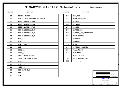
技嘉P4主板电路图
U1A 6 HA[3..16] HA[3..16] HA16 HA15 HA14 HA13 HA12 HA11 HA10 HA9 HA8 HA7 HA6 HA5 HA4 HA3 HADSTB0HREQ4HREQ3HREQ2HREQ1HREQ0N5 N4 N2 M1 N1 M4 M3 L2 M6 L3 K1 L6 K4 K2 L5 H3 J3 J4 K5 J1 AB1 Y1 W 2 V3 U4 T5 W 1 R6 V2 T4 U3 P6 U1 T2 R3 P4 P3 R2 T1 R5 A16 A15 A14 A13 A12 A11 A10 A9 A8 A7 A6 A5 A4 A3 ADSTB0 REQ4 REQ3 REQ2 REQ1 REQ0 A35 A34 A33 A32 A31 A30 A29 A28 A27 A26 A25 A24 A23 A22 A21 A20 A19 A18 A17 ADSTB1
G1 AC1 V5 AA3 G2 L25 K26 K25 J26 U6 W 4 Y3 H6 D2 H5 E2 H2 F3 E3 AC3 W 5 G4 V6 AB25 F4 G5 F1 AB2 J6
HADS-
HADS- 6 R3
BNR-
BNR- 6 39/6/X
C
C
VCORE
BC19 10U/12/X
10U/12/X5R 10U/12/X
6 HA[17..31]
HA[17..31] HA31 HA30 HA29 HA28 HA27 HA26 HA25 HA24 HA23 HA22 HA21 HA20 HA19 HA18 HA17 HADSTB1-
VCORE
HINITHLOCKHLOCK- 6
HINIT- 13,15
NSK轴承型号系列代号含义

需要查询的 轴承型号
序号 1 2 3 4 5 6 7 8 9 10 11 12 13 14 15 16 17 18 19 20 21 22 23 24 25 26 27 28 29 30 31 32 33 34 35 36 37 38 39 40 41
代号 内容
AH 推卸套代号
B
NC 防滑移轴承(金属圈)
NCX 防滑移轴承(金属圈)
NRX 带特殊尺寸止动环
NRZ 单侧带钢板防尘盖,同侧带止动环(与ZNR相反)
P
带调心座圈的圆柱滚子轴承(特殊调心座设计)
P4Y 精密轴承精度等级为4Y级(内,外径尺寸公差特殊,其余为P4级精度)
PMK() PMK(X)密封轧机辊颈轴承润滑脂牌号(PALMAX RBG),()内为X,Y等管理记号
58
W
英制圆锥棍子轴承中套圈有凹槽(可表示)
59
WA 圆锥棍子轴承强化型保持架
60
W507 调心滚子轴承外圈带油孔油槽(E4+耐高温热处理+特殊管理规格)
61
W509 调心滚子轴承的特殊规格(E7+高温热处理+特殊管理规格)
62
X
内径、外径、宽度三者之一作±1以内的变更
63
X
推力轴承中轴圈外径小于座圈外径
MC2
193 194
MC3 MC4
小型,微型球轴承
195
MC5
196
MC6
197
CM
198
CT
199
CM
200
CG
201
CA
202
省略 JIS 0级
203
P6 JIS 6级
1202P中文资料

Document Number: 63055For any questions, contact: foil@1202Vishay Foil ResistorsBulk Metal ® Foil TechnologyPrecision Trimming Potentiometers, 1 1/4 Inch Rectilinear, RJ12 Style, Designed to Meet or Exceed The Requirements of MIL-PRF-22097, Char. FNote1.See Figures 1 and2.FEATURES•Temperature coefficient of resistance (TCR): ± 10 ppm/°C maximum 3) (- 55 °C to + 150 °C ref. at + 25 °C); through the wiper 4); ± 25 ppm/°C•Load life stability: 0.1 % typical ΔR, 0.5 %maximum ΔR under full rated power at + 85 °C for 2000 h•Settability: 0.05 % typical; 0.1 % maximum•Setting stability: 0.1 % typical; 0.5 % maximum, ΔSS •Power rating: 0.5 W at + 85 °C •Resistance range: 2 Ω to 20 k Ω•“O“-ring prevents ingress of fluids during any board cleaning operation•Electrostatic discharge: above 25 000 V •Terminal finishes available: gold platedNotes†Under full rated power of 0.5 W at + 85 °C.•Refer to page 4 for footnotes.* Pb containing terminations are not RoHS compliant, exemptions may applyTABLE 1 - MODEL SELECTION †MODELTERMINATIONSTYLE AVERAGEWEIGHT(g)POWERRATING at + 85 °C AMBIENTNO. OFTURNS1202P-In line PC pins 2.50.5 W25 ± 2Y -staggered PC pins 1)2.5L-flexible wire leads3.3LB-flexible wire leadswith bushings5.1TABLE 2 - VALUES VS. TOLERANCESSTANDARD RESISTANCE VALUES (in Ω)STANDARD TOLERANCES2, 5, 10± 10 %2), ± 20 %20, 50, 100, 200, 250, 500, 1K, 2K, 5K, 10K, 20K5 %, 10 %TABLE 3 - 1202 (RJ12) SERIES ELECTRICAL SPECIFICATIONSTemperature Coefficient of Resistance (TCR)end-to-end 3)± 10 ppm/°C maximum (- 55 °C to + 25 °C)± 10 ppm/°C maximum (+ 25 °C to + 150 °C)2 Ω, 5 Ω, 10 Ω, 20 Ωthrough the wiper 4)± 20 ppm/°C ± 25 ppm/°CStabilityload life at 2000 h †load life at 10000 h †0.1 % typical ΔR; 0.5 % maximum ΔR 0.1 % typical ΔR; 1.0 % maximum ΔR Power Rating 5)0.5 W at + 85 °CSettability 0.05 % typical; 0.1 % maximum Setting Stability0.1 % typical; 0.5 % maximum ΔSS Contact Resistance variation - CRV (noise) 3 Ω typical; 10 Ω maximum Hop-off0.25 % typical; 1.0 % maximum High-Frequency Operation Rise time Inductance Capacitanceto 100 MHz 10 ns at 1 k Ω0.08 µH typical 0.5 pF typical Operating Temperature Range- 55 °C to + 150 °CTABLE 4 - MECHANICAL SPECIFICATIONSAdjustment Turns 25 ± 2Case Material Glass fortified diallyl-phthalate (DAP); black Mechanical StopsWiper idles - no discontinuityShaft Torque 8 oz. in. maximum; 3 oz. in. typical Internal Terminations All welded - no fluxBacklash0.05 % typical1202Vishay Foil Resistors Bulk Metal® Foil Technology Precision TrimmingPotentiometers, 1 1/4 Inch Rectilinear, RJ12 Style, Designed toMeet or Exceed The Requirements of MIL-PRF-22097, Char. F Array For any questions, contact: foil@ Document Number: 63055Document Number: 63055For any questions, contact: foil@1202Bulk Metal ® Foil Technology Precision Trimming Potentiometers, 1 1/4 Inch Rectilinear, RJ12 Style, Designed to Meet or Exceed The Requirements of MIL-PRF-22097, Char. FVishay Foil Resistors1202Vishay Foil ResistorsBulk Metal ® Foil Technology Precision TrimmingPotentiometers, 1 1/4 Inch Rectilinear, RJ12 Style, Designed to Meet or Exceed The Requirements of MIL-PRF-22097, Char. F For any questions, contact: foil@Document Number: 63055Notes1.Preferred Termination style for current 1-1/4 inch rectilinear trimmers (staggered PC pins present a sturdier mounting arrangement for shock, vibration, and impact situations).2.10 W at ± 5 % available on special order.3.Maximum TCR applies to the 3 σ (sigma) limit or 99.73 % of a production lot. (Measured end-to-end with wiper off the element.)4.Measurements of TCR through the wiper are influenced more by setting stability and the percentage of the total resistance in use (at the wiper) than by fundamental resistance change due to temperature alone. The parameter shown in Table 3 is a 2 σdistribution typifying the behavior of the device when used with 40% or more of the total resistance in use.5.Derated linearly from full power at + 85 °C to zero (0) W at +150 °C. See Figure 3 in this data sheet.6.All ΔR’s are measured to the tolerance specified + 0.01 Ω.7.Whichever is greater.8.Load-Life test performed at nominal rated power, 0.5 W, at +85 °C.Special Available Options:Special markingSpecial lengths for lead wires (L, LB Style)Hooked leadsAlternate bushing and PC combinationsPower conditioning and screening operations VISHAY TRIMMERS ARE INSPECTED 100 % for:•Short-time overload (6.25 x rated power for 5 s on; and for 30 s off - 3 cycles)•Immersion•Resistance tolerance check •End resistance •Visual-mechanical•Dynamic tests for continuity, CRV By Sample for:•TCR •DWVTABLE 5 - COMPARISONMIL-PRF-22097/2 CHARACTERISTIC F 7)1202 MAXIMUM (Worst Case)TEST GROUP IVisual and mechanical Total resistanceActual effective electrical travel End resistanceContact resistance variation - CRV (noise) Dielectric withstanding voltage - DWV (atmospheric and barometric pressure) Insulation resistance Shaft torque Thermal shock No failures ± 10 %17 to 27 turns ± 2 % or 20 Ω7)± 3.0 % or 3 Ω7)Per MIL-STD-202, methods 301 and 105≥ 1000 M Ω8 oz. in. maximum± 1.0 %No failures ± 10 %25 ± 2 turns2 Ω3 Ω typical, 10 Ω maximumPer MIL-STD-202, methods 301 and 105≥ 1000 M Ω8 oz. in. maximum± 1.0 %TEST GROUP IIResistance temperature characteristic - TCR Moisture resistanceContact resistance variation - CRV (noise)± 0.01 % (± 100 ppm/°C)± 1.0 %3.0 % or 3 Ω7)± 0.001 % (± 10 ppm/°C)± 0.5 %3 Ω typical, 10 Ω maximum TEST GROUP IIIShock (specified pulse)Vibration (high-frequency)Contact resistance variation - CRV (noise)Salt spray± 1.0 %± 1.0 %± 3.0 % or 3 Ω7)No corrosion ± 0.5 %± 0.5 %3 Ω typical, 10 Ω maximumNo corrosion TEST GROUP IV Solder heatLife (1000 h at + 85 °C)8)Contact resistance variation - CRV (noise)± 1.0 %± 2.0 %± 3.0 % or 3 Ω7)± 0.05 %± 0.5 %3 Ω typical, 10 Ω maximum TEST GROUP VLow-temperature operation High-temperature exposureContact resistance variation - CRV (noise)± 1.0 %± 2.0 %± 3.0 % or 3 Ω7)± 0.5 %± 0.5 %3 Ω typical, 10 Ω maximum TEST GROUP VI Rotational lifeContact resistance variation - CRV (noise)Terminal strength ± 2.0 %± 3.0 % or 3 Ω7)2 lbs± 2.0 %3 Ω typical, 10 Ω maximum2 lbs TEST GROUP VIISolderability (excluding termination L)Immersion (excluding termination L)MIL-STD-202 method 208No continuous stream of bubblesMIL-STD-202 method 208No continuous stream of bubbles TEST GROUP VIII Fungus MIL-STD-810 method 508No mechanical damageMIL-STD-810 method 508No mechanical damageDocument Number: 63055For any questions, contact: foil@1202Bulk Metal ® Foil Technology Precision Trimming Potentiometers, 1 1/4 Inch Rectilinear, RJ12 Style, Designed to Meet or Exceed The Requirements of MIL-PRF-22097, Char. FVishay Foil Resistors Note* For non-standard requests, please contact Application Engineering.TABLE 6 - GLOBAL PART NUMBER INFORMATIONNEW GLOBAL PART NUMBER:Y5050500R000K0L (preferred part number format)DENOTES PRECISIONVALUE AER*YR = ΩK = k Ω0 = standard 1 - 999 = customPRODUCT CODE TOLERANCE PACKAGING 5050 = 1202L 0050 = 1202LB 0051 = 1202P 6050 = 1202PB 5051 = 1202Y 7050 = 1202YBJ = ± 5 %K = ± 10 %M = ± 20 %L = bulk packFOR EXAMPLE: ABOVE GLOBAL ORDER Y5050 500R000 K 0 L:TYPE: 1202L VALUE: 500.0 ΩABSOLUTE TOLERANCE: ± 10.0 %AER: standardPACKAGING: bulk packHISTORICAL PART NUMBER:1202L 500R00 K B (will continue to be used)1202L 500R00K B MODEL RESISTANCE VALUETOLERANCE PACKAGING 1202L 1202LB 1202P 1202PB 1202Y 1202YB500.0 ΩJ = ± 5 %K = ± 10 %M = ± 20 %B = bulk pack05050R 00Y 5K 00LDisclaimer Legal Disclaimer NoticeVishayAll product specifications and data are subject to change without notice.Vishay Intertechnology, Inc., its affiliates, agents, and employees, and all persons acting on its or their behalf (collectively, “Vishay”), disclaim any and all liability for any errors, inaccuracies or incompleteness contained herein or in any other disclosure relating to any product.Vishay disclaims any and all liability arising out of the use or application of any product described herein or of any information provided herein to the maximum extent permitted by law. The product specifications do not expand or otherwise modify Vishay’s terms and conditions of purchase, including but not limited to the warranty expressed therein, which apply to these products.No license, express or implied, by estoppel or otherwise, to any intellectual property rights is granted by this document or by any conduct of Vishay.The products shown herein are not designed for use in medical, life-saving, or life-sustaining applications unless otherwise expressly indicated. Customers using or selling Vishay products not expressly indicated for use in such applications do so entirely at their own risk and agree to fully indemnify Vishay for any damages arising or resulting from such use or sale. Please contact authorized Vishay personnel to obtain written terms and conditions regarding products designed for such applications.Product names and markings noted herein may be trademarks of their respective owners.元器件交易网Document Number: 。
SKIIP1242GB120-4D中文资料
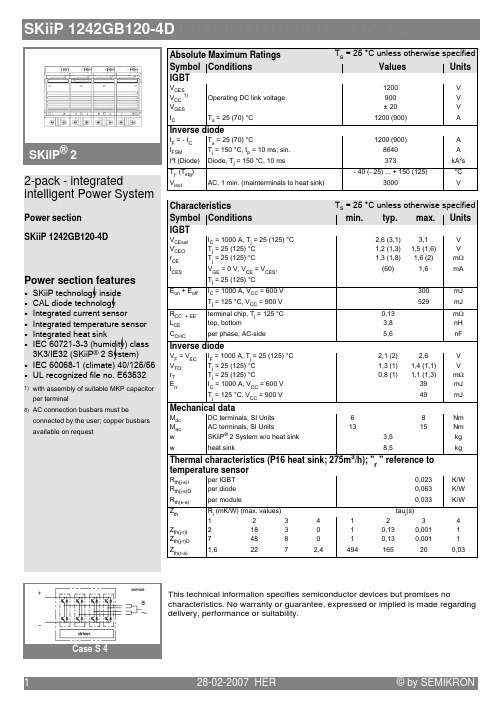
This technical information specifies semiconductor devices but promises no characteristics. No warranty or guarantee, expressed or implied is made regarding delivery, performance or suitability.
1
/
min. typ. max. Units
: :<
8 # C 7B 8 ", &#",' 9 7B 8 ", &#",' 9 7B 8 ", &#",' 9
:? 8 :C : 8 :C
7B 8 ", &#",' 9
28-02-2007 HER
© by SEMIKRON
元器件交易网
SKiiP 1242GB120-4D INTEGRATED DRIVER, SENSORS
SKiiP® 2
Absolute Maximum Ratings Symbol Conditions
:# :" :J
C
=$2 5
& '
<5
<5
5
5( :< :#" /1 / 7 &7 '
2.
#, : 1
PS-12024中文资料

I/P-O/P, I/P-FG, O/P-FG:100M Ohms/500VDC EMI CONDUCTION & RADIATION Compliance to EN55011,EN55022 (CISPR22) Class B Compliance to EN61000-3-2,-3 HARMONIC CURRENT EMS IMMUNITY MTBF Compliance to EN61000-4-2,3,4,5,6,8,1 1, ENV50204, EN55024, EN61000-6-2 (EN50082-2) Heavy industry level, criteria A 136.8Khrs min. MIL-HDBK-217F (25 ) 65.5*125.2*100mm (W*H*D) 0.79Kg; 20pcs/16.5Kg/1.1CUFT
OTHERS
NOTE
DIMENSION PACKING
1. A ll parameters N OT s pecially mentioned a re measured a t 230VAC i nput, r ated load a nd 25 of ambient temperature. 2. R ipple & n oise a re measured a t 20MHz o f bandwidth by using a 1 2" twisted pair-wire terminated with a 0 .1uf & 4 7uf parallel capacitor. 3. T olerance : i ncludes s et up tolerance, line regulation a nd load regulation. 4. T he power s upply is c onsidered a c omponent which will be installed into a f inal equipment. T he final equipment must be re-confirmed that it still meets E MC d irectives.
物流工程SLP方法习题课内容

表1:零件产量及重量
零件号 每天
单件
产量(箱)重量(kg)
1
2000
0.5
2
2000
9.0
3
2000
0.5
4
2000
15.0
5
2000
3.75
表2 :工艺路线
零件号 工艺路线
1
RABDCFS
2
RBDCAS
3
REFBACDS
4
RFACDS
5
RCADS
解:用从至表进行物流分析 1)首先求当量物流量
零件号 每天产量 单箱重 (箱) (kg)
1
2000
0.5
总重 当量重量 (kg) 1000 1
2
2000
9.0
18000 18
3
2000
0.5
1000 1
4
2000
15.0 30000 30
5
2000
3.75 7500 7.5
2):作业单位物流量从至表
至
从
R
A
R
1
BC D E F S
18 7.5
1 30
A
1 1+30 7.5
18
B
1
1+18
• 方案2旳所有时间等于或不不小于流水线需求节拍。使用这种配置, 在正常作业旳状况下,该流水线每天可生产大概240个装配件。同步 应当注意到,在作业40之后旳生产看板不再需要,由于作业周期时间 目前少于需求节拍。
课堂练习:
某企业生产5种零件,由产量预测及查询 BOM表得到产量及重量信息,见表1; 查询各个零件旳工艺路线卡得到工艺路 线信息见表2,试进行物流分析。
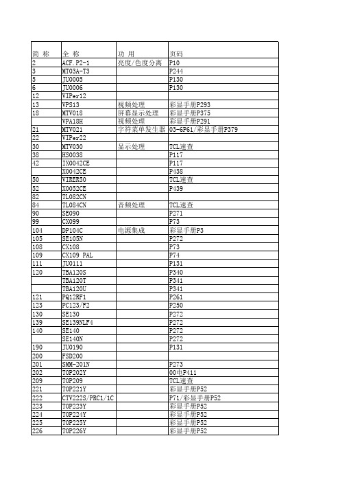
IC目录大全
LM1205
视频处理
LM1207
视频处理
LM1208
视频处理
LM1209
视频处理
TB1212N
CXA1213S
TA1216AN
音频处理
NCP1217
TA1222N
MN12C25D
TA1226N
TB1227N
TB1231AN
TLS1233
音频处理
*PC1238V
音频功放
TB1238AN
TV处理器
TB1240N\06-3P63 TV处理器
TDA1517/P TDA1521A TDA1524A TDA1526 TDA1543 CXA1545AS CXA1587S CKP1604S CXA1644P CXA1649M TDA1670 TDA1675 D16F78B CXA1688M CXA1688M SBA1765-01 CXA1779P *PC1830GT C1853CT *PC1853-01 S1854 *PC1883 *PC1884 *PC1885 UPC1891ACY TDA1904
LM1296
屏幕显示处理
TDA1303
TA1304N
音频处理
MC1327
TA1343
音频处理
06-2P62 P99 TCL速查 TCL速查 彩显手册P84 彩显手册P84 P354/彩显维修手册P111 彩显维修手册P114 07-11P32 彩显维修手册P229 彩显维修手册P233 彩显维修手册P233/08-8P4 彩显维修手册P233 彩显维修手册P233 P335 电2000P840 TCL速查 08-8P3 电2000P847 O223 P290 P337 P338 彩显手册P288 P447 P338/TCL速查/06-3P64 00电P225/TCL速查/08-6P15 P447 07-10P10 03-1P7/06-9P36P61
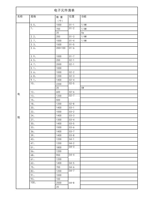
电子元件清单
预调
12
长柄可调
20K
60
26-4
预调
0
长柄可调
33 K
100
26-5
47K
100
26-6
50K
0
27-1
100K
100+100
27-2
预调
3
双联可调
200K
40
27-3
预调
15
微调
微调
330K
16
27-4
微调
470K
26
27-5
长柄可调
电阻
500K
110
27-6
预调
16
微调
1M
70
28-1
182P
1000
41-2
183P
400+100
41-3
184P
1000
41-4
41-5
41-6
561P
1000
41-7
562P
1000
41-8
563P
1000
41-9
564P
1000
41-10
681P
1000
42-1
682P
1000
42-2
683P
1000
42-3
501P
200+100
42-4
502P
22
3300 u/50v
1
33-6
3300 u/25 v
100
3300u/16V
23
4700u/25v
100
34-1
4700u/16V
12
1P
V300LA20AP中文资料

Device Ratings and Specifications
RoHS Pb
LEAD-FREE AND RoHS COMPLIANT MODELS
PART NUMBER
BRANDING
STANDARD MODELS
MODEL SIZE
DISC
PART
DIA.
NUMBER BRANDING (mm)
1501
7
V150LA2P
P1502
V150LA2
1502
7
V150LA5P
P1505
V150LA5
1505
10
V150LA10AP P150L10 V150LA10A
150L10
14
V150LA20AP P150L20 V150LA20A
150L20
20
V150LA20BP P150L20B V150LA20B
VM(AC)RMS . . . . . . . . . . . . . . . . . . . . . . . . . . . . . . . . . . . . . 130V to 1000V • No Derating Up to 85oC Ambient • Available in Tape and Reel or Bulk Pack
AGENCY APPROVALS: Standard and Lead-free parts recognized under the components program of Underwriters Laboratories. Certified by CSA, VDE and CECC.
AGENCY FILE NUMBERS: UL E75961, E56529 (Lead-free pending), E135010 (Lead-free pending); CSA LR91788; VDE 116895E; CECC 42201-006.
VAMP221_technical说明书

VAM P 221
电弧光保护系统 技术手册
VAMP 221
目录
1. 介绍 .....................................................................................................4 1.1. 用途 ..............................................................................................4 1.2. 主要特性 ......................................................................................4
3. 应用举例 ...........................................................................................12 3.1. 选择光纤传感器解决方案, 3 个进线, 3 个保护区, 使用 CBFP … … … … … … … … … … … … … … … … … … … … … … … ..12 3.1.1. 功能系统描述...................................................................13 3.1.2. 系统元件...........................................................................13 3.1.3. 系统配置...........................................................................13 3.1.4. 应用举例测试...................................................................17 3.2. 选择传感器解决方案, 2 个进线, 2 个保护区, 使用 CBFP ....18 3.2.1. 功能系统描述...................................................................20 3.2.2. 系统元件...........................................................................20 3.2.3. 系统配置...........................................................................20 3.2.4. 系统测试...........................................................................24 3.3. 选择光纤、传感器解决方案, 多个进线, 多个保护区, 使用 CBFP ........................................................................................26 3.3.1. 功能系统描述...................................................................28 3.3.2. 系统元件...........................................................................29 3.3.3. 系统配置...........................................................................29 3.3.4. 系统测试...........................................................................33 3.4. 基于接地故障电流的电弧光保护电流测量 ............................34 3.4.1. 功能系统描述...................................................................34
便携式阀门执行器Green Power Line系列说明书

GREEN POWER LINE includes the full set of Portable Actuation devices for valves, penstocks and sluice gates equipped with a Li-ion battery engine, offered in two versions: APB120N and APB160N. The output torque (in Nm) and the related output speed (in RPM) of the APB devices are adjustable according to the finger pressure on the accelerator button: when fully pressed, the units operate at their continuous torque value, further reaching their maximum torque when facing resistance during the operation; above these values, a thermal circuit breaker will stop the engine until the next manual ‘reset’. Very simple and easy to use, these devices are the ultimate tool for water operators looking for power on particular sites, such as underground chambers, or in cas e of multiple ‘short’ daily i nterventions on valves and gates, as well as representing a valuable alternative to the ‘classic’ electrified fixed actuation systems.APB120N – Hikoki 36V Brushless engineTechnical dataMax torque : 137 Nm / 101,05 Ft/lbContinuous torque : 95 Nm / 70,06 Ft/lbOutput speed : 114 RPMEngine speed : 25000 RPMReduction ratio : 4,8/1+50/1Engine power : 1000 WBattery : Hikoki 18-36V 4,0 AhDimensions : 340x220x(h)360 mmWeight : 7,2 KgConnection : Q24x24x(h)5 mmAPB160N – Hikoki 36V Brushless engineTechnical dataMax torque : 176 Nm / 129,81 Ft/lbContinuous torque : 168 Nm / 123,91 Ft/lbOutput speed : 78 RPMEngine speed : 25000 RPMReduction ratio : 4,8/1+70/1Engine power : 1000 WBattery : Hikoki 18-36V 4,0 AhDimensions : 340x220x(h)360 mmWeight : 7,2 KgConnection : Q24x24x(h)5 mmAPB120N / APB160N features:(1) Hikoki 36V engine: based on ‘Brushless’ technology, it offers maximum efficiency, power and reliability in an 'eco-friendly' way, guaranteeing a very reduced energy consumption.(2) Gear case: composed by a primary bevel gear in Ergal alloy coupled in axis to a secondary micro-reducer, with the goal to ensure the APB device with sturdiness and high reliability over time.(3) Control Handle: with a practical and soft-grip anatomical shape, it includes the accelerator button and the selectable lever for the rotation on Left/Block/Right positions.(4) Hikoki 36V Battery connection: with a renewed design that makes everything very compact, ergonomic and balanced, it includes also an automatic LED light for night work.(5) Protection cover: made of painted stainless steel, it ensures strength and solidity to the APB device; at the same time, it guarantees the correct ventilation of all the internal electrical parts.(6) Side Handle: mountable on both left/right side of the tool, it facilitates the use of the APB tool to both left and right-handed operators.(7) Thermal circuit breaker: it’s the electrical protection of the tool against any overloads. In case of absorption higher than 16A, the breaker turns off the APB device (un til the manual ‘reset’ of the operator)(8) Anti-rotation Pin:adjustable in its plate, it guarantees a quick, safe and stable fixing of the pin itself during the connection between the APB actuator and the gate/valve.(8) Safety Split:galvanized and with its steel cable, it allows and easy and safe coupling between the APB device and the gate/valve to be moved.(9) Spindle: made of steel, it’s the point where the operator must install the proper bushing in order to transmit the rotation movement from the Portable Actuator to the bevel gear on the gate/valve.APB120N / APB160N Standard supply:(A) Plastic case : with internal shockproof foam padding on the inside, for an easy and safe transport of the APB device to the sites of the daily interventions.(B) N. 02 Hikoki Multivolt 18-36V li-ion batteries : from the latest generation series, they include triple power output (if compared to the previous models) and the convenient LED charge status indicator.The batteries are supplied along with the Hikoki Charger, including features as: fast charging system, USB connection, cooling fan and LED system indicating charging and/or any failure.(C) Shoulder Belt : it must be connected at the support bracket and it allows the operator to easily transport and handle the APB unit during the various stages on the intervention sites.(D) Anti-rotation Pin Set : in three different sizes and interchangeable, they always guarantee the correct and safe ‘block’ of the Portable Actuator to the gate/valve.Usage of the APB/APS Portable Valve Actuators on gates/valvesIn order to transfer the ‘rotation ’ from the Portable Actuator to a bevel gear installed on a gate/valve, it is necessary to install a Bushing (photo 1) on the actuator ’s spindle using the four screws supplied.After that, in consideration of the fact that the APB/APS devices produce a huge Nm output force, it is also necessary to install an Anti-Rotation Flange (photo 2) on the bevel gear of the gate/valve. This avoids the ‘snatch’ rot ation of the APB/APS tool while in operation and prevents any potential injuries to the operator.The safety system is completed by the Anti-Rotation pin and its Safety Split that allow to keep the actuator ‘locked in position’ whil e operating. This is a safety mechanism required by law. The manufacturing company is not responsible for any damage to people (o properties) resulting from its failure or incorrect use.Therefore, once the correct bushing has been installed on the APB/APS and the proper A-R flange on the bevel gear, all that’s left to do is to connect the bushing to the reducer’s shaft, make sure that the A-R pin enters the A-R flange, then close it using its safety split. Now, you are 100% ready to operate.Photo 3 shows this connection phase (this procedure is the same for both sluice gates/penstocks/valves)1. Bushings (to mount on the APB/APS)2. A-R Flanges (to mount on the bevel gear)3. Connection of the APB/APS to the gearbox shaftAbout interventions on multiple series of gates/valvesWhen planning to operate on several gates/valves with bevel gear shafts of different diameters, it is necessary to standardize them all by installing a series of Adaptors with male square 24x24mm that fits the ‘standard’ square 24x24mm female bushing on the APB/APS tool.All the Adaptors (photo 4) have a 24x24mm square male connection and a cylindrical female part of different sizes. It is therefore necessary to identify in advance which types are necessary, and then proceed with their installation along with the corresponding anti-rotation flange; after this installation work, it will be possible to operate on all gates/valves without continuous changes of bushing (photo 5). However, at this point it will no longer be possible to use the original hand-wheels. So, in order to perform manual interventions again, it will be necessary to use the Square 24mm Hand Crank , that combined with the Padlocking Kit allows also to lock the bevel gear on the gate/valve (photo 6) in order to avoid unauthorized movements.4. Q24x24 adaptor mounted on the bevel gear5. Connection of APB/APS to A-RFlange+Q24 adaptor6. Q24 hand crack + locking system on bevel gearManual emergency interventions on electric actuators‘Emergency operations’ are all those manual interventions, performed on Electrified Actuators in absence of electricity, using the small manual hand-wheel on the body of the actuator itself.With the aim of providing a full service to its Customers, Scapin has designed and created a series of custom kits to install on the emergency of the most common models of AUMA / BIFFI / DREHMO / ROTORK electrical actuators.The installation of these Emergency Kits is very simple: once the hand-wheel has been removed from the electric actuator, it will be sufficient to mount the adaptor and the anti-rotation flange using the supplied screws. After that, the emergency can be performed using an APB/APS device.Once the intervention has been completed and the Portable Actuator disconnected, it is possible to both remove the Emergency Kit, or leave it installed. On this last situation, it is possible to restore the manual hand-wheel as it was originally by mounting an appropriate Q24 adaptor (supplied with the kit) on it and then, if necessary, lock it using a removable padlock (see the photos below).The usage of the APB devices is highly recommended on Drehmo electric actuators, in order to not burden its emergency output shaft with excessive weight. On the other hand, Auma and Biffi actuators can be easily handled with all the APS devices.Emergency Kit on AUMA Electrict Actuator Emergency Kit on BIFFI Electrict Actuator Emergency Kit on DREHMO Electric ActuatorAPB/APS tool on AUMA Electrict Actuator APB/APS tool on BIFFI Electrict Actuator APB/APS tool on DREHMO Electric ActuatorVisit our YouTube Channel to see our HD videos showing the APB/APS devices at work。
工厂实战解析-注塑产品银丝银线的发生原因与解决方法

7/11
一~2、模具侧发生原因与解决方法:S130531案例
S130531排气不良 引发银线与产品表 面
排气不良引发银线(产品左侧)
左图是S130531因网孔多,排气不良 造成产品银线。 对策:必须模具PL面全周排气,且网 孔中必需打通气孔排至模具外,才 能有良好产品外观。
排气不良引发的银线(产品右侧)
3/11
一~1、银线发生原因与解决方法—射出机台侧
ABS塑料已烘干状态
ABS料未烘干状态 (水分蒸发造成多孔状)
经常发生
银线材料是 PMMA、ABS、 PC、PC+ABS等, 必须依材料厂 商指示烘料温 度及时间,完 全烘干,同时 要考虑烘料机 料桶的能力。 左图是ABS烘 干的未烘干的 材料状况。
其原因有塑料 干燥不完全的水分、 挥发物、或塑料热 分解、空气卷入、 料口太小等原因皆 会造成银线。
2/11
一、银线的发生原因
成型条件
1、射出容量、可塑化能力不
足。
2、塑料过热分解。(料温过
高)
原
3、塑料滞留于加热缸筒太长 造成局部过热。
4、射出速度太快。
5、射出压太高。
因 6、螺杆卷入空气。(背压、
故对策上要下降射速、射压使挥发气体排出。
3、螺杆卷入空气。 4、模具表面水分、油及离模剂附着。
3、由料桶进入的空气,一般会利用背压的压 力差使气体排往料桶部,因此料桶下方要完 全冷却,另螺杆后端温度要下降及螺杆转数 下降。(一般背压小的话,喷嘴部的塑料密 度小,易卷入空气)
4、水、油、离模剂会在成形后伴随于成形品 表面有云雾状,故成形前要把模具擦拭干净。
压缩比不足)
模具
材料
1、模温低。
5+点群格子及空间群
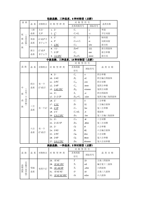
Pbma,Pmab, Pmca)
Pnmm(Pnmn, Pmnn)
Pmmn(Pmnm, Pnmm)Pbcn(Pcan,Pbna, Pcnb,Pnab, Pnca)
Pbca(Pcab)
Pnma(Pmnb, Pnam,
Pmcn,Pbnm, Pcmn)
Cmcm(Ccmm,Amma,
D2h6
D2h7
D2h8
D2h9
D2h10
D2h11
D2h12
D2h13
D2h14
D2h15
D2h16
D2h17
D2h18
D192h
D202h
D212h
D222h
D232h
D242h
D252h
D2h26
D2h27
D2h28
Pmmm
Pnnn
Pccm(Pbmb,Pmaa)
Pban(Pcna, Pncb)
Fd3m
Fd3c
Im3m
Ia3d
m3m
Oh
187
188
189
190
D3h1
D3h2
D3h3
D3h4
P-6m2
P-6c2
P-62m
P-62c
62m
D3h
191
192
193
194
D6h1
D6h2
D6h3
D6h4
P6/mmm
P6/mcc
P63/mcm
P63/mmc
6/mmm
D6h
I-43d
-43m
Td
183
184
185
186
C6v1
C6v2
C6v3
晶体对称性与空间群表
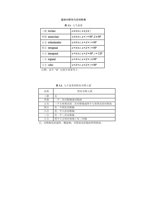
晶体对称性与空间群表表3.1.七个晶系三斜 triclinic a≠b ≠c; α≠β≠γ单斜 monoclinic a≠ b≠ c; α = γ = 90º,β≠ 90º正交 orthorhombic a≠b≠c; α= β = γ = 90º四方 tetragonal a = b≠c; α = β = γ = 90º六方 hexagonal a = b≠c;α = β = 90º, γ = 120º三方 trigonal a = b = c; α=β= γ≠ 90º立方 cubic a = b = c; α= β= γ= 90º注释:表中“≠”仅指不需要等于。
表3.2.七个晶系的特征对称元素晶系特征对称元素三斜无单斜一个二次对称轴或对称面正交三个互相垂直的二次对称轴或两个互相垂直的对称面四方有一个四次对称轴六方有一个六次对称轴三方有一个三次对称轴立方四个立方体对角线上有三次轴注:对称轴包括旋转、螺旋轴;对称面包括镜面和滑移面。
cP cFcI图3.5.14种Bravais晶格。
aP = 三斜(triclinic), mP = 简单单斜(monoclinic primitive), mC = 底心单斜(monoclinic C-centered),oP = 简单正交(orthorombic primitive),oC = C 底心正交(orthorombic C-centered,取轴方法不同,可以相当于A心底),oI = 体心正交(orthorombic body-centered),oF = 面心正交(orthorombic face-centered),tP = 简单四方(tetragonal primitive),tI = 体心四方(tetragonal body-centered),hP = 简单三方或六方(trigonal or hexagonal primitive),hR = 菱面体、按六方取晶胞(Rhombohedral hexagonal setting),cP = 简单立方(cubic primitive),cI = 体心立方(cubic body-centered),cF = 面心立方(cubic face-centered)。
APD-240G120资料

Document Number: 37016Revision 05-Dec-00 2元器件交易网Document Number: 91000Revision: 18-Jul-081DisclaimerLegal Disclaimer NoticeVishayAll product specifications and data are subject to change without notice.Vishay Intertechnology, Inc., its affiliates, agents, and employees, and all persons acting on its or their behalf (collectively, “Vishay”), disclaim any and all liability for any errors, inaccuracies or incompleteness contained herein or in any other disclosure relating to any product.Vishay disclaims any and all liability arising out of the use or application of any product described herein or of any information provided herein to the maximum extent permitted by law. The product specifications do not expand or otherwise modify Vishay’s terms and conditions of purchase, including but not limited to the warranty expressed therein, which apply to these products.No license, express or implied, by estoppel or otherwise, to any intellectual property rights is granted by this document or by any conduct of Vishay.The products shown herein are not designed for use in medical, life-saving, or life-sustaining applications unless otherwise expressly indicated. Customers using or selling Vishay products not expressly indicated for use in such applications do so entirely at their own risk and agree to fully indemnify Vishay for any damages arising or resulting from such use or sale. Please contact authorized Vishay personnel to obtain written terms and conditions regarding products designed for such applications.Product names and markings noted herein may be trademarks of their respective owners.元器件交易网。
空间群
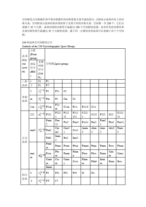
空间群是点对称操作和平移对称操作的对称要素全部可能的组合。
点群表示晶体外形上的对称关系,空间群表示晶体结构内部的原子及离子间的对称关系。
空间群一共230个,它们分别属于32个点群。
晶体结构的对称性不能超出230个空间群的范围,而其外形的对称性和宏观对称性则不能越出32个点群的范围。
属于同一点群的各种晶体可以隶属于若干个空间群。
230种晶体学空间群的记号Symbols of the 230 Crystallographic Space Groups晶系(Cry stal syste m) 点群(Pointgroup)空间群(Space group) 国际符号(HM)圣佛利斯符号(Schfl.)三斜晶系1 C1 P1Ci P单斜晶系2 P2 P21 C2m Pm Pc Cm Cc2/m P2/mP21/mC2/m P2/c P21/C C2/c正交晶系222 P222P2221P21212P212121C2221C222 F222 I222I212121 mm2Pmm2Pmc21Pcc2 Pma2 Pca21 Pnc2Pmn21Pba2 Pna21 Pnn2Cmm2Cmc21Ccc2Amm2Abm2Ama2Aba2 Fmm2 Fdd2Imm2Iba2 Ima2mmmPmmmPnnn Pccm Pban Pmma Pnna Pmna Pcca Pbam PccnPbcmPnnmPmmnPbcn Pbca PnmaCmcmCmca CmmmCccmCmmaCccaFmmmFdddImmmIbam Ibca Imma四方晶系4 P4 P41 P42 P43 I4 I41P I4/m P4/m P42/mP4/n P42/n I4/m I41/a422 P422P4212P4122P41212P4222P42212P4322P43212I422 I41224mm P4mmP4bmP42cmP42nmP4cc P4ncP42mcP42bcI4mm I4cmI41mdI41cd2m P2mP2cP21mP21cPm2Pc2Pb2Pn2Im2 I c2I2mI2d4/m mm P4/mmmP4/mccP4/nbmP4/nncP4/mbmP4/mncP4/nmmP4/nccP42/mmc P42/mcmP42/nbcP42/nnmP42/mbcP42/mnmP42/nmcP42/ncmI4/mmmI4/mcmI41/amdI41/acd三方晶系3 P3 P31 P32 R3P R32 P312 P321 P3112P3121P3212P3221R32 3m P3m1P31mP3c1 P31c R3m R3cmP1mP1cPm1P c1RmR c六方晶系6 P6 P61 P65 P62 P64 P63P6/m P6/mP63/m622 P622P6122P6522P6222P6422P63226mmP6mmP6ccP63cmP63mcm2Pm2Pc2P2mP2c6/mmmP6/mmmP6/mccP63/mcmP63/mmc立方23 P23 F23 I23 P213 I213晶系m Pm3 Pn3 Fm3 Fd3 Im3 Pa3 Ia3432 P432 P4232F432F4132I432P4332P4132I41323m P3mF3mI3m P3nF3cI3dm m PmmPnnPmnPnmFmmFmcFdmFdcImm Ia d1 三斜晶系(Triclinic)点群空间群对称要素方位关系1 1 (1) P12 -1 (2) P-12 单斜晶系(Monoclinic) b为唯一轴点群空间群对称要素方位关系3 2 (3) P2(4) P21(5) C2b为2次轴或21螺旋轴4 m (6) Pm(7) Pc(8) Cm(9) Cc b为⊥m5 2/m (10) P2/m(11) P21/m(12) C2/m(13) P2/c(14) P21/c(15) C2/c b为2+⊥m3 斜方晶系(Orthohombic) 三个方位:a,b,c点群空间群对称要素方位关系6 222 (16) P222(17) P2221(18) P21212(19) P212121(20) C2221(21) C222(22) F222(23) I222(24) I212121 abc皆为27 mm(mm2)(26) Pmc21 (27) Pcc2 (28) Pma2 (29) Pca21 (30) Pnc2 (31) Pmn21 (32) Pba2 (33) Pna21 (34) Pnn2 (35) Cmm2 (36) Cmc21(37) Ccc2 (38) Amm2 (39) Abm2 (40) Ama2 (41) Aba2 (42) Fmm2 (43) Fdd2 (44) Imm2 (45) Iba2 (46) Ima2a 为⊥m ,b 为⊥m ,c 为2(两两垂直的对称面交线为2)。
- 1、下载文档前请自行甄别文档内容的完整性,平台不提供额外的编辑、内容补充、找答案等附加服务。
- 2、"仅部分预览"的文档,不可在线预览部分如存在完整性等问题,可反馈申请退款(可完整预览的文档不适用该条件!)。
- 3、如文档侵犯您的权益,请联系客服反馈,我们会尽快为您处理(人工客服工作时间:9:00-18:30)。
60PPR 96PPR 150PPR 180PPR 200PPR 240PPR 250PPR 256PPR 270PPR 300PPR 360PPR 480PPR 500PPR 512PPR
120PPR 192PPR 300PPR 360PPR 400PPR 480PPR 500PPR 512PPR 540PPR 600PPR 720PPR 960PPR 1000PPR 1024PPR
One Encoder Can Provide Over 20 Model Variations...
Select Pulse Width Select PPR’s
Select Channels
SW1
SW2
SW3
SW4
SW5 on bottom
Simply remove the bottom panel and set the switches for the functions desired.
P 4 or 6 X X X — A X
Shaft Diameter Order Choice 1=1/4" diameter 2=5/16" diameter 3=3/8" diameter 4=1/2" diameter Shaft Extension Order Choice 1=Single extension 2=Double extension Mounting Type Order Choice 1=2.0" B.H.C. 2=Flanged base (mounting type can be changed by substituting bottom plate when programming) Channel Types Are: Q=Quadrature outputs* P=Separate UP & DOWN output channels U=Pulse train output with UP/DN direction output S=Single output channel Channel Types Programming Channel Outputs Order Choice A=NPN w/pullup res. B=NPN open collector F=5V NPN w/pullup res. G=5V NPN open collector H=PNP outputs K=5V line driver L=8-15V line driver Type SW3 Q S CCW CCW P Cntr U S CW CW Cntr SW4
0600
Encoders to be shipped with the PPR as ordered & quadrature channel type with 50/50 duty cycle pulse. *Quadrature available for 1st three SW 1 & 2 columns (below).
元器件交易网
Hercules Encoders
Programmable
Incremental Encoders
Select PPR’s Choice of 5 PPR’s Select Pulse Width 10µSecs, 30µSecs or Square Wave Select Channels •Single or quadrature channels •Count with up/down direction •Up count channel and down count channel Function Selection Switches SW1 SW2 SW3 SW4 SW5 on bottom
H e r c u l e s
6000 Series
4000 Series
For the latest specifications visit our website
元器件交易网
Hercules Encoders “Value Added” Programmable Encoder
6
Series 4000 and 6000 Programmable Encoders
Standard Features • 4000 Series - Space-Saving Enclosure, 1-1/2"D x 3"H x 3"W, 25 to 4096 PPR. • 6000 Series - Internal Space for 3 Separate Encoders, 25 to 4096 PPR. • Built-In Anti-Jitter Circuitry. • Operating Voltage Flexibility - 8 to 28Vdc, 5Vdc with TTL Outputs and Line Drivers, etc. • Low Supply Current Requirements - Only 50 Milliamperes per Encoder • Extra Heavy Duty 1/2"D Shafts - Optional
240PPR 384PPR 600PPR 720PPR 800PPR 960PPR 1000PPR 1024PPR 1080PPR 1200PPR 1440PPR 1920PPR 2000PPR 2048PPR
7
Programming of Switches: \CCW=set to left; | Cntr=set center; /CW=set to right Note: for SW5 (right hand column PPR x 4) Time Settings: CW=other columns; Cntr=5-10µsec; CCW=25-35µsec
Switch Positions Order PPR’s Model PPR’s Available With This Model
SW1 SW2 SW1 SW2 SW1 SW2 SW1 SW2
SW1
SW2
SW5
CCW
120 192 300 360 400 480 500 512 540 600 720 960 1000 1024 30, 60, 120, 240, 480 48, 96, 192, 384, 768 75, 150, 300, 600, 1200 90, 180, 360, 720, 1440 100, 200, 400, 800, 1600 120, 240, 480, 960, 1920 125, 250, 500, 1000, 2000 128, 256, 512, 1024, 2048 135, 270, 540, 1080, 2160 150, 300, 600, 1200, 2400 180, 360, 720, 1440, 2880 240, 480, 960, 1920, 3840 250, 500, 1000, 2000, 4000 256, 512, 1024, 2048, 4096
CCW
CntrCCWCW源自CCWCWCntr
CW
CW
480PPR 768PPR 1200PPR 1440PPR 1600PPR 1920PPR 2000PPR 2048PPR 2160PPR 2400PPR 2880PPR 3840PPR 4000PPR 4096PPR
CCW
30PPR 48PPR 75PPR 90PPR 100PPR 120PPR 125PPR 128PPR 135PPR 150PPR 180PPR 240PPR 250PPR 256PPR
