多功能电源
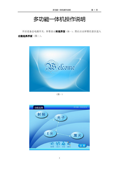
多功能一体机电源操作说明11080
2.修改治疗参数:
点击需要修改的治疗参数后原治疗模式显示区域会弹出修改治疗参数所需的数字键盘,通过键盘直接输入所需的治疗参数后点击确定按钮参数修改完毕,若点击的是取消按钮被修改参数将返回到修改前的值。
光头状态:
图标 表示光头已点亮;图标 表示光头未点亮;光头被点亮后,才可进入充电状态,如五秒钟未点亮光头,则返回待机状态。
充电状态:
图标 表示充电成功; 充电未成功,充电成功后系统才能进入治疗状态,可以进行治疗。,如五秒钟充电未成功,则返回待机状态。
E光脉冲输出示意图
激光:
在功能选择界面选择激光后会进入激光治疗模式选择界面(图十一),激光治疗模式选择界面提供了6种针对人体不同部位的治疗模式供用户选择。当治疗完毕后从激光治疗界面(图十二)返回激光治疗模式选择界面时,系统会自动将治疗参数:激光能量和出光频率等保存在所选的治疗模式中,在下次选用此模式时系统会自动调用此模式中保存的治疗参数。
4.调节光子输出能量
光子输出能量调节范围1-50J/cm2,通过上下箭头调节其大小,若一直按着调节按钮,光子能量会自动增加或减小,能量调节步长为1,数字越大,光子输出能量越大,可根据实际情况调节。
5.调节射频输出能量
射频能量调节范围为:1-20,通过上下箭头调节其大小,若一直按着调节按钮,射频能量会自动增加或减小,能量调节步长为:1数字越大,射频输出能量越大,可根据实际情况调节。
(图五)
(图六)
进入光子治疗界面等待3秒左右之后按工作键使其变为橘黄色,此时按治疗头上的工作按钮就会有脉冲光输出,屏幕上同时会显示 ,表示此时正在输出脉冲光, 表示此时无脉冲光输出。治疗完毕后按停止键,系统会自动给当前计数器清零,此时按退出键将返回到光子治疗模式选择界面。
SPS2000太阳能车载多功能电源说明

SPS2000太阳能车载多功能电源说明本产品可用于启动汽车、卡车、游艇以及小型娱乐车,其内置空气压缩机可用于充气式轮胎、小型的运动或野营设备等。
本系统也广泛用于直流电产品,是理想的应急电源。
SPS2000同时还内置有应急灯、充电器并配有交、直流充电连接线及大电流启动电缆。
功能描述:平时显示器处于省电状态以降低功耗,当按下功能鍵(FUNCTION)时显示器打开;连续多次按功能键则在电量百分比(CHARGE)、气压值(PRESSURE)与逆变功率(WATTS)之间循环切换,相应的状态指示灯(用于指示显示器处于何种状态)亮。
若逆变器与打气泵均未打开,且三个按钮连续两分钟无操作,显示器则自动关闭。
气压设定功能:在气压显示状态下,直接按上(PSI UP)、下(PSI DOWN)即可进行气压值设定。
若连续按住UP键加到260PSI时系统会从零重新开始往上加;按住DOWN键往下减,减到OPSI时系统会从260PSI重新开始往下减;循环加减。
在气压设定过程中,状态指示灯闪烁。
设定好以后,按功能键或气泵开关退出设定状态,此时值被保存,指示灯转为常亮。
若在两分钟后没有按指定方式退出,则系统会自动退出并保存设置。
退出后的显示状态取决于先前的显示状态。
在省电状态下,若逆变器或打气泵被打开时,显示器将自动开启并进入相对应的显示状态同时对应的状态指示灯点亮。
若气泵与逆品同时被打开,则优先显示气压值。
按功能键可在其它状态间进行切换。
若要关闭显示器,须按住功能键至少2秒,系统返回到省电状态。
打气泵工作期间,将不允许关闭显示器,同时也不允许进入到气压设定状态,此时若按住PSI UP或PSI DOWN则显示预先设定的气压值,并且气压显示状态灯熄灭,而不进入设定状态,松开按键回到实时气压显示状态,气压显示状态灯亮。
当加气到达预先设定的气压值时自动关断打气泵。
另外,在打气泵工作过程中,只要气压值超过260PSI则自动关闭打气泵。
按功能键(FUNCTION)切换到CHARGE状态。
多功能电源模块及模块化结构
多功能电源模块及模块化结构1.引言1.1 概述在本文中,我们将探讨多功能电源模块及其模块化结构。
电源模块是电路系统中至关重要的组成部分,它提供所需的电能以支持其他电子设备的正常运行。
随着科技的不断发展,对电源模块的要求也越来越高,需要具备更多的功能和灵活性。
多功能电源模块是一种集成了多种功能的电源设备。
传统的电源模块主要提供基本的电能转换功能,例如从交流电源转换为直流电源,并通过稳压电路保持电流稳定。
然而,现代的电子设备对电源的需求越来越复杂,需要满足不同的电压和功率要求,并提供更多的保护功能,例如过电压保护和短路保护。
多功能电源模块能够同时满足这些需求,并且还可以根据具体的应用场景进行配置和调整。
为了提高电源模块的可维护性和可扩展性,模块化结构被广泛采用。
通过将电源模块划分为多个独立的模块,每个模块负责不同的功能,例如输入电路、输出电路和保护电路等,可以更方便地进行组装和维修。
此外,模块化结构还可以实现功能的灵活组合,根据实际需求进行自定义配置。
本文将对多功能电源模块及其模块化结构进行详细分析和探讨。
首先,我们将介绍多功能电源模块的基本功能和要求。
然后,我们将讨论电源模块的模块化结构,包括各个模块的功能和相互之间的关系。
最后,我们将总结本文的内容,并展望多功能电源模块未来的发展方向。
希望通过本文的阐述,读者能够更深入地了解多功能电源模块及其模块化结构,为电源设备的设计和应用提供参考和借鉴。
让我们一起开始探索吧!文章结构部分的内容可以如下所示:1.2 文章结构本文共分为三个主要部分,分别是引言、正文和结论。
引言部分(Chapter 1)介绍了本文的背景和目的。
首先,我们对多功能电源模块及其模块化结构进行了概述,包括其定义和重要性。
其次,我们阐述了本文的结构和布局,以便读者更好地理解文章的内容和章节的组织。
最后,我们明确了本文的目的,即为读者提供一个全面而深入的了解多功能电源模块及其模块化结构的指南。
PACSystems RX3i IC695PSD140 多功能DC电源说明书

PACSystems* RX3iIC695PSD140 GFK-2377C Multipurpose DC Power Supply, 40 Watts September 2011PACSytems* RX3i Power Supply IC695PSD140 is a multipurpose 40-Watt supply that Array operates from an input voltage source in the range of 18 VDC to 30 VDC.This power supply provides three outputs:▪+5.1 VDC output,▪+24 VDC relay output that can be used to power circuits on Output Relay modules.▪+3.3 VDC. This output is used internally by RX3i modules with IC695 catalog numbers.Multipurpose Power Supply IC695PSD140 is suitable for use in load-sharing andredundancy application. It must be installed in a PACsystems RX3i (IC695 catalog number)Universal Backplane. It can be used as the only power supply in the backplane, orcombined with up to three additional Multipurpose Power Supplies.This Power Supply cannot be used with RX3i IC695PSD040 or IC695PSA040 PowerSupplies in redundant or increased capacity modes. Damage to equipment mayresult.Load SharingWhen RX3i Multipurpose DC Power Supplies are combined into load-sharing applications,following the installation guidelines given in this datasheet, they must be wired to the samepower source in such a way that they all can be powered up or powered downsimultaneously. The On/Off front panel switch on each of the power supplies must be left inthe On position.In a load-sharing application, it is important to ensure that the load-sharing powersupply modules’ On/Off switches cannot be inadventently used. The minimumnumber of power supplies needed to meet the system power requirements MUSThave their switches always kept in the On position. Also, the load-sharing powersupplies must be connected to the system power source through the same externalswitch. The system must be powered up and powered down only from the externalswitch. If individual power supplies are powered up or powered down using theirOn/Off switches or separate external switches, resulting in insufficient powercapacity, equipment damage may result. It may be necessary to re-load the PLCoperating system to resume operation.*indicates a trademark of GE Intelligent Platforms, Inc. and/or its affiliates. All other trademarks are the property of their respective owners. All rights reserved.GFK-2377CInstallation Information for Hazardous LocationsImportant Product InformationGFK-2377CFour LEDs on the Power Supply indicate:▪Power (Green/Amber). When this LED is green, it indicates power isbeing supplied to the backplane. When this LED is amber, power isapplied to the Power Supply but the Power Supply switch is off.▪P/S Fault (Red). When this LED is lit, it indicates the Power Supplyhas failed and is no longer supplying sufficient voltage to thebackplane.▪Over Temperature (Amber). When this LED is lit, it indicates thePower Supply is near or exceeding its maximum operatingtemperature.▪Overload (Amber). When this LED is lit, it indicates the PowerSupply is near or exceeding its maximum output capability on atleast one of its outputs.If the red P/S FAULT LED is lit, the Power Supply has failed and is nolonger supplying sufficient voltage to the backplane .The amber OVERTEMP and OVERLOAD LEDs light to warn of hightemperature or high load conditions.The CPU Fault Table shows a fault if any Overtemperature, Overload, orP/S Fault occurs.Wiring TerminalsTerminals for +24V and –24V power, ground, and MOV disconnectaccept individual 14 to 22AWG wires.On/Off SwitchThe ON/OFF switch is located behind the door on the front of themodule. The switch controls the operation of the outputs of the supply. Itdoes NOT interrupt line power. A projecting tab next to the switch helpsprevent accidentally turning it on or off.GFK-2377CSpecifications: IC695PSD140* The Inrush Current specification is given as a guide for sizing the external power source for the IC695PSD140. Peak inrush current may be higher for shorter durations.Overcurrent ProtectionThe 5.1 VDC output is electronically limited to 7 Amps. The 3.3 VDC output is limited to 10 Amps. If an overload (including short circuits) occurs, it is sensed internally and the Power Supply shuts down. Because it is designed for redundancyapplications, this Power Supply latches “OFF” in fault conditions and will not automatically try to restart. Input power must be cycled to clear a latched fault. However, if the Power Supply is used in a non-redundant application where automatic restarting is required, a jumper plug can be installed as shown below.An internal non-repairable fusible link in the input line is provided as a backup. The Power Supply usually shuts down before the fusible link blows. The fusible link also protects against internal supply faults. The CPU Fault Table shows a fault if any Overtemperature, Overload, or P/S Fault occurs. There is no additional indication if the Power Supply fusible link blows.In a non-redundancy application, where automatic restarting may beappropriate, a shunt can be installed on back of the module as shown at left. The shunt must have 0.100 inch spacing on center and accommodate 0.25 inch pins. Example parts are Radio Shack DIP Programming Shunt#276-1512 and DIGI-Key #59000-ND. The module must be removed from the backplane to install the shunt.GFK-2377CThermal Deratings: PSD140The maximum output power for Power Supply PSD140 depends on the ambient temperature, as shown below. Full output power is available up to at least 40°C (89.6°F).45 40 35 30 25 20 15 10 5 0102030 40 5060Temperature (C)P o w e r (W )Total28 Volts 30 Volts5.1 Volt Fully-Loaded45 40 35 30 25 20 15 10 5 0102030 40 50 60Temperature (C)P o w e r (W )3.3 Volt Fully LoadedGFK-2377CField Wiring: IC695PSD140Power Source and Ground ConnectionsThe wires from the power source and ground connect to the terminals on the Power Supply as shown at right. Each terminal accepts one AWG 14 to AWG 22 wire. When tightening the screw terminals, do not exceed the maximum torque limit of 0.5 N-m (4.4 inch-lbs).If the same external DC power source is used to provide power to two or more power supplies in the system, connection polarity must beidentical at each RX3i power supply. A resulting difference in potential can injure personnel or cause damage to equipment. Also, each backplane must be connected to a common system ground.Input Overvoltage ProtectionThe bottom terminal is normally connected to frame ground with a user-installed jumper as shown at lower right. If overvoltage protection is not required or is supplied upstream, no jumper is required.To Hi-pot test this supply, overvoltage protection must be disabled during the test by removing the jumper. Re-enable overvoltage protection after testing by reinstalling the jumper.This power supply is not isolated and is therefore not compatible with floating or positive grounded systems.Power Supply Field WiringTerminalsEach terminal accepts one AWG 14 to AWG 22 wire. The end of each wire should be stripped at least 9mm (3/8-inch). The terminal can accept a wire that is stripped up to 11 mm (0.433 in) while providing full seating of the insulator. The wire must be fully inserted as shown at left, so that the insulation meets the insulation stop position inside the terminal. Tightening the terminal screw pivots the clamp firmly against the stripped end of the wire, holding it in place. If the wire is not fully inserted as shown at right, tightening the terminal screw may push the wire upward so that it is not connected.GFK-2377CConnections for Load SharingIn load-sharing stallations, additional Multipurpose Power Supplies above the minimum required for the system load may be wired to the same power source, or a different source.Extra Power Supply Optionally Connected toDifferent SourceExample: Power Supplies Needed to Meet Load RequreementsConnections for Power Supply RedundancyPower Supply redundancy can be provided by using one additional Multipurpose Power Supply above the minimum required for the system power load. In this type of installation, all Multipurpose Power Supplies contribute a share of the backplane power and run at a correspondingly reduced load. This results in longer life for the individual power supplies. In addition, should one power supply module fail, system operation is not interrupted. The front panel switch can be used to remove a redundant unit. Note that this type of system does not provide protection against loss of the input power source. If more than power supply is switched off, the remaining power supplies may become overloaded and shut down. An External switching device must be used to remove power from more than 1 power supply at a time in the Power Supply Reduncancy mode.This Extra Power Supply Provides Power Supply Module RedundancyExample: Three Power SuppliesNeeded to Meet Load RequirementsPower Source RedundancyIf the overall power needs of the system can be met using either one or two Multipurpose Power Supplies, then power source redundancy can be provided. This requires using twice the minimum number of Multipurpose Power Supplies required tomeed the system load requirements. In this type of system, half of the Multipurpose Power Supplies must be connected to onepower source and the other half must be connected to a separate source. This arrangement provides all the advantage of a Basic Redundancy system, as described above, plus power source redundancy. The front panel switch may be used to remove an individual power supply as long as the minimum number of units remain powered up.Two Extra Load-Sharing Power Supplies Provide Power Source RedundancyExample: Two Load-Sharing Power SuppliesNeeded to Meet Load Requreements。
DC-400_CN

DC-400400A直流多功能焊接电源林肯电气公司制造的高负荷、工业用的多功能电源广泛应用于MIG焊接、药芯焊丝焊接、埋弧焊、手工焊以及直流氩弧焊工艺并得到一致好评,同时这种机器也是碳弧气刨工艺极好的选择。
其广泛的适用性并不意味着复杂-DC -400装配和使用非常容易。
使用了工厂安装或现场安装的多功能开关,只要简单地旋转开关即可实现工艺之间的转换。
配备的电流表及电压表使得关键焊接参数的监控非常容易。
而电感和电弧吹力控制使操作者能根据具体情况得到最佳的电弧。
工艺:手工焊 氩弧焊 气体保护焊 药芯焊丝焊 埋弧焊碳弧气刨• 下降特性(手工焊/氩弧焊/碳弧气刨)与平特性(气体保 护焊/药芯焊丝焊)和平特性埋弧焊接模式之间能够方便 地进行转换。
• 在下降特性(手工焊/氩弧焊)模式时电弧吹力控制调节 短路电流以产生柔软的或坚挺的电弧。
• 电弧控制调节能改变气保焊/药芯焊丝焊时电弧的夹断力 从而控制飞溅、熔池流动性和焊缝成形。
• 能用于手工焊、直流氩弧焊以及最大可达8mm碳棒的碳 弧气刨。
• 固态电路为重复的焊接应用提供超长的使用寿命。
• 全范围输出控制电位器提供出色的焊接性能。
• 电流表/电压表为标准配件。
• ±10%网路电压补偿维持焊缝的一致性。
•低矮的外壳能将三台机器叠起以节省占地面积。
(选用 小车时不推荐叠放)• 风扇冷却寿命更长。
具有电流过载的电保护和温度过高 的热保护。
• 经过处理的线圈及整流器能防潮湿及腐蚀环境。
• 14芯MS型航空接头电缆连接件和接线端子能连接遥控装 置和送丝机,焊接电缆为螺栓连接。
• 短路保护器保护送丝机电源:接线端子上的115V,14芯 插座上的42V和115V。
• K1309型号具有能连接水冷器的220V,2A交流辅助电源 插座。
• 带指示灯的115V交流电源启动开关提供额外安全保障。
• 耐久的粉末喷漆系统保护所有的喷漆表面以延长机器的 寿命。
• 保修期内免费维修。
多功能电源检测仪用法
多功能电源检测仪是一种用于测试和监测电源参数的设备,可以提供电压、电流、功率等多项数据的测量和分析。
以下是多功能电源检测仪的一般用法:
连接电源:将多功能电源检测仪的电源输入端连接到待测试的电源输出端,确保连接稳固。
设置参数:根据需要,设置多功能电源检测仪的测量范围、单位和精度等参数。
可以通过操作面板、按键或者电脑软件进行设置。
测量电压:选择所需的电压测量范围,将检测仪的电压探头与待测试电源的电压输出端连接。
测量仪将显示电源的实时电压数值。
测量电流:选择所需的电流测量范围,将检测仪的电流探头与待测试电源的电流输出端连接。
测量仪将显示电源的实时电流数值。
测量功率:根据需要选择功率测量模式,将检测仪的功率探头与待测试电源的负载端连接。
测量仪将显示电源的实时功率数值。
数据分析:多功能电源检测仪通常具备数据记录和分析功能。
可以记录并保存测量数据,以便后续分析和比较。
故障诊断:多功能电源检测仪还可以用于故障诊断和性能评估。
通过对电源参数的监测和分析,可以及时发现电源问题并进行相应的修复。
请注意,在使用多功能电源检测仪时,应仔细阅读和遵守设备的使用说明和安全注意事项。
确保正确操作和保护设备以及自身安全。
多功能电子仪表电源设计

第 9卷 第 4期 2 1 年 8月 01
实验科 学与技术
E p rme tS i n e a d T c n lg x e i n ce c n e h oo y
V 1 9 No 4 o. . Au u t2 g s. 01 1
多 功 能 电子 仪 表 电源 设 计
多个 不 同 电 源 ,而 供 电 常 常 要 求 用 3—9 的 干 电 V 池 。因此 ,将 9 V 的 电平 转 化 为 41 -2 V、 +5V、 以及 ± . 3 3V的 电压在实 际应 用 中将会 有 很 大 的应
M 30 3 C 4 6 来实现 电源系统设计 要求。当输 人 电压 为 1 8V左 右 时 ,L 7 1 M 82可 以稳 定 输 出 +l 电 2V 压。但是 由于系统要 求选择 的基 准 电压 为 + , 9 V 所 以不满 足其 输入 要求 ,如 果采 用 降压 电路进 行 变 化来 实 现 ,转 换 电路 较 为 复 杂 。MC 46 30 3是 一 块
单 片 D / C变 换控 制 芯 片 ,内含 直 流 到 直 流 变换 CD 器所 要求 的 功 能 ,可 以实 现 一l 电 压 的 输 出 。 2V
但是其应用时对外围元件参数的要求过高,很难进 行匹配 ,同时会增加维护难度 J 。 () 2 采用升压式变换器 M X 3 A 7 2和 IL6 2 C 76 来 实现。M X 3 是 C O A 72 M S直流 一 直流开关型升压稳 压器 ,通过对其外围电路的简单连接 ,并且输入电
多功能电源使用说明书

PDF 文件使用 "pdfFactory Pro" 试用版本创建
33、熔断器: 规格:2A 保险管 用途:保护低压电源 34、直流电流表: 规格:0~30V 用途:指示Ⅰ组电源输出电压 35、直流电流表: 规格:0~2A 用途:指示Ⅰ组电源输出电流 36、Ⅰ组电源输出电压调节旋钮 37、Ⅰ组电源输出电流调节旋钮 38、发光管: 规格:Φ5 红色发光二极管 用途:Ⅰ组电源稳压指示 39、发光管: 规格:Φ5 红色发光二极管 用途:Ⅰ组电源稳流指示 40、自锁紧接线柱: 用途:二只接线柱组成Ⅰ组电源输出插口 41、直流电压表: 规格:0~30V 用途:指示Ⅳ组电源输出电压 42、直流电流表: 规格:0~2A 用途:指示Ⅳ组电源输出电流 43、Ⅳ组电源电压调节旋钮 44、Ⅳ组电源电流调节旋钮 45、发光管: 规格:Φ5 红色发光二极管
四、结构
A、实验桌 实验桌系木材加工而成,二个抽屉,一个实验单元柜,一个元件库组成。
B、电源及信号源箱体 1、箱体: 规格:136cm×21cm×30cm 材料:工程塑料 2、面板: 规格:135cm×27cm 材料:铝塑板 3、三相螺旋熔断器: 规格:额定电流 15A 用途:整个实验台上第一保护装置 4、指示灯: 规格:220V 氖泡指示灯 用途:用作电源输入的指示,表示外加三相四线制电源已和实验台接通。 5、指示灯:3 只 规格:220V 氖泡指示灯 用途:用以电源输出的指示,表示实验台的三相四线制电源已有输出。
8
PDF 文件使用 "pdfFactory Pro" 试用版本创建
57、电压调节旋钮: 用途:用以调节要调交流电源的输出端口 58、自锁紧接线柱: 用途:作为可调交流电源的交流输出端口 59、自锁紧接线柱: 用途:作为可调交流电源脉动直流部分的交流输入端口 60、自锁紧接线柱: 用途:作为可调交流电源的脉动直流输出端口 61、按钮: 用途:按下此钮,其上方数码管显示 5V、3-24V 交流,0-240V 可调交直流电源的过 流次数。 62、数码管: 用途:如 62 所述。 63、按钮: 用途:当 5V、3-24V 交流、0-240V 可调交直流电源因过流而被保护时,消除过流后, 按此钮时,电源恢复正常。 64、键盘锁: 用途:打开此锁,当 5V、3-24V 交流、0-240V 可调交直流三种电源因过流而被保护 时,才记录并显示过流次数。
多功能正负直流电源的设计
中北大学课程设计任务书2010/2011 学年第一学期学院:信息与通信工程学院专业:电子信息科学与技术学生姓名:杨建军学号:0805014117 课程设计题目:多功能正负直流电源的设计起迄日期:12月26日~1月7日课程设计地点:中北大学指导教师:程耀瑜,李文强系主任:程耀瑜下达任务书日期: 2010 年 12 月 26 日目录设计目的 (1)实验设计任务 (1)设计电路原理和原理图 (1)对整个电源各功能的仿真测试结果 (5)设计总结 (7)参考文献 (8)附录 (9)多功能正负直流稳压电源实验报告一.设计目的:主要针对模拟电子技术和数字电子技术课程要求,培养学生进行实用电路设计、仿真、安装、调试等多个环节的综合能力,同时培养学生用课程中所学的理论独立地解决实际问题的能力。
另外要求每个学生独立完成一个选题的设计任务。
二.实验设计任务(1)掌握桥式整流电容滤波电路的工作原理;(2)掌握稳压三极管的选型;(3)掌握正直流电源(+5V, +3.3V, +24V)电路的设计、仿真与调试;(4)掌握负直流电源(-12V)电路的设计、仿真与调试;(5)掌握方案设计与论证;(6)掌握用相关软件进行电路图设计、仿真,以及对仿真结果的分析、总结。
三.设计电路原理和原理图稳压直流电源是由变压器、整流电路、滤波电路、稳压电路组成在本实验中我们采用了桥式整流器电路来实现电流的整流,其输出电压和输入电压的有效值之间关系为:U0=0.9U2。
我们采用可调式三端稳压管LM317、固定式三端稳压管LM78系列、LM79系列来实现3.3V、5V、24V、-12V的多选择电源电压。
LM317的原理如下:稳压电源的输出电压可用下式计算,Vo=1.25(1+R2/R1)。
仅仅从公式本身看,R1、R2的电阻值可以随意设定。
然而作为稳压电源的输出电压计算公式,R1和R2的阻值是不能随意设定的。
317稳压块的输出电压变化范围是Vo=1.25V—37V。
兄弟牌MFC7420多功能一体机开关电源
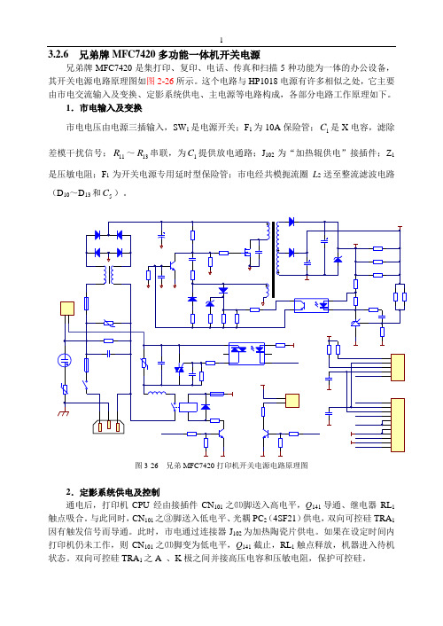
3.2.6 兄弟牌MFC7420多功能一体机开关电源 兄弟牌MFC7420是集打印、复印、电话、传真和扫描5种功能为一体的办公设备,其开关电源电路原理图如图2-26所示。
这个电路与HP1018电源有许多相似之处,它主要由市电交流输入及变换、定影系统供电、主电源等电路构成,各部分电路工作原理如下。
1.市电输入及变换 市电电压由电源三插输入,SW 1是电源开关;F 1为10A 保险管;1C 是X 电容,滤除差模干扰信号;11R ~13R 串联,为1C 提供放电通路;J 102为“加热辊供电”接插件;Z 1是压敏电阻;F 1为开关电源专用延时型保险管;市电经共模扼流圈L 2送至整流滤波电路(D 10~D 13和5C )。
2.定影系统供电及控制通电后,打印机CPU 经由接插件CN 101之⑾脚送入高电平,Q 141导通、继电器RL 1触点吸合。
与此同时,CN 101之③脚送入低电平、光耦PC 2(4SF21)供电,双向可控硅TRA 1因有触发信号而导通。
此时,市电通过连接器J 102为加热陶瓷片供电。
如果在设定时间内打印机仍未工作,则CN 101之⑾脚变为低电平,Q 141截止,RL 1触点释放,机器进入待机状态。
双向可控硅TRA 1之A 、K 极之间并接高压电容和压敏电阻,保护可控硅。
3.主电源该机采用了由开关管Q 1(K2717)和开关变压器T 1为核心构成的变压器耦合型自激式开关电源。
(1)功率管Q 1的开关过程输入整流滤波电压约300V ,一路经开关变压器T 1主绕组加到Q 1漏极(D );另一路经2R ~4R 送到Q 1栅极(G ),为Q 1提供启动电压。
刚上电时,Q 1栅极的电压是市电由2R ~4R 与15R 的分压,因后者远远小于前者,故Q 1栅极所加电压在MOSFET 安全工作范围之内。
T 1正反馈绕组与功率管组成开关振荡电路,Q 1既是开关管,又是振荡管。
(2)稳压控制次级侧,D 102与102C ,D 103与101C 整流滤波得到两组直流电压。
什么是多功能移动电源?

什么是多功能移动电源?
出门旅行的时候,手机、平板电脑等数码设备是必不可少的,能为行程带来很多的乐趣,可是设备自带电量较低却是一个很大的问题,如何在出游时也能保证为这些设备及时充电就成了一个必须要解决的问题,在出游时带上一个多功能移动电源就可以较好的解决充电问题:移动电源是一种集供电和充电功能于一体的便携式充电器,可以给手机等数码设备随时随地充电或待机供电。
一般由锂电芯或这干电池作为储电单元。
区别于产品内部配置的电池,也叫外挂电池。
一般配备多种电源转接头,通常具有大容量、多用途、体积小、寿命长和安全可靠等特点。
多功能移动电源指附加的功能:双USB充电功能、LED手电筒功能、无线VIFI的功能、紫外线验钞功能、飞行点烟器等等。
P500多功能应急移动电源使用说明书VS

使用说明书 / User Manual
PACK
多 功 能 移 动 电 源
POWER PACK
多 功 能 移 动 电 源
目录
1、产品介绍
2、功能件介绍
3、各功能注意事项
4、售后质保服务
非常感谢您购买深圳米阳科技有限公司的P 系列多功能应急移动电源.系列多功能应急移动电源是一个备用"电站",其重量轻、容量高、功率大,能为您提供方便的移动电源解决方案.广泛应用于移动式或野外办公室(医疗救护、消防救援等)、野外休闲、邮电通讯及公安抢险等地的户外应急电源、野外汽车应急启动引擎以及广泛停电区域等。
多功能350W AC到DC封闭切换电源说明书
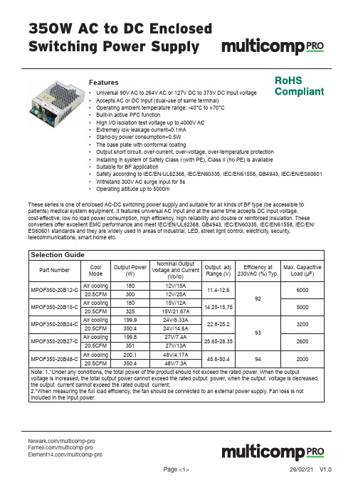
/multicomp-pro /multicomp-proFeatures• Universal 90V AC to 264V AC or 127V DC to 373V DC input voltage• Accepts AC or DC input (dual-use of same terminal)• Operating ambient temperature range: -40°C to +70°C• Built-in active PFC function• High I/O isolation test voltage up to 4000V AC• Extremely low leakage current˂0.1mA• Stand-by power consumption˂0.5W• The base plate with conformal coating• Output short circuit, over-current, over-voltage, over-temperature protection• Installing in system of Safety Class I (with PE), Class II (no PE) is available• Suitable for BF application• Safety according to IEC/EN/UL62368, IEC/EN60335, IEC/EN61558, GB4943, IEC/EN/ES60601• Withstand 300V AC surge input for 5s• Operating altitude up to 5000mThese series is one of enclosed AC-DC switching power supply and suitable for all kinds of BF type (be accessible to patients) medical system equipment. It features universal AC input and at the same time accepts DC input voltage, cost-effective, low no load power consumption, high efficiency, high reliability and double or reinforced insulation. These converters offer excellent EMC performance and meet IEC/EN/UL62368, GB4943, IEC/EN60335, IEC/EN61558, IEC/EN/ ES60601 standards and they are widely used in areas of industrial, LED, street light control, electricity, security, telecommunications, smart home etc.Selection GuidePart Number Cool ModeOutput Power(W)Nominal Output Voltage and Current (Vo/Io)Output adj. Range (V)Efficiency at230VAC (%) Typ.Max. CapacitiveLoad (µF)MPOF350-20B12-C Air cooling18012V/15A11.4-12.6926000 20.5CFM30012V/25AMPOF350-20B15-C Air cooling18015V/12A14.25-15.755000 20.5CFM32515V/21.67AMPOF350-20B24-C Air cooling199.924V/8.33A22.8-25.2933200 20.5CFM350.424V/14.6AMPOF350-20B27-C Air cooling199.827V/7.4A25.65-28.352600 20.5CFM35127V/13AMPOF350-20B48-C Air cooling200.148V/4.17A45.6-50.4942000 20.5CFM350.448V/7.3ANote: 1.*Under any conditions, the total power of the product should not exceed the rated power. When the output voltage is increased, the total output power cannot exceed the rated output power, when the output voltage is decreased, the output current cannot exceed the rated output current;2.*When measuring the full load efficiency, the fan should be connected to an external power supply. Fan loss is not included in the input power./multicomp-pro /multicomp-proOutput SpecificationsItemOperating ConditionsMin.Typ.Max.UnitOutput Voltage Accuracy*Full load range 12V/15V --±3----24V/27V/48V--±2--Line Regulation Rated load --±0.5--Load Regulation0% - 100% load--±1--Output Ripple & Noise*20MHz bandwidth (peak-to-peak value)12V----120mV 15V ----12024V ----15027V ----20048V----250Temperature Coefficient --±0.03--%/°C Minimum Load 0----%Hold-up Time230VAC, full loadAir cooling 1214--ms 20.5CFM 68Stand-by Power Consumption ----0.5W Short Circuit Protection recover time <5s after the short circuit disappear Hiccup, continuous, self-recoverOver-current Protection≥110%, self-recover Over-voltage Protection12V ≤15.0V (Output voltage turn off, re-power on for recover)15V≤18.5V(Output voltage turn off, re-power on for recover)24V ≤30.0V (Output voltage turn off, re-pow-er on for recover)27V ≤33.5V (Output voltage turn off, re-pow-er on for recover)48V≤59.5V (Output voltage turn off, re-pow-er on for recover)Input SpecificationsItemOperating ConditionsMin.Typ.Max.Unit Input Voltage Range AC input 90--264VAC DC input127--373VDC Input Voltage Frequency 47--63HzInput Current 115VAC ----4A 230VAC ----2Inrush Current 115VAC Cold start --50--230VAC --75--Power Factor 115VAC Full Load0.98------230VAC 0.95----Leakage Current 240VAC˂0.1mA; single failure˂0.5mAHot PlugUnavailable/multicomp-pro /multicomp-proGeneral SpecificationsItemOperating ConditionsMin.Typ.Max.UnitIsolation TestInput - Electric strength test for 1min., leakage current <10mA2000---VAC Input - output 4000--Output - 1500--Insulation ResistanceInput - Ambient temperature: 25 ± 5°CRelative humidity: < 95%RH, no condensation Test voltage: 500V DC100--MΩInput - output 100--Output - 100--Operating Temperature -40-+70°C Storage Temperature -40+85Storage Humidity Non-condensing1095%RH Operating Humidity 2090Switching Frequency--kHz Power DeratingOperating temperature derating +50°C to +70°C 2.5--%/°C -40°C to +50°C 0--Input voltage derating90VAC - 100VAC 1--%/VAC 100VAC - 264VAC--Safety StandardMeet IEC/EN/UL62368-1/EN60335-1/IEC/EN61558-1 /GB4943-1/IEC/EN60601-1/ES60601-1(3.1 version)/CAN/CSA-C22.2 No.60601-1:14-Edition 3/ EN60601-1-2 Edition 4Safety Certification IEC/EN/UL62368/EN60601 (Pending)Safety ClassCLASS I (with PE and must be connect-ed)/CLASS II (without PE)Isolation level Input - output2 × MOPP Input - 1 × MOPP Output - 1 × MOPPMTBFMIL-HDBK-217F@25°C≥300,000 hItemOperating ConditionsMin.Typ.Max.UnitOver-temperature ProtectionOutput voltage turn off, re-power on for recover after the temperature drops.Fan power12V/15V/24V/48VOffer output power of 12V/0.5A with output voltage accuracy ±15%27VOffer output power of 12V/0.5A with out-put voltage accuracy -25% - +15%Note: 1.* Output Voltage Accuracy: including setting error, line regulation, load regulation;2.* T he “Tip and barrel method” is used for ripple and noise test, output parallel 10uF electrolytic capacitor and 0.1uF ceramic capacitor, please refer to AC-DC Converter Application Notes for specific information;3.* W hen the product works under light load (≤10%Io), in order to improve efficiency, the value of ripple & noise will be 1.5 times of the full load specification;4.* F or all the above test items, please refer to our company standard “AC-DC Black Box Test Specification” for specific test specifications and methods;5.* For fan power connection method, please refer to pin 6/7 of the dimension drawing./multicomp-pro /multicomp-proElectromagnetic Compatibility (EMC)EMI*CECISPR32/EN55032 CLASS BRECISPR32/EN55032 CLASS B (Category I, CLASS B; Category II, CLASS A)Harmonic current IEC/EN61000-3-2 CLASS AEMS*ESD IEC/EN 61000-4-2 Contact ±8KV/Air ±15KV Perf. Criteria A RSIEC/EN 61000-4-3 10V/m Perf. Criteria A EFT IEC/EN 61000-4-4 ±4KV Perf. Criteria A Surge IEC/EN 61000-4-5 ±2KV/±4KV Perf. Criteria A CS IEC/EN61000-4-6 10 Vr.m.s Perf. Criteria A DIPIEC/EN61000-4-11 0%, 70%perf. Criteria BNote: 1.*The power supply is considerated a component as part of system, all EMC items are tested on a metal plate (L x W x H, 360mm x 360mm x 1mm). Power supply should be combined with final equipment for EMC confirmation;2.*Category I products with PE, which must be connected, category II products without PE.Mechanical SpecificationsCase Material Metal (AL5052, SGCC)Dimensions 130mm × 86mm × 35mm Weight 430g (Typ.)Cooling Method*Free air convection (180W/200W) / 20.5CFM (300W/350W)Note: *Please refer to the product characteristic curve for cooling method and power derating./multicomp-pro /multicomp-proProduct Characteristic CurveMPOF350-20B12-C (full load 300W with Forced Air)MPOF350-20B24/27/48-C (full load 350W with Forced Air)MPOF350-20B2XX-C Input Voltage Derating CurveMPOF350-20B15-C (full load 325W with Forced Air)MPOF350-20B24-C MPOF350-20B48-C MPOF350-20B12-C MPOF350-20B24-C MPOF350-20B48-C MPOF350-20B12-C/multicomp-pro /multicomp-proImportant Notice : This data sheet and its contents (the “Information”) belong to the members of the AVNET group of companies (the “Group”) or are licensed to it. No licence is granted for the use of it other than for information purposes in connection with the products to which it relates. No licence of any intellectual property rights is granted. The Information is subject to change without notice and replaces all data sheets previously supplied. The Information supplied is believed to be accurate but the Group assumes no responsibility for its accuracy or completeness, any error in or omission from it or for any use made of it. Users of this data sheet should check for themselves the Information and the suitability of the products for their purpose and not make any assumptions based on information included or omitted. Liability for loss or damage resulting from any reliance on the Information or use of it (including liability resulting from negligence or where the Group was aware of the possibility of such loss or damage arising) is excluded. This will not operate to limit or restrict the Group’s liability for death or personal injury resulting from its negligence. Multicomp Pro is the registered trademark of Premier Farnell Limited 2019.Notes:1. U nless otherwise specified, parameters in this datasheet were measured under the conditions of Ta=25°C, humidity<75%RH with nominal input voltage and rated output load;3. The ambient temperature derating of 5°C/1000m is needed for operating altitude greater than 2000m;4. All index testing methods in this datasheet are based on our company corporate standards;5. I n order to improve the efficiency at light load, there will be audible noise generated, but it does not affect product performance and reliability;6. We can provide product customization service, please contact our technicians directly for specific information;7. Products are related to laws and regulations: see “Features” and “EMC”;8. The out case needs to be connected to PE ( ) of system when the terminal equipment in operating;9. Our products shall be classified according to ISO14001 and related environmental laws and regulations, and shall be handled by qualified units;10. Warning: Use double fuses, please disconnect the power before maintenance and replacement;11. T he power supply is considered a component which will be installed into a final equipment. All EMC tests should be confirmed with the final equipment. Please consult our FAE for EMC test operation instructions.Dimensions and Recommended Layout。
多功能随身电源系统方案

崔澎 I
便
率
多功能随身电源系统方案
Mut u c in l o t be P we u py li n to a P ra l o rS p l f
南开大学信息学院
摘 要
郑翔鹛 张福海 陈翠莹 王权 王添翼
图 2锂芯保护电路
保 护 、 流 四重保 护组 成 。 电 管理 电路 采 用 了 过 充
弓 言 l
上 海 如韵 的 C 36 芯片 , 充 电过 程分 为 涓流 N 06 将
现 在市 场上 ,便 携式 电子 设 备 越 来 越 多 , 充 电 、恒 流 充 电 、恒 压 充 电和 维 护充 电 四 个部 但 此设 备 的 电 池容 量 和 功耗 却远 远 不 足 市场 的 分 , 移动 随 身 电源 能够 最 大程 度地 储 备能 量 。 使
足 的 电能 。 外 , 设备 还 能适 应 户 外 活 动 几 种 常 见 的 需要 。 此 该
关键 词
日本 理 光公 司 X 6 C 系列 的 电压 监控 芯 片组 C 1C 成 。 芯 保护 电 路 由过 充保 护 、 放保 护 、 锂 过 过温
随 身 电源 ;移 动 设备 ;锂 离子 电池
如图3 N示, 将4
÷ r — 。 —— — — — —丁 — 彳
管 s) 地可 :j 如 . i 脚}N ,使 — ; I接 [ f 厂 j
…
~ 一 一
. I
L
V: -
}
放 , n 新 变 为高 电平 , A 2 2 的 1 管 其 工 作 在 闭 环 状 态 。 C ¨重 H T 07 、3 脚 此时 双 向 导 通 ,锂 芯 才 能 正 常工 作 。
辅助多功能电源的设计

仪 器 仪 表 与检 测 技 术
l n s t r um e n t a t i on a n d Me as u r m en t
《自动 化 技 术 与 应 用 2 0 1 3年 第 3 2卷第 0 1期
甓
图3 看 门狗 电路 及供 电模块
看 门 狗 定 时 器 、 电 源 电 压 监 控 、 上 电复 位 和 串 行 E E P RO M 四种功能于一身 的可编程芯片 。其 中, 看 门狗 定 时器对 微控 制器 提供 保护 系统 , 系 统 出现故 障时 , 在 可选 的超 时周 期之后 , 将 以 RE S E T信号进行响应 。利用 X2 5 0 4 5 低 Vc c 检 测 电路 , 可 以保护 系统使之免受低 电压 状况 的影响【 2 l 。 供 电部 分是 采用 2 2 0 V转 5 V4 0 A 的开 关 电源 , 然 后再 经 过 A0 5 0 5 、B 0 5 0 5 等 芯 片进行 二 次转换 得 到 4 - 5 V 、+l 2 V, 为 电路 中其 他 芯 片 供 电 , 如 图 3所 示 。 十4 8 V 供 电是直 接 由 2 2 0 V 市 电连接 电压 转 换 芯 片所 得, 专为 后文 提 到的 DA 模 块 中的运放 OP A4 4 5供 电, 而 电路 中用 到 的 +5 V 和 VC C均 为 5 V输出, 却是分 开 独立供 电的。
2 . 2 系统工 作原理
本 次设计分 为单 片机控 制模 块 ( 包括 微处理器 和看 门狗 电路) 、R S 4 8 5 接 口电路 、 电源模 块( 包括 5 V/ 4 0 A
机作 为微 处理器 , 它 具有 使用广 泛 、易于 开 发等特 点 。 如 图 2所示 , P1 . 0  ̄ p 1 . 2引脚控制 DA转换模块 ; RXD、
半自动送丝机及多功能焊接电源 说明书
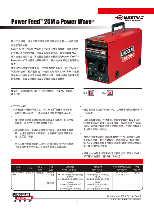
Power Feed ™ 25M & Power Wave ®• TOTAL s2f ™ 铝焊接解决方案– 从设备到焊材到焊接工艺,TOTAL s2f ™是林肯电气完善 的铝焊接解决方案——高质量及高价值的焊接解决方案。
• 标配的推拉丝送丝功能– 推拉丝功能能提供稳定的送丝功能及灵活使用不同长度焊 枪电缆,从而产生优良的铝焊接性能。
• 坚固耐用,适用于建筑施工– 结构坚固耐用,能适应恶劣的施工环境。
从建筑施工到造 船,该设计都能满足您的要求。
包装标配结实耐用的铝外 壳,选配塑料外壳。
• 内部照明– 您正工作在光线微弱的环境中吗?我们在系统中为您配备 了高亮度的发光二极管,以照亮内部送丝驱动部分。
林肯优势• 内部加热– 通过提供加热功能和外壳封闭,从而确保持续控制所用焊 材的湿度。
• 模式选择面板 (MSP4)– 采用高科技制造,方便使用。
Power Feed ™ 10M 中采用 的模式选择面板如今升级为便携式。
该面板为进入Power Wave ®波形模式调用提供了方便的路径。
先进的控制和设 置选项就在您的指尖处。
• 双程序和存储按钮– 双程序功能使您能够设置A 和B 两种程序以简化操作过程 中的程序转换。
有了存储按钮,您就无需记住程序内容! 操作人员只要简单按下按钮就可获得相应的波形和选定适 用于其应用的操作范围。
• 便携– 可通过一16英寸(406毫米)直径圆孔或12x18英寸(305 x 457毫米)椭圆孔,重35磅(15.9公斤)。
MIG 焊, 脉冲MIG 焊,STT ®,药芯焊丝焊,手工焊, TIG 焊,碳弧气刨焊接工艺系统便携式设计、高质量的焊接解决方案!针对工业领域,满足您的焊接需求的焊接解决方案——这不就是您苦苦寻找的吗?Power Feed ™/Power Wave ®系统沿袭了林肯的传统,能提供先进的控制、高性能的焊接、可靠及高质量的产品。
多功能汽车应急启动电源说明书
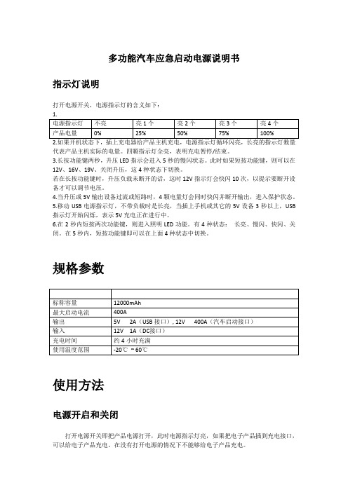
多功能汽车应急启动电源说明书指示灯说明打开电源开关,电源指示灯的含义如下:2.如果开机状态下,插上充电器给产品主机充电,电源指示灯循环闪亮,长亮的指示灯数量代表产品主机实际的电量。
四颗指示灯全亮,表明充电暂停/结束。
3.长按功能键两秒,升压LED指示会进入5秒的慢闪状态。
此时如果短按功能键,则可以在12V、16V、19V、关闭升压,这4种状态下切换。
若在长按功能键时,升压负载未断开的话,这时12V指示灯会快闪10次,以提示要断开设备才可以调节电压。
4.当升压或5V输出设备过流或短路时,4颗电量灯会同时快闪并断开输出,进入保护状态。
5.移动USB电源指示灯,不带负载时是长亮,当插上手机或其它的5V设备3秒以上,USB 指示灯开始闪烁,表示5V充电正在进行中。
6.在2秒内短按两次功能键,则进入照明LED功能。
有4种状态:长亮、慢闪、快闪、关闭。
在5秒内,短按功能键即可以在上面4种状态中切换。
规格参数5V2A(USB接口), 12V400A(汽车启动接口)12V1A(DC接口)使用方法电源开启和关闭打开电源开关即把产品电源打开,此时电源指示灯亮,如果把电子产品插到充电接口,可以给电子产品充电。
在没有打开电源的情况下不能够给电子产品充电。
给产品主机充电充电方法一:1.将配备的15V/1.5A旅行充电器插入充电插座(100-240V);2.将旅行充电器的DC插头插入主机12V的DC 输入口。
充电方法二:1.将车载充电器的一端插入车辆上的烟插;2.将车载充电器的DC插头插入主机12V 的DC输入口。
以上两种方法充电时,电源指示灯依次不停闪烁,表示充电正在进行,充满后电源指示灯全亮,不再闪烁,表示已经充满。
以上给产品充电的时间约为4小时,即可将产品完全充满电。
给12V汽车启动1.确认主机电源指示灯电量指示在2颗或2颗以上。
2.将红色电瓶夹夹紧电瓶正极(+),黑色电瓶夹夹紧电瓶的负极(-)。
3.将电瓶线插头插入主机12V 的EC5汽车启动专用输出口。
多功能电源使用说明书
多功能电源使用说明书一、前言多功能电源是一种便携式电源设备,具有多种功能,方便用户在不同场景下使用。
本使用说明书旨在为用户提供详细的操作说明,确保您能正确、安全地使用该设备。
二、产品概述多功能电源是一款集电源输入、输出、充电及其他辅助功能于一体的设备。
主要特点如下:1. 输入方式:支持AC电源输入和太阳能板输入。
2. 输出方式:提供USB接口和直流输出接口。
3. 充电功能:内置充电宝,可为移动设备充电。
三、使用环境多功能电源适用于室内和室外各类环境。
请确保使用环境干燥、通风,并避免阳光直射以及与易燃物品放置过近。
四、操作步骤以下为多功能电源的操作步骤,请仔细阅读并按照指示进行操作。
1. 电源输入a. AC电源输入:将AC适配器插入电源插座,并将适配器插头连接到多功能电源的AC输入接口。
b. 太阳能板输入:将太阳能板插头连接到多功能电源的太阳能输入接口,并确保太阳能板充分暴露在阳光下。
2. 电源输出a. USB接口输出:使用标准USB数据线将移动设备连接到多功能电源的USB接口,即可为移动设备充电。
b. 直流输出接口:根据需要选择合适的直流输出接口,将设备的输入插头与多功能电源的直流输出接口连接。
3. 充电功能a. 多功能电源支持通过AC电源和太阳能板对内置充电宝进行充电。
b. 将充电器插头插入电源插座,并连接到多功能电源的AC输入接口,即可对多功能电源进行充电。
c. 将太阳能板插头连接到多功能电源的太阳能输入接口,并确保太阳能板充分暴露在阳光下,即可对多功能电源进行充电。
4. 其他功能a. 多功能电源还具有XXX功能(根据具体产品功能进行描述),操作方式请参照附带的说明书。
b. 如需了解更多功能的操作方法,请参阅附带的完整说明书。
五、注意事项使用多功能电源时,请注意以下事项以确保安全:1. 请勿在高温、潮湿或易燃物附近使用多功能电源。
2. 请勿使用损坏的电源线或适配器。
3. 请勿将多功能电源的各部分进行拆卸或修理,以免造成危险。
用于CRH380型动车组检修的多功能外接电源[实用新型专利]
![用于CRH380型动车组检修的多功能外接电源[实用新型专利]](https://img.taocdn.com/s3/m/423453a8336c1eb91b375d34.png)
专利名称:用于CRH380型动车组检修的多功能外接电源专利类型:实用新型专利
发明人:乔雷,马丽格,石超,夏丽芳
申请号:CN202021659304.6
申请日:20200811
公开号:CN212691341U
公开日:
20210312
专利内容由知识产权出版社提供
摘要:本实用新型公开了用于CRH380型动车组检修的多功能外接电源,包括电源本体、外壳和固定座,所述电源本体的外侧设有外壳,外壳的一侧对应电源本体设有壳门,外壳的下端设有固定座,所述外壳的顶端对称安装有盖板,盖板转动连接外壳,盖板的下端对称固定连接有支撑块,使用时,电源本体位于外壳内部,对电源本体起到保护的作用,利用防滑垫能起到防滑的作用,利用套管、活动杆、夹板和弹簧对电源本体的两端进行限位,将外壳放入固定座中,滑块沿着滑槽滑动,利用插销将固定套一和支撑柱固定,螺栓将固定套二与支撑腿固定,底座与地面接触,对外壳起到支撑的作用,盖板呈闭合状态,可供工作人员休息使用。
申请人:乔雷
地址:130062 吉林省长春市绿园区长客路2001号预组三期306
国籍:CN
更多信息请下载全文后查看。
