台湾川得CHUNDE压力传送器CPG
DYSS-G8 液压缓冲器操作说明书
1适用文件•请遵守小型滑台式气缸 DGST 的操作说明书。
2安全2.1安全注意事项–仅在原装状态下使用产品,请勿擅自进行改动。
–请注意产品上的各种标识。
–在产品上作业前:关断电源,并做好防重启保护。
2.2按规定使用该产品设计用于小型滑台式气缸 DGST 的缓冲和滑块终端位置调整。
该产品不适合在潮湿的环境中使用。
2.3专业人员的资质关于产品的一切工作仅允许由具备资质的专业人员进行,这些专业人员对工作进行评估并识别出危险。
专业人员经过机械方面的培训。
3其他信息–技术问题请联系当地 Festo 联络人 è .–附件和备件 è /catalogue。
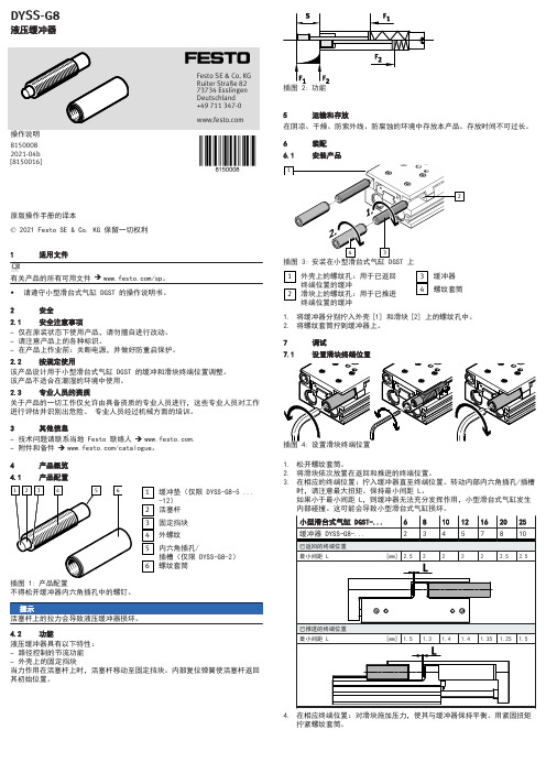
4产品概览4.1产品配置插图 1:产品配置缓冲垫(仅限 DYSS-G8-5 ...-12)活塞杆固定挡块外螺纹内六角插孔/插槽(仅限 DYSS-G8-2)螺纹套筒不得松开缓冲器内六角插孔中的螺钉。
4.2功能液压缓冲器具有以下特性:–路径控制的节流功能–外壳上的固定挡块当力作用在活塞杆上时,活塞杆移动至固定挡块。
内部复位弹簧使活塞杆返回其初始位置。
5运输和存放在阴凉、干燥、防紫外线、防腐蚀的环境中存放本产品。
存放时间不可过长。
6装配6.1安装产品插图 3:外壳上的螺纹孔:用于已返回终端位置的缓冲滑块上的螺纹孔:用于已推进终端位置的缓冲缓冲器螺纹套筒1.将缓冲器分别拧入外壳 [1] 和滑块 [2] 上的螺纹孔中。
2.将螺纹套筒拧到缓冲器上。
7调试1.松开螺纹套筒。
2.将滑块依次放置在返回和推进的终端位置。
3.在相应的终端位置:拧入缓冲器直至终端位置。
转动内部内六角插孔/插槽时,请注意最大扭矩。
保持最小间距 L。
如果小于最小间距 L,则缓冲器无法充分发挥作用,小型滑台式气缸发生内部碰撞。
这可能会导致小型滑台式气缸损坏。
4.在相应终端位置:对滑块施加压力,使其与缓冲器保持平衡。
用紧固扭矩拧紧螺纹套筒。
7.2执行试运行•请遵守小型滑台式气缸 DGST 的操作说明书。
SONG CHUAN 178 205 双极性双向电源电磁闸说明书
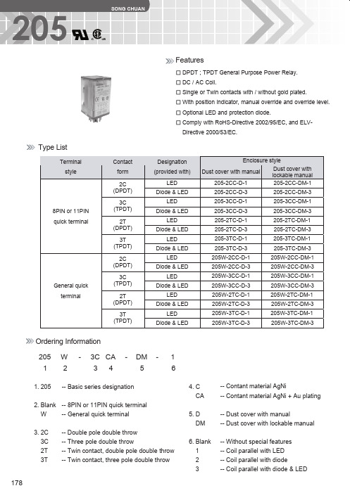
◆ CSA / CUS 2C
10A 240VAC 6A 24VDC
0.3A 240VDC 0.6A 120VDC 1/2HP 120VAC / 240VAC
3C 6.6A 240VAC 10A 120VAC
6A 24VDC 0.3A 240VDC 0.6A 120VDC
3C 6.6A 240VAC 10A 120VAC
(V) 24 48 60 110 115 230
Coil resistance ±10 % at 23˚C
(Ω) 74 303 474 1,710 1,710 7,500
Max. continuous voltage at 40˚C
110% of rated voltage
Pick up voltage(Max)
Drop out Power consumption
voltage ±10 % at 23˚C ±10 % at 23˚C
voltage
voltage(Max) voltage(Min)
at rated
(V)
(mA)
12
125
( Ω)
at 60˚C
at 23˚C
at 23˚C
voltage
96
24
63
Directive 2000/53/EC.
Contact form
2C (DPDT)
3C (TPDT)
2T (DPDT)
3T (TPDT)
2C (DPDT)
3C (TPDT)
2T (DPDT)
3T (TPDT)
Designation (provided with)
LED Diode & LED
SD-877C Neo Dry系列干式真空泵使用说明书
SD-877CNeo Dry系列干式真空泵型 号NeoDry15C使 用 说 明 书日 期 记 录12.05制作使用说明书此说明书描述了NeoDry系列干泵的安装、操作以及保养方法。
安装及操作干泵前,请一定详细阅读此使用说明书,并按照书中所示正确进行操作。
为确保使用安全,请特别注意以下警告语。
危 险注 意此标志指示存在危险,如果不按照说明书进行操作,可能会导致操作人员轻度或中等受伤。
确 认此标志表示,如果不按照说明书进行操作,可能会造成机器损坏。
<说明书的存放>本说明书描述了使用干泵时的注意事项。
请将此说明书置于视线范围内,以便随时查阅。
<用语定义>书中出现的部分用语的定义如下。
溶 剂: IPA、乙醇冷凝气体: 水蒸气或者混入溶剂的气体※例抽除溶剂时,请根据溶剂的种类和无论抽气量,请务必事前向本公司各营业部咨询。
包括上述溶剂在内,抽除可燃性气体时,请务必先从气镇装置口导入氮气。
干泵的保证购买此泵后的两年内,任何由于本公司的责任(如设计、材料、制造上的缺陷)而导致设备故障的,本公司将免费提供维修服务或者更换新设备。
但是,未按照使用说明书指示而自行进行操作所造成的故障,本公司将不予负责。
另外,下记保障以外的项目中的内容不在保修内。
请根据以下的工艺设定保修周期。
不同工艺的保修周期年保修抽除水蒸气、混入溶剂的气体1・・・(关于抽除溶剂时,请根据种类和抽气量,向本公司各营业部咨询。
)2・・・年保修抽除大气、氮气、洁净工艺以下项目不在保修范围内・因操作、存放不当导致的故障。
・抽除酸碱性、腐蚀性等特殊气体造成的损害,或者抽吸含有大量固体物质或可凝结的物 质混入较多时导致的故障。
・因未进行必要的保养而引起导致的故障。
・由于使用了本公司以外的零部件而导致的故障。
・非本公司或未经本公司认可的工厂,或操作人员进行维修,辅修改造所造成的故障。
・火灾、洪水、地震、雷电或其他不可抗力起因所导致的故障。
另外,本公司承诺的保修范围,仅限于有缺陷的维修和更换设备的受损部分,对于因此 而产生其他损失原则上不在保证范围内。
详细配置清单及报价明细表
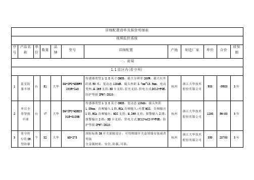
浙江大华技术股份有限公司
3400
27200
3年
4
枪机支架
个
36
大华
DH-PFB120WS
铝合金支架,订制;
杭州
浙江大华技术股份有限公司
35
1260
3年
5
球机支架
个
8
大华
DH-PFB303WC
铝合金支架;
杭州
浙江大华技术股份有限公司
50
400
3年
6
全自动光盘刻印机
台
1
派美雅
Bravo 4202
光盘容量: 全自动100片光盘输入/输出,左边50片输出桶,右边50片输入桶 , 100片外部输出桶;
光盘打印刻录速度: DVD-R≥24片/小时;CD-R≥42片/小时;打印方式:喷墨;
刻录机刻录速度: DVD±R: 24X ; DVD±R DL: 12X ; CD-R: 48X
兼容Windows 7/8/10,Server2012/2016和Mac OS X 10.6或更高操作系统
北京
北京英特信网络科技有限公司
杭州
浙江大华技术股份有限公司
1200
1200
3年
4
拾音器
个
30
大华
HS-29S
全向拾音,5-150平方米拾音范围,
金属材质
高保真微机电系统(MEMS)硅麦克风,
信噪比82dB,
Ambient &noise cancellation(ANC)环境噪声消除技术,自适应算法降低噪音
对有效声音信号采用宽动态范围处理技术,同时兼顾较大和较小声音信号的处理
工作环境温度 :-25℃~70℃
DPS双路控制器使用说明书

3、编程状态
1)、按钮
z 白色“↑”按钮:系统自动状态时,用来修改设定值;手动状态时,用来控制电动阀的开;在编程状态时, 用来选择功能号、移位(由高位到低位);
z 白色“↓”按钮:系统自动状态时,不起作用;手动状态时,用来控制电动阀的关;编程状态时,用来选 择功能号、输入数字;
z 绿色“运行”按钮:带指示灯,灯亮时表示系统处于自动状态,按下灯灭进入手动状态。点按按钮,指示 灯在“灭”和“亮”之间转换。
z 红色“功能”按钮:在自动状态时,按下红色数码管显示功能号“F00”,可按“↑”或“↓”按钮选择功 能号;在手动状态时,用来转换数码管的显示(见图 2)
2)、数码管显示窗
z 红色数码管:在自动或手动状态下,“KPa”前的指示灯亮时,显示的数字单位:KPa;“cm”前的指示灯 亮时,显示的数字单位:cm (厘米);在编程状态下,显示功能号;
DPS 双路控制器可以连接 2 台变送器(4-20mA 输出)和 2 台电动调节阀,电动调节阀的阀位信号可以是触 点型、电位器模拟型或无阀位信号。还有 1 路报警控制(触点型),还可以通过 RS485 总线与计算机联网。在 纸机出现断纸时,只需按下断纸处理按钮即可快捷地完成相应控制回路的处理工作;暖缸功能可完成烘缸预热 处理工作。
2
二、控制器工作状态
绵阳海天测控技术有限责任公司 2000 年 9 月 8 日
1、自动状态
绿色“运行”按钮指示灯亮,系统自动控制。
开机时,显示:
检测值 设定值
1.68
KPa cm
0.60
设定 阀位
按“运行”按钮,指示 灯灭,按 1 次 红色“功 能”按钮,再按“运行” 按钮,指示器亮。显示
莫克维迪轴流式调节阀
MOKVELD轴流式控制阀的特点及常见问题处理1 川气东送站场压力控制系统简介川气东送站场压力控制系统是由安全切断阀(SSV)、监控调压阀(PCV)、工作调压阀(PV)按照从上游至下游的顺序,串联在一起的安全、监控式调压系统(调压橇)。
安全切断阀OSE、监控调压阀FL、工作调压阀MOKVELD为相互独立的设备。
正常情况下,安全切断阀和监控调压阀处于全开位置,由工作调压阀对下游压力进行控制。
当工作调压阀出现故障,无法控制下游压力时,监控调压阀开始工作,以维持下游压力的安全范围。
若监控调压阀也出现故障,不能控制下游压力,安全切断阀则自动切断气源,同时控制机柜开启备用回路,以保证下游管道和设备的安全。
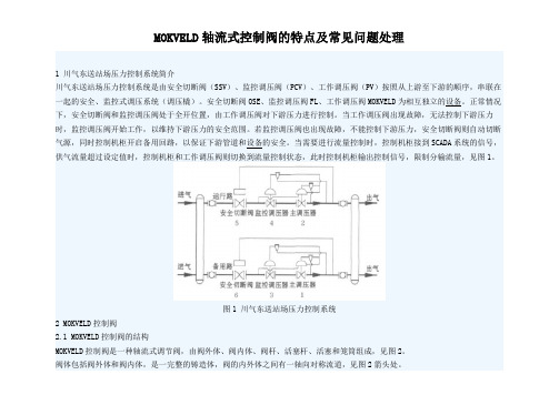
当需要进行流量控制时,控制机柜接到SCADA系统的信号,供气流量超过设定值时,控制机柜和工作调压阀则切换到流量控制状态,此时控制机柜输出控制信号,限制分输流量,见图1。
图1 川气东送站场压力控制系统2 MOKVELD控制阀2.1 MOKVELD控制阀的结构MOKVELD控制阀是一种轴流式调节阀,由阀外体、阀内体、阀杆、活塞杆、活塞和笼筒组成,见图2。
阀体包括阀外体和阀内体,是一完整的铸造体,阀的内外体之间有一轴向对称流道,见图2箭头处。
笼筒是减压阀的关键部件,壁面上有许多孔洞,MOKVELD控制阀选用三层笼筒,即笼筒壁面分三层,每层按一定规律分布有许多孔洞,三层壁面按一定的要求组合为一体。
活塞杆与阀杆构成一个90°的角式传动机构(见图2),活塞借助此传动机构在导轨内沿阀门的中心线运动,活塞杆与阀杆上4 5°的齿条相互啮合,阀杆上下传动,带动活塞杆及活塞在全行程上左右运动。
活塞的端面上均匀分布有孔洞,以使活塞内外压力平衡,左右运动时不受轴向压力的影响。
1)阀外体;2)阀内体;3)活塞杆;4)阀杆;5)活塞;6)笼筒图2 MOKVELD控制阀结构示意图2.2 MOKVELD控制阀的特点2.2.1 介质的轴流性由于采用轴向对称流道,完全避免了间接流和流向不必要的改变,最大限度地提高了单位直径上的流通能力,大大降低了噪音和紊流的形成,并可以防止上游未经过处理的流体腐蚀阀门。
Schneider-Electric IHP 1C 2C 定时器控制器用户指南说明书
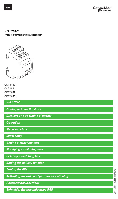
d d _E N 02/19IHP 1C/2CProduct information / menu descriptionCCT15440CCT15441CCT15442CCT15443d d _E N 02/19The IHP with weekly program controls lighting, air conditioning, flushing, etc.|The device must not control safety-relevant applications.G etting to know the timerDisplays and operating elementsA Time displayB Channel stateC Date displayD Programmed ON timesE Display of week daysF Display of active buttonsG OK buttonH Selection buttonsI MENU buttonOperationButton FunctionMENU button•Opens the menu•In menu mode: one step back:•In programming mode: cancel programming modeSelection buttons •Switch between menu items •Increase/decrease value OK button•In menu mode: select menu item •In programming mode: confirm settingMenu structurePROGRAM TIME/DATEMANUAL CONFIG ENDCHANNEL 1TIME CHANNEL 1LANGUAGENEW SET DATEPERM ON PIN CHECK SU-WI PERM OFF FACTORY SETTINGSMODIFY WEEK DAY OVERRI ONINFO DELETEFORM DATE HOLIDAYENDENDFORM TIMEENDd d _E N 02/19The basic settings, such as date, time, etc., must be carried out when starting for the first time or following a reset.The device starts in the settings menu with the item LANGUAGE .1Select the language.2Confirm the message FORM DATE .3Select the date format.4Set the year.5Set the month.6Set the day.7Confirm the message FORM TIME .8Select the time format.9Set the hours.0Set the minute.^Select summer time/winter time.A switching time always consists of one time at which the load is switched on and one time at which the load is switched off. Y ou can either set switching times for a specific day of the week or copy them for multiple week days. Copied week days are referred to as a block.T o set a switching time, perform the following steps once for ON and once for OFF :1Confirm message about free memory slots.2Select ON or OFF .3Set the hour.4Set the minute.5Set the day of the week.6If the switching time is only to be valid for one week day, select SAVE .The switching time is set.7If the switching time is to be copied as a block for multiple week days, select COPY .8Select further days of the week and confirm in each case.Week days contained in the block are indicated in the week days display.To remove a week day from the block, select the week day again using the selection buttons.9Once the desired week days have been set, select COPY .Initial setupSetting a switching timePROGRAMCHANNELC1CHANNELC2NEWNEWd d _E N 02/19Y ou can change the time for the switching times. In the case of switching times within a block, you can select whether the modification of the time is to apply to the whole block or only to a specific week day. This week day is then removed from the block.1Select the switching time.The display runs through all switching times in sequence. If no switching time is set for a week day, this is indicated in the display by --:--.If the selected switching time is part of a block, all days of the block are shown in the week day display. The selected week day flashes.2Set the hour.3Set the minute.4If the selected switching time is only set for one week day, only the option SAVE appears.5If the selected switching time is part of a block, select MODIFY BLOCK or MODIFY WEEK DAY .- MODIFY BLOCK changes the time for all switching times of the block.- MODIFY WEEK DAY changes the time for the selected switching time. The selected switching time is re-moved from the block.Y ou can delete switching times at any time. If a switching time is part of a block, you can delete the entire block or remove the switching time from the block. Y ou can also delete all switching times of a channel simultaneously.Deleting a switching time:1Select SINGLE .2Select the switching time.The display runs through all switching times in sequence. If no switching time is set for a week day, this is indicated in the display by --:--.If the selected switching time is part of a block, all days of the block are shown in the week day display. The selected week day flashes.3If the selected switching time is only valid for one week day, only the option DELETE WEEK DAY appears.4If the selected switching time is part of a block, select DELETE BLOCK or DELETE WEEK DAY .- DELETE BLOCK deletes all switching times of the block.- DELETE WEEK DAY removes the selected switching time from the block and deletes it.Deleting all switching times of a channel:1Select DELETE ALL .2Confirm with CONFIRM .Modifying a switching timePROGRAMCHANNELC1CHANNELC2MODIFYMODIFYDeleting a switching timePROGRAMCHANNELC1CHANNELC2DELETEDELETEd d _E N 02/19With the holiday function, you can switch a channel on or off completely for a longer period. The programmed switching times do not apply while the holiday function is active. Y ou can only set one holiday time per channel.1Select ON or OFF .2Confirm BEGIN HOLIDAY .3Set the year.4Set the month.5Set the day.6Set the hour.7Confirm END HOLIDAY .8Set the year.9Set the month.0Set the day.^Set the hour.A PIN protects against unauthorized use.If you have forgotten your PIN, contact the Customer Care centre in your country, stating the serial number of your device.1Select WITH PIN .NO PIN cancels the PIN protection function.2Confirm CURRENT PIN .3Set new PIN.|The PIN digits are set one after the other with +/- and confirmed with OK . A digit that has already been set can no longer be changed. When the last digit is confirmed with OK , the PIN is saved. If in any doubt, exit the PIN setting procedure with MENU .Setting the holiday functionMANUALCHANNELC1CHANNELC2HOLIDAYHOLIDAYSetting the PINCONFIGPINd d _E N 02/19Y ou can set override or permanent switching either via the MANUAL menu or using combinations of buttons on the device.Override switchingIf you wish to switch a channel briefly to the other switching state (e.g. from ON to OFF ), activate override. This state is only valid until the next switching time.If override is active, CHANNEL OVERRIDE appears briefly in the display.Permanent switchingIf you wish to switch a channel permanently, activate permanent switching. While permanent switching is activat-ed, switching times have no effect.If you want to select whether the channel is to be switched ON or OFF permanently, use the MANUAL menu.If you use the button combinations to activate permanent switching, the channel is switched to the other switching state (e.g. from ON to OFF ).If permanent switching is active, CHANNEL PERMANENT appears briefly in the display.Activating override and permanent switchingd d _E N 02/19Y ou can reset the basic settings, such as date, time, etc. and delete or keep all switching times.Y ou have two options: Y ou can either load the factory settings via the CONFIG menu or reset the device using combinations of buttons on the device.|Loading the factory settings will also delete all switching times. If you want to reset the basic settings and retain the switching times, use the reset function.Loading factory settings1Confirm the message LOAD FACTORY SETTINGS .2Set basic settings as described in chapter “Initial setup”.Resetting1Push all four buttons on the device simultaneously.2Select the language.3If you want to retain the switching times, select RETAIN PROGRAMS .4If you want to delete all switching times, select DELETE PROGRAMS .5Set basic settings as described in chapter “Initial setup”.If you have technical questions, please contact the Customer Care Centre in your /contactResetting basic settingsCONFIGFACTORY SET-TINGSSchneider Electric Industries SAS。
Endevco 压电式加速度计(PE) 选择指南
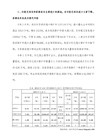
49Endevco 压电式加速度计(PE) 选择指南型号灵敏度 (pC/g) 重量 (克) 线性范围 (g)冲击极限(g)频率响应(Hz) 最低温度(℃) 最高温度 (℃) 信号/地 绝缘 气密封安装方法压电式(PIEZOELECTRIC) 12M1 22 23 2220D 2221D 2221F 2222C 2223D 2224C 2225 2225M5A 2226C 2228C 2229C 2 0.4 0.4 3 17 10 1.4 12 12 0.75 0.025 2.8 2.8 2.8 0.085 0.14 0.8 3.1 12 11 0.5 41 16 13 13 2.8 15 4.9 504000200010001000100010001000100010000100001000100010001000100001000050005000300010000200020002000100002000200020001~28001~100001~100001~100001~60001~100001~80001~60001~60001~80001~80001~50001~40001~5000-65 -73 -73 -55 -55 -55 -73 -55 -55 -55 -55 -55 -55 -55 149 149 149 260 177 260 177 177 177 177 177 177 177 177 N/A 是 是 是 是 非 是 是 非 非 非 非 是 是 N/A 非 非 是 非 是 非 非 非 非 非 非 非 非 粘接 粘接 粘接 螺纹 螺纹 螺纹 螺纹 螺纹 螺纹 螺纹 螺纹 粘接 螺纹 螺纹 2248 2271A 2271AM20 2272 2273A2273AM1/AM20 22762.5 11.5 11.5 13 3 10 10 13 27 27 27 25 32 30 5001000100010001000500500300010000100002000100003000300010~10001~40001~40001~50001~60001~50001~5000-55 -269 -269 -269 -184 -55 -55 482 260 260 260 399 399 482 非 是 是 非 非 是 非 是 是 是 是 是 是 是 螺纹 螺纹 螺纹 螺纹 螺纹 螺纹 螺纹 6222S-20A 6222S-50A 6222S-100A 6233C-10 6233C-50 6233C-100 6237M70 6237M71 6240C-10 6240M10 20 50 100 10 50 100 10 10 10 5 91 91 91 75 110 110 30 30 200 95 2000100050010001000500500500100025040002000100020002000100020002000200010001~90001~60001~600010~500010~250010~20002~50002~50005~25002~2000-55 -55 -55 -55 -55 -55 -55 -55 -55 -55 260 260 260 482 482 482 649 649 649 760 是 是 是 是 是 是 是 是 是 是 是 是 是 是 是 是 非 非 是 是 螺纹 螺纹 螺纹 螺纹 螺纹 螺纹 螺纹 螺纹 螺纹 螺纹 7201-10 7201-50 7201-100 7221A 7240B 7701A-50 7701A-100 7701A-200 7701A-1000 7702A-17 7702A-50 7703A-50 7703A-100 7703A-200 7703A-1000 7704A-17 7704A-50 7722/772410 50 100 10 2.7 50 100 200 1000 17 50 50 100 200 1000 17 50 3.718 24 25 11 4.8 25 29 62 120 25 25 25 29 62 120 25 25 292000200020001000100020001000850500250020002000100085050025002000500200001000050005000500010000500020001000120001000010000500020001000120001000025001~120001~60001~50001~100001~150001~60001~50001~40001~20001~100001~60001~60001~50001~40001~20001~100001~60001~4000-73 -73 -73 -55 -55 -55 -55 -55 -55 -55 -55 -55 -55 -55 -55 -55 -55 -269260 260 260 177 260 288 288 288 288 288 288 288 288 288 288 288 288 177非 非 非 非 非 非 非 非 非 非 非 是 是 是 是 是 是 非/是是 是 是 是 是 是 是 是 是 是 是 是 是 是 是 是 是 是 螺纹 螺纹 螺纹 螺纹 螺纹 螺纹 螺纹 螺纹 螺纹 螺纹 螺纹 螺纹 螺纹 螺纹 螺纹 螺纹 螺纹 螺纹50度计不仅具有长时间的稳定性,且可在-269℃~+750℃的范围内使用,性能稳定可靠。
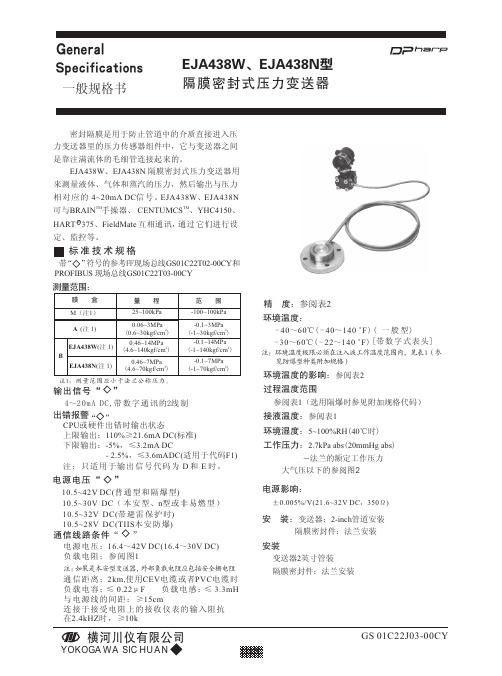
横河川仪 EJA438W EJA438N型隔膜密封式压力变送器 说明书
膜盒 时间常数(秒)
M 约 0.3
A 约 0.2
B 约 0.2
放大器外壳 铝合金铸件或JIS SCS14A 不锈钢
喷漆 深海苔绿色(Munsell 0.6GY3.1/2.0)
表头 LCD数字表头(可选)
变送器材质 容室法兰:JIS SCS14A 螺栓、螺母:见型号规格表 隔膜密封件材质:
隔膜及其它接液部件:参阅“型号与规格代码一览表” 毛细管:JIS SUS316 保护管:JIS SUS304 PVC 屏蔽(PVC的最大使用温度:100℃)(212oF) 注入液:参阅表 1 出厂时设定值:
当毛细管长 5m,注入液的代码为A,过程法兰为3 英寸时,在正常温度下取得的值。 外部调零 在 测 量 范 围 内 零 点 连 续 可 调 , 分 辩 率 为0.01%。
调零 在膜盒量程的上下限范围内,零点可任意调整
位号牌:JIS SUS304
重量 8.3kg(18.31bs)(EJA438W,带2-inch JIS 10K
±(0.2+0.5× Pref )% /50℃ X
X< Pref ±(0.3+0.6× Pref )% /50℃ X
±1.4%/50℃
X≥Pref ±1.6%/50℃
X≥Pref
±(0.7+0.7× Pref)%/50℃ X
X< Pref
±(0.8+0.8× Pref )%/50℃变化 X
X< Pref
~法兰的额定工作压力 大气压以下的参阅图2
电源影响:
±0.005%/V(21.6~32V DC,350Ω)
安 装:变送器:2-inch管道安装 隔膜密封件:法兰安装
安装 变送器2英寸管装 隔膜密封件:法兰安装
Richtek RT9194 低滴通线性调压器控制器说明书
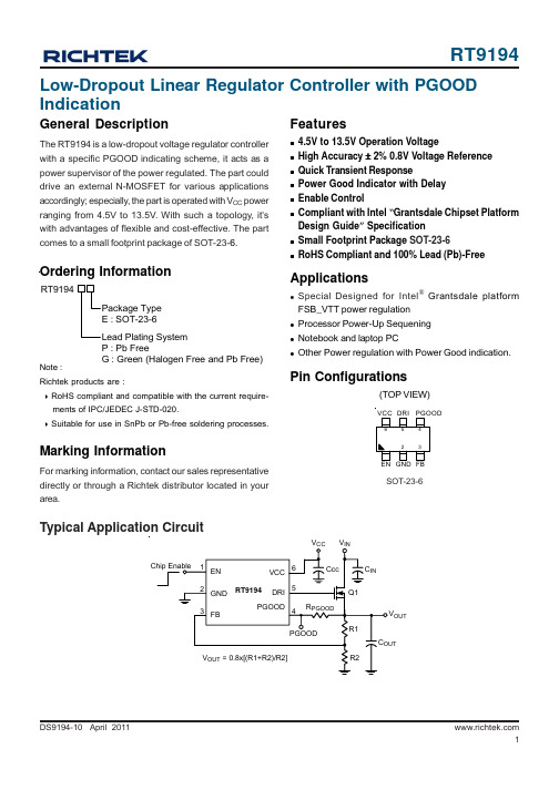
Test CircuitFigure 1. Typical Test CircuitFigure 2. DRI Source/Sink Current Test CircuitV CC VOUTV CC DRIAbsolute Maximum Ratings (Note 1)z Supply Input Voltage, V CC-----------------------------------------------------------------------------------------15Vz Enable Voltage-------------------------------------------------------------------------------------------------------7Vz Power Good Output Voltage---------------------------------------------------------------------------------------7Vz Power Dissipation, P D @ T A = 25°CSOT-23-6---------------------------------------------------------------------------------------------------------------0.4Wz Package Thermal ResistanceSOT-23-6, θJA---------------------------------------------------------------------------------------------------------250°C/Wz Lead Temperature (Soldering, 10 sec.)-------------------------------------------------------------------------260°Cz Junction T emperature-----------------------------------------------------------------------------------------------150°Cz Storage T emperature Range---------------------------------------------------------------------------------------−65°C to 150°C z ESD Susceptibility (Note 2)HBM (Human Body Mode)-----------------------------------------------------------------------------------------2kVMM (Machine Mode)------------------------------------------------------------------------------------------------200V Recommended Operating Conditions (Note 3)z Supply Input Voltage, V CC-----------------------------------------------------------------------------------------4.5V to 13.5Vz Enable Voltage-------------------------------------------------------------------------------------------------------0V to 5.5Vz Junction T emperature Range--------------------------------------------------------------------------------------−40°C to 125°C z Ambient T emperature Range--------------------------------------------------------------------------------------−40°C to 85°C Electrical CharacteristicsTo be ContinuedTypical Operating CharacteristicsQuiescent Current vs. Temperature0.450.460.470.480.490.5-50-25255075100125Temperature Q u ie s c e n t C u r r e n t (m A )(°C)Feedback Voltage vs. Temperature0.70.750.80.850.9-50-25255075100125Temperature F e e d b a c k V o l t a g e (V )(°C)R e f e r t o T e s t C i r c u i t F i g u r e 1PGOOD Delay Time vs. Temperature1.522.533.54-50-25255075100125Temperature P G O O D D e l a y T i m e (m s )(°C)DRI Sink Current vs. Temperature12151821242730-50-25255075100125Temperature D R I S i n k C u r r e n t (m A )(°C)Sink Current vs. DRI Voltage05101520250.511.522.53DRI Voltage (V)S i n k C u r r e n t (m A )DRI Source Current vs. Temperature354045505560-50-25255075100125Temperature D R I S o u r c e C u r r e n t (m A )(°C)R e f e r t o T e s t C i r c u i t F i g u r e 1Load Transient Response020-205V IN = 2.5V, V OUT = 1.2V C IN = C OUT = 100uF Time (50us/Div)V CC = 12VC IN = C OUT = 100uFR e f e r t o T e s t C i r c u i t F i g u r e 1I Load (A)V EN (V)V OUTV PGOODV CC = 12V, C IN = C OUT = 100uF , I LOAD = 100mAR e f e r t o T e s t C i r c u i t F i g u r e 1V EN (V)V OUT V PGOODR e f e r t o T e s t C i r c u i t F i g u r e 1Capacitors SelectionCareful selection of the external capacitors for RT9194 is highly recommended in order to remain high stability and performance.Regarding the supply voltage capacitor, connecting a capacitor which is 1μF between V CC and ground is a must. The capacitor improves the supply voltage stability to provide chip normally operating.Regarding the input capacitor, connecting a capacitor which 100μF between V IN and ground is recommended to increase stability. With large value of capacitance could result in better performance for both PSRR and line transient response.When driving external pass element, connecting a capacitor 100μF between V OUT and ground is recommended for stability. With larger capacitance can reduce noise and improve load transient response and PSRR.Output Voltage SettingThe RT9194 develop a 0.8V reference voltage; especially suit for low voltage application. As shown in application circuit, the output voltage could easy set the output voltage by R1 & R2 divider resistor.Power Good FunctionThe RT9194 has the power good function with delay. The power good output is an open drain output. Connect a 100kΩ pull up resistor to V OUT to obtain an output voltage. When the output voltage arrive 90% of normal value the power good will output voltage with 3ms delay time.When the output voltage falling arrive 75% of normal value the power good will turn off with less than 1ms delay time. But, there are two exceptions. One is the enable pull low the power good will turn off quickly. The second is the V CC falling arrive POR value (4V typ.) the power good also will turn off quickly.Chip Enable OperationPull the EN pin low to drive the device into shutdown mode. During shutdown mode, the standby current drops to 5μA(MAX). The external capacitor and load current determine the output voltage decay rate. Drive the EN pin high to turn on the device again.Under Voltage ProtectionRT9194 equips the V OUT under-voltage (UV) protection function. The UV protection circuits will start monitoring the power status after the PGOOD pin goes high. If the output voltage drops to below 75% of its setting value, the PGOOD and DRI pins will be pulled low and latch RT9194. The UV latch status will be released only when V CC or Enable pin goes low and returns high again, which will also cause RT9194 to re-activate.MOSFET SelectionThe RT9194 are designed to driver external N-Channel MOSFET pass element. MOSFET selection criteria include threshold voltage V GS (V TH), maximum continuous drain current ID, on-resistance R DS(ON) ,maximum drain-to-source voltage V DS and package thermal resistance θ(JA).The most critical specification is the MOSFET R DS(ON). Calculate the required R DS(ON) from the following formula:For example, the MOSFET operate up to 2A when the input voltage is 1.5V and set the output voltage is 1.2V, R ON = (1.5V-1.2V) / 2A = 150mΩ, the MOSFET's R ON have to select lower than 150mΩ. A Philip PHD3055E MOSFET with an R DS(ON) of 120mΩ(typ.) is a close match.And carry on consider the thermal resistance from junction to ambient θ(JA) of the MOSFET's package. The power dissipation calculate by :P D = (V IN − V OUT) x I LOADThe thermal resistance from junction to ambient θ(JA) calculate by :In this example, P D = (1.5V − 1.2V) x 2A = 0.6W. The PHD3055E's θ(JA) is 75°C/W for its D-PAK package, which translates to a 45°C temperature rise above ambient. The package provides exposed backsides that directly transfer heat to the PCB board.DAJ(JA)P)T(T−=θLOADOUTINDS(ON)IVVRNMOSFET−=Application InformationInformation that is provided by Richtek Technology Corporation is believed to be accurate and reliable. Richtek reserves the right to make any change in circuit design, specification or other related things if necessary without notice at any time. No third party intellectual property infringement of the applications should be guaranteed by users when integrating Richtek products into any application. No legal responsibility for any said applications is assumed by Richtek.Richtek Technology CorporationHeadquarter5F, No. 20, Taiyuen Street, Chupei City Hsinchu, Taiwan, R.O.C.Tel: (8863)5526789 Fax: (8863)5526611Richtek Technology CorporationTaipei Office (Marketing)5F, No. 95, Minchiuan Road, Hsintien City Taipei County, Taiwan, R.O.C.Tel: (8862)86672399 Fax: (8862)86672377Email:*********************Outline DimensionA1HSOT-23-6 Surface Mount Package。
GPG13 'M' 系列包装气机说明书

REPAIR PARTS®nufacturing Company, L.P. ◊5151 San Felipe, Suite 500 ◊RP-578AThis manual is to be used by qualified technicians only.This manual replaces RP-578.November 2014GPG13 "M" Series Package Gas Unit© 2009,2014 Goodman Company, L.P. ◊ 5151 San Felipe St., Suite 500 ◊ Houston, TX 77056GPG1324045M41AA GPG1324070M41AA GPG1330045M41AA GPG1330070M41AA GPG1336045M41AA GPG1336070M41AA GPG1336090M41AA GPG1336090M43AA GPG1342070M41AA GPG1342090M41AA GPG1348070M41AA GPG1348090M41AA GPG1348090M43AA GPG1348115M41AA GPG1360090M41AA GPG1360090M43AA GPG1360115M41AA GPG1360140M41AA GPG1360140M43AAImportant Information For assistance within the U.S.A. contact:For assistance outside the U.S.A. contact:IndexFunctional Parts List Per request from Service Parts Engineer: removed 0231K00039 from GPG1348115M41AA.Illustration and Parts......................................................................................................................................................................................................Views shown are for parts illustrations only, not servicing proceduresAR - As Required NA - Not Available NS - Not Shown00000000 - See NoteQTY - Quantity Example (QTY 3) (If Quantity not shown, Quantity = 1)M - Model Example (M1) (If M Code not shown, then part is used on all Models)Text Codes:ExampleM1 - Model#1 M2 - Model#2 M3 - Model#3Expanded Model Nomenclature:Goodman Company, L.P. is not responsible for personal injury or property damage resulting from improper service. Review all service information before beginning repairs.Warranty service must be performed by an authorized technician, using authorized factory parts. If service is required after the warranty expires, Goodman Company, L.P. also recommends contacting an authorized technician and using authorized factory parts.Goodman Company, L.P. reserves the right to discontinue, or change at any time, specifications or designs without notice or without incurring obligations. 2Consumer Affairs Department Goodman Company, L.P.7401 Security Way Houston, Texas 77040877-254-4729-Telephone 713-863-2382-FacsimileInternational DivisionGoodman Company, L.P.7401 Security Way Houston, Texas 77040713-861-2500-Telephone 713-863-2382-Facsimile 4 - 153RP-578AFunctional Parts PartNo:Description:B137075124V RELAY (M11, M12, M13, M14, M15, M16,M17, M18, M19)0131M00522BLOWER MOTOR - 1 HP PROGRAMMEDSELEC (M15, M16, M17, M18, M19)0131M00527BLOWER MOTOR - 1 HP PROGRAMMEDSELEC (M11, M12, M13, M14)11091202BLOWER MOTOR 1/3 HP, 3 SP, 6 PL (M3, M4) 11091203BLOWER MOTOR 1/3 HP, 3 SP, 6 PL (M5,M6, M7, M8, M9, M10)11091207BLOWER MOTOR 1/4 HP, 3 SP, 8 PL (M1, M2) CAP100000370LA CAPACITOR 10/370V (M1, M2, M3, M4, M5,M6, M7, M8, M9, M10)CAP050350440CS CAPACITOR 5/35/440V (M1, M2, M3, M4)CAP050000370LA CAPACITOR 5/370V (M8, M13, M16, M19) CAP050450440CT CAPACITOR 5/45/440V/DUAL RD (M5, M6,M7, M9, M10, M11, M12, M14)CAP050700440CT CAPACITOR 5/70/440V/DUAL RD (M15, M17,M18)ZP31K5EPFV130COMPRESSOR 31100, 208/230/60/1 (M5, M6,M7)ZP31K5ETF5130COMPRESSOR 31200, 200/230/60/3 (M8)ZP34K5EPFV130COMPRESSOR 34500, 208/230/60/1 (M9, M10) ZP39K5ETF5130COMPRESSOR 39000, 200/230/60/3 (M13)ZP39K5EPFV130COMPRESSOR 39000, 208/230/60/1 (M11,M12, M14)ZP51K5EPFV130COMPRESSOR 51000, 208/230/60/1 (M15,M17, M18)ZP51K5ETF5130COMPRESSOR 51000, 208/230/60/3 (M16,M19)760001-2001-20COMPRESSOR, BRISTOL (M1, M2)760005-2001-20COMPRESSOR, BRISTOL (M3, M4)0131M00061COND MOTOR 1/4 HP, 1 SP, 8 PL (M1, M2,M5, M6, M7, M8)0131M00429COND MOTOR 1/4 HP, 1 SP,6 PL (M3, M4,M9, M10, M11, M12, M13, M14, M15, M16,M17, M18, M19)CONT1P025024V CONTACTOR 25 AMP, 1P, 24V (M1, M2, M3,M4, M5, M6, M7)CONT3P025024V CONTACTOR 25 AMP, 3P, 24V (M8, M13,M16, M19)CONT1P030024V CONTACTOR 30 AMP, 1P, 24V (M9, M10,M11, M12, M14, M15, M17, M18)0130M00018CUT-OUT SWITCH, HIGH PRESSURE0130F00010FLAME SENSORB1282628GAS VALVE (36G) (M1, M2, M3, M4, M5, M6,M7, M8, M9, M10, M11, M12, M13, M14, M15,M16, M17)0131G00000P ID BLOWERPCBAG123IGNITION BOARD, DSI INTEGRATED (M1,M2, M3, M4, M5, M6, M7, M9, M10, M11, M12,M14, M15, M17, M18)0130F00014IGNITOR10728342LIMIT SWITCH (M1, M2, M3, M4)10728343LIMIT SWITCH (M5, M6, M7, M18, M19) 10728344LIMIT SWITCH (M8, M9, M10, M11, M12, M13,M14, M15, M16, M17)10123529MANUAL RESET LIMIT-GREEN10716003ORIFICE (QTY A/R)0130M00138TRANSFORMER 208/230, 24V Expanded Model NomenclatureM1 - GPG1324045M41AAM2 - GPG1324070M41AAM3 - GPG1330045M41AAM4 - GPG1330070M41AAM5 - GPG1336045M41AAM6 - GPG1336070M41AAM7 - GPG1336090M41AAM8 - GPG1336090M43AAM9 - GPG1342070M41AAM10 - GPG1342090M41AAM11 - GPG1348070M41AAM12 - GPG1348090M41AAM13 - GPG1348090M43AAM14 - GPG1348115M41AAM15 - GPG1360090M41AAM16 - GPG1360090M43AAM17 - GPG1360115M41AAM18 - GPG1360140M41AAM19 - GPG1360140M43AA3RP-578A Top Panel/Fan/Cabinet 4RP-578ATop Panel/Fan/CabinetRef.No:Part No:Description:Ref.No:Part No:Description:Image 1:FAN BLADE (M1, M2)0150M0001611FAN BLADE (M3, M4)B108677511FAN BLADE SWEPT-WING (M5, M6, M7, M8)0150G0000211FAN BLADE SWEPT-WING (M9, M10, M11, M12, M13, M14, M15, M16, M17, M18, M19)0150G0000311COND MOTOR 1/4 HP, 1 SP, 8 PL (M1, M2, M5, M6, M7, M8)0131M0006121COND MOTOR 1/4 HP, 1 SP,6 PL (M3, M4, M9, M10, M11, M12, M13, M14, M15, M16, M17, M18, M19)0131M0042921FAN GRILLE 0152G0000331TOP PANEL0121G00156PDG 41SMALL SCREW (QTY 6)M022181751ACORN NUT 5/16 HEX BLACK (QTY 4)0163M00006P 61BLOWER DOOR 32" (M1, M2, M3, M4, M5, M6, M7)20464801PDG 71BLOWER DOOR 40" (M8, M9, M10, M11, M12, M13, M14, M15, M16, M17, M18, M19)20464806PDG 71EVAP/CONTROL DOOR 32" (M1, M2, M3, M4, M5, M6, M7)20464802PDG 81EVAP/CONTROL DOOR 40" (M8, M9, M10, M11, M12, M13, M14, M15, M16, M17, M18, M19)20464807PDG 81DOOR-HT EXCHANGE 32 (M1, M2, M3, M4, M5, M6, M7)0121G00526DG 91DOOR-HT EXCHANGE 38 (M8, M9, M10, M11, M12, M13, M14, M15, M16, M17, M18, M19)0121G00527DG 91COMPRESSOR DOOR 32" (M1, M2, M3, M4, M5, M6, M7)20464804PDG 101COMPRESSOR DOOR 40" (M8, M9, M10, M11, M12, M13, M14, M15, M16, M17, M18, M19)20464809PDG 101LOUVERED PANEL, COND SIDE 32" (M1, M2, M3, M4, M5, M6, M7)20467701PDG 111LOUVERED PANEL, COND SIDE 40" (M8, M9, M10, M11, M12, M13, M14, M15, M16, M17, M18, M19)20467702PDG111UTILITY PANEL 32" (M1, M2, M3, M4, M5, M6, M7)20466101PDG 121UTILITY PANEL 40" (M8, M9, M10, M11, M12, M13, M14, M15, M16, M17, M18, M19)20466102PDG 121PNL, DUCT, GAS 32.5" (M1, M2, M3, M4, M5, M6, M7)0121G00442DG 131PNL, DUCT, GAS 40" (M8, M9, M10, M11, M12, M13, M14, M15, M16, M17, M18, M19)0121G00443DG 131SIDE SUPPORT POST (M1, M2, M3, M4, M5, M6, M7)0121G00460141SIDE SUPPORT POST (M8, M9, M10, M11, M12, M13, M14, M15, M16, M17, M18, M19)0121G00462141LOUVERED PANEL, COND SIDE 32" (M1, M2, M3, M4, M5, M6, M7)20464401PDG 161LOUVERED PANEL, COND SIDE 40" (M8, M9, M10, M11, M12, M13, M14, M15, M16, M17, M18, M19)20464402PDG161CORNER POST-COMP END 32" (M5, M6, M7)20464201PDG 251CORNER POST-COMP END 40" (M8, M9, M10, M11, M12, M13, M14, M15, M16, M17, M18, M19)20464202PDG 251CORNER POST-HAIRPIN END 32" (M5, M6, M7)20464301PDG 261CORNER POST-HAIRPIN END 40" (M8, M9, M10, M11, M12, M13, M14, M15, M16, M17, M18, M19)20464302PDG 261FLUE HOOD (QTY 2)0121G00323NS FLUE HOOD ASSY0270G00131NSImage 1:FLUE HOOD-LOWER 0121G00190NS GAS LINE GROMMET B1910012NS GOODMAN LABEL B10259251NS PVC CONDUIT 8.25"177********FNSExpanded Model Nomenclature M1 - GPG1324045M41AA M2 - GPG1324070M41AA M3 - GPG1330045M41AA M4 - GPG1330070M41AA M5 - GPG1336045M41AA M6 - GPG1336070M41AA M7 - GPG1336090M41AA M8 - GPG1336090M43AA M9 - GPG1342070M41AA M10 - GPG1342090M41AA M11 - GPG1348070M41AA M12 - GPG1348090M41AA M13 - GPG1348090M43AA M14 - GPG1348115M41AA M15 - GPG1360090M41AA M16 - GPG1360090M43AA M17 - GPG1360115M41AA M18 - GPG1360140M41AA M19 - GPG1360140M43AA5RP-578A Partition Panels 6RP-578APartition PanelsRef.No:Part No:Description:Ref.No:Part No:Description:Image 1:BLOWER DIVIDER (M1, M2, M3, M4)2046530571BLOWER DIVIDER (M8, M9, M10)2046530671BLOWER DIVIDER 32" 10 X 9 (M5, M6, M7)2046530471BLOWER DIVIDER-38 (M11, M12, M13, M14, M15, M16, M17, M18, M19)2046530271FILLER PANEL, HEAT EXCHANGER 32" (M1, M2, M3, M4, M5, M6, M7)20465201101EVAP/HEAT EXCHANGER DIVIDER 32" (M1, M2, M3, M4, M5, M6, M7)20465501121EVAP/HEAT EXCHANGER DIVIDER 38" (M8, M9, M10, M11, M12, M13, M14, M15, M16, M17, M18, M19)20465502121FAN PARTITION SHELF20465701131FAN SURROUND 32" (M1, M2, M3, M4, M5, M6, M7)20465801141BACK DUCT COVER 40" (M8, M13, M16, M19)20464502PDG 161EVAP/BASEPAN BLOCK 32" (M1, M2, M3, M4, M5, M6, M7)20463802221EVAP/BASEPAN BLOCK 40" (M8, M9, M10, M11, M12, M13, M14, M15, M16, M17, M18, M19)20463801221Expanded Model Nomenclature M1 - GPG1324045M41AA M2 - GPG1324070M41AA M3 - GPG1330045M41AA M4 - GPG1330070M41AA M5 - GPG1336045M41AA M6 - GPG1336070M41AA M7 - GPG1336090M41AA M8 - GPG1336090M43AA M9 - GPG1342070M41AA M10 - GPG1342090M41AA M11 - GPG1348070M41AA M12 - GPG1348090M41AA M13 - GPG1348090M43AA M14 - GPG1348115M41AA M15 - GPG1360090M41AA M16 - GPG1360090M43AA M17 - GPG1360115M41AA M18 - GPG1360140M41AA M19 - GPG1360140M43AA7RP-578A Basepan/Blower Assembly 8RP-578ABasepan/Blower AssemblyRef.No:Part No:Description:Ref.No:Part No:Description:Image 1:TC SCREW (M1, M2, M3, M4, M5, M6, M7, M8, M9, M10)M025055811TC SCREW 1.25" (M11, M12, M13, M14, M15, M16, M17, M18, M19)M025056511BLOWER WHEEL (M5, M6, M7)D672330341BLOWER WHEEL (M8, M9, M10)D672330641BLOWER WHEEL 10 X 8 (M3, M4)B136801641BLOWER WHEEL 10 X 8 (M1, M2)B136805841BLOWER MOTOR 1/3 HP, 3 SP, 6 PL (M3, M4)1109120251BLOWER MOTOR 1/3 HP, 3 SP, 6 PL (M5, M6, M7, M8, M9, M10)1109120351BLOWER MOTOR 1/4 HP, 3 SP, 8 PL (M1, M2)1109120751BLOWER HOUSING ASSY 10 X 10 (M8, M9, M10)0271F0005791BLOWER HOUSING ASSY 10 X 8 (M1, M2)0271F00001P 91BLOWER HOUSING ASSY 10 X 8 (M3, M4)0271G0002591BLOWER HOUSING ASSY 10 X 9 (M5, M6, M7)0271G0002491BLOWER BLOCK-OFF (M5, M6, M7)764742101BLOWER BLOCK-OFF 10 X 10 (M8, M9, M10)764741101BLOWER BLOCK-OFF 10 X 8 (M1, M2, M3, M4)764740101BLOWER CUT-OFF (M11, M12, M13, M14, M15, M16, M17, M18, M19)1864703F 101AUXILIARY LIMIT, AUTO RESET (M3, M4, M5, M6, M7, M8, M9, M10, M11, M12, M13, M14, M15, M16, M17, M18, M19)20269903131AUXILIARY LIMIT BRACKET (M3, M4, M5, M6, M7, M8, M9, M10, M11, M12, M13, M14, M15, M16, M17, M18, M19)2509503F151GROMMET, 26TAL F/TORSIN FLEX (M8, M9, M10)B1392143NS MACHINE SCREW HWH 1/4-20 X 1-1/2 BZ (M11, M12, M13, M14, M15, M16, M17, M18, M19)B1393323NSImage 2:MOTOR MOUNT BAND (M11, M12, M13, M14, M15, M16, M17, M18, M19)0121M0003822MOTOR MOUNT ARM (M11, M12, M13, M14, M15, M16, M17, M18, M19)B137685732BLOWER HOUSING ASSY 11 X 10 (M11, M12, M13, M14, M15, M16, M17, M18, M19)253930972SINGLE COVER, DOWN DISCHARGE (M11, M12, M13, M14, M15, M16, M17, M18, M19)0121G0014892CAPACITOR 10/370V (M1, M2, M3, M4, M5, M6, M7, M8, M9, M10)CAP100000370LA 112BLOWER MOTOR - 1 HP PROGRAMMED SELEC (M15, M16, M17, M18, M19)0131M00522122BLOWER MOTOR - 1 HP PROGRAMMED SELEC (M11, M12, M13, M14)0131M0052712211 X 10 BLOWER MOUNTING (M11, M12, M13, M14, M15, M16, M17, M18, M19)2046370114211 X 10 BLOWER SUPPORT LRG (M11, M12, M13, M14, M15, M16, M17, M18, M19)4322801162CAPACITOR STRAP (M1, M2, M3, M4, M5, M6, M7, M9, M10, M11, M12, M14, M15, M17, M18)20520901172BASEPAN, PACKAGE0121G00444272BLOWER WHEEL 11 X 10 (M11, M12, M13, M14, M15, M16, M17, M18, M19)B1368000NS CAPACITOR BOOT (M1, M2, M3, M4, M5, M6, M7, M8, M9, M10)B821700NSImage 2:LOCKNUT, NYLON, INSERT 1/4, 20 (M11, M12, M13, M14, M15, M16, M17, M18, M19)B1393800NSExpanded Model Nomenclature M1 - GPG1324045M41AA M2 - GPG1324070M41AA M3 - GPG1330045M41AA M4 - GPG1330070M41AA M5 - GPG1336045M41AA M6 - GPG1336070M41AA M7 - GPG1336090M41AA M8 - GPG1336090M43AA M9 - GPG1342070M41AA M10 - GPG1342090M41AA M11 - GPG1348070M41AA M12 - GPG1348090M41AA M13 - GPG1348090M43AA M14 - GPG1348115M41AA M15 - GPG1360090M41AA M16 - GPG1360090M43AA M17 - GPG1360115M41AA M18 - GPG1360140M41AA M19 - GPG1360140M43AA9RP-578A Compressor/Tubing Assembly 10RP-578ACompressor/Tubing AssemblyRef.No:Part No:Description:Ref.No:Part No:Description:Image 1:COMPRESSOR 31100, 208/230/60/1 (M5, M6, M7)ZP31K5EPFV13011COMPRESSOR 31200, 200/230/60/3 (M8)ZP31K5ETF513011COMPRESSOR 34500, 208/230/60/1 (M9, M10)ZP34K5EPFV13011COMPRESSOR 39000, 200/230/60/3 (M13)ZP39K5ETF513011COMPRESSOR 39000, 208/230/60/1 (M11, M12, M14)ZP39K5EPFV13011COMPRESSOR 51000, 208/230/60/1 (M15, M17, M18)ZP51K5EPFV13011COMPRESSOR 51000, 208/230/60/3 (M16, M19)ZP51K5ETF513011COMPRESSOR, BRISTOL (M1, M2)760001-2001-2011COMPRESSOR, BRISTOL (M3, M4)760005-2001-2011ACCESS FITTING (M1, M2)B137331541EVAP COIL TUBING ASSY (M11, M12, M13, M14)0202G0028261EVAP COIL TUBING ASSY (M1, M2)0202G0028361EVAP COIL TUBING ASSY (M3, M4)0202G0028861EVAP COIL TUBING ASSY (M5, M6, M7)0202G0029061EVAP COIL TUBING ASSY (M15, M16, M17, M18, M19)0202G0029261EVAP COIL TUBING ASSY (M8)0202G0032061TUBING ASSY, EVAP COIL (M9, M10)0202G0031661COND COIL TUBING ASSY (M8, M9, M10)0201G0013991COND COIL TUBING ASSY (M1, M2, M3, M4, M5, M6, M7)0201G0014291COND COIL TUBING ASSY (M15, M16, M17, M18, M19)0201G0014391COND COIL TUBING ASSY (M11, M12, M13, M14)0201G0014491DRAIN TUBE 32" (M1, M2, M3, M4, M5, M6, M7)20498302161DRAIN TUBE 40" (M8, M9, M10, M11, M12, M13, M14, M15, M16, M17, M18, M19)20498301161CAP WITH O-RING (QTY 2)0163M00175171EVAP DRAIN FITTING 20513001271DRIP PAN, EVAP COIL20464901DF 421COMPRESSOR GROMMET (M1, M2, M3, M4)B1339530NS COMPRESSOR GROMMET (M5, M6, M7, M8, M9, M10, M11, M12, M13, M14, M15, M16, M17, M18, M19)B1339533NSCOMPRESSOR SCROLL HARNESS (M5, M6, M7)0159G00002NS COMPRESSOR SCROLL HARNESS (M9, M10, M11, M12, M14, M15, M17, M18)0159G00006NS COMPRESSOR SCROLL HARNESS (M8, M13, M16, M19)0159G00007NS CUT-OUT SWITCH, HIGH PRESSURE 0130M00018NS EVAP DRIP SHIELD 0121G00324NS HOSE CLAMP 1.25 (QTY 2)B1810011NS SINGLE-FLOW FILTER DRIER, STEEL (M1, M2, M3, M4, M5, M6, M7)B1219212NS SINGLE-FLOW FILTER DRIER, STEEL (M8, M9, M10, M11, M12, M13, M14, M15, M16, M17, M18, M19)B1219225NSTF SHOULDER SCREW (QTY 4)M0221641NS Image 2:FLOWRATOR .053 (M1, M2)0162M0011682FLOWRATOR .062 (M3, M4)B131486282FLOWRATOR .070 (M5, M6, M7)0162M0011782FLOWRATOR .072 (M9, M10)0162M0011882FLOWRATOR .076 (M11, M12, M13, M14)B131487682FLOWRATOR .087 (M15, M16, M17, M18, M19)0162M0011982FLOWRATOR W/COPPER STUB (M8)B131486882Expanded Model Nomenclature M1 - GPG1324045M41AA M2 - GPG1324070M41AA M3 - GPG1330045M41AA M4 - GPG1330070M41AA M5 - GPG1336045M41AA M6 - GPG1336070M41AA M7 - GPG1336090M41AA M8 - GPG1336090M43AA M9 - GPG1342070M41AA M10 - GPG1342090M41AA M11 - GPG1348070M41AA M12 - GPG1348090M41AA M13 - GPG1348090M43AA M14 - GPG1348115M41AA M15 - GPG1360090M41AA M16 - GPG1360090M43AA M17 - GPG1360115M41AA M18 - GPG1360140M41AA M19 - GPG1360140M43AAHeat Exchanger/Manifold/Gas ValveHeat Exchanger/Manifold/Gas ValveRef.No:Part No:Description:Ref.No:Part No:Description:Image 1:ID BLOWER0131G00000P 21ID BLOWER PLATE LRG 3 BRNR (M9, M11)2046320431ID BLOWER PLATE LRG 4 BRNR (M8, M10, M12, M13, M15, M16)2046320131ID BLOWER PLATE LRG 5 BRNR (M14, M17)2046320231ID BLOWER PLATE LRG 6 BRNR (M18, M19)2046320331ID BLOWER PLATE SML 2 BRNR (M1, M3, M5)2046310131ID BLOWER PLATE SML 3 BRNR (M2, M4, M6)2046310231ID BLOWER PLATE SML 4 BRNR (M7)2046310331PRESSURE SWITCH1111250141HEAT EXCHANGER ASSY (M2, M4, M6)430502051HEAT EXCHANGER ASSY (M1, M3, M5)430502151HEAT EXCHANGER ASSY (M9, M11)430502451HEAT EXCHANGER ASSY 4B (LRG-12) (M8, M10, M12, M13, M15, M16)430501151HEAT EXCHANGER ASSY 4B (MED-12) (M7)430500851HEAT EXCHANGER ASSY 5B (LRG-12) (M14, M17)430501251HEAT EXCHANGER ASSY 6B LRG (M18, M19)430500651IGNITOR0130F0001471GAS VALVE (36G) (M1, M2, M3, M4, M5, M6, M7, M8, M9, M10, M11, M12, M13, M14, M15, M16, M17)B128262881FLAME SENSOR0130F0001091MANIFOLD - 2 BRNR (M1, M3, M5)0121M00035P 101MANIFOLD - 3 BRNR (M9, M11)0121M00036P 101MANIFOLD - 3 BRNR (M2, M4, M6)20493103101MANIFOLD - 4 BRNR (M7)20493104101MANIFOLD - 4 BRNR (M8, M10, M12, M13, M15, M16)20493105101MANIFOLD - 5 BRNR (M14, M17)20493106101MANIFOLD - 6 BRNR (M18, M19)20493107101BECKETT BURNER (QTY A/R)10735102111BURNER BRACKET 2B (M1, M3, M5)20190410121BURNER BRACKET 3B (M2, M4, M6, M9, M11)20190411121BURNER BRACKET 4B (M7, M8, M10, M12, M13, M15, M16)20190412121BURNER BRACKET 5B (M14, M17)20190413121BURNER BRACKET 6B (M18, M19)0121F00145121MANUAL RESET LIMIT-GREEN 10123529131FLUE ELBOW LEFT 20484401141FLUE ELBOW RIGHT20484402141ORIFICE SHIELD (M1, M3, M5)11072201151ORIFICE SHIELD (M2, M4, M6)11072202151ORIFICE SHIELD (M7, M8, M10, M12, M13, M15, M16)11072203151ORIFICE SHIELD (M14, M17)11072204151ORIFICE SHIELD (M18, M19)11072205151HEAT DEFLECTOR11190202161ID BLOWER PLATE GASKET LRG (M8, M9, M10, M11, M12, M13, M14, M15, M16, M17, M18, M19)20463001NS ID BLOWER PLATE GASKET SML (M1, M2, M3, M4, M5, M6, M7)20462801NS ORIFICE (QTY A/R)10716003NSExpanded Model Nomenclature M1 - GPG1324045M41AA M2 - GPG1324070M41AA M3 - GPG1330045M41AA M4 - GPG1330070M41AA M5 - GPG1336045M41AA M6 - GPG1336070M41AA M7 - GPG1336090M41AA M8 - GPG1336090M43AA M9 - GPG1342070M41AA M10 - GPG1342090M41AA M11 - GPG1348070M41AA M12 - GPG1348090M41AA M13 - GPG1348090M43AA M14 - GPG1348115M41AA M15 - GPG1360090M41AA M16 - GPG1360090M43AA M17 - GPG1360115M41AA M18 - GPG1360140M41AA M19 - GPG1360140M43AAControl PanelControl PanelRef.No:Part No:Description:Ref.No:Part No:Description:Image 1:TRANSFORMER 208/230, 24V0130M0013811CONTACTOR 25 AMP, 1P, 24V (M1, M2, M3, M4, M5, M6, M7)CONT1P025024V 21CONTACTOR 25 AMP, 3P, 24V (M8, M13, M16, M19)CONT3P025024V 21CONTACTOR 30 AMP, 1P, 24V (M9, M10, M11, M12, M14, M15, M17, M18)CONT1P030024V 21IGNITION BOARD, DSI INTEGRATED (M1, M2, M3, M4, M5, M6, M7, M9, M10, M11, M12, M14, M15, M17, M18)PCBAG12341CAPACITOR 5/35/440V (M1, M2, M3, M4)CAP050350440CS 51CAPACITOR 5/370V (M8, M13, M16, M19)CAP050000370LA 51CAPACITOR 5/45/440V/DUAL RD (M5, M6, M7, M9, M10, M11, M12, M14)CAP050450440CT 51CAPACITOR 5/70/440V/DUAL RD (M15, M17, M18)CAP050700440CT 51CAPACITOR STRAP2052090161LIMIT SWITCH (M1, M2, M3, M4)1072834271LIMIT SWITCH (M5, M6, M7, M18, M19)1072834371LIMIT SWITCH (M8, M9, M10, M11, M12, M13, M14, M15, M16, M17)107283447124V RELAY (M11, M12, M13, M14, M15, M16, M17, M18, M19)B1370751101ASSY, FEMALE PLUG0259G00091NS BLOWER HARNESS (M1, M2, M3, M4, M5, M6, M7, M8, M9, M10)0259G00009NS BLOWER, HARNESS (M13, M16, M19)0259G00011NS BLOWER, HARNESS (M11, M12, M14, M15, M17, M18)0259G00023NS HARNESS-CONTROL (M1, M2)0259G00080NS HARNESS-CONTROL (M9, M10)0259G00081NS HARNESS-CONTROL (M11, M12, M14)0259G00083NS HARNESS-CONTROL (M13, M15, M16, M17, M18, M19)0259G00084NS HARNESS-CONTROL (M3, M4)0259G00085NS HARNESS-CONTROL (M5, M6, M7, M8)0259G00086NS PLUG ASSY, 12 PIN MALE (M8, M9, M10, M11, M12, M13, M14, M15, M16, M17, M18, M19)0259G00090NS PLUG ASSY, 12 PIN MALE (M1, M2, M3, M4, M5, M6, M7)0259G00093NSExpanded Model Nomenclature M1 - GPG1324045M41AA M2 - GPG1324070M41AA M3 - GPG1330045M41AA M4 - GPG1330070M41AA M5 - GPG1336045M41AA M6 - GPG1336070M41AA M7 - GPG1336090M41AA M8 - GPG1336090M43AA M9 - GPG1342070M41AA M10 - GPG1342090M41AA M11 - GPG1348070M41AA M12 - GPG1348090M41AA M13 - GPG1348090M43AA M14 - GPG1348115M41AA M15 - GPG1360090M41AA M16 - GPG1360090M43AA M17 - GPG1360115M41AA M18 - GPG1360140M41AA M19 - GPG1360140M43AA。
PVS压力传感器
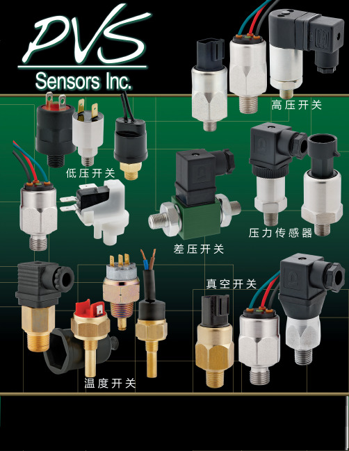
开关的保护:标准的PVS系列开关可以为绝大多数应用提供优质长寿命 的保护。开关具有防水保护,开关的浸润部分采用防腐材料构成,膜 片通常采用VITON® KAPTON®或EPDM膜片,能满足苛刻的行业应 用。外壳可选用钢铁,黄铜或不锈钢材质。
FTDATOWRFTTATINMOHWRALNOGARECELOGREUENCPTERAULILPSTOAAALNIPILOOANARNLCCANNR:ACCEEM:CSALSEEDM:ALEAS THREE PLACE
DO NOT S
PROHIBITED.
DO NOT SC
机械寿命: 1,000,000次
1 2 3
端子
公共端 常闭 常开
BPA FL CATALOG CUT AWAY A
接线
调压塞 上盖 密封圈
微动开关 顶杆
限位器 外壳
硅胶密封
调节头 弹簧 微动开关外壳
托盘 压盖 缓冲垫 膜片
BPA系列 结构示意图
上海办事处:18930221175 (江楠)Q:2244983398
3
Conv
MVA/MVF 真 空 开 关
.79 1.799.9 19.9
1.29 13.22.99 32.9
DIN型
Deutsch
TITLE:
2810 Blue RidgCe B29lv6d9.6 West Union, SC 29696
TIATALIIENN:PPTTCECEGGAARTRTAAAALLLLOODDGEGEUUATATCSCSSHSHYY
*不适用于 MPA/MVA
DE250系列高压分离连接器产品介绍说明书
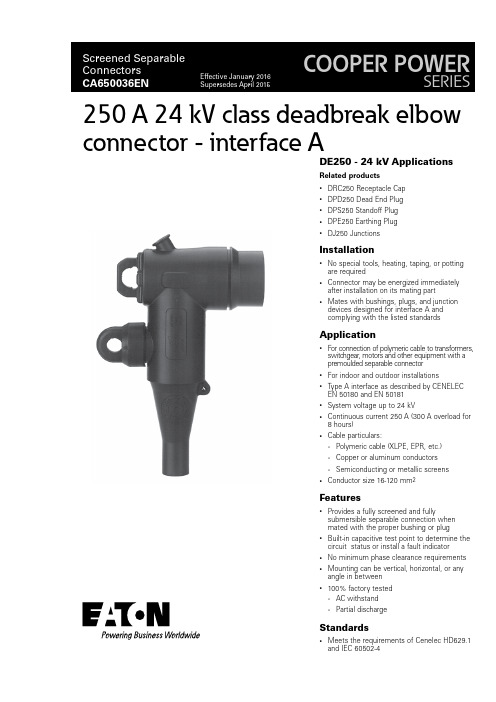
DE250 - 24 kV ApplicationsRelated products• DRC250 Receptacle Cap • DPD250 Dead End Plug • DPS250 Standoff Plug • DPE250 Earthing Plug •DJ250 JunctionsInstallation•No special tools, heating, taping, or potting are required•Connector may be energized immediately after installation on its mating part •Mates with bushings, plugs, and junction devices designed for interface A and complying with the listed standardsApplication•For connection of polymeric cable to transformers, switchgear, motors and other equipment with a premoulded separable connector • For indoor and outdoor installations •Type A interface as described by CENELEC EN 50180 and EN 50181• System voltage up to 24 kV•Continuous current 250 A (300 A overload for 8 hours)•Cable particulars:• Polymeric cable (XLPE, EPR, etc.)• Copper or aluminum conductors •Semiconducting or metallic screens•Conductor size 16-120 mm 2Features•Provides a fully screened and fullysubmersible separable connection when mated with the proper bushing or plug •Built-in capacitive test point to determine the circuit status or install a fault indicator • No minimum phase clearance requirements •Mounting can be vertical, horizontal, or any angle in between •100% factory tested • AC withstand•Partial dischargeStandards•Meets the requirements of Cenelec HD629.1and IEC 60502-4250 A 24 kV class deadbreak elbow connector - interface AQuality assurance•Our manufacturing facility is registered to ISO 9001 by third party audit• Required Production Tests •Periodic X-Ray AnalysisPackaging•Supplied in a kit with parts listed below, approximate weight 1 kgKit contents:• Elbow Housing • Conductor Contact • Pin Contact • Bail Assembly •Hex KeyThe kit also includes lubricant and installation instructions.1. Pin ContactTin-plated copper pin screws into the conductor connector with the supplied hex key.2. Internal ScreenMoulded EPDM conducting rubber screen controls electrical stress.3. InsulationMoulded EPDM insulating rubber is formulated and mixed in-house to ensure high quality.4. Pulling EyeEncapsulated stainless steel pulling eye with a detent to posi-tion the bail.5. Capacitive Test PointCapacitive test point provides means to check circuit status. A moulded EPDM conducting rubber cap provides a water-tight seal.6. Stress ReliefThe configuration of the outer screen and insulation provides cable stress relief.7. Cable EntranceThe sized opening provides an interference fit to maintain a watertight seal.8. External ScreenMoulded EPDM conducting rubber mates with the cable screen to maintain screen continuity and ensure that the assembly is at earth potential.9. Earthing EyeMoulded into the external screen for connection of an earthing wire.10. Conductor ContactInertia welded bimetallic compression connector accepts copper or aluminum conductors.11. Stainless Steel Bail (Figure 2 or 3)Secures the connector to its mating bushing or accessory.Figure 1. 250 A, 24 kV Class DE250 deadbreak elbow connector.①⑧⑨⑩⑦⑤②③④⑥Features and detailed descriptionT able 1. Electrical Ratings Maximum System Voltage (U m )24 kV Impulse125 kV AC Withstand (5 min.)54 kV Continuous Current 250 A Overload (8 hrs Max.)300 A Short Circuit Withstand, 1 sec. (rms sym.)12.5 kA2Catalog Data CA650036ENEffective January 2016250 A deadbreak elbow connector - interface A/cooperpowerseries3Catalog Data CA650036ENEffective January 2016250 A deadbreak elbow connector - interface A /cooperpowerseriesFigure 3. Optional spring loaded bail.Catalog Data CA650036ENEffective January 2016250 A deadbreak elbow connector - interface AEaton1000 Eaton Boulevard Cleveland, OH 44122United States Eaton’s Cooper Power Systems Division 2300 Badger Drive Waukesha, WI 53188/cooperpowerseries © 2016 EatonAll Rights Reserved Printed in USAPublication No. CA650036ENEaton is a registered trademark.All other trademarks are property of their respective owners.。
四川诚邦测控技术 DL系列 交流电力测功机 说明书

二、主要技术参数
1、转速测量精度:±1r/min,±1 个字 2、扭矩测量精度:±0.4%FS 3、转速控制精度:±5r/min(恒转速控制模式) 4、扭矩控制精度:±0.2%FS 5、动态响应速度:<5ms 6、变频控制方式:DTC 直接转矩控制 7、特性曲线见图 4 8、外形尺寸见图 5,表 2 9、技术数据见表 1 10、电机绝缘等级 F 11、控制柜防护等级 IP65
Page 7 of 38
DL 系列电力测功机使用说明书
性曲线落在这个区域内,均能用本机进行试验。用户在选购时可参考下列技术数据表。 表1、电力测功机技术数据表
测功机 型号 DL7.50 DL11 DL22 DL37 DL55 DL75 DL110 DL160 DL220 DL315 DL400 DL500 DL630 DL800
直接转矩控制磁场定向所用的是定子磁链,它采用离散的电压状态和六边形磁 链轨迹或近似圆形磁链轨迹的概念。只要知道定子电阻就可以把它观测出来。直接转 矩控制强调的是转矩的直接控制与效果、把转矩直接作为被控量,既直接又简化。
负载电机由变频器驱动。变频器为一台带整流/回馈单元的变频器,它由整流/
四川诚邦测控技术有限公司 网 址:
水力测功机只能在一个方向加载,同时转速低于一定值时加载性能变差;不能作为 反拖设备,在需要做发动机机械效率试验时需要另外配置拖动设备。
电涡流测功机可以双向加载,但在低速时加载性能比水力测功机还差,不能作为反 拖设备,在需要做发动机机械效率试验时需要另外配置拖动设备。
电力测功机却可以方便的实现双向加载,同时在转速到0r/min时依然可以提供足够 的加载能力;其加载特性为零转速至额定转速为恒扭矩特性,额定转速至最高转速为恒
堤纳(Trane)单包装可转换气电炉空气条件器系列说明书

Product DataSingle Packaged Gas/Electric15SEER Convertible,2–5Ton4YCY5024A1060A Array 4YCY5030A1070A4YCY5036A1070A4YCY5036A1090A4YCY5042A1090A4YCY5048A1090A4YCY5048A1115A4YCY5060A1115AN o t e:“Graphics in this document are for representation only.Actual model maydiffer in appearance.”June202022-1913-1D-E NSingle Packaged ConvertibleGas/Electric SystemsTrane offers a complete family of packaged gas/electric heating and cooling systems,designed toprovide the unbeatable combination of energy efficiency and lower operating costs.In warmweather,the package gas/electric system functions as an all-electric,high efficiency airconditioner.In cold weather,it operates as a natural gas or propane gas furnace,offering thebest of both energy worlds.B e c a u s e c o o l i n g a n d h e a t i n g f u n c t i o n s a r e a l l c o n t a i n e d i n a s i n g l e c a b i n e t,a s i n g l ep a c k a g e d c o n v e r t i b l e g a s/e l e c t r i c s y s t e m i s e a s y t o i n s t a l l a n d s e r v i c e.It can be flush mounted beside your home at ground level or placed on the roof for horizontal ordownflow installation.When connected to an optional American Standard thermostat control,and air distribution ducts,you have a highly efficient,total home comfort system.S i n g l e P a c k a g e d C o n v e r t i b l e G a s/E l e c t r i c S y s t e m s a r e u n m a t c h e d i n q u a l i t y a n dr e l i a b i l i t y.All major components on these products,including the compressor,have been designed andmanufactured for maximum service.Every compressor is designed and manufactured toexacting specifications.Each design is life tested in extreme environments to ensure reliable andlong lasting operation in normal applications.Each compressor has internal motor protection foradded reliability.S i n g l e P a c k a g e d C o n v e r t i b l e G a s/E l e c t r i c S y s t e m s p r o v i d e b e t t e r p e r f o r m a n c e.Our single packaged cooling/heating units offer cooling/heating efficiencies that are unmatchedin the industry and provide you with a product far superior in performance than the competition.Optional Equipment Listing(a)Must use internal filter frame when economizer or fresh air kit is used.(b)It is the responsibility of the installing dealer to properly size the ductwork for each specific application.(c)Dry bulb control standard with economizer.(d)Downflow only.Product SpecificationsP r o d u c t S p e c i f i c a t i o n s(a)Rated in accordance with AHRI Standard210/240.AHRI standard rating conditions are:80D.B.67W.B.entering air to indoor coil.95D.B.entering air tooutdoor coil.(b)Sound Power values are not adjusted for AHRI270–95tonal corrections.(c)Ratings shown are for elevations up to2000ft.For higher elevations reduce ratings at a rate of4%per1000ft.elevation.(d)Convertible to LPG.(e)Convertible to LPG.(f)This value is approximate.For more precise value,see Unit Nameplate.(g)Standard Air—Dry Coil—Outdoor.(h)Based on ernment Standard Tests.(i)Filters must be installed in return air stream.Square footages listed are based on300f.p.m.face velocity.If permanent filters are used size permanufacturer’s recommendation with a clean resistance of0.05”W.C.P r o d u c t S p e c i f i c a t i o n sP r o d u c t S p e c i f i c a t i o n s(a)Rated in accordance with AHRI Standard210/240.AHRI standard rating conditions are:80D.B.67W.B.entering air to indoor coil.95D.B.entering air tooutdoor coil.(b)Sound Power values are not adjusted for AHRI270–95tonal corrections.(c)Ratings shown are for elevations up to2000ft.For higher elevations reduce ratings at a rate of4%per1000ft.elevation.(d)Convertible to LPG.(e)Convertible to LPG.(f)This value is approximate.For more precise value,see Unit Nameplate.(g)Standard Air—Dry Coil—Outdoor.(h)Based on ernment Standard Tests.(i)Filters must be installed in return air stream.Square footages listed are based on300f.p.m.face velocity.If permanent filters are used size permanufacturer’s recommendation with a clean resistance of0.05”W.C.Indoor Fan PerformanceTable1.Horizontal AirflowTable2.Down AirflowTable3.AIRFLOW WITH AUXILIARY HEAT(CFM)Horizontal or Downflow from.2to.6”wg.Table4.Horizontal AirflowI n d o o r F a n P e r f o r m a n c e Table5.Down AirflowTable6.AIRFLOW WITH AUXILIARY HEAT(CFM)Horizontal or Downflow from.2to.6”wg.Table7.Horizontal AirflowTable8.Down AirflowTable9.AIRFLOW WITH AUXILIARY HEAT(CFM)Horizontal or Downflow from.2to.6”wg.I n d o o r F a n P e r f o r m a n c eTable10.Horizontal AirflowTable11.Down AirflowTable12.AIRFLOW WITH AUXILIARY HEAT(CFM)Horizontal or Downflow from.2to.6”wg.Table13.Horizontal AirflowI n d o o r F a n P e r f o r m a n c e Table14.Down AirflowTable15.AIRFLOW WITH AUXILIARY HEAT(CFM)Horizontal or Downflow from.2to.6”wg.Table16.Horizontal AirflowTable17.Down AirflowTable18.AIRFLOW WITH AUXILIARY HEAT(CFM)Horizontal or Downflow from.2to.6”wg.Field WiringFigure 1.4YCY5024–042Field WiringDiagramC 757192i2B G Y W1W2R COMMONFAN COMPRESSORHEAT FIRST STAGE HEAT SECOND STAGE 24VUNIT CONTROL BOXGROUND WIRE3 PH POWER UNIT NOTE 11 PH POWERB G Y W1W2R COMMONFAN COMPRESSORHEAT FIRST STAGE HEAT SECOND STAGE 24VBG Y W1W2R(GR) (CONSTANT CIRCULATION)(WH)(WH)(GR) (CONSTANT CIRCULATION)(WH)(WH)(GR)(WH)(WH)Figure 2.4YCY5048–060Field WiringDiagramF i e l d W i r i n gWiringFigure3.Wiring Diagram-4YCY5024–5042W i r i n gFigure 4.Wiring Diagram -4YCY5036W i r i n gW i r i n gFigure 5.Wiring Diagram -4YCY5048W i r i n gW i r i n gFigure 6.Wiring Diagram -4YCY5060W i r i n gW i r i n gFull Perimeter Roof Mounting CurbFigure7. 2.0—3.0Ton ModelsBAYCURB050A Full Perimeter Roof Mounting CurbFigure 8. 3.5—5.0TonModelsBAYCURB051A Full Perimeter Roof Mounting CurbF u l l P e r i m e t e r R o o f M o u n t i n g C u r bOptional Equipment—Filter RackFigure9.BAYFLTR101Filter Rack(2.0–3.0Ton Models)BAYFLTR201(3.5–5.0Ton Models)(Mounts in Filter/Coil Section)Figure10.BAYACCDOR1A Hinged Filter Access Door(2.0–3.0Ton Models)BAYACCDOR2A(3.5–5.0Ton Models)Replaces Filter/Coil Access PanelNote:The drawings on this page are prepared by the manufacturer in order to provide detail regarding job layout only.These drawings are not intended to be used as a basis to construct,build or modify the items depicted in the drawings.The manufacturer is not responsible for the unauthorized use of these drawings and expressly disclaims any liability for damages resulting from such unauthorized use.Optional Equipment —EconomizerTable 19.BAYECON101,102A Down Discharge Economizer and Rain Hood (Mounts Over Horizontal Return Air Opening)Table 20.BAYCON200,201A Horizontal Economizer and Rain HoodEconomizerGaskets (2)Rain HoodMixed Air SensorDuctAB CDEModels A B C D —3.0Ton 22”20”16–7/8”15–11/16”—5.0Ton26”22–21/32”19”17–11/16”Note:The drawings on this page are prepared by the manufacturer in order to provide detail regarding job layout only.These drawings are notintended to be used as a basis to construct,build or modify the items depicted in the drawings.The manufacturer is not responsible for the unauthorized use of these drawings and expressly disclaims any liability for damages resulting from such unauthorized use.Optional Equipment—Outside Air DamperTable21.BAYOSAH001and002ATable22.BAYDMPR101and102A,25%Motorized Outside Air Damper(Mounts Over Horizontal Return Air Opening)Note:The drawings on this page are prepared by the manufacturer in order to provide detail regarding job layout only.These drawings are not intended to be used as a basis to construct,build or modify the items depicted in the drawings.The manufacturer is not responsible for the unauthorized use of these drawings and expressly disclaims any liability for damages resulting from such unauthorized use.Outline DrawingFigure11. 2.0—3.0Ton ModelsDWG: D673947G01revB_pg1Figure 12.2.0—3.0TonModelsDWG: D673947G01_PG2O u t l i n e D r a w i n gFigure 13.3.5—5.0TonModelsDWG: D673948G01_pg1O u t l i n e D r a w i n gFigure 14.3.5—5.0TonModelsDWG: D673948G01revB_pg2O u t l i n e D r a w i n gN o t e s 22-1913-1D-EN31Trane-by Trane Technologies(NYSE:TT),a global innovator-creates comfortable,energy efficient indoor environments for commercial and residential applications.For more information,please visit or .The AHRI Certified mark indicates Trane U.S.Inc.participation in the AHRI Certification program.For verification of individual certified products,go to ahridirectory. org.Trane has a policy of continuous data improvement and it reserves the right to change design and specifications without notice.We are committed to using environmentally conscious print practices.22-1913-1D-EN01Jun2020Supersedes22-1913-1C-EN(July2019)©2020Trane。
FESTO标准化双向气泵DSBG系列产品介绍说明书
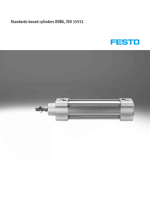
Standards-based cylinders DSBG, ISO 155522d I nternet: /catalogue/...Subject to change – 2023/08Standards-based cylinders DSBG, ISO 15552CharacteristicsAt a glance• Standards-based cylinders to ISO 15552 (corresponds to the withdrawn standards ISO 6431, DIN ISO 6431, VDMA 24 562, NF E 49 003.1 and UNI 10290)• Sturdy tie rod design • Double-acting• For contactless position sensing • Optionally with protection against rotation• EX4: for use in potentially explosive areas• Extensive range of accessories makes it possible to install the cylinder virtually anywhere• Three types of cushioning available:– Elastic cushioning: elastic cush -ioning rings/plates at both ends – PPS cushioning: pneumatic cush -ioning, self-adjusting at both ends– PPV cushioning: pneumatic cush -ioning, adjustable at both ends• The variants can be configured according to individual needs using a modular product system• Wide range of variants provides high level of flexibilityDSBG-...-P2 – With bellows kit DADB, to ISO 15552The bellows protects the piston rod, the seal and the bearing from the ef-fects of a wide range of media, which has a positive impact on the service life of these components.The bellows kit is a leak-free system. To prevent unwanted media from being drawn in, the supply and exhaust air for the kit must be ducted via a pressure compensation hole in the connection part [1].The kit protects the piston rod, seal and bearing against a wide variety of media, for example:• Dust• Chippings • Oil • Grease • FuelOrdering the bellows kitAn extended piston rod is absolutely essential if a bellows kit is to be used.The bellows kit can be ordered via the modular product system or as an ac-cessory. The following must be noted in this case:Ordering via the modular product system:The bellows kit is supplied mounted on the bearing cap using characteristic P2. The required piston rod extension is automatically taken into considera -tion. This means that there is no need to specify a value for characteristic ...E.Ordering as an accessory:If the bellows kit is ordered as an accessory, the required value a page 39 must be entered for characteristic ...E in the modular product system.Position sensing/force controlWith position transmitter SMAT, SDAT a page 43With proportional-pressure regulator VPPMAnalogue position feedback possible • Analogue output –0 ... 10 VInfinite adjustment of the gripping force possible• Setpoint value input – 0 ... 10 V – 4 ... 20 mAStandards-based cylinders DSBG, ISO 15552 Characteristics3 2023/08 – Subject to change d I nternet: /catalogue/...Standards-based cylinders DSBG, ISO 15552Product range overview4d I nternet: /catalogue/...Subject to change – 2023/08Standards-based cylinders DSBG, ISO 15552 Product range overview5 2023/08 – Subject to change d I nternet: /catalogue/...Standards-based cylinders DSBG, ISO 15552Peripherals overview6d I nternet: /catalogue/...Subject to change – 2023/08Standards-based cylinders DSBG, ISO 15552 Peripherals overview7 2023/08 – Subject to change d I nternet: /catalogue/...Standards-based cylinders DSBG, ISO 15552Type codes8d I nternet: /catalogue/...Subject to change – 2023/0892023/08 – Subject to change d I nternet: /catalogue/...Standards-based cylinders DSBG, ISO 15552Data sheetFunctionElastic cushioningPPS cushioningN- Diameter32 ... 125 mm-T- Stroke length1 ... 2800 mm-É-6380100G3/8G3/8G1/2Standards-based cylinders DSBG, ISO 15552Data sheet1)Values apply only for strokes š 500 mm and after 10 double strokes.In combination with cushioning PPV/PPS, the specifications only apply outside the cushioning range2)Note operating range of proximity switches.3)Corrosion resistance class CRC 2 to Festo standard FN 940070Moderate corrosion stress. Indoor applications in which condensation can occur. External visible parts with primarily decorative surface requirements which are in direct contact with a normal industrial environment.4)Corrosion resistance class CRC 3 to Festo standard FN 940070High corrosion stress. Outdoor exposure under moderate corrosive conditions. Externally visible parts with primarily functional surface requirements which are in direct contact with a normal industrial environment.10d I nternet: /catalogue/...Subject to change – 2023/081) Note the ATEX certification of the accessories.Permissible impact velocity:VV Perm. impact velocity E Max. impact energy m1 Moving mass (drive)m2 Moving payloadMaximum permissible mass:212Em m v²×=−MaterialsSectional view 25316497810Max. transverse load Fq as a function of stroke length l Horizontal installationVertical installationl [mm]F q [N ]40080012001600200011010010002000Diameter 32Diameter 40Diameter 50/63Diameter 80/100Diameter 125l [mm]F q [N ]50010001500200011010010002000H- -NoteNo transverse loads are permitted incombination with characteristicDSBG-...-L1.Max. torque = 1500 Nmm/max. stroke = 500 mm Max. torque = 3000 Nmm/max. stroke = 600 mmExamples for piston diameter 32 mmExample 1:Stroke length l = 150 mm Result: permissible Transverse load Fq = 9.5 N Lever arm s = 84 mm Example 2:Transverse load Fq = 40 NResult: permissibleStroke length l = 28 mmLever arm s = 20 mmExample 3:Stroke length l = 150 mmLever arm s = 100 mmM = max. torques = lever armResult: permissibleFq= 8 N ‹ Fq max. = 9.5 NdFq1) Threads with smaller nominal diameter than in the basic version can generally not withstand such high loads. If necessary, the screw connection must be engineered.1) The dimension corresponds to the E value (piston rod extension) of the driveH--NoteOther variants in the modularproduct system a page 24H--NoteOther variants in the modularproduct system a page 24H--NoteOther variants in the modularproduct system a page 24[1] Q Not with L, U, N3, T3, T4, P2, A2, A3, A6Only up to stroke of 1500 mm[2] L, U Not with T, R3, T1, T3, T4, P2, A2, A3, A6, EX4[3] L1 Not with T, PPV, R3, T1, T3, T4, P2, A2, A3, A6, EX4[4] F Not with N3, ...L, M...[5] PPS Not with T1, T3, T4[6] R3 Not with A2, A6, (V)[7] T1, T3, T4 Not with P2, A2, A3, EX4H--NoteIf characteristic L is used in combina-tion with transverse loads or strokes of above 500 mm, suitable measures must be taken to support the piston rod.The operating pressure(a page 10) is applicable for strokes up to 500 mm.H--NoteIf characteristic L1 is used in combina-tion with strokes of above 500 mm, suitable measures must be taken to support the piston rod.The operating pressure(a page 10) is applicable for strokes up to 500 mm.[8] P2 Not with N3, A2, A3, A6, EX4Only for strokes 10 ... 500 mm[9] EX4 Not with T1, T3, T4, P2, A3, A6, ...LB2, ...LB3[10] ...E, ...L Only up to stroke of 2000 mm.Not with N3[11] M..., LB... Not with N3H--NoteThe piston rod extension for the bel-lows is automatically taken into con-sideration when characteristic P2 is selected. This means that there is no need to specify a value for character-istic ...E.H--NoteWhen characteristic ...E is selected incombination with characteristic P2,the part of the piston rod extension...E is not covered by the bellows.H--NoteWhen characteristic P2 is selected incombination with characteristic T(through piston rod), the bellows ismounted at one end only.H--NoteIf a thread smaller than the stand-ard thread is selected for character-istic M... (piston rod thread), this may reduce the load capacity.H--NoteWhen characteristic M... is selected, the piston rod nut is not included.Foot mounting HNC/CRHNC Material:HNC: galvanised steelCRHNC: high-alloy steelFree of copper and PTFE1)Corrosion resistance class CRC 2 to Festo standard FN 940070Moderate corrosion stress. Indoor applications in which condensation can occur. External visible parts with primarily decorative surface requirements which are in direct contact with a normal industrial environment.Corrosion resistance class CRC 4 to Festo standard FN 940070Particularly high corrosion stress. Outdoor exposure under extreme corrosive conditions. Parts exposed to aggressive media, e.g. in the chemical or food industries. Such applications may need to be safeguarded by special tests(d also FN 940082), using appropriate media.2)Suitable for ATEXFlange mounting FNC/CRFNG Material:FNC: galvanised steelCRFNG: high-alloy steelFree of copper and PTFERoHS-compliant1)Corrosion resistance class CRC 1 to Festo standard FN 940070Low corrosion stress. Dry internal application or transport and storage protection. Also applies to parts behind coverings, in the non-visible interior area, and parts which are covered in the application (e.g. drive trunnions).Corrosion resistance class CRC 4 to Festo standard FN 940070Particularly high corrosion stress. Outdoor exposure under extreme corrosive conditions. Parts exposed to aggressive media, e.g. in the chemical or food industries. Such applications may need to be safeguarded by special tests(d also FN 940082), using appropriate media.2)Suitable for ATEXTrunnion flange ZNCF/CRZNG Material:ZNCF: stainless steel castingCRZNG: electropolished stainless steelcastingFree of copper and PTFERoHS-compliant1)Corrosion resistance class CRC 2 to Festo standard FN 940070Moderate corrosion stress. Indoor applications in which condensation can occur. External visible parts with primarily decorative surface requirements which are in direct contact with a normal industrial environment.Corrosion resistance class CRC 4 to Festo standard FN 940070Particularly high corrosion stress. Outdoor exposure under extreme corrosive conditions. Parts exposed to aggressive media, e.g. in the chemical or food industries. Such applications may need to be safeguarded by special tests(d also FN 940082), using appropriate media.2)Suitable for ATEXTrunnion support LNZG Material:Trunnion support: anodisedaluminiumPlain bearing: plasticFree of copper and PTFERoHS-compliant1)Corrosion resistance class CRC 2 to Festo standard FN 940070Moderate corrosion stress. Indoor applications in which condensation can occur. External visible parts with primarily decorative surface requirements which are in direct contact with a normal industrial environment. Trunnion support CRLNZG Material:High-alloy steelFree of copper and PTFERoHS-compliant1)Corrosion resistance class CRC 4 to Festo standard FN 940070Particularly high corrosion stress. Outdoor exposure under extreme corrosive conditions. Parts exposed to aggressive media, e.g. in the chemical or food industries. Such applications may need to be safeguarded by special tests(d also FN 940082), using appropriate media.Swivel flange SNC Material:Die-cast aluminiumRoHS-compliant1)Corrosion resistance class CRC 1 to Festo standard FN 940070Low corrosion stress. Dry internal application or transport and storage protection. Also applies to parts behind coverings, in the non-visible interior area, and parts which are covered in the application (e.g. drive trunnions).2)Suitable for ATEXSwivel flange SNCB/SNCB-...-R3 Material:SNCB: die-cast aluminiumSNCB-…-R3: die-cast aluminium withprotective coatingFree of copper and PTFERoHS-compliant1)Corrosion resistance class CRC 1 to Festo standard FN 940070Low corrosion stress. Dry internal application or transport and storage protection. Also applies to parts behind coverings, in the non-visible interior area, and parts which are covered in the application (e.g. drive trunnions).Corrosion resistance class CRC 3 to Festo standard FN 940070High corrosion stress. Outdoor exposure under moderate corrosive conditions. Externally visible parts with primarily functional surface requirements which are in direct contact with a normal industrial environment.Swivel flange Material:SNCS 32 ... 50:Die-cast aluminiumSNCS 63 ... 125:Wrought aluminium alloyCRSNCS 32 ... 80:High-alloy stainless steelSNCS-...-R3 100 ... 125:Wrought aluminium alloy withprotective coatingRoHS-compliant1)Corrosion resistance class CRC 1 to Festo standard FN 940070Low corrosion stress. Dry internal application or transport and storage protection. Also applies to parts behind coverings, in the non-visible interior area, and parts which are covered in the application (e.g. drive trunnions).Corrosion resistance class CRC 2 to Festo standard FN 940070Moderate corrosion stress. Indoor applications in which condensation can occur. External visible parts with primarily decorative surface requirements which are in direct contact with a normal industrial environment.Corrosion resistance class CRC 3 to Festo standard FN 940070High corrosion stress. Outdoor exposure under moderate corrosive conditions. Externally visible parts with primarily functional surface requirements which are in direct contact with a normal industrial environment.Corrosion resistance class CRC 4 to Festo standard FN 940070Particularly high corrosion stress. Outdoor exposure under extreme corrosive conditions. Parts exposed to aggressive media, e.g. in the chemical or food industries. Such applications may need to be safeguarded by special tests (d also FN 940082), using appropriate media.Swivel flange SNCL Material:Die-cast aluminiumFree of copper and PTFERoHS-compliant1)Corrosion resistance class CRC 1 to Festo standard FN 940070Low corrosion stress. Dry internal application or transport and storage protection. Also applies to parts behind coverings, in the non-visible interior area, and parts which are covered in the application (e.g. drive trunnions).1) Suitable for ATEX1) Suitable for ATEX1) Suitable for ATEXBellows kit DADB 1)In combination with the bellows kit DADB2)Note operating range of proximity switches and cylinder3)Corrosion resistance class CRC 3 to Festo standard FN 940070High corrosion stress. Outdoor exposure under moderate corrosive conditions. Externally visible parts with primarily functional surface requirements which are in direct contact with a normal industrial environment.MaterialsSectional view15234Travel speed v as a function of tubing length lThe bellows kit is a leak-free system. To prevent unwanted media from being drawn in, the supply and exhaust air for the kit must be ducted via a pressurecompensation hole in the connection part [1].The pressure generated in the bellows kit by the positioning motion is primar -ily defined by the travel speed and the tubing length. The recommended tub -ing length based on the travel speed of the drive can be read from the graph.AdvancingRetractingl [m]v [m /s ]123456789100.20.40.60.811.2Diameter 32/50/63Diameter 40Diameter 80/100l [m]v [m /s ]1234567891000.20.40.60.811.2Diameter 32Diameter 40Diameter 50/63Diameter 80/1001) The dimension corresponds to the E value (piston rod extension) of the driveOrdering data – Bellows kitAn extended piston rod (order code E) is absolutely essential when using a bellows kit a Ordering data – Modular product system.The necessary dimension for ordercode E as a function of piston diameterand cylinder stroke as well as the cor-responding bellows kit is indicated inthe table below:Order example:Selected standards-based cylinder:DSBG-32-320-PPV-A-...The dimension for the corresponding E value (see table):112 mmComplete order reference for standards-based cylinder:DSBG-32-320-PPV-A- (112)The corresponding bellows kit:DADB-V6-32-S301-350Multi-position kit DPNC Material:Flange: wrought aluminium alloyThreaded pins, hex nuts: galvanised steelConnecting two cylinders with identical piston diameters to form a three or four-position cylinder A three or four-position cylinder con-sists of two separate cylinders whose piston rods advance in opposing directions.This means that depending on the ac-tuation and stroke pattern, this type of cylinder can assume up to four posi-tions. In each case the cylinder is moved preciselyagainst a stop. Note that when one end of the piston rod is fixed, the cylinder barrelexecutes the movement. The line connections to the cylinder must be flexible.To achieve 3 positionsTo achieve 4 positionsTwo cylinders with identical stroke length must be connected together.Two cylinders with different stroke lengths must be connected together.Standards-based cylinders DSBG, ISO 15552 Accessories1) Suitable for ATEX41 2023/08 – Subject to change d I nternet: /catalogue/...Standards-based cylinders DSBG, ISO 15552Accessories42d I nternet: /catalogue/...Subject to change – 2023/08Standards-based cylinders DSBG, ISO 15552Accessories1)Corrosion resistance class CRC 4 to Festo standard FN 940070Particularly high corrosion stress. Outdoor exposure under extreme corrosive conditions. Parts exposed to aggressive media, e.g. in the chemical or food industries. Such applications may need to be safeguarded by special tests(d also FN 940082), using appropriate media.Position transmitterThe position transmitter continuously senses the position of the piston. It has an analogue output with an output signal in proportion to the piston position.43 2023/08 – Subject to change d I nternet: /catalogue/...Standards-based cylinders DSBG, ISO 15552Accessories44d I nternet: /catalogue/...Subject to change – 2023/08Festo - Your Partner in AutomationConnect with us/socialmedia 1Festo Inc.2Festo Pneumatic 3Festo Corporation 4Regional Service Center 5300 Explorer DriveMississauga, ON L4W 5G4CanadaAv. Ceylán 3,Col. Tequesquináhuac 54020 Tlalnepantla, Estado de México1377 Motor Parkway Suite 310Islandia, NY 117497777 Columbia Road Mason, OH 45040Festo Customer Interaction CenterTel:187****3786Fax:187****3786Email:*****************************Multinational Contact Center 01 800 337 8669***********************Festo Customer Interaction Center180****3786180****3786*****************************S u b j e c t t o c h a n g e。
