富士通继电器ftr-k1技术资料
光继电器规格-Toshiba

这意味着开关(SW)工作时没有电压加入。 因此SW闭合时没有电流流过,然后输出电 源信号。
机械继电器使用在热开关情况时寿命较短。 只要保持不超过最大额定值,光继电器可以使用在热开关或冷开关情况。
*机械继电器的情况下,由于热开关施加电压,电流在触点闭合瞬间流动,触点容易磨损。此外,当开关断开时,电流中断会 产生电弧,因此寿命缩短。
SSR (固态继电器)
・ 使用半导体光敏双向晶闸管、光敏晶体管或光敏晶闸管作为输出器件 ・ 光敏双向晶闸管、光敏晶闸管输出器件限于交流负载
注:这一分类可能与目录型分销商(例如得捷电子/贸泽电子等)的实际分类不同。我们建议直接用产品名进 行搜索。
光继电器结构
SO6封装
3.7×7.0×2.1 mm
框架类型
trin是输入波形上升时间; trout是继电器转换后的输出波形上升时间。 ERT值越低,输出信号越接近原始输入波形。
术语3
术语
推荐工作条件 电源电压 推荐工作条件 LED输入正向电流 通态电流 工作温度
符号
--VDD IF IO Topr
描述
为了达到器件的预期性能,而考虑了绝对最大规格降额的设计指南。每条建议都是独 立考虑,且未考虑多种使用条件。 考虑了最大规格降额的推荐电源电压。 在交流的情况下,其是峰值电压。
考虑了最大规格降额的推荐LED正向电流。
设计考虑
36 光继电器失效模式 37 IF设计考虑 39 推荐LED驱动电路示例 40 输入侧过压/过流 42 输入侧设计考虑不足 47 输出侧过压/过流 54 输出侧设计考虑不足
光继电器的优势
8 光继电器与机械继电器特性比较 9 安装面积小型化 10 高可靠性 11 低输入电流/低电压驱动 12 优异的开关特性 13 热开关支持 14 与机械继电器比较
继电器手册——精选推荐

控制继电器工程技术人员培训教材目录第一章小型电磁继电器 6.5.2 使用温度范围1.前言 6.6 动作时间和释放时间2.继电器的结构及动作原理 6.7 环境特征3.继电器与半导体开关的比较 6.7.1 温湿度特性4.继电器的种类 6.7.2 耐冲击和振动特性4.1 继电器分类 6.8 故障4.2 有悠久历史的绞链式继电器 6.9 寿命4.2.1 通讯用继电器 6.9.1 机械寿命试验4.2.2 一般产业用继电器 6.9.2 电气寿命试验4.3 近代的绞链式继电器 6.10 工业规格和安全规格4.3.1 PCB印刷线路板继电器 6.10.1 工业规格4.3.2 超小型继电器的形状和尺寸 6.10.2 安全规格4.3.3 超小型继电器的端子形状和端子配置4.3.4 防止焊剂渗入的超小型继电器第二章继电器的选择和使用方法4.3.5 高灵敏超小型继电器 1 前言4.3.6 自保持型继电器 2 继电器的选择4.3.7 高频继电器 2.1 继电器的选择原则4.4 舌簧继电器 2.2 关于继电器的接点5继电器的结构部件及其使用材料 2.2.1 根据接点负载的种类确定继 5.1 接点电器形式5.1.1 接点形状 2.2.2 根据接点负载电流大小来5.1.2 多层接点选择继电器5.1.3 接点材料 2.2.3 对接点的开闭频度要特别注意 5.2 接点簧片材料5.3 磁路材料 2.3 关于激磁线圈5,4 绝缘材料 2.3.1 交流驱动和直流驱动6绞链式继电器的主要性能和特性 2.3.2 特殊的驱动回路6.1 接触电阻 2.3.3 线圈功耗和线圈电阻6.1.1 概述 2.3.4 动作电压和释放电压6.1.2 接触面的污染和接触电阻 2.3.5 热线圈和冷线圈6.1.3 接点的净化 2.3.6 环境温度和线圈允许电压6.1.4 接触压力及其接点摺动和接触电阻5. 6.1.5 塑料密封和接触电阻 2.4 动作时间和释放时间6.1.6 双子接点可以提高接触可靠性 2.5 介质耐压和绝缘电阻6.1.7 电压、电流和接触电阻 2.5.1 继电器特征6.1.8 接点消耗和接触电阻 2.5.2 工频与介质耐压6.1.9 接触电阻的测量方法 2.5.3 耐浪涌电压6.2 接点熔着 2.5.4 绝缘电阻6.3 介质耐电压和绝缘电阻 2.6 环境关系6.4 动作电压和释放电压 2.6.1 周围温湿度6.5 继电器温升和使用温度范围 2.6.2 周围环境气氛6.5.1 温升 2.6.3 冲击和振动2.7 关于安装2.7.1 外形尺寸2.7.2 继电器安装和引出端接线2.7.3 印刷线路板用超小型继电器的外形尺寸和结构2.7.4 印刷线路板用超小型继电器的安装2.8 故障率和寿命3 继电器的最佳使用方法3.1 硅及其化合物是继电器大敌3.2 外界强磁场会影响继电器的动作电压和释放电压3.3 负载的接线方法3.4 继电器安装的注意事项3.5 用晶体管来驱动继电器3.5.1 驱动回路3.5.2 晶体管选择3.5.3 防止反电压3.5.4 用晶体管驱动继电器的注意事项 3.6 接点开闭时要注意交流负载相位3.7 闭锁继电器的使用3.7.1 闭锁驱动回路的实例3.7.2 闭锁驱动回路接线时的注意事项 3.7.3 其他使用方面的注意事项3.8 印刷线路板实装3.8.1 向印刷线路板上安装继电器时的布线设计3.8.2 手工焊接时的注意事项3.8.3 自动焊接时的注意事项3.8.4 清洗工程的注意事项第一章小型电磁继电器1 前言通俗一点说继电器就是一个输出回路的开与关是由输入回路的信号状态来确定的电子元件。
富士通继电器A12W-K
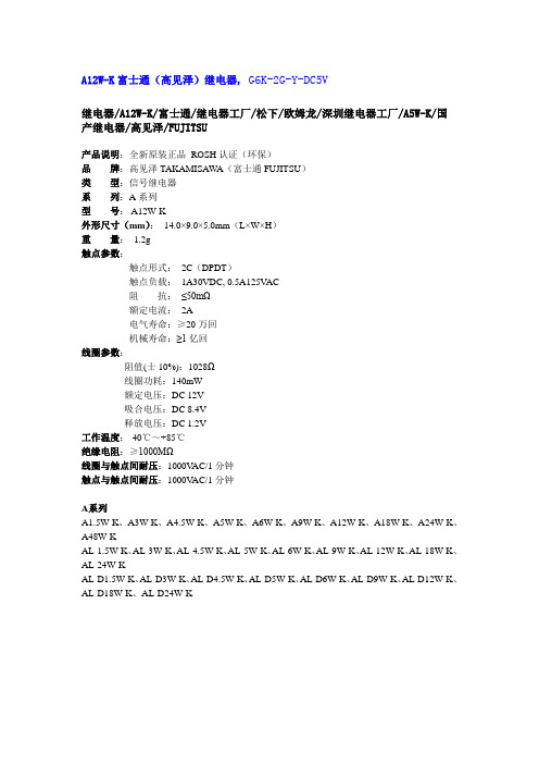
A12W-K富士通(高见泽)继电器, G6K-2G-Y-DC5V
继电器/A12W-K/富士通/继电器工厂/松下/欧姆龙/深圳继电器工厂/A5W-K/国
产继电器/高见泽/FUJITSU
产品说明:全新原装正品ROSH认证(环保)
品牌:高见泽TAKAMISAWA(富士通FUJITSU)
类型:信号继电器
系列:A系列
型号: A12W-K
外形尺寸(mm):14.0×9.0×5.0mm(L×W×H)
重量:1.2g
触点参数:
触点形式:2C(DPDT)
触点负载:1A30VDC, 0.5A125V AC
阻抗:≤50mΩ
额定电流:2A
电气寿命:≥20万回
机械寿命:≥1亿回
线圈参数:
阻值(士10%):1028Ω
线圈功耗:140mW
额定电压:DC 12V
吸合电压:DC 8.4V
释放电压:DC 1.2V
工作温度:-40℃~+85℃
绝缘电阻:≥1000MΩ
线圈与触点间耐压:1000V AC/1分钟
触点与触点间耐压:1000V AC/1分钟
A系列
A1.5W-K、A3W-K、A4.5W-K、A5W-K、A6W-K、A9W-K、A12W-K、A18W-K、A24W-K、A48W-K
AL-1.5W-K、AL-3W-K、AL-4.5W-K、AL-5W-K、AL-6W-K、AL-9W-K、AL-12W-K、AL-18W-K、AL-24W-K
AL-D1.5W-K、AL-D3W-K、AL-D4.5W-K、AL-D5W-K、AL-D6W-K、AL-D9W-K、AL-D12W-K、AL-D18W-K、AL-D24W-K。
富士通继电器A5W-K
5 VDC
178Ω
A- 6 W-K
6 VDC
257Ω
A- 9 W-K
9 VDC
579Ω
A-12 W-K
12 VDC
1,028Ω
A-18 W-K
18 VDC
1,620Ω
A-24 W-K
24 VDC
2,880Ω
A-48 W-K
48 VDC
7,680Ω
Note: *1 Specified values are subject to pulse wave voltage. All values in the table are measured at 20°C.
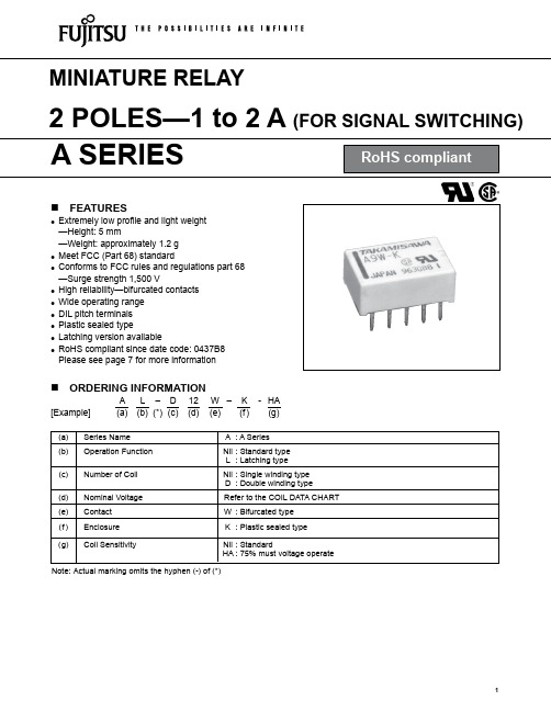
MINIATURE RELAY
2 POLES—1 to 2 A (FOR SIGNAL SWITCHING)
A SERIES
RoHS compliant
n FEATURES
l Extremely low profile and light weight —Height: 5 mm —Weight: approximately 1.2 g
1
A SERIES
n COIL DATA CHART
MODEL
Nominal voltage
Coil resistance (±10%)
A-1.5W-K
1.5 VDC
16.1Ω
A- 3 W-K
3 VDC
64.3Ω
Standard Type
A-4.5W-K
4.5 VDC
145Ω
A- 5 W-K
140 to 300 mW 100 to 150 mW 200 to 300 mW
Operate Power (at 20°C)
富士通继电器
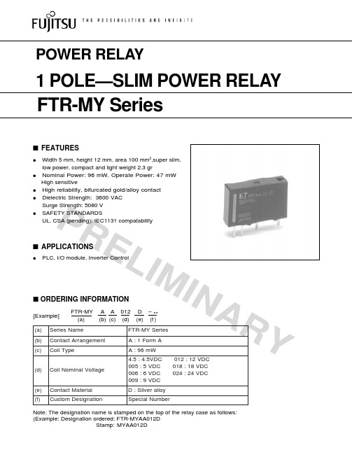
P RE LI MI NA RYs ORDERING INFORMATIONFTR-MY A A 012 D – **[Example](a)(b)(c)(d) (e) (f )s FEATURESqWidth 5 mm, height 12 mm, area 100 mm 2,super slim,low power, compact and light weight 2.3 grqNominal Power: 96 mW, Operate Power: 47 mW High sensitiveq High reliability, bifurcated gold/alloy contact qDielectric Strength: 3600 VAC Surge Strength: 5080 V qSAFETY STANDARDSUL, CSA (pending), IEC1131 compatabilitys APPLICATIONSqPLC, I/O module, Inverter Control)a (e m a N s e i r e S s e i r e S Y M -R T F )b (t n e m e g n a r r A t c a t n o C A m r o F 1:A )c (ep y T l i o C W m 69:A )d (e g a t l o V l a n i m o N l i o C C D V 21:210C D V 5.4:5.4C D V 81:810C D V 5:500CD V 42:420C D V 6:600C D V 9:900)e (l a i r e t a M t c a t n o C y o l l a r e v l i S :D )f (no i t a n g i s e D m o t s u C re b m u N l a i c e p S Note: The designation name is stamped on the top of the relay case as follows:(Example: Designation ordered: FTR-MYAA012DStamp:MYAA012D2P R EL I MI N A R Ys SPECIFICATIONS*1 Minimum switching loads mentioned above are reference values. Please perform the confirmation test with theactual load before production since reference values may vary according to switching frequencies, environmental conditions and expected reliability levels.m e t I se i r e S Y M -R T F tc a t n o C t n e m e g n a r r A Am r o F 1la i r e t a M y o l l a r e v l i S -y o l l a r e v l i s d i a l r e v o d l o G )l a i t i n i (e c n a t s i s e R m 03m u m i x a M Ω)C D V 6A 1t a ()e v i t s i s e r (g n i t a R A 3,C D V 03/C A V 052tn e r r u C g n i y r r a C m u m i x a M A5gn i t a R g n i h c t i w S m u m i x a M W 09/A V 057e g a t l o V g n i h c t i w S m u m i x a M C D V 521,C A V 052t n e r r u C g n i h c t i w S m u m i x a M A5d a o L g n i h c t i w S m u m i x a M 1*Am 1,C D V 5li o C )C ˚02t a (r e w o P l a n i m o N W m 69)C ˚02t a (r e w o P e t a r e p O Wm 74er u t a r e p m e T g n i t a r e p O )t s o r f o n (C °09+o t C °04-e u l a V e m i T )e g a t l o v l a n i m o n t a (e m i T e t a r e p O )e m i t e c n u o b g n i d u l c x e (s m 01m u m i x a M )e g a t l o v l a n i m o n t a (e m i T e s a e l e R )e m i t e c n u o b g n i d u l c x e (s m 5m u m i x a M no i t a l u s n I )l a i t i n i (e c n a t s i s e R M 000,1m u m i n i M Ω)C D V 005t a (c i r t c e l e i D ht g n e r t S n e p o n e e w t e B s t c a t n o c et u n i m 1)z H 06/05(C A V 057d n a l i o c n e e w t e B st c a t n o c et u n i m 1)z H 06/05(C A V 006,3ht g n e r t S e g r u S 05x 2.1t a V 080,5µd n a l i o c n e e w t e b (s )s t c a t n o c ef i L l a c i n a h c e M 01x 27)r h /s p o 000,81(m u m i n i m s n o i t a r e p o la c i r t c e l E gn i t a R t c a t n o C 01x 014)r h /s p o 006(m u m i n i m s n o i t a r e p o re h t O no i t a r b i V e c n a t s i s e R n o i t a r e p o s i M )m m 5.1f o e d u t i l p m a e l b u o d (z H 55-01e c n a r u d n E )m m 5.1f o e d u t i l p m a e l b u o d (z H 55-01kc o h S e c n a t s i s e R n o i t a r e p o s i M s /m 0012)s m 1±11(e c n a r ud n E s /m 000,12)s m 1±6(th g i e W g3.2y l e t a m i x o r p p A3P s COIL DATA CHARTNote: All values in the table are measured at 20°C.L E D O M l a n i m o N e g a t l o V l i o C e c n a t s i s e R )%01±(e t a r e p O t s u M e g a t l o V e s a e l e R t s u M e g a t l o V l a n i m o N r e w o P s e i r e S Y M -R T F D 5.4A A Y M -R T F C D V 5.4012ΩC D V 51.3C D V 32.0W m 69D 500A A Y M -R T F C D V 5062ΩC D V 5.3C D V 52.0W m 69D 600A A Y M -R T F C D V 6073ΩC D V 2.4C D V 3.0W m 69D 900A A Y M -R T F C D V 9018ΩC D V 3.6C D V 54.0W m 69D 210A A Y M -R T F C D V 21005,1ΩC D V 4.8C D V 6.0W m 69D 810A A Y M -R T F C D V 81073,3ΩC D V 6.21C D V 9.0W m 69D420A A Y M -R T F CD V 42000,6ΩCD V 8.61CD V 2.1Wm 69s DIMENSIONS© 2002 Fujitsu Components America, Inc. All company and product names are trademarks or registered trademarks of their respective owners. Rev. 03/2002JapanFujitsu Component Limited Gotanda-Chuo Building3-5, Higashigotanda 2-chome, Shinagawa-ku Tokyo 141, Japan Tel: (81-3) 5449-7010Fax: (81-3) 5449-2626Email: promothq@ Web: North and South AmericaFujitsu Components America, Inc.250 E. Caribbean DriveSunnyvale, CA 94089 U.S.A.Tel: (1-408) 745-4900Fax: (1-408) 745-4970Email: marcom@ Web: EuropeFujitsu Components Europe B.V.Diamantlaan 252132 WV Hoofddorp NetherlandsTel: (31-23) 5560910Fax: (31-23) 5560950Email: info@ Web: Asia PacificFujitsu Components Asia Ltd.102E Pasir Panjang Road#04-01 Citilink Warehouse Complex Singapore 118529Tel: (65) 375-8560Fax: (65) 273-3021Email: fcal@ Fujitsu Components International Headquarter Offices。
FTR-K3AB012W中文资料
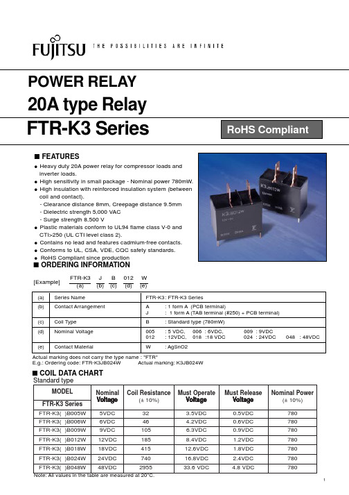
1,000m/s2 (6±1ms)
Weight
Approximately 25g
2
元器件交易网
s DIMENSIONS
q Dimensions TAB terminal type
terminal
FTR-K3 SERIES
PCB mounting type
qSchematics TAB terminal type
Dielectric between open contacts Insulation Strength between open coil-contact
1,000 VAC (50/60 Hz), 1 min. 5,000 VAC, (50/60 Hz),1 min.
Surge Strength
1.2 x 50µ s Standard wave form
4
Inrush 100VAC 200A (crest value); steady 20A; 3 x 10⁴ operations minimum
Other
Vibration Misoperation (ref. value detection 1ms) 10 to 55 Hz double amplitude of 1.5mm
32
FTR-K3( )B006W 6VDC
46
3.5VDC
0.5VDC
780
4.2VDC
0.6VDC
780
FTR-K3( )B009W 9VDC
105
6.3VDC
0.9VDC
780
FTR-K3( )B012W 12VDC
185
8.4VDCБайду номын сангаас
富士通继电器资料--MY
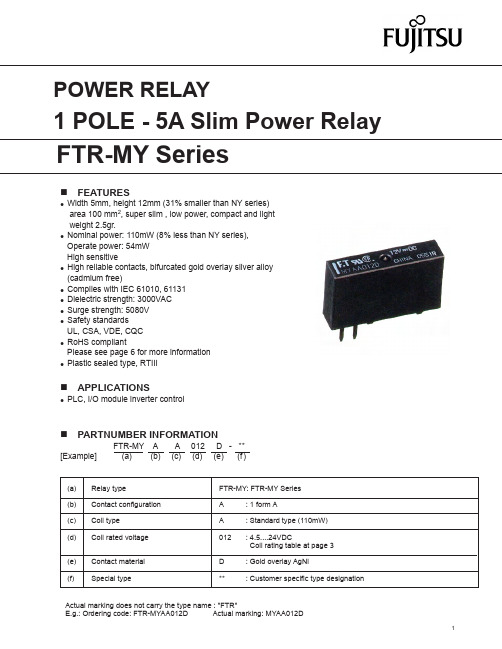
FTR-K1 SERIESn FEATURESlWidth 5mm, height 12mm (31% smaller than NY series) area 100 mm 2, super slim , low power, compact and light weight 2.5gr.l Nominal power: 110mW (8% less than NY series), Operate power: 54mW High sensitive l High reliable contacts, bifurcated gold overlay silver alloy (cadmium free)l Complies with IEC 61010, 61131l Dielectric strength: 3000VAC l Surge strength: 5080V l Safety standards UL, CSA, VDE, CQC l RoHS compliantPlease see page 6 for more information l Plastic sealed type, RTIIIn APPLICATIONSlPLC, I/O module inverter controlActual marking does not carry the type name : "FTR"E.g.: Ordering code: FTR-MYAA012D Actual marking: MYAA012D(a) Relay typeFTR-MY: FTR-MY Series (b) Contact configuration A : 1 form A(c) Coil type A : Standard type (110mW)(d) Coil rated voltage 012 : 4.5....24VDCCoil rating table at page 3 (e) Contact material D : Gold overlay AgNi(f)Special type**: Customer specific type designationn PARTNUMBER INFORMATIONFTR-MY A A 012 D - ** [Example] (a) (b) (c) (d) (e) (f)n SPECIFICATION* Minimum switching loads mentioned above are reference values. Please perform the confirmation test with actual load before production since reference values may vary according to switching frequencies, environmental contionsand expected reliability levels.n COIL RATINGCoilCode Rated CoilVoltage(VDC)Coil Resistance+/- 10% (Ohm)Must Operate Voltage (VDC) *Must Release-Voltage (VDC) *Rated Power(mW)4.5 4.5185 3.150.2251100055230 3.50.250066330 4.20.30099740 6.30.45012121,3108.40.6018182,95012.60.9024245,24016.81.2Type Compliance Contact ratingULUL 508, UL 1604E63614, E225300Flammability: UL 94-V0 (plastics)5A, 277 VAC (resistive)5A, 30 VDC (resistive)1/10 HP , 277VAC /125VAC Pilot duty: D300, C300, R300CSA C22.2 No. 14LR 40304VDE0435 part 201400147815A, 250VAC, cos φ1, 50K 5A, 30VDC, 0msec, 50Kn SAFETY STANDARDSNote: All values in the table are valid for 20°C and zero contact current.* Specified operate values are valid for pulse wave voltage.n CHARACTERISTIC DATAn REFERENCE DATAn DIMENSIONSl DimensionslWiring Diagram(BOTTOM VIEW)(BOTTOM VIEW)Unit: mm1. General InformationlAll signal and power relays produced by Fujitsu Components are compliant with RoHS directive 2002/95ECincluding amendments.l Cadmium as used in electrical contacts is exempted from the RoHS directives on October 21st, 2005. (Amendment to Directive 2002/95/EC)l All of our signal and power relays are lead-free. Please refer to Lead-Free Status Info for older date codes at: /us/downloads/MICRO/fcai/relays/lead-free-letter.pdfl Lead free solder plating on relay terminals is Sn-3.0Ag-0.5Cu, unless otherwise specified. This material has been verified to be compatible with PbSn assembly process.2. Recommended Lead Free Solder ProfilelRecommended solder Sn-3.0Ag-0.5Cu.RoHS Compliance and Lead Free Information3. Moisture SensitivitylMoisture Sensitivity Level standard is not applicable to electromechanical relays, unless otherwise indicated.4. Tin WhiskerslDipped SnAgCu solder is known as presenting a low risk to tin whisker development. No considerable length whisker was found by our in house test.We highly recommend that you confirm your actual solder conditionsFlow Solder condition:Pre-heating: maximum 120˚CSoldering: dip within 5 sec. at260˚C solder bathSolder by Soldering Iron:Soldering IronTemperature: maximum 360˚C Duration: maximum 3 sec.JapanFujitsu Component LimitedGotanda-Chuo Building3-5, Higashigotanda 2-chome, Shinagawa-ku Tokyo 141, JapanTel: (81-3) 5449-7010Fax: (81-3) 5449-2626Email: promothq@Web: North and South AmericaFujitsu Components America, Inc.250 E. Caribbean DriveSunnyvale, CA 94089 U.S.A.Tel: (1-408) 745-4900Fax: (1-408) 745-4970Email: components@Web: /components EuropeFujitsu Components Europe B.V.Diamantlaan 252132 WV HoofddorpNetherlandsTel: (31-23) 5560910Fax: (31-23) 5560950Email: info@Web: /components/Asia PacificFujitsu Components Asia Ltd.102E Pasir Panjang Road#01-01 Citilink Warehouse ComplexSingapore 118529Tel: (65) 6375-8560Fax: (65) 6273-3021Email: fcal@Web: /sg/services/micro/components/Fujitsu Components International Headquarter Offices©2010 Fujitsu Components Europe B.V. All rights reserved. All trademarks or registered trademarks are the property of their respective owners.The contents, data and information in this datasheet are provided by Fujitsu Component Ltd. as a service only to its user and only for gen-eral information purposes.The use of the contents, data and information provided in this datasheet is at the users’ own risk.Fujitsu has assembled this datasheet with care and will endeavor to keep the contents, data and information correct, accurate, comprehen-sive, complete and up to date.Fujitsu Components Europe B.V. and affiliated companies do however not accept any responsibility or liability on their behalf, nor on behalf of its employees, for any loss or damage, direct, indirect or consequential, with respect to this datasheet, its contents, data, and information and related graphics and the correctness, reliability, accuracy, comprehensiveness, usefulness, availability and completeness thereof.Nor do Fujitsu Components Europe B.V. and affiliated companies accept on their behalf, nor on behalf of its employees, any responsibility or liability for any representation or warrant of any kind, express or implied, including warranties of any kind for merchantability or fitness for particular use, with respect to these datasheets, its contents, data, information and related graphics and the correctness, reliability, accuracy, comprehensiveness, usefulness, availability and completeness thereof. Rev. August 04, 2010。
货梯配置表(销售版本120426)
富士通
选配
10
轿厢操作箱、外呼箱
不锈钢面板、楼层显示
富士通
标配
11
平层感应器
YG-1A
宁波电子一厂
标配
12
极限开关
1370
广东力东
标配
13
超载装置
富士通
标配
14
轿厢通风系统
KYDI-30
苏州恒达
标配
15
缓冲器
JHQ系列
沈阳东阳
标配
16
限速器
XCZ05
佛山永通力
标配
17
安全钳
QSX105
TVVB60芯(单开门5层及以下,贯通门2-3层)
TVVB72芯(单开门6层以上,贯通门4层以上)
河阳昊通/贝思特
标配
20
轿厢板
钢板喷塑
富士通
标配
21
轿门板
钢板喷塑
富士通
标配
22
井道防护
机械锁, 护板
富士通
选配
23
主承重梁
国标槽钢
富士通
标配
24
轿架
Q235A钢板折弯
富士通
标配
25
轿门及层门地坎
Q235A钢板折弯
20
随行电缆
TVVB60芯(单开门5层及以下,贯通门2-3层)
TVVB72芯(单开门6层以上,贯通门4层以上)
河阳昊通/贝思特
标配
21
轿厢板
钢板喷塑
富士通
标配
22
轿门板、层门板
钢板喷塑
富士通
标配
23
井道防护
机械锁, 护板
富士通
富士通继电器与继电保护

FTR(富士通) F1CA024V-NV F1AA024V-NV F1CA024V-NV F1AA024V-NV F1CA024V-NV 常F用15AVA继0电2器4V-NV
NAIS(松下) ST1-DC24V ST2-DC24V DK1A1B-DC24V DK2A-DC24V DSP1-DC24V DSP2A-DC24V
选择富士通继电器的理由
➢ 富士通电力继电器齐全 ➢ 富士通有专业的电力继电器的专业人士 ➢ 富士通的继电器参数领先 ➢ 富士通有合理的价格 ➢ 富士通的制作工厂在常州可以对国内客户需
求进行改善并保证良好的售后服务 ➢ 富士通(高见泽)继电器在电力行业有很好
的口碑
富士通电力继电器齐全 (一)
常用24V继电器
定
复位电 压
1富120士,%/通2m4Fi,n1A48A—(NAVD)1松102下%,24/Dm,S4in8PV2系A&列ST2 系列
抗 耐久 1000m/s²以上 冲 误动作 100m/s²以上 击 性
980m/s²以上 196m/s²以上
富士通的继电器参数领先(四)
❖ 高内压
富士通F1AA 松下 (AD)12,24, DSP2A&ST2 48—NV系列 12,24,48V系列
现富士通亚太地区继电器主管佐倧针对中国市场研究并开发了 1.5V,磁保持继电器和电力特殊F1继电器。
常州东明电子有限公司(日本富士通一级 代理)
成立于1994年 日本富士通高见泽在中国授权指定代理商
公司专门营销日本富士通继电器有20年 2004年与南京南瑞开始合作 2005年与武汉国测和天津双源开始合作 2006年与北京四方立德开始合作 2008年与南京钛能,上海申瑞和南京磐能科技开始合作 2010年与鲁能智能和南京电研开始合作 2011年与山东积成电子合作,鲁能智能年用量破30万只,磐能科 技年用量破40万只 2013年磐能累积用量破150万只,未有任何不良反馈。 现上海思源电气,天津紫光,南京国电南自和南京因泰莱等电力单 位都在试用当中
FTR-K1AK012W-MA中文资料

Actual marking does not carry the type name : "FTR"
E.g.: Ordering code: FTR-K1CK012W
Actual marking: K1CK012W
元器件交易网
FTR-K1 SERIES
n SAFETY STANDARD AND FILE NUMBERS
Nil :16A/5.0mm/-40 to +85˚C (standard type "K" only) -MA : 12A/3.5mm/-40 to +85˚C (standard type "K" only) -LA :10A/3.5mm/-40 to +85˚C (high sensitive "L" only) -LB :10A/5.0mm/-40 to +105˚C (high sensitive type "L" only)
10A 250VAC
14A
10A
3,000VA / 288W
2,500VAC
440VAC / 300VDC
440 VAC
10mA 5VDC
12A
10A
Minimum Inrush Current
---
---
---
Operating Temperature
-40° C to +85° C (no frost)
Resistance (at 500VDC)
Minimum 1,000 Mohms
Dielectric Strength
Between open contacts
富士通单片机中文手册

富士通电子设备用户手册F2MC-16LX Starter kit用户手册2注意事项・本资料有关内容如有变更恕不另行通知。
・本资料内所记载的设备运行情况及电路实例均是以半导体设备的标准规格及正确的使用方法为前提的,我们并不保证实际使用时所有机械的正常运作。
因此,在使用此设备时,顾客将完全承担相应的使用责任。
如有因使用此设备而造成的损害,本公司将不承担任何责任。
・本资料内所记载的设备运行情况以及电路图内所含有的技术资料并不代表可以任意使用本公司以及第三责任方的专利权以及著作权。
禁止通过本资料对第三责任方的知识产权以及相关的权利进行侵犯。
本公司对于此类相关行为以及所产生的后果将不负任何责任。
・本资料内若含有属于《外国汇率以及外国贸易法》范畴内的商品,或者含有相关范畴内的技术,则在出口本商品时必须得到相关法律的认可。
Copyright© 2005 FUJITSU LIMITED ALL right reserved © Fujitsu3目录前言 (6)1Starter-kit的安装方法 (7)1.1PC机上的软件安装 (13)1.1.1USB驱动的安装 (14)1.1.2综合开发环境SOFTUNE(限定版)的安装 (15)1.1.3ACCEMIC MDE demo version(trial版)的安装 (20)1.1.4评测板的设定以及与PC机的连接 (24)1.1.5SOFTUNE的设定与启动 (27)1.1.6ACCEMIC MDE的设定与启动 (30)1.1.7ACCEMIC MDE退出 (44)1.1.8SOFTUNE的退出 (44)1.1.9关闭Accemic的情况下启动单片机 (45)2编写使LED闪烁的程序 (46)2.1关于LED的介绍 (46)2.2LED为何会发光 (47)2.3利用单片机使LED发光的方法 (48)2.4LED发光程序的制作及运行 (51)2.4.1程序概要 (51)2.4.2程序的制作与运行 (52)2.5LED闪烁程序的制作与运行 (54)2.5.1程序概要 (54)2.5.2程序的制作与运行 (55)3用开关SW控制LED的亮灭 (57)3.1单片机如何检测SW的状态 (57)3.2通过SW控制LED程序的制作与运行 (58)3.2.1程序概要 (59)3.2.2程序的制作与运行 (59)4如何使用蜂鸣器 (61)4.1蜂鸣器内所用的材料 (61)4.1.1压电性的特点 (61)4.1.2压电材料的应用 (62)4.2单片机与压电蜂鸣器 (62)-- © Fujitsu44.2.1自励式与他励式 (63)4.2.2由单片机发出的脉冲波 (63)4.3如何使用PPG使蜂鸣器发出声音 (63)4.3.1L幅宽与H幅宽的设定 (64)4.3.2PPG count clock (64)4.4蜂鸣器程序的制作与运行 (65)4.4.1程序概要 (65)4.4.2程序的制作与运行 (67)4.4.3改变蜂鸣器的音色 (68)5利用中断来控制LED (69)5.1“中断”的概念 (69)5.2利用“中断”来检测SW的状态的方法 (70)5.3通过SW控制LED的程序(中断法) (71)5.3.1程序概要 (71)5.3.2程序的制作与执行 (72)6利用timer(定时器)来使LED闪烁 (75)6.1什么叫timer(定时器) (75)6.2通过Timer中断控制LED闪烁的程序 (76)6.2.1程序概要 (76)6.2.2程序的制作与运行 (78)7如何使用A/D(模/数)转换器 (81)7.1模拟信号与数字信号 (81)7.1.1A/D转换器的概要 (82)7.1.2滑动变阻器 (83)7.2制作一个表示电压数值的程序 (83)7.2.1程序概要 (83)7.2.2程序的制作与执行 (87)8如何使用温度传感器 (89)8.1关于温度传感器 (89)8.2温度传感器的使用方法 (90)8.3制作一个表示温度的程序 (91)8.3.1程序概要 (91)8.3.2程序的制作与执行 (94)A附录A(程序制作流程) (96)B附录B(寄存器的写入/读出方法) (104)C附录C(头文件包含路径的设定方法) (105)© Fujitsu5前言首先,非常感谢您购买本公司的Starter-kit产品。
直流高压继电器
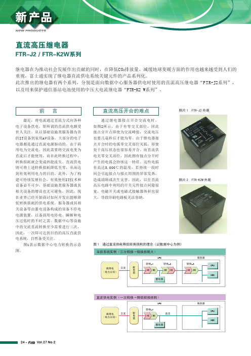
24Vol.27 No.2NEW PRODUCTS最近,将电流通过直流方式向各种电子设备供电,即所谓的直流供电颇受世人关注。
从以基础设施类服务器为首的IT设备到家用AV设备,大部分的电子电器都是通过直流电源驱动的。
由于商用电为交流电,因此需要将交流电变为直流后才能使用,而在此转换过程中,转换损耗就会变成热能流失。
直流供电则可将上述转换损耗降低至零,从而达到有效利用电力的目的。
此外,为了构建可持续发展社会,有效使用IT技术和设备必不可少,基础设施类服务器或其相关设备的增设也无可避免,因此,现在业界已经开始商讨如何开发出能够降低转换损耗的供电系统。
服务器或其相关设备等由蓄电设备构成的常备不停电电源装置,以备商用电停电、瞬断和电压过低时的不时之需。
数据中心等设施中的交流直流转换至少需要进行三次,因此,一次即可达到目的的高压直流供电系统,自然备受关注。
图1表示数据中心电力转换的示意图。
通过继电器接点开合交流电时,如图2所示,由于有零交叉部位,因此接点分开点即使为交流峰值,交流电压也要几毫秒后才能为零。
由于继电器接点开合时的电弧零交叉部位灭弧,即使处于高压状态也很容易开合。
而直流供电无零交叉部位,因此拥有接点分开时产生的电弧会持续这一特质。
这些电弧有高达3,000℃的温度,若持续一段时间会引起接点与接点周围的异常发热,造成故障或次生灾害。
因此,以往直流高压电路中利用的开关元件接点间隙很宽,电磁开关或电磁式接触器体积也很大,导致印刷电路板无法容纳。
直流高压继电器FTR-J2 / FTR-K2W系列继电器在为推动社会发展作出贡献的同时,在降低CO 2排放量、减缓地球变暖方面的作用也越来越受到人们的重视,富士通实现了继电器直流供电系统关键元件的产品系列化。
此次推出的继电器有两个系列,分别是面向数据中心服务器供电时使用的直流高压继电器“FTR-J2系列”,以及用来保护通信基站电池使用的中压大电流继电器“FTR-K2 W系列”。
富士通电子部件-接线器自动挡版(12V汽车电池,25A)系列名称FTR-G1 FTR-P3 FTR-

Fujitsu Components RELAYSAutomotive, Power, Signal, Solid StateContentProduct Line-UpAutomotive Relays Page4EV/PHV Relays Page10Power Relays Page13Signal Relays Page26Solid State Relays Page28Reference Page29About Page30Contact Page31Relays with this logo are available as “Glow Wire” versions. (-GW)These relays are IEC60335-1 compliant.Please refer to your supplier for more information or contact your local Fujitsu Office.For contact information, see the last page of this document, or https:///en/Page 3Page 4Series Name FTR-G1FTR-P3FTR-P5Description25A Compact Relay 25A Compact Relay 25A Low Noise Compact Relay Features■0.25mm contact gap■Average acoustic noise level 60dB @ 5cm ■No polarity on coil terminals ■0.25 & 0.6mm contact gap types ■THR type available ■High temp. types available(+125 o C) (THR)■Pin compatible w/ FTR-P5■No polarity on coil terminals ■Pin compatible wit FTR-P3 ■Average acoustic noise level 50dB @ 5cm ■No polarity on coil terminals Dimensions (W x L x H mm)6.6 x 13.7 x 13.57.2x17.4x13.5, (THR:7.2x17.4x14.1)9.7 x 20.4 x 16.7Weight (approx.)3.5 g 5.0 g 7.0 g Contact form1 c 1 c, (THR: 1a, 1c) 1 c Contact rating25A, 14VDC locked motor load 25A, 14VDC, locked motor load 25A, 14VDC, locked motor load Maximum carrying current25A 1 Hr 25A 1 Hr 25A 1 Hr Expected life onload example 14VDC, 25A Locked motor load100 x 103 ops. 14VDC, 25A, locked motor load 100 x 103 ops.14VDC, 25A, locked motor load 100 x 103 ops.Operating temperature-40 to +85 o C -40 to +85 o C / +125 o C (THR)-40 to +85 o C Coil voltage (DC)9 to 12 V 9 to 12 V 9 to 12 V Nominal coil power0.640 W 0.6 W / 0.8 W 0.45 to 0.455 W Dielectric strength (1 min.)Open contacts: 500VAC Coil and contacts: 500VAC Open contacts: 500VAC Coil and contacts: 500VAC Open contacts: 500VAC Coil and contacts: 500VAC Mounting / enclosureThrough hole / plastic seal Through hole / plastic seal Through hole / plastic sealTerminal layout(bottom view)1a does not carry #3 contactPage 5Series Name FTR-P4FTR-P2FTR-P7Description25A H-bridge Relay 25A Low Noise H-bridge Relay 25A Low Noise Compact Automotive Relay Features■0.25 contact gap types■Pin compatible with FTR-P2 ■No polarity on coil terminals■Pin compatible with FTR-P4 ■Average acoustic noise level 50dB @ 5cm ■No polarity on coil terminals ■0.3 mm contact gap ■Average acoustic noise level 45db @ 5cm ■No polarity on coil terminalsDimensions (W x L x H mm)14.2 x 17.4 x 13.516.5 x 21.0 x 18.017.0 x 20.8 x 14.0Weight (approx.)10.0 g 13.0 g 7.0 g Contact form1 cx2 (H-bridge)1c x 2 (H-bridge) 1 c Contact rating25A, 14VDC, locked motor load 25A, 14VDC, locked motor load 25A, 14VDC locked motor load Maximum carrying current25A 1 Hr 25A 1 Hr 25A 1 Hr Expected life on load example 14VDC, 25A, locked motor load100 x 103 ops.14VDC, 25A, locked motor load 100 x 103 ops.14VDC, 25A, locked motor load 100 x 103 ops.Operating temperature-40 to +85o C -40 to +85o C -40 to +85 o C Coil voltage (DC)9 to 12 V 9 to 12 V 12 V Nominal coil power0.6 W 0.45 to 0.455W 0.554 W Dielectric strength (1 min.)Open contacts: 500VAC Coil and contacts: 500VAC Open contacts: 500VAC Coil and contacts: 500VAC Open contacts: 500VAC Coil and contacts: 500VAC Mounting / enclosureThrough hole / plastic seal Through hole / plastic seal Through hole / plastic sealTerminal layout(bottom view)Page 6Series Name FBR51L FBR53FTR-G3 Description25A Dual coil Latching CompactAutomotive Relay30A Compact Automotive Relay30A Compact RelayFeatures■Dual coil latching■THR type available■Polarized coil terminals■THR type (-RW) available■60A inrush■No polarity on coil terminals■30A fuse capacity■THR type available■No polarity on coil terminalsDimensions (W x L x H mm)12.1 x 15.5 x 13.712.3 x 15.7 x 14.0 6.6 x 13.7 x 14.0Weight (approx.) 6.0 g 6.0 g 4.0 gContact form 1 c 1 form U 1 a, 1 cContact rating25A, 14VDC, locked motor load25A, 14VDC, resistive load30A, 14VDCMaximum carrying current30A 1Hr30A40.5A 30 minutesExpected life onload example14VDC, 25A, locked motor load200 x 103 ops. (-W1 type)50 x 103 ops. (E type)14VDC, 25A, resistive load100 x 103 ops.100 x 103 ops.Operating temperature-40 to +125 o C -40 to +125 o C -40 to +125 o CCoil voltage (DC)10 V9 to 12 V12 VNominal coil power 1.11 W0.556 to 0.6 W0.64 WDielectric strength (1 min.)Open contacts: 500VACCoil and contacts: 500VACOpen contacts: 500VACCoil and contacts: 500VACOpen contacts: 500VACCoil and contacts: 500VAC Mounting / enclosure Through hole / plastic seal Through hole / plastic seal Through hole / plastic seal Terminal layout(bottom view)1235641c contact formPage 7Series Name FBR53-HW FBR59-HW FTR-E1-HCDescription40A Compact Relay 45A/70A High Power Relay 60A compact relay Remarks■THR type (-RW) available■High power type■80A inrush ■No polarity on coil terminals■THR type (-RW) available ■High power type ■220A max. inrush ■No polarity on coil terminals ■No polarity on coil terminalsDimensions (W x L x H mm)12.3 x 15.7 x 14.015.0 x 20.0 x 16.828.3 x 43.6 x 26.8Weight (approx.)6.0 g 13.0 g 80.0 g Contact form1 form U 1 form U 1a (1 form X)Contact rating40A, 14VDC, resistive load 45A, 14VDC motor lock, 70A 14VDC resistive 60A 400VDC (at 60o C)Maximum carrying current40A 70A 1Hr 60A at 60o C Expected life on loadexample 14VDC, 40A, resistive load 100 x 103 ops.70A 14VDC, resistive 50 x 103 ops.500 x 103 ops.Operating temperature-40 to +125 o C -40 to +125 o C -40 to +60o C (at 60A)Coil voltage (DC)9 to 12 V 9 to 12V 12, 24V Nominal coil power0.855 to 0.862 W 0.45 to 0.477 W 1.2 W Dielectric strength (1 min.)Open contacts: 500VAC Coil and contacts: 500VAC Open contacts: 500VAC Coil and contacts: 500VAC Open contacts: 2,500VAC Coil and contacts: 5,000VAC MountingThrough hole / plastic seal Through hole / plastic seal Through hole / plastic sealTerminal layout(bottom view)124875 1 (+)2 (-)34Page 8Automotive relays (12V car battery)Series Name FTR-V1FTR-P3 (-06)FBR57 Description210A High Capacity LatchingRelay6A Compact Relay 12A High Power Relay Features■210A (@85°C)/120A(@125°C) continuouscurrent■Polarized coil terminals■For 24V battery applications■THR type available■No polarity on coil terminals■For 24V battery applications■70A inrush■No polarity on coil terminalsDimensions (W x L x H mm)52.8 x 84.5 x 24.77.2 x 17.5 x 14.114.4 x 20.0 x 16.2Weight (approx.)120 g 5.0 g9.4 gContact form1b 1 c 1 cContact rating Inrush 230A, 14VDCBreak 1A, 14VDC, dedicatedload6A, 28VDC12A, 28VDC, locked motor loadMaximum carrying current210A at 85o C20A 1 Hr40A 10 min. / 30A 1 Hr Expected life onload exampleInrush 230A, 14VDCBreak 1A, 14VDC120 x 103 ops.20VDC 6A resistive100 x 103 ops.28VDC, 12A, locked motor load100x103 ops.28VDC, inrush 16A/break 2.5A,free motor load500 x 103 ops.Operating temperature-40 to +125 o C-40 to +125 o C -40 to +85o CCoil voltage (DC)12V24V24 VNominal coil power28.8 W0.9W 1.5 WDielectric strength (1 min.)Open contacts: 500VACCoil and contacts: 500VACOpen contacts: 500VACCoil and contacts: 500VACOpen contacts: 500VACCoil and contacts: 500VAC Mounting / enclosure Plastic seal Through hole / plastic seal Through hole / plastic seal Terminal layout(bottom view)12345+ 4(+) 526 -3 (-)1Automotive (24V battery applications)Page 9Series Name FBR572 / 582 FBR59-HWDescription12/14A High Power Twin Relay 30A High Power Relay Features■For 24V battery applications■0.8/1.4mm contact gap■60A inrush ■No polarity on coil terminals■For 24V battery applications ■THR type available ■No polarity on coil terminalsDimensions (W x L x H mm)20.0 x 26.0 x 16.2 (FBR572)20.0 x 26.0 x 17.0 (FBR582)15.0 x 20.0 x 16.8 Weight (approx.)18.0 g 13.0 g Contact form1 c x2 1 form U Contact rating12A, 28VDC, locked motor load 30A 28VDC Maximum carrying current40A 2min.70A 1 Hr (@20o C)Expected life on load example 28VDC, 12A, locked motor load100 x 103 ops. (FBR572, 582)28VDC, inrush 15A/break 2.5A,free motor load500 x 103 ops. (FBR572)28VDC 20A resistive 100 x 103 ops. Operating temperature -40 to +85 o C-40 to +125 o C Coil voltage (DC)24 V12, 24 V Nominal coil power 1.5W / 3.4W1.2 W Dielectric strength (1 min.)Open contacts: 500VACCoil and contacts: 500VACOpen contacts: 500VAC Coil and contacts: 500VAC Mounting / enclosure Through hole / plastic seal Through hole / plastic sealTerminal layout(bottom view)Automotive relays (24V battery applications)124578Page 10EV/PHV relays (DC control)Series Name FTR-B3FTR-B4FTR-J2Description2A Low Profile Relay 2A Slim Type Relay 10A 450VDC Small High Voltage DC Relay Features■Space saving versions available■THT and SMT versions ■Polarity on coil terminals ■Space saving versions available ■THT and SMT versions ■Polarity on coil terminals ■Special arc extinguishing provision ■150A inrush per contact ■Polarity on coil terminalsDimensions (W x L x H mm)7.2 x 10.6 x 5.25 (SMT) 5.7 x 10.6 x 9.7 (SMT)23.5 x 24.0 x 27.0Weight (approx.)0.85g 1.0g 26.0g Contact form2c 2c 1a x 2Contact rating 0.3A 125VAC/1A 30VDC 0.3A 125VAC/1A 30VDC 10A 200VDC (NO contact usedindependently)10A 450VDC (2 contactsconnected in series)Maximum carrying current 2A 2A 12AMin. switching load (ref.)10mVDC 0.01mA 10mVDC 0.01mA 5VDC 100mAExpected life on loadexample100 x 103 ops.100 x 103 ops.10 x 103 ops.Coil voltage (DC)1.5 to 24V 1.5 to 24V 5 to 110V Nominal coil power0.14 to 0.23W 0.14 to 0.23W 1.06W (2 contacts connected in series)Surge strength2,500V 2,500V 10,000V Dielectric strength (1 min.)Open contacts: 1,000VAC Coil and contacts: 1,500VAC Open contacts: 1,000VAC Coil and contacts: 1,500VAC Open contacts: 1,000VAC Coil and contacts: 4,000VAC Safety standardsUL, CSA, BSI, FCC68, Telcordia, IEC60950-1UL, CSA, BSI, FCC68, Telcordia, IEC60950-1UL, VDE Mounting / EnclosureThrough hole or surface mount / plastic seal Through hole or surface mount / plastic seal Through hole/ flux proof Terminal layout(bottom view) (Bottom view)(Top view)(Bottom view)(Top view)Series Name FTR-E1Description 20A/30A, 450VDC High Voltage DC RelayFeatures■cULus recognized typesavailable■Polarized on coil terminals■No polarity on contactsDimensions (W x L x H mm)28.3 x 43.6 x 36.8Weight (approx.)75.0 gContact form1a (1 Form X)Contact rating20A 450VDC (20A type)30A 450VDC (30A type)Maximum carrying current40A (@ +85 o C)Min. switching load (ref.)6VDC, 1AExpected life on load example10 x 103 ops. (20A 450VDC)*5 x 10³ ops (30A 450VDC) ** with varistorCoil voltage (DC)12, 24VNominal coil power0.9WSurge strength-Dielectric strength (1 min.)Open contacts: 2,500VACCoil and contacts: 5,000VAC Safety standards-Mounting / Enclosure Through hole / plastic seal Terminal layout(bottom view)Series NameFTR-K1(-HT / -KW)FTR-K3 (-WG / -WS / -PV / -PS)FTR-K5Description 16A Plastic sealed 105o C type 25/32A Wide Contact Gap Relay 40A relay for on-board charger Features■UL TV-5 available ■5mm pitch■Creepage/clearance>10mm■No polarity on coil terminals■Conform to VDE0127■ 1.5mm or 1.8mm contact gap■No polarity on coil terminals■For 6.6kW standard charger ■Operable at up to 105o C■No polarity on coil terminalsDimensions (W x L x H mm)12.7 x 29.0 x 15.715.7 x 30.1 x 23.318.0 x 30.5 x 29.7Weight (approx.)13.0g 25.0 to 26.0g 39.0g Contact form 1a, 1c1a1aContact rating16A 250VAC/24VDC 25A/32A 250VAC 32A 250VACMaximum carrying current 20A25A, 32A 40A (at 105o C, 8mm 2 cable)Min. switching load (ref.)5VDC 100mA5VDC 100mA 6VDC 1AExpected life on load example10 x 103 ops. to 100 x 103 ops.100 x 103 ops. (25A)* 30 x 103 ops. (32A)** 1.5mm gap type1,000 ops. (plastic seal)30 x 103 ops. (flux proof)Coil voltage (DC) 5 to 110V 5 to 48V 5 to 24V Nominal coil power 0.4 to 0.43mW 0.78 to 1.4W0.9W Surge strength10,000V8,500VAC(25A), 6,000V (32A)-Dielectric strength (1 min.)Open contacts: 1,000VAC Coil and contacts: 5,000VAC Open contact 2,500VAC Coil and contacts: 5,000V (25A), 4,000V (32A)Open contacts: 1,000VAC Coil and contacts: 5,000VAC Safety standards UL, CSA, VDEUL, VDE, CQC-Mounting / Enclosure Through hole / plastic seal or flux proofThrough hole / plastic sealThrough hole /plastic seal or flux proofTerminal layout (bottom view)Orientation markOrientation markFTR-K1-AK FTR-K1-CK COMNO56784321NC COM NO 567843211234Power relays (3A ~ 5A)Series NameNYJYFTR-F3 (3A)Description 5A Slim Type Relay 3/5A Compact Relay 3A Slim Type RelayRemarks■Socket available (-NYP) ■Compliant to IEC61010-2-201 and 61131 reinforced insulation■Compatible with SN solid state relay■No polarity on coil terminals■Socket available (-P) ■Pin compatible with SJ solid state relay■No polarity on coil terminals■IEC60695-2-11 types (-GW) ■AgNi contacts■No polarity on coil terminalsDimensions (Wx L x H mm) 5.0 x 20.1 x 17.59.8 x 20.0 x 12.87.0 x 20.3 x 15.0Weight (approx.) 3.5 g 5.0 g 4.0 g Contact form 1 a1 a1 aContact rating (resistive load)5A, 250VAC/30VDC 3A, 250VAC/30VDC (3A type)5A, 250VAC/30VDC (5A type)3A, 125VAC/30VDC Maximum carrying current 5A5A5AMinimum switching load (ref.)5VDC, 1mA100m VDC 0.01mA (W)5VDC 10mA (G, HG)5VDC 100mA (R, HR)5VDC 10mAElectrical life (rated load)100 x 103 ops. (at 3A, 250VAC, 30VDC)50 x 103 ops. (at 5A, 250VAC,30VDC)100 x 103 ops.200 x 103 ops.Coil voltage (DC) 4.5 to 24 V 4.5 to 48 V 5 to 24 V Nominal coil power 0.12 W 0.2 to 0.36 W 0.2W Surge strength5,080 V4,000 V10,000 VDielectric strength (1 min.)Open contacts: 750VACCoil and contacts: 3,000VAC Open contacts: 750VACCoil and contacts: 2,000VAC Open contacts: 750VAC Coil and contacts: 4,000VAC Safety standards UL, CSAUL, CSAUL, CSA, VDE, CQCMounting / Enclosure Through hole / plastic sealThrough hole / plastic sealThrough hole / plastic seal or flux proofTerminal layout (bottom view)Series NameFTR-F3 (5A)FTR-F3 (5A TV rating)FTR-F3 (10A)Description 5A Slim Type Relay 5A Slim or Flat Type Relay 10A Slim Type Relay Remarks■IEC60335-1 types (-GW) ■AgNi contacts■No polarity on coil terminals■Right angle versions avail-able■TV-3 or TV-5 rating ■AgSnO2 contacts■No polarity on coil terminals■AgNi contacts■No polarity on coil terminalsDimensions (Wx L x H mm)7.0 x 20.3 x 15.07.0 x 20.3 x 15.0 (slim) 15.0 x 20.3 x 7.0 (flat)7.0 x 20.3 x 15.0 Weight (approx.) 4.0 g 6.0 g 4.0 g Contact form 1a1 a1 aContact rating (resistive load)5A, 250VAC/30VDC 5A, 250VAC/30VDC 10A, 250VAC Maximum carrying current 5A5A10AMinimum switching load (ref.)5VDC 10mA 5VDC 10mA 5VDC 100mAElectrical life (rated load)100 x103 ops.50 x 103 ops.50 x 103 ops. (flux proof type)10 x 103 ops (plastic sealed type)Coil voltage (DC) 5 to 24 V 3 to 24 V 5 to 24 V Nominal coil power 0.2W 0.28W 0.2 W Surge strength10,000 V10,000 V10,000 VDielectric strength (1 min.)Open contacts: 750VAC Coil and contacts: 4,000VAC Open contacts: 750VAC Coil and contacts: 4,000VAC Open contacts: 750VAC Coil and contacts: 4,000VAC Safety standards UL, CSA, VDE, CQC UL, CSA, VDEUL, CSA, VDE, CQCMounting / Enclosure Through hole / flux proofThrough hole / plastic sealThrough hole / plastic seal or flux proofTerminal layout (bottom view)1234COMNOOrientation mark(slim type)(flat type)2134NO COMSeries Name FTR-F3 (5A 1 transfer)FTR-MY FTR-F2 Description5A 1 TransferType Relay5A Slim Type Relay5A High profile RelayRemarks■ 1 form C type■AgNi contacts■No polarity on coil terminals ■Compliant to IEC61010-2-201, 61131-2 reinforcedinsulation■Conforms to ANSI/ISA12.12.01■Creepage, clearance>5.6mm■No polarity on coil terminals■TV-5 rated■High sensitive coil types■No polarity on coil terminalsDimensions (Wx L x H mm)7.0 x 23.4 x 15.0 5.0 x 20.0 x 12.011.0 x 24.0 x 25.0Weight (approx.) 6.0 g 2.5 g13.0 gContact form1c 1 a 1 aContact rating(resistive load)10A, 250VAC/30VDC5A, 250VAC/30VDC5A, 250VAC/30VDC Maximum carrying current5A5A5AMinimum switching load (ref.)5VDC 10mA 5VDC 1mA5VDC 100mAElectrical life (rated load)50 x 103 ops. 5 x 10³ ops.100 x 103 ops.Coil voltage (DC) 5 to 24 V 4.5 to 24 V 5 to 48 V (sensitive: 5 to 24 V) Nominal coil power0.36 W0.11 W0.25 to 0.53 WSurge strength10,000 V5,080 V10,000 VDielectric strength (1 min.)Open contacts: 750VACCoil and contacts: 4,000VAC Open contacts: 750VACCoil and contacts: 3,000VACOpen contacts: 1,000VACCoil and contacts: 4,000VACSafety standards UL, CSA, VDE, CQC UL, CSA, VDE, CQC UL, CSA, VDE, CQC Mounting / Enclosure Through hole / plastic seal Through hole / plastic seal Through hole / flux proofTerminal layout(bottom view)56Series NameJVFTR-F1 (5A)FTR-F1 (8A)Description 5A Medium Load Relay 2 poles, 5A Low Profile Relay 2 poles, 8A Low Profile Relay Remarks■High sensitive type available■No polarity on coil terminals■Pin compatible with VB se-ries■TV-3 rating available (2a) ■Clear cover available (-RG) ■Sensitive coil types■8A types FTR-F1R available■No polarity on coil terminals■Pin compatible with VB series■TV-3 rating available (2a) ■Clear cover available (-RG) ■Sensitive coil types available■No polarity on coil terminalsDimensions (W x L x H mm)10.0 x 17.5 x 12.512.8 x 29.0 x 16.512.8 x 29.0 x 16.5Weight (approx.) 4.3 g 12.0 g 12.0 g Contact form1 a2 a, 2 c2 a, 2 cContact rating (resistive load)5A, 250VAC/30VDC 5A, 250VAC/24VDC 8A, 250VAC/24VDC Maximum carrying current 5A7A8AMinimum switching load (ref.)5VDC, 100mA 5VDC 10mA 5VDC 10mA Electrical life (rated load)100 x 103 ops.100 x 103 ops.50 x 103 ops.Coil voltage (DC) 3 to 48 V(High sensitive: 3 to 24V) 1.5 to 110 V(High sensitive: 1.5 to 48V) 1.5 to 110 V(High sensitive: 1.5 to 48V)Nominal coil power 0.2 to 0.3 W 0.4 to 0.55 W 0.4 to 0.55 W Surge strength10,000 V10,000 V10,000 VDielectric strength (1 min.)Open contacts: 750VACoil and contacts: 5,000VAC Open contacts: 1,000VAC Coil and contacts: 5,000VAC Open contacts: 1,000VAC Coil and contacts: 5,000VAC Safety standards UL, CSA, VDE, CQC UL, CSA, VDE, CQC UL, CSA, VDEMounting / Enclosure Through hole / plastic sealThrough hole / plastic sealThrough hole / flux proofTerminal layout (bottom view)857421NONOCOMCOM87654321NO NOCOM COMNC NCOrientation markOrientation markFTR-F1A typeFTR-F1C type857421NONOCOMCOM87654321NO NOCOM COMNCNCOrientation markOrientation markFTR-F1A typeFTR-F1C typeSeries NameFTR-F1LFTR-LYJSDescription 2 poles 8A Low Profile Latching Relay 6A Slim Type Relay 8A Low Profile Relay Remarks■Latching relay ■ 1 and 2 coil types■Polarized coil terminals■Ultra slim■Socket type available■Right angle type available■Creepage/clearance >8mm■ 3.2 and 5 mm pitch types ■Creepage/clearance >8mm ■Au plated version available■No polarity on coil terminalsDimensions (W x L x H mm)12.8 x 29.0 x 16.5 5.0 x 28.0 x 15.0 (straight)10.0 x 29.0 x 12.5Weight (approx.)13.0 g 5.0 g 8.0 g Contact form2 a, 2 c1 a, 1 c1 a, 1 cContact rating (resistive load)8A, 250VAC/24VDC 6A, 250VAC/24VDC 8A, 250VAC/24VDC Maximum carrying current 8A6A10AMinimum switching load (ref.)5VDC 10mA 5VDC, 10mA (-V type) 5VDC 100mA (-Y , -E type)5VDC 100mA, 5VDC 10mA (3µAu)Electrical life (rated load)50 x 103 ops.30 x 103 ops. NC 50 x 103 ops. NO 20 x 103 ops. to 50 x 103 ops.(Depends on contact material)Coil voltage (DC) 5 to 24 V 5 to 60 V5 to 60 V Nominal coil power 0.4 to 0.6 W 0.17 W / 0.217 mW 0.22 to 0.29 W Surge strength10,000 V6,000 V10,000 VDielectric strength (1 min.)Open contacts: 1,000VAC Coil and contacts: 5,000VAC Open contacts: 1,000VAC Coil and contacts: 4,000VAC Open contacts: 1,000VAC Coil and contacts: 5,000VAC Safety standards UL, CSA, VDE, CQC UL, CSA, VDEUL, CSA, VDE, CQC Mounting / Enclosure Through hole / plastic sealThrough hole / plastic sealThrough hole / plastic sealTerminal layout (bottom view)1 N.O.5 COM.431 N.O.5 COM.43*857421NONOCOMCOM87654321NO NOCOM COMNCNCOrientation markOrientation markFTR-F1A typeFTR-F1C type**omitted on 1 form A type(straight)3(※)543 (*)21(right angle)(1 coil)Series NameJSLJS-KSFTR-H2Description 8A Low Profile Latching Relay 8A Low Profile High Inrush Relay 10A High Profile Relay Remarks■Latching type■ 1 and 2 coil types available ■ 3.2mm pitch■Creepage/clearance >8mm■Polarized coil terminals■1000W lamp load ■65A inrush ■5mm pitch■Creepage/clearance >8mm■No polarity on coil terminals■TV-5 rated■High sensitive types available■Creepage/clearance >6mm■No polarity on coil terminalsDimensions (W x L x H mm)10.0 x 29.0 x 12.510.0 x 29.0 x 12.511.0 x 24.0 x 25.0Weight (approx.)8.0 g 8.0 g 13.0 g Contact form1 a, 1 c1 a1 aContact rating (resistive load)8A, 250VAC/24VDC8A, 250VAC/24VDC10A, 250VAC/30VDCMaximum carrying current 10A10A10AMinimum switching load (ref.)5VDC 100mA 5VDC 100mA5VDC 100mAElectrical life (rated load)50 x 103 ops. 100k @ rated load25k @ lamp load (TV4)100 x 103 ops. @ rated load25 x 103 ops. (@ lamp load TV-5)Coil voltage (DC) 3 to 24 V5 to 60 VDC 5 to 48 V (High sensitive: 5 to 24V)Nominal coil power 0.22 to 0.25 (1coil), 0.48 (2 coils)0.22 to 0.29 W 0.25 to 0.53 W Surge strength10,000 V10,000 V10,000 VDielectric strength (1 min.)Open contacts: 1,000VAC Coil and contacts: 5,000VAC Open contacts: 1,000VAC Coil and contacts: 5,000VAC Open contacts: 1,000VAC Coil and contacts: 4,000VAC Safety standards UL, CSA, VDEUL, CSAUL, CSA, VDE, CQC Mounting / Enclosure Through hole / plastic sealThrough hole / plastic sealThrough hole / flux proofTerminal layout (bottom view)1 Set6 5 (-) +3 (+) -2 Reset1 Set65 (-) +3 (+) -2 Reset(a(a(a ommited on 1 a types1 N.O.5 COM.43Series Name FTR-J2Description10A, 450VDC Small HighVoltage DC RelayRemarks■Special arc extinguishing provision■150A inrush per contact■Polarized contact terminals■No polarity on coil terminalsDimensions (W x L x H mm)23.5 x 24.0 x 27.0Weight (approx.)26.0 gContact form1a x 2Contact rating (resistive load)10A, 200VDC (use NO contact independently)or 10A, 450VDC600VDC max. (2 contacts connected in series) Maximum carrying current12AMinimum switching load (ref.)5VDC, 100mAElectrical life (Rated load)10 x 103 ops.Coil voltage (DC) 5 to 110 VNominal coil power0.53W each contactSurge strength10,000 VDielectric strength (1 min.)Open contacts: 1,000VACCoil and contacts: 4,000VACSafety standards UL, VDEMounting / Enclosure Through hole / flux proofTerminal layout(bottom view)Power relays (>10A ~ 20A)Series Name FTR-K1FTR-K1-E FTR-K1-KSDescription16A Inrush 80A Type16A AgNi Contact16A Inrush 120A TypeType FTR-K1AK( )T FTR-K1CK( )W FTR-K1AK( )E FTR-K1CK( )E FTR-K1AK( )T-KSFTR-K1CK( )T-KS Remarks■Au plated types (-BG)■Creepage/clearance >10mm■UL-TV-5 (N.O.)■IEC60335-1 type (-GW)available■Transparent cover■available■No polarity on coil terminals■Contact material AgNi■Clear cover types (-RG)available■5mm pitch■Creepage/clearance>10mm■No polarity on coil terminals■5mm pitch■Creepage/clearance >10mm■UL TV-8 (N.O.)■No polarity on coil terminalsDimensions (W x L x H mm)12.7 x 29.0 x 15.712.7 x 29.0 x 15.712.7 x 29.0 x 15.7Weight (approx.)13.0 g13.0 g13.0 gContact form 1 a 1 c 1 a 1 c 1 a 1 cContact rating (resistive load)16A, 250VAC/24VDC16A, 250VAC/24VDC16A, 250VACMaximum carrying current20A20A20AMinimum switching load (ref.)5VDC 100mA5VDC 100mA5VDC 100mAElectrical life (Rated load)100 x 103 ops.(AC)100 x 103 ops.(DC)50 x 103 ops.(AC)30 x 103 ops.(DC)100 x 103 ops.(AC)100 x 103 ops.(DC)50 x 103 ops.(AC)30 x 103 ops.(DC)100 x 103 ops.(AC)25 x 103 ops.(TV-8)30 x 103 ops.(AC)25 x 103 ops.(TV-8) (N.O.) Coil voltage (DC) 5 to 110 VDC 5 to 110 V 5 to 110 VNominal coil power0.4 to 0.43W0.4 to 0.43 W0.4 to 0.43 WSurge strength10,000 V10,000 V10,000 VDielectric strength (1 min.)Open contacts: 1,000VACCoil and contacts: 5,000VACOpen contacts: 1,000VACCoil and contacts: 5,000VACOpen contacts: 1,000VACCoil and contacts: 5,000VAC Safety standards UL, CSA, VDE, CQC UL, CSA, VDE UL, CSA, VDEMounting / Enclosure Through hole / flux proof Through hole / flux proof Through hole / flux proof Terminal layout(bottom view)Orientation markOrientation markFTR-K1-AKFTR-K1-CKCOM NO56784321NC COM NO56784321Orientation markFTR-K1-AKFTR-K1-CKCOM NO56784321NC COM NO56784321Orientation markCOM NO56784321NC COM NO56784321Orientation markPage 21Series NameFTR-K1-MA / MBFTR-K1-HTFTR-K1-KWDescription 12A Type 16A High Temperature 1050C Type 16A Plastic Sealed 1050C Type Type FTR-K1AK( )W-(MA;MB)FTR-K1CK( )W-(MA;MB)FTR-K1AK( )T-HT FTR-K1CK( )W-HTFTR-K1AK( )W-KW FTR-K1CK( )W-KWRemarks■Au plated types (-BG) ■Clear cover types (-RG) ■ 3.5mm pitch MA type ■5mm pitch MB type■Creepage/clearance >10mm■No polarity on coil terminals■5mm pitch■Creepage/clearance >10mm ■UL TV-5 (1a)■EC60335-1 type (-GW)available■No polarity on coil terminals ■5mm pitch■Creepage/clearance >10mm■UL TV-5 (1a)■No polarity on coil terminalsDimensions (W x L x H mm)12.7 x 29.0 x 15.712.7 x 29.0 x 15.712.7 x 29.0 x 15.7Weight (approx.)13.0 g 13.0 g 13.0 gContact form1 a 1 c1 a 1 c1 a1 cContact rating (Resistive load)12A, 250VAC/24VDC16A, 250VAC/24VDC16A, 250VAC Maximum carrying current 14A20A20AMinimum switching load (ref.)5VDC 100mA 5VDC 100mA 5VDC 100mAElectrical life (Rated load)100 x 103 ops. (AC)100 x 103 ops. (DC)100 x103 ops (AC)100 x103 ops.(DC)25 x 103 ops. (1a / TV-5)50 x 103 ops. (AC)30 x 103 ops. (DC)20 x 103 ops. (AC)10 x 103 ops. (AC)Coil voltage (DC) 5 to 110 V 5 to 110 VDC 5 to 110 V Nominal coil power 0.4 W / 0.43 W 0.4 to 0.43W 0.4 to 0.43W Surge strength10,000 V10,000 V10,000 VDielectric strength (1 min.)Open contacts: 1,000VAC Coil and contacts: 5,000VAC Open contacts: 1,000VAC Coil and contacts: 5,000VAC Open contacts: 1,000VAC Coil and contacts: 5,000VAC Safety standards UL, CSA, VDEUL, VDEUL, VDEMounting / Enclosure Through hole / flux proofThrough hole / flux proofThrough hole / plastic sealTerminal layout(bottom view)Orientation markOrientation mark54286 (*)NCCOM NO5428NCCOM NO6 (*) (*): No 6 is omitted on 1aFTR-K1-MAFTR-K1-MBOrientation markOrientation markFTR-K1-AK FTR-K1-CK COMNO56784321NC COM NO 56784321Orientation markOrientation mark FTR-K1-AK FTR-K1-CK COMNO56784321NC COM NO 56784321。
富士通 F-01C中文说明书

富士通F-01C中文说明书-CAL-FENGHAI.-(YICAI)-Company One1F-01C中文使用说明书本文由Leica sennheiser原创翻译,版权所有!译者网站:译者Twitterxie107目录手机各部位简介------------------------------------------------第3页待机桌面图标功能简介 -----------------------------------第5页设置简介 ------------------------------------------------第6页安全设置(各种锁)-----------------------------------------第8页TIPS -----------------------------------------第9页摄影与摄像 -----------------------------------------------第11页界面简单翻译 -----------------------------------------------第13页1】耳塞孔2】亮度感应器3】主屏幕(触摸屏)4】拾音器/麦克风5】菜单键(显示菜单)6】邮件功能键(输入法切换键)7】后退键/清除键8】拨打键9】1-9主键盘10】* 星号键/公众模式选择键11】i-Widget模式/TV键12】搜索快捷键13】温度/湿度感应器14】多维导航键15】拍照快捷键16】i功能键17】开关机/挂机键18】#号键/静默模式选择键19】多任务切换键20】充电指示灯 21】小显示屏22】来电/短信指示灯 23】内藏天线24】背部麦克风 25】指纹感应器26】相机镜头 27】扬声器28】红外传输口 29】ic 标识30】照明灯 31】后盖32】座充插口垫片 33】背盖锁34】手机挂绳口 35】usb数据、充电口36】hdmi接口 37】1seg天线38】摄影快捷键、音量键开机后,选择英语界面:【键盘键位对应屏幕所示功能】文字输入界面,按切换输入语言。
TK系列热过载继电器
最大倾斜度为±30°; 安装地点的污染等级为 3 级; 在无爆炸危险的介质中,且介质中无足以腐 蚀 金属和 破 坏绝 缘 的 气体 与 导 电尘 埃 的地 方; 在没有雨雪侵袭的地方;
适用范围
SC系列交流接触器主要用于交流频率50Hz和 60Hz, 额 定 电 压 至 1000V, 额 定 电 流 至 800A的电力系统中接通和分断电路,并可与 适当的热过载继电器或电子式保护装置组合 成电动机起动器,以保护运行中可能发生过 载的设备。 产品执行下列标准: IEC60947-1:2000 GB/T14048.1-2000《 低 压
开关设备和控制设备 总则》 IEC60947-4-1:2000 GB14048.4-1993《低压开关 设备和控制设备 低压机电式接触器和电动机起动 器》 IEC60947-5-1:2000 GB14048.5-2001《 低 压 开 关设备和控制设备 控制电路电器和开关元件 第 一部分 机电式控制电路电器》
10~17
6~13
10~17
6~13
10~17 10~18
6~13 8~18
10~18
8~18
39~45
27~33
31~37
30~36
31~37
30~36
38~44
31~37
38~44
31~37
43~49
41~47
43~49
41~47
69~75
56~62
69~75
56~62
控制线圈特性(直流操作时) 表4
公司引进了日本富士电机先进的设计技术和制造技术以及 生产管理模式。公司拥有日本富士电机独立自主开发设计的世 界上最先进的高速全自动铁芯生产线,它具有冲压、叠层一次 成型等特点。公司引进了用于热过载继电器整定电流用的短时 间角度调整机、激光刻度机、全自动高速六轴线圈卷线机、日 本法纳克(FANUC)生产的全自动注塑机、会田(AIDA)生 产的高速冲床、全自动触头铆、焊接机以及一大批由日本富士 电机制造的工装模具,从而保证了产品质量的一致性。
富士通道闸参数

FJC-Z1118天翼挡闸机械化拉丝工艺,(天翼挡闸)卡等读卡器集成突发情况下,系统具有应急措施,保证通道畅通无阻,方便人员及时疏散;统一标准的对外电气接口,可与多种读卡器相挂接,并可通过管理计算机实13. 整个系统采用直流无刷电机,低功耗、运行平稳、不抖动、噪音小;14. 根据现场使用环境和人流通行速度,闸机挡板开启及关闭速度和收缩力度均可在主控器上调节;15. 在低温地区,设备可配置加温装置。
产品描述:富士智能FJC-Z1118属于天翼系列挡闸,箱体材质采用标准304不锈钢,流线形结构,箱体内设计有专业导水槽,可安装于室内、室外,适合于人流量大的公园、车站、展馆、体育馆等场合,具有计数、考勤、限流等功能,并可配合售检票系统平台,实现售票、验票、检票、回收票等管理功能。
FJC-Z1128天智挡闸机械化拉丝工艺,(天智挡闸)卡等读卡器集成突发情况下,系统具有应急措施,保证通道畅通无阻,方便人员及时疏散;统一标准的对外电气接口,可与多种读卡器相挂接,并可通过管理计算机实14. 根据现场使用环境和人流通行速度,闸机挡板开启及关闭速度和收缩力度均可在主控器上调节;15. 在低温地区,设备可配置加温装置。
产品描述:富士智能FJC-Z1118属于天翼系列挡闸,箱体材质采用标准304不锈钢,流线形结构,箱体内设计有专业导水槽,可安装于室内、室外,适合于人流量大的公园、车站、展馆、体育馆等场合,具有计数、考勤、限流等功能,并可配合售检票系统平台,实现售票、验票、检票、回收票等管理功能。
FJC-Z1138天威挡闸(天威挡闸)机械化拉丝工艺,卡等读卡器集成突发情况下,系统具有应急措施,保证通道畅通无阻,方便人员及时疏散;统一标准的对外电气接口,可与多种读卡器相挂接,并可通过管理计算机实根据现场使用环境和人流通行速度,闸机挡板开启及关闭速度和收缩力度均15. 在低温地区,设备可配置加温装置。
产品描述:富士智能FJC-Z1138属于天威系列挡闸,箱体材质采用标准304不锈钢,菱形立体外观,箱体内设计有专业导水槽,可安装于室内、室外,适合于人流量大的公园、车站、展馆、体育馆等场合,具有计数、考勤、限流等功能,并可配合售检票系统平台,实现售票、验票、检票、回收票等管理功能。
继电器的工作原理和特性详细解说
继电器的工作原理和特性继电器是一种电子控制器件,它具有控制系统(又称输入回路)和被控制系统(又称输出回路),通常应用于自动控制电路中,它实际上是用较小的电流去控制较大电流的一种“自动开关”。
故在电路中起着自动调节、安全保护、转换电路等作用。
电磁继电器的工作原理和特性电磁式继电器一般由铁芯、线圈、衔铁、触点簧片等组成的。
只要在线圈两端加上一定的电压,线圈中就会流过一定的电流,从而产生电磁效应,衔铁就会在电磁力吸引的作用下克服返回弹簧的拉力吸向铁芯,从而带动衔铁的动触点与静触点(常开触点)吸合。
当线圈断电后,电磁的吸力也随之消失,衔铁就会在弹簧的反作用力返回原来的位置,使动触点与原来的静触点(常闭触点)吸合。
这样吸合、释放,从而达到了在电路中的导通、切断的目的。
对于继电器的“常开、常闭”触点,可以这样来区分:继电器线圈未通电时处于断开状态的静触点,称为“常开触点”;处于接通状态的静触点称为“常闭触点”。
热敏干簧继电器的工作原理和特性热敏干簧继电器是一种利用热敏磁性材料检测和控制温度的新型热敏开关。
它由感温磁环、恒磁环、干簧管、导热安装片、塑料衬底及其他一些附件组成。
热敏干簧继电器不用线圈励磁,而由恒磁环产生的磁力驱动开关动作。
武汉中试高测电气有限公司恒磁环能否向干簧管提供磁力是由感温磁环的温控特性决定的。
固态继电器(SSR)的工作原理和特性固态继电器是一种两个接线端为输入端,另两个接线端为输出端的四端器件,中间采用隔离器件实现输入输出的电隔离。
固态继电器按负载电源类型可分为交流型和直流型。
按开关型式可分为常开型和常闭型。
按隔离型式可分为混合型、变压器隔离型和光电隔离型,以光电隔离型为最多。
继电器主要产品技术参数额定工作电压是指继电器正常工作时线圈所需要的电压。
根据继电器的型号不同,可以是交流电压,也可以是直流电压。
直流电阻吸合电流是指继电器能够产生吸合动作的最小电流。
在正常使用时,给定的电流必须略大于吸合电流,这样继电器才能稳定地工作。
- 1、下载文档前请自行甄别文档内容的完整性,平台不提供额外的编辑、内容补充、找答案等附加服务。
- 2、"仅部分预览"的文档,不可在线预览部分如存在完整性等问题,可反馈申请退款(可完整预览的文档不适用该条件!)。
- 3、如文档侵犯您的权益,请联系客服反馈,我们会尽快为您处理(人工客服工作时间:9:00-18:30)。
FTR-K1 SERIESn FEATURESlPeak 80A inrush current (1 form A type)l Low profile (height: 15.7mm)l HIGH INSULATIONInsulation distance (between coil and contacts): 10mm min. Dielectric strength: 5KV Surge strength: 10KV l Class F coil wire l Low coil power (400mW)l Cadmium free contacts l SAFETY STANDARDSUL, CSA, VDE, SEMKO approvedUL, CSA TV-5 rating approved (1 form A type)l Flux proof, RTII l RoHS compliantPlease see page 6 for more informationActual marking does not carry the type name : "FTR"E.g.: Ordering code: FTR-K1CK012W Actual marking: K1CK012W(a) Relay typeFTR-K1 : FTR-K1 Series (b) Contact configuration A : 1 form A (SPST-NO)C : 1 form C (SPDT) (standard type "K" only)(c) Coil type K: Standard type (400mW / Flux proof)(d) Coil rated voltage 012 : 5....110VDCCoil rating table at page 3(e) Contact material / TV type W : AgSnO 2 (1 form C contact type only)T : AgSnO 2 / TV-5 rated (1 form A / TV-5 contact type only) (f) Special type Nil : Standard type (without gold plate)BG: Gold plated 3µmn PARTNUMBER INFORMATIONFTR-K1 C K 012 W - BG [Example] (a) (b) (c) (d) (e) (f)SPECIFICATIONn* 2: Minimum switching loads mentioned above are reference values. Please perform the confirmation test with actual load before production since reference values may vary according to switching frequencies, environmental contionsn COIL RATINGNote: All values in the table are valid for 20°C and zero contact current. * Specified operate values are valid for pulse wave voltage.Type Compliance Contact ratingUL UL 508E63614FTR-K1CK ( ) W FTR-K1AK ( ) T Flammability: UL 94-V0 (plastics)16A, 277VAC/24VDC (resistive)20A, 277VAC (resistive)1 HP, 277VAC1/2 HP, 125VAC1/8 HP, 125VACTV-5, 120VAC, 25,000 cycles(only make contact)Pilot duty: B30016A, 24VAC (resistive)16A, 277VAC (resistive)20A, 277VAC (resistive)1 HP, 277VAC1/2 HP, 125VACTV-5, 120VAC 25,000 cyclesPilot duty: A300CSA C22.2 No. 14LR 40304VDE0435, 0631, 0700, 0860,4001384816A, 250VAC (cosφ=1), 85˚C3.5A, 250VAC (cosφ=0.4), 85˚C16 A 24VDC (0ms), 85˚C5A/80A, 250VAC 10,000 times, 85˚C (only make contact)SEMKO EN 61058-1:1992 and A1EN 61095:1993 and A1+A11250VAC, 16 (3)A 40T855A/80A 250VAC 40T85 (only make contact)n SAFETY STANDARDS Complies with NEMKO, DEMKO, FIMKOn CHARACTERISTIC DATAlDimensionsnDIMENSIONSUnit: mmlSchematics (BOTTOM VIEW)l PC board mountinghole layout(BOTTOM VIEW)FTR-K1AK ( ) TFTR-K1CK ( ) Wl DimensionslSchematics(BOTTOM VIEW)l PC board mountinghole layout(BOTTOM VIEW)1. General InformationlAll signal and power relays produced by Fujitsu Components are compliant with RoHS directive 2002/95ECincluding amendments.l Cadmium as used in electrical contacts is exempted from the RoHS directives on October 21st, 2005. (Amendment to Directive 2002/95/EC)l All of our signal and power relays are lead-free. Please refer to Lead-Free Status Info for older date codes at: /us/downloads/MICRO/fcai/relays/lead-free-letter.pdfl Lead free solder plating on relay terminals is Sn-3.0Ag-0.5Cu, unless otherwise specified. This material has been verified to be compatible with PbSn assembly process.2. Recommended Lead Free Solder ProfilelRecommended solder Sn-3.0Ag-0.5Cu.RoHS Compliance and Lead Free Information3. Moisture SensitivitylMoisture Sensitivity Level standard is not applicable to electromechanical relays, unless otherwise indicated.4. Tin WhiskerslDipped SnAgCu solder is known as presenting a low risk to tin whisker development. No considerable length whisker was found by our in house test.We highly recommend that you confirm your actual solder conditionsFlow Solder condition:Pre-heating: maximum 120˚CSoldering: dip within 5 sec. at260˚C solder bathSolder by Soldering Iron:Soldering IronTemperature: maximum 360˚C Duration: maximum 3 sec.JapanFujitsu Component LimitedGotanda-Chuo Building3-5, Higashigotanda 2-chome, Shinagawa-ku Tokyo 141, JapanTel: (81-3) 5449-7010Fax: (81-3) 5449-2626Email: promothq@Web: North and South AmericaFujitsu Components America, Inc.250 E. Caribbean DriveSunnyvale, CA 94089 U.S.A.Tel: (1-408) 745-4900Fax: (1-408) 745-4970Email: components@Web: /components EuropeFujitsu Components Europe B.V.Diamantlaan 252132 WV HoofddorpNetherlandsTel: (31-23) 5560910Fax: (31-23) 5560950Email: info@Web: /components/Asia PacificFujitsu Components Asia Ltd.102E Pasir Panjang Road#01-01 Citilink Warehouse ComplexSingapore 118529Tel: (65) 6375-8560Fax: (65) 6273-3021Email: fcal@Web: /sg/services/micro/components/Fujitsu Components International Headquarter Offices©2010 Fujitsu Components Europe B.V. All rights reserved. All trademarks or registered trademarks are the property of their respective owners.The contents, data and information in this datasheet are provided by Fujitsu Component Ltd. as a service only to its user and only for gen-eral information purposes.The use of the contents, data and information provided in this datasheet is at the users’ own risk.Fujitsu has assembled this datasheet with care and will endeavor to keep the contents, data and information correct, accurate, comprehen-sive, complete and up to date.Fujitsu Components Europe B.V. and affiliated companies do however not accept any responsibility or liability on their behalf, nor on behalf of its employees, for any loss or damage, direct, indirect or consequential, with respect to this datasheet, its contents, data, and information and related graphics and the correctness, reliability, accuracy, comprehensiveness, usefulness, availability and completeness thereof.Nor do Fujitsu Components Europe B.V. and affiliated companies accept on their behalf, nor on behalf of its employees, any responsibility or liability for any representation or warrant of any kind, express or implied, including warranties of any kind for merchantability or fitness for particular use, with respect to these datasheets, its contents, data, information and related graphics and the correctness, reliability, accuracy, comprehensiveness, usefulness, availability and completeness thereof. Rev. July 28, 2010。
