短波通信(HF)
中国频率分段标准

中国频率分段标准中国的频率分段标准是依据国际电信联盟(ITU)的相关规定并结合中国实际情况而制定的。
以下是关于中国频率分段标准的主要内容:1. 航空通信使用高频段在航空通信中,高频段(HF)被广泛使用。
该频段范围为3-30 MHz,具有较长的传播距离和较好的抗干扰性能,适用于远距离通信和导航。
2. 短波通信使用高频和极高频段短波通信主要使用高频(HF)和极高频(VHF/UHF)频段。
高频范围为3-30 MHz,具有较好的抗干扰性能和传播特性;极高频范围为30-300 MHz,具有较高的数据传输速率和较好的传播特性。
3. 甚高频航空无线电导航使用甚高频段甚高频(VHF)被用于航空无线电导航。
该频段范围为117-137 MHz,具有较好的抗干扰性能和传播特性,适用于航空无线电导航和通信。
4. 地面模拟电视广播使用VHF和UHF频段地面模拟电视广播主要使用VHF(甚高频)和UHF(超高频)频段。
VHF范围为48.5-106.5 MHz,具有较好的传播特性和抗干扰性能;UHF范围为470-890 MHz,具有较高的频宽和传输速率。
5. 数字声音广播使用中频段和低频段数字声音广播主要使用中频段(MF)和低频段(LF)。
中频段范围为1.5-30 MHz,具有较好的传播特性和抗干扰性能;低频段范围为30-300 MHz,具有较低的传输速率和较高的信号穿透能力。
6. 地面固定业务使用中频段和低频段地面固定业务主要使用中频段(MF)和低频段(LF)。
中频段范围为1.5-30 MHz,主要用于固定电台之间的通信;低频段范围为30-300 MHz,主要用于固定电台和移动电台之间的通信。
7. 移动业务使用高频段、中频段和低频段移动业务包括移动电话、移动数据传输等,使用高频段、中频段和低频段。
高频段范围为3-30 MHz;中频段范围为1.5-30 MHz;低频段范围为30-300 MHz。
这些频段可用于不同类型移动通信系统和网络。
短波数字通信

短波数据通信原理短波通信,又称为HF(High Frequency)通信,具有悠久的发展历史,是人类最早发现的通信手段之一,亦是成本最低的远距离无线电通信的一种有效方式,在通信技术的发展过程中曾起到过非常重要的作用。
然而,八十年代初随着人们对信息通信的广泛需求,对传输质量提出了越来越高的标准。
新的无线电频段的开发和利用,超短波、微波、以及卫星通信技术的应用,使无线电远距离通信的手段多样化,信道质量不断提高,传输信息的容量和工作的可靠性都有着跨跃式的发展,而传统短波通信的弱点就显得越来越突出,使其在通信系统中的地位受到了冷淡。
近年来,短波通信又重新受到人们的关注,由于短波信号的传播特点,信道具有很强的抗毁性,使其在某些特殊场合具有极其重要的作用,尤其是在军事通信领域,短波通信一直是中远距离军事指挥的有效通信手段之一。
随着微电子技术、载人航天技术及大功率激光技术的迅猛发展,卫星通信的生存能力,尤其是在非常时期的生存能力已受到严重威胁,这使短波通信更加引人关注。
利用个人计算机作为短波电台的数据终端,可方便地完成对数据文件的编辑、存储、打印和管理,与音响电报和电传机相比,具有通信速率高、传输差错小和信道利用率高等优点,并且操作简单,普通人员就能胜任这项工作。
计算机数据终端利用短波电台的音频信道传输数据文件,其形式已超出了可打印字符的文本文件,不仅可以直接传输汉字,还能够传输图形、图像和应用程序文件。
应用计算机的数据处理技术,还能够对所传输的数据进行压缩和加密处理,使数据通信更加完善,在电子对抗和信息战的场合具有重要的意义。
短波通信新技术的发展,计算机技术与通信技术的有机结合,短波通信的自适应技术的采用,使传统的短波通信的弱点得以弥补。
虽然,短波信道的传输速率并不很高,但在军事指挥的实际应用中,所传输的信息量并不很大,而更重要的则是信道的可通性,有时几个代码的成功传递,足以表达上级首长的指挥意图。
0.2 国内外研究概况及发展趋势如何在极不稳定的短波信道上实现高速可靠的数据传输,成为通信领域中一个热门的研究课题,世界上的各大公司竞相大力投资,新技术、新产品不但涌现。
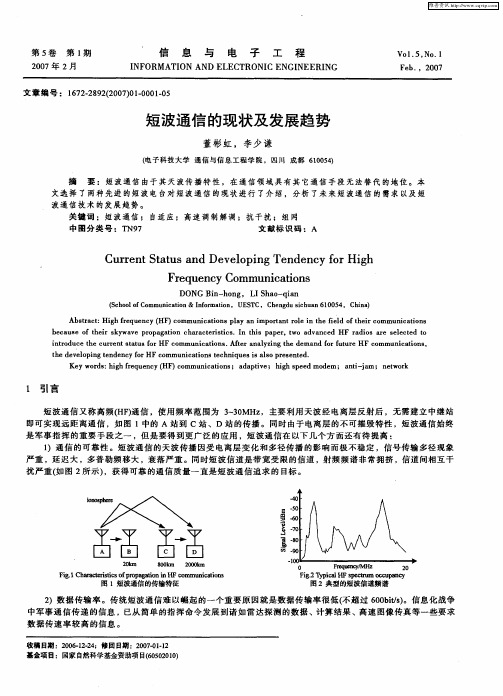
短波通信的现状及发展趋势
Cu r n t t s a d De e o i g Te d n y f rHi h r e tS a u n v l p n n e c o g F e u n y Co r q e c mmu i a i n nc t s o
A src: g e u n y( ) o b tat Hihf q e c HF c mmu iain lya otn l ntef l f h i c mm nct n r nc t spa ni r t oei edo er o u iai s o mp a r h i t o
DONG n— o Bi h ng. LIS a — a h o qin
(c o l f o S h o mmu iain&Ifr t n oC nc t o nomai ,UE T o S C,C e g usc u n6 0 5 h n d ih a 10 4,Chn ) ia
文 章 编 号 : 1 7 -8 22 0 )10 0 .5 6 22 9 (0 70 -0 10
短波通信 的现 状及发展趋势
董彬 虹 ,李 少 谦
( 子 科技 大 学 通 信 与 信 息 工 程 学 院 , I l成 都 60 5) 电  ̄J t t 104
摘 要 :短波通信 由于其 天波传 播特 性 ,在通 信领域 具有 其它通 信手段 无法替 代 的地 位。本 文 选 择 了 两 种 先 进 的短 波 电 台对 短 波 通 信 的 现 状 进 行 了介 绍 , 分 析 了 未 来 短 波 通 信 的 需 求 以及 短 波通信技 术 的发展趋势 。 关 键 词 : 短 波 通 信 ; 自适 应 ; 高 速 调 制 解 调 ;抗 干 扰 ; 组 网
HF-短波通信简介-EN
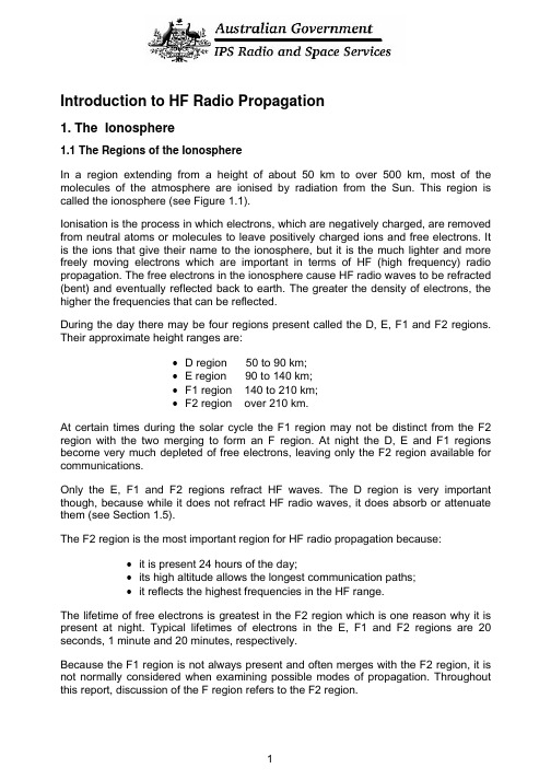
Introduction to HF Radio Propagation1. The Ionosphere1.1 The Regions of the IonosphereIn a region extending from a height of about 50 km to over 500 km, most of the molecules of the atmosphere are ionised by radiation from the Sun. This region is called the ionosphere (see Figure 1.1).Ionisation is the process in which electrons, which are negatively charged, are removed from neutral atoms or molecules to leave positively charged ions and free electrons. It is the ions that give their name to the ionosphere, but it is the much lighter and more freely moving electrons which are important in terms of HF (high frequency) radio propagation. The free electrons in the ionosphere cause HF radio waves to be refracted (bent) and eventually reflected back to earth. The greater the density of electrons, the higher the frequencies that can be reflected.During the day there may be four regions present called the D, E, F1 and F2 regions. Their approximate height ranges are:• D region 50 to 90 km;• E region 90 to 140 km;•F1 region 140 to 210 km;•F2 region over 210 km.At certain times during the solar cycle the F1 region may not be distinct from the F2 region with the two merging to form an F region. At night the D, E and F1 regions become very much depleted of free electrons, leaving only the F2 region available for communications.Only the E, F1 and F2 regions refract HF waves. The D region is very important though, because while it does not refract HF radio waves, it does absorb or attenuate them (see Section 1.5).The F2 region is the most important region for HF radio propagation because:•it is present 24 hours of the day;•its high altitude allows the longest communication paths;•it reflects the highest frequencies in the HF range.The lifetime of free electrons is greatest in the F2 region which is one reason why it is present at night. Typical lifetimes of electrons in the E, F1 and F2 regions are 20 seconds, 1 minute and 20 minutes, respectively.Because the F1 region is not always present and often merges with the F2 region, it is not normally considered when examining possible modes of propagation. Throughout this report, discussion of the F region refers to the F2 region.A l t i t u d e /(k m )Electron density/(electrons/cm 3)Figure 1.1 Day and night structure of the ionosphere.1.2 Production and Loss of ElectronsRadiation from the Sun causes ionisation in the ionosphere. Electrons are produced when solar radiation collides with uncharged atoms and molecules (Figure 1.2). Since this process requires solar radiation, production of electrons only occurs in the daylight hemisphere of the ionosphere.Loss of free-electrons in the ionosphere occurs when a free electron combines with a charged ion to form a neutral particle (Figure 1.3). Loss of electrons occurs continually, both day and night.freeelectronFigure 1.2 Free electron production in the ionosphereunchargedfreeatom(ion)electronFigure 1.3 Loss of free-electrons in the ionosphere.1.3 Observing the IonosphereThe most important feature of the ionosphere in terms of radio communications is its ability to reflect radio waves. However, only those waves within a certain frequency range will be reflected. The range of frequencies reflected depends on a number of factors (see Section 1.4).Various methods have been used to investigate the ionosphere, and the most widely used instrument for this purpose is the ionosonde (Figure 1.4). An ionosonde is a high frequency radar which sends very short pulses of radio energy vertically into the ionosphere. If the radio frequency is not too high, the pulses are reflected back towards the ground. The ionosonde records the time delay between transmission and reception of the pulses over a range of different frequencies.Echoes appear first from the lower E region and subsequently, with greater time delay, from the F1 and F2 regions. At night echoes are returned only from the F region since the E region is not present.IonospherepulseTx delta Rx deltaantenna antennaFigure 1.4 Ionosonde operation.Today, the ionosphere is “sounded” not only by signals sent up at vertical incidence but by oblique sounders which send pulses obliquely into the ionosphere with the transmitter and receiver separated by some distance. This type of sounder can monitor propagation on a particular circuit and observe the various modes being supported by the ionosphere (see Section 2.5). Backscatter ionosondes rely on echoes reflected from the ground and returned to the receiver, which may or may not be at the same site as the transmitter. This type of sounder is used for over-the-horizon radar.1.4 Ionospheric VariationsThe ionosphere is not a stable medium that allows the use of the same frequency throughout the year, or even over 24 hours. The ionosphere varies with the solar cycle, the seasons and during any given day.1.4.1 Variations due to the Solar CycleThe Sun goes through a periodic rise and fall in activity which affects HF communications; solar cycles vary in length from 9 to 14 years. At solar minimum, only the lower frequencies of the HF band will be supported (reflected) by the ionosphere, while at solar maximum the higher frequencies will successfully propagate (Figure 1.5). This is because there is more radiation being emitted from the Sun at solar maximum, producing more electrons in the ionosphere which allows the use of higher frequencies.96Sunspot no.foF2foF1foE Sunspot number CanberraYearF r e q u e n c y /(MH z )0481216889092949800020404080120160Sunspot number foF2foE foF1Figure 1.5 The relationship between solar cycles and maximum frequencies supported by E, F1 and F2 regions. Vertical lines indicate the start of each year. Note also the seasonal variations.There are other consequences of the solar cycle. Around solar maximum there is a greater likelihood of large solar flares occurring. Flares are huge explosions on the Sun which emit radiation that ionises the D region, causing increased absorption of HF waves. Since the D region is present only during the day, only those communication paths which pass through daylight will be affected. The absorption of HF waves travelling via the ionosphere after a flare has occurred is called a short wave fade-out (see Section 3.1). Fade-outs occur instantaneously and affect lower frequencies the most. If it is suspected or confirmed that a fade-out has occurred, it is advisable to try using a higher frequency. The duration of fade-outs can vary between about 10 minutes to several hours, depending on the duration and intensity of the flare.1.4.2 Seasonal VariationsE region frequencies are greater in summer than winter (see Figure 1.5). However, the variation inF region frequencies is more complicated. In both hemispheres, F region noon frequencies generally peak around the equinoxes (March and September). Around solar minimum the summer noon frequencies are, as expected, generally greater than those in winter, but around solar maximum winter frequencies tend to be higher than those in summer. In addition, frequencies around the equinoxes (March and September) are higher than those in summer or winter for both solar maximum and minimum. The observation of winter frequencies often being greater than those in summer is called the seasonal anomaly.1.4.3 Variations with LatitudeFigure 1.6 shows the variations in the E and F region maximum frequencies at mid-day (Day hemisphere) and mid-night (Night hemisphere) from the pole to the equator. During the day, with increasing latitude, the solar radiation strikes the atmosphere more obliquely, so the intensity of radiation and the daily production of free electrons decreases with increasing latitude. In the F region this latitude variation persists throughout the night due to the action of upper atmospheric wind currents from day-lit to night-side hemispheres (see for example, IPS HF Radio Propagation Course and Manual - .au/Products_and_Services/2/2).equatorial 2F E p o l e e q u a t o r mid-latitude trough e q u a t o rNight hemisphere Day hemisphere anomaly H i g h e s t u s a b l e f r e q u e n c y (M H z )121086402040608080604020Geomagnetic latitude (degrees)Figure 1.6 Latitudinal variations.Deviations from the general low to high latitude decrease are also apparent. Daytime F region frequencies peak not at the geomagnetic equator, but 15 to 20° north and south of it. This is called the equatorial anomaly. Also, at night, frequencies reach a minimum around 60° latitude north and south of the geomagnetic equator. This is called the mid-latitude trough. Communicators who require communications near the equator during the day and around 60° latitude at night, should be aware of these characteristics. For example, from Figure 1.6 one can see how rapidly the frequencies can change with latitude near the mid-latitude trough and equatorial anomaly, so a variation in the reflection point near these by a few degrees may lead to a large variation in the frequency supported.1.4.4 Daily VariationsFrequencies are normally higher during the day and lower at night (Figure 1.7). After dawn, solar radiation causes electrons to be produced in the ionosphere and frequencies increase rapidly to a maximum around noon. During the afternoon, frequencies begin falling due to electron loss and with darkness the D, E and F1 regions disappear. Communication during the night is by the F2 (or just F) region only and attenuation is very low. Through the night, maximum frequencies gradually decrease, reaching their minimum just before dawn.6158391202461012141618202224Local time/(hours)F r e q u e n c y /(M H z ) F1F2EFigure 1.7 E, F1 and F2 layer maximum frequencies throughout the day.1.5 Variations in AbsorptionAbsorption was discussed in section 1.4.1 in relation to solar flares. Whilst absorption is extremely high during a solar flare, a certain amount of D region absorption occurs all the time. Absorption in the D region varies with the solar cycle, being greatest around solar maximum. Signal absorption is also greater in summer and during the middle of the day (Figure 1.8). There is a variation in absorption with latitude, with more absorption occurring near the equator and decreasing towards the poles. Lower frequencies are absorbed the most so it is always advisable to use the highestfrequency possible, particularly during the day when absorption is greatest.summer (December 1980)winter (June 1980)V e r t i c a l a b s o r p t i o n /(d B )Time/(LT)5040302010100246812141618202224Figure 1.8 Daily and seasonal variations in absorption at Sydney, 2.2 MHz.Sometimes, high energy protons are ejected from the Sun during large solar flares. These protons move down the Earth’s magnetic field lines, into the polar regions and cause massive ionization of the polar D region leading to increased or total absorption of HF waves. This effect may last for as long as 10 days and is called a Polar Cap Absorption event (PCA) (see Section 3.2).1.6 Sporadic ESporadic E refers to the largely unpredictable formation of regions of very high electron density in the E region. Sporadic E may form at any time during the day or night occurring at altitudes of 90 to 140 km (the E region). It varies greatly in the area it covers (a few km to hundreds) and the time it persists for (minutes to many hours). Sporadic E can have a comparable electron density to the F region which means it can reflect the sort of high frequencies intended for F region communications. Sometimes a sporadic E layer is transparent and allows most of the radio wave to pass through it to the F region, however, at other times the sporadic E layer obscures the F region totally and the signal does not reach the F region and hence the receiver (sporadic E blanketing). If the sporadic E layer is partially transparent, the radio wave is likely to be reflected at times from the F region and at other times from the sporadic E region. This may lead to partial or intermittent transmission of the signal or fading (Figure 1.9).Sporadic E in the low and mid-latitudes occurs mostly during the daytime and early evening, and is more prevalent during the summer months. At high latitudes, sporadic E tends to form at night.Figure 1.9 Sporadic E formation (night or day) may result in communications via the F region being interrupted if the sporadic E electron density is high enough to reflect the wave.1.7 Spread FSpread F occurs when the F region becomes diffuse due to irregularities which scatter the radio wave. The received signal is the superposition of a number of waves reflected from different heights and locations in the ionosphere at slightly different times. At low latitudes, spread F occurs mostly during the night hours and around the equinoxes. At mid-latitudes, spread F is less likely to occur than at low and high latitudes and is more likely to occur at night and in winter. At latitudes greater than about 40°, spread F tends to be a night time phenomenon, appearing mostly around the equinoxes, while around the magnetic poles, spread F is often observed both day and night. At all latitudes there is a tendency for spread F to occur when there is a decrease in F region maximum frequencies (reduced electron density). That is, spread F is often associated with ionospheric storms (see Section 3.3).2. HF Communications2.1 Types of HF PropagationHigh Frequency (3 to 30 MHz) radio signals can propagate to a distant receiver, Figure 2.1, via the:•ground wave: near the ground for short distances, up to 100 km over land and 300 km over sea. Attenuation of the wave depends on antenna height, polarisation, frequency, ground types, terrain and/or sea state;•direct or line-of-sight wave: this wave may interact with the earth-reflected wave depending on terminal separation, frequency and polarisation;•sky wave: reflected by the ionosphere; all distances.2.2 Frequency Limits of Sky WavesNot all HF waves are reflected by the ionosphere; there are upper and lower frequency bounds for communications between two terminals. If the frequency is too high, the wave will pass straight through the ionosphere. If it is too low, the strength of the signal will be very low due to absorption in the D region. The range of usable frequencies will vary:•throughout the day;•with the seasons;•with the solar cycle;•from place to place;The upper limit of frequencies varies mostly with the above factors, while the lower limit also depends on receiver site noise, antenna efficiency, transmitter power, E layer screening (Section 2.6) and absorption by the ionosphere.Figure 2.1 Types of HF propagation.2.3 The Usable Frequency RangeFor any circuit there is a Maximum Usable Frequency (MUF) which is determined by the state of the ionosphere in the vicinity of the reflection points and the length of the circuit. The MUF is reflected from the maximum electron density within a given layer of the ionosphere. Therefore, frequencies higher than the MUF for a particular region will penetrate through that region entirely. During the day it is possible to communicate via both the E and F layers using different frequencies. The highest frequency supported by the E layer is the EMUF, while that supported by the F layer is the FMUF.The F region MUF in particular varies greatly throughout the day, seasonally and with the solar cycle. Historical data collected over many years displays the full range of these variations for a given location. The historical data is averaged and organised to give a MUF for every hour of the day (24 values), for each month of the year. These can also be adjusted for the solar cycle. MUFs are quoted as a statistical range with the “lower decile” (also called the Optimum Working Frequency OWF) working 90% of the time, the “median” MUF working 50% of the time and the “upper decile” MUF working just 10% of the time. IPS predictions usually cover a period of one month, so the OWF for a given hour, should provide successful propagation 90% of the time or 27 days of the that month. The median MUF should provide communications on 15 days of the month and the upper decile MUF on just 3 days of the month. The upper decile MUF is the highest frequency of the range and is most likely to penetrate the ionosphere, thus only working 10% of the time (Figure 2.2).Figure 2.2 Range of usable frequencies. If the frequency, f, is close to the ALF then the wave may suffer absorption in the D region. If the frequency is above the EMUF then propagation is via the F region. Above the FMUF the wave is likely to penetratethe ionosphere.The statistical MUFS described above correspond to “quiet background” conditions. With short-term variations in solar activity however, away from quiet background levels, usable frequencies change. This needs to be reflected in MUF predictions and one ofthe roles of the Australian Space Forecast Centre (ASFC) at IPS is to modify the historical MUFS to reflect the real-time observed space-weather conditions. Sophisticated techniques have been developed at IPS over many years to combine the effects of observed space-weather conditions with historically averaged data to provide detailed and accurate predictions of ionospheric conditions.D region absorption of HF radio waves increases rapidly with decreasing frequency. The D region thus places a lower limit on the frequencies which can be used for ionospheric propagation. This limit is called the Absorption Limiting Frequency (ALF). The ALF is significant only for circuits with reflection points in the sunlit hemisphere. At night, the ALF falls to zero, allowing frequencies which are not usable during the day to successfully propagate.2.4 Hop LengthsThe hop length is the ground distance covered by a radio signal after it has been reflected once from the ionosphere and returned to Earth (Figure 2.3). The maximumhop length is set by the height of the ionosphere and the curvature of the Earth. For Eand F region heights of 100 km and 300 km, the maximum hop lengths are about 1800km and 3200 km, respectively (corresponding to an elevation angle of around 4°).Distances greater than these will require more than one hop. For example, a distance of 6100 km will require a minimum of 4 hops by the E region and 2 hops via the F region. More hops are required again with larger antenna elevation angles.Figure 2.3 Hop lengths based upon an antenna elevation angle of 4° and heights for the E and F layers of 100 km and 300 km, respectively.2.5 Propagation ModesThere are many paths by which a sky wave may travel from a transmitter to a receiver. The mode reflected by a particular layer which requires the least number of hops between the transmitter and receiver is called the first order mode. The mode that requires one extra hop is called the second order mode, and so on. For a circuit with a path length of 5000 km, the first order F mode has two hops (2F), while the second order F mode has three hops (3F). The first order E mode has the same number of hops as the first order F mode. If this results in a hop length of greater than 2050 km, which corresponds to an elevation angle of 0°, then the E mode is not possible.Simple modes are those propagated by one region, say the F region. IPS predictions are made only for these simple modes (Figure 2.4). More complicated modes consisting of combinations of reflections from the E and F regions, ducting and chordal modes are also possible (Figure 2.5).Figure 2.4 Examples of simple propagation modes.Chordal modes and ducting involve a number of reflections/refractions from the ionosphere without intermediate reflections from the Earth. There is a tendency to think of the regions of the ionosphere as being smooth, however, the ionosphere undulates and moves, with waves passing through it which affects the refraction of radio signals. When ionospheric layers tilt chordal and ducted modes may occur. Ionospheric tilting is more likely near the equatorial anomaly, the mid-latitude trough and in the sunrise and sunset sectors of the globe. When these types of modes occur, signals can be strong since the wave spends less time traversing the D region or being attenuated by ground reflections.Figure 2.5 Complex propagation modes.Because of the high electron density of the daytime ionosphere around 15° from the magnetic equator (near the equatorial anomaly), trans-equatorial paths can propagate on very high frequencies. Any tilting of the ionosphere in this region may result in chordal modes (see Figure 2.5) which produce good signal strength over very long distances.Ducting may also result if tilting occurs and the wave becomes trapped between reflecting regions of the ionosphere (see Figure 2.5). This is most likely to occur in the equatorial ionosphere, near the auroral zone and mid-latitude trough. Disturbances to the ionosphere, such as travelling ionospheric disturbances (see Section 2.9), may also initiate ducting and chordal modes.2.6 E Layer ScreeningFor daytime communications via the F region, the lowest usable frequency via the one hop F mode (1F) is dependent upon the presence of the E region. If the operating frequency is below the two hop EMUF, then the signal will propagate via the 2E mode rather than the 1F mode (Figure 2.6). This is also because the antenna elevation angles of the 1F and 2E modes are similar.Figure 2.6 E layer screening occurs if communications are intended by the 1F mode but the operating frequency is close to or below the EMUF for the 2E mode. Note that the 2 hop E mode travels twice as many times through the D region.A sporadic E layer may also screen a HF wave from the F region. Sometimes sporadic E can be quite transparent, allowing most of the wave to pass through it. At other times it will partially screen the F region leading to a weak or fading signal, while at other times sporadic E can totally obscure the F region with the result that the signal does not arrive at the receiver (Figure 1.9).2.7 Frequency, Range and Elevation AngleFor HF propagation path, there are three dependent variables:• frequency;•range or path length;•antenna elevation angle.The diagrams below illustrate the possible changes to the ray paths when each of these is fixed in turn.Figure 2.7: Elevation angle fixed:•As the frequency is increased toward the MUF, the wave is reflected higher in the ionosphere and the range increases; paths 1 and 2•Exactly at the MUF, the maximum range is reached; path 3•Above the MUF, the wave penetrates the ionosphere; path 44. frequency too highFigure 2.7 Elevation angle fixed.Figure 2.8: Path length fixed (point-to-point circuit):•As the frequency is increased towards the MUF, the wave is reflected from higher in the ionosphere. To maintain a circuit of fixed length, the elevation angle must therefore be increased (paths 1 and 2)• At the MUF, the critical elevation angle is reached (path 3). The critical elevation angle is the highest elevation angle for a particular frequency.•Above the MUF, the ray penetrates the ionosphere (path 4).Figure 2.8 Path length fixed.Figure 2.9: Frequency fixed:•At low elevation angles the path length is greatest (path 1);•As the elevation angle is increased, the path length decreases and the ray is reflected from higher in the ionosphere (paths 2 and 3);•If the elevation angle is increased beyond the critical elevation angle for that frequency then the wave penetrates the ionosphere and there is an area around the transmitter within which no sky wave communications can be received (path 4). To communicate within this so called “skip zone”, the frequency must be lowered.•If a signal of a certain frequency is reflected when vertically incident on the ionosphere, then there is no skip zone. The vertically incident maximum frequency is referred to as f0F2 and is a key ionospheric parameter.Figure 2.9 Frequency fixed.2.8 Skip ZonesSkip zones can often be used to advantage if it is desired that communications are not heard by a particular receiver. Selecting a frequency which puts a receiver in the skip zone and out of reach of the ground wave makes it unlikely that it will receive the communications. However, factors such as sidescatter, where reflection from the Earth outside the skip zone results in the wave transmitting into the skip zone may affect the reliability of this.Skip zones vary in size during the day, with the seasons, and with solar activity. During the day, solar maximum and around the equinoxes, skip zones generally are smaller in area. The ionosphere during these times has increased electron density and so is able to support higher frequencies.2.9 FadingMultipath fading results when a number of modes propagate from transmitter to receiver, which have variations in phase and amplitude. See for example, Figure 2.4. The signal travels by a number of paths simultaneously which may interfere at the receiver, causing fading.Disturbances known as Travelling Ionospheric Disturbances (TID), may cause a region to be tilted, resulting in the signal being focussed or defocused (Figure 2.10). Fading periods of the order of 10 minutes or more can be associated with these structures. TIDs travel horizontally at 5 to 10 km/minute with a well defined direction of travel andaffect higher frequencies first. Some originate in auroral zones following an event on the Sun and these may travel large distances. Others originate in lower atmospheric weather disturbances. TIDs may cause variations in phase, amplitude, polarisation and angle of arrival of a radio wave.Polarisation fading results from changes to the polarisation of the wave along the propagation path with the receiving antenna being unable to receive parts of the signal. This type of fading can last for a fraction of a second to a few seconds.Skip fading often occurs around sunrise and sunset when the ionosphere is at its most unstable. If the operating frequency is close to the MUF and the receiving antenna is positioned close to the boundary of the skip zone then signal will fade in and out with fluctuations in the ionosphere.Figure 2.10 Focussing and defocussing effects caused by travelling ionospheric disturbances (TIDs).2.10 NoiseRadio noise arises from internal and external origins. Internal or thermal noise is generated in the receiving system and is usually neglig ible for a good quality receiver when compared to external sources of noise. External radio noise originates from natural (atmospheric and galactic) and man-made (environmental) sources. Atmospheric noise, which is caused by thunderstorms, is normally the major contributor to radio noise in the HF band and will especially degrade circuits passing through the day-night interface. Atmospheric noise is greatest in the equatorial regions and decreases with increasing latitude. Its effect is also greater on lower frequencies so isusually more of a problem around solar minimum and at night when lower frequencies are needed.Galactic noise arises from our galaxy. Since only the highest frequencies will pass through the ionosphere (from above) galactic noise only effects high frequencies.Man-made noise results from any large currents and voltages such as ignition systems, neon signs, electrical cables, power transmission lines and welding machines. This type of noise depends on the technology used by the society and its population. Interference may be intentional (jamming), due to propagation conditions or the result of others operating on the same frequency.Man-made noise tends to be vertically polarised, so selecting a horizontally polarised antenna may help in reducing man-made noise. Using a narrower bandwidth, or a directional receiving antenna (with a lobe in the direction of the transmitting source and a null in the direction of the unwanted noise source), will also aid in reducing the effects of noise. Selecting a site with a low noise level and determining the major noise sources are important factors in establishing a successful communications system.2.11 VHF and 27 MHz PropagationVHF and 27 MHz are used for line-of-sight or direct wave communication, for example, ship-to-ship or ship-to-shore. The frequency bands are divided into channels and one channel is usually as good as the next. This is in contrast to medium frequency (MF: 300 kHz to 3 MHz) and HF where the choice of a frequency channel may be crucial for good communications.Because VHF and 27 MHz operate mainly by line-of-sight, it is important to mount the antenna as high as possible and free from obstructions. Shore stations are usually on the tops of hills to provide maximum range, but even the highest hills do not provide coverage beyond about 45 nautical miles (80 km), because of the Earth’s curvature. Antennas for VHF and 27 MHz should usually concentrate radiation at low angles (towards the horizon) as except when communicating with aircraft, radiation directed at high angles will pass over the receiving antenna. VHF and 27 MHz do not usually suffer from atmospheric noise except during severe electrical storms. Interference mainly results from many users wishing to use the limited number of channels, and this can bea significant problem in densely populated areas.27 MHz and the lower frequencies in the VHF band can, at times, propagate over large distances, well beyond the normal line-of-sight limitations. There are three ways that this can take place:•around solar maximum and during the day, the ionospheric F region will often support long range sky wave communications on 27 MHz and above;•sporadic E layers can often support 27 MHz and lower frequency VHF propagation over circuits of about 500 to 1000 nautical miles (1000 to 2000 km) in length. This kind of propagation is most likely to occur at mid-latitudes, during the daytime in summer;•27 MHz and VHF can also propagate by means of temperature inversions (ducting) at altitudes of a few kilometres. Under these conditions, the waves are gradually。
短波通信原理
短波通信原理
短波通信是一种利用短波频段进行无线传输的通信技术。
它的原理是通过调频调幅的方式,将信息信号转换为高频的短波信号,然后通过天线进行传输。
短波信号在空间中以电磁波的形式传播,经过反射和折射等过程,能够覆盖长距离的传输距离。
短波通信的频率范围一般为3MHz到30MHz,这个频段在电
离层中的传播特性比较好,可以实现远距离的通信。
与其他频段的无线通信相比,短波通信具有以下优点:
1. 长距离传输:由于短波信号的传输特性,它在空间中的传播距离较远,能够覆盖较大的通信范围,特别适用于遥远地区的通信需求。
2. 抗干扰能力强:短波信号在传输过程中相对不容易受到天气、建筑物等因素的干扰,因此能够更好地保证通信的稳定性和可靠性。
3. 灵活性高:短波通信设备相对较小、轻便,可以快速搭建和移动,适应各种复杂环境下的通信需求。
4. 自主性强:短波通信不依赖于任何地面基础设施,可以独立进行通信,特别适用于紧急情况下的通信应急需求。
短波通信在广播、航空、海陆交通等领域都有广泛应用。
虽然现在有很多其他频段的无线通信技术可以实现更高的传输速率
和更大的带宽,但短波通信由于其独特的传输特性和广阔的覆盖范围,仍然是许多远距离通信需求的首选技术。
短波通信原理

短波通信原理
短波通信是一种无线电通信方式,利用短波无线电波在大气中的反射和折射特性进行远距离传播。
短波无线电波的频率范围在3kHz到30MHz之间,可以在地面与大气层之间多次反射和折射,从而实现远距离通信。
其工作原理大致如下:通过改变发射机的电压来产生电磁波,这些电磁波被传输到空气中。
接收机捕捉到这些电磁波,并通过放大和解调的过程将信息转换回电信号。
由于短波无线电波可以穿越大气层,因此短波通信可以在大范围内传输信息。
然而,短波通信也有一些局限性,如受地形的影响和易受干扰。
为了克服这些限制,人们可以使用不同的天线或调整频率来提高短波通信的性能。
以上内容仅供参考,如需更多信息,建议查阅相关文献或咨询专业人士。
短波跳频电台的工作原理及应用领域分析
短波跳频电台的工作原理及应用领域分析短波跳频(HFH)是一种无线通信技术,通过频率跳跃的方式传输数据。
本文将详细介绍短波跳频电台的工作原理,并分析其应用领域。
一、短波跳频电台的工作原理短波跳频电台是一种采用频率跳跃技术的无线通信设备。
它通过在一定的频率范围内快速随机跳跃而实现通信。
具体工作原理如下:1. 频率跳跃序列生成短波跳频电台通过电路生成一系列的频率跳跃序列,这个序列由伪随机数生成器产生。
伪随机数的特点是看似随机,但实际上具有一定规律,这样可以使得频率跳跃更有效率。
2. 跳频调谐和发送根据所生成的频率跳跃序列,短波跳频电台在每个时间段内选择对应的频率进行调谐,并将待发送的数据通过无线电信号发送出去。
这样,短波跳频电台就能够在不同的频率上快速切换发送信号。
3. 接收和解调接收端的短波跳频电台也同样根据预定的频率跳跃序列进行调谐,接收无线信号并解调。
解调后的信号可以还原为原始的数据,从而实现通信。
二、短波跳频电台的应用领域短波跳频电台具有一定的特点和优势,其应用领域十分广泛。
以下是几个典型的应用领域分析:1. 军事通信短波跳频电台在军事通信领域具有重要的地位。
它可以有效抵抗干扰和窃听,提供更加安全可靠的通信传输。
军队可以利用短波跳频电台实现情报传递、指挥控制和士兵之间的通信等功能。
2. 紧急救援在自然灾害或紧急救援场景中,通常无法依赖传统的通信设备。
短波跳频电台因其传输范围广、抗干扰能力强的特点,被广泛应用于紧急救援通信中。
它可以在恶劣环境下实现与救援人员的远距离通信,提供重要的信息传递,并协助救援行动迅速展开。
3. 远距离通信短波跳频电台能够传输的范围广,能够在大规模地理区域内进行通信。
这使得它成为远距离通信的理想选择。
例如,在山区或海洋上使用短波跳频电台进行通信,能够有效地克服地形和距离因素,保持通信畅通。
4. 无线电控制系统短波跳频电台在无线电控制系统中有广泛应用。
例如,在工业自动化领域,利用短波跳频电台可以实现远程监控和控制,提高生产效率和安全性。
海上超短波通信距离分析
海上超短波通信距离分析海上超短波通信是船舶通信中最常用的一种通信方式,其具有通信距离远、抗干扰能力强等特点,有效的保障了海上通信的顺畅性。
但是,由于不同频率的海上超短波通信在不同的气象条件下,其通信距离会有所差别,因此,在使用海上超短波通信时,需要对其通信距离进行分析。
在海上超短波通信中,不同频率的电波具有不同的传播距离。
一般而言,频率越高,波长越短,传播距离也就越短。
以海上通信中常用的海事电台为例,其分别包括了LF、MF、HF、VHF和UHF等多种频率段,其通信距离如下:1. LF频率段:通常在30kHz-300kHz之间,适用于近海和岸边通信,其通信距离在100-300海里之间。
2. MF频率段:通常在300kHz-3000kHz之间,适用于一些较远的通信,其通信距离在300-1000海里之间。
3. HF频率段:通常在3MHz-30MHz之间,是最常用的频段之一,适用于中远距离通信,其通信距离在1000-3000海里之间。
4. VHF频率段:通常在30MHz-300MHz之间,适用于近距离的通信,其通信距离在30海里左右。
5. UHF频率段:通常在300MHz-3GHz之间,适用于短距离的通信,其通信距离在10海里左右。
需要注意的是,上述通信距离只是估算值,在具体的通信中,风浪和气象条件等因素也会对通信距离产生影响。
因此,在实际使用海上超短波通信时,需要进行不同频率段的测试,以确定其具体的通信距离。
在进行海上超短波通信时,还需要注意到信号衰减的问题。
随着距离的增加,海上超短波的信号强度会逐渐下降,直到无法接收。
因此,在长距离通信时,需要注意信号强度的检测和增强,以保证通信的质量。
总之,海上超短波通信是保证海上通信质量的重要手段之一。
在实际的应用中,需要对不同频率段的通信距离进行分析,以确定最佳的通信频率和通信距离,以保证海上通信的成功和顺畅。
在实际使用海上超短波通信时,需要对不同频率段的通信距离进行分析。
HF短波9个波段频率详细介绍(业余无线电爱好者-火腿入门)
HF部分包括9个不同的波段,范围从1.8MHz到29.7MHz,它们通常也称为160米到10米波段。
10米:频率范围是28.0-29.7MHz,一般只有在白天和傍晚才有远程传播。
这个波段一旦开通,可以有非常好的通信效果,而且对机器功率要求低,天线的尺寸也小。
29.6MHz是国际上都知名的中国FM频率。
自从1995-1996年中国无线电运动协会开展的10米FM实验活动以来,这个波段就一直保持非常的活跃。
10米波段是允许FM的唯一HF波段,当然根据你的操作权限你也可以使用SSB或者CW。
它也是唯一对四级操作证书持有者开放的HF波段。
12米:12米波段于1985年才对火腿开放,范围是24.890MHz到24.990MHz。
它与10米波段相距很近,传播特性也十分相似。
这一波段相对不算拥挤。
不过正如你所想的那样,太阳黑子的活动对其会造成影响——10米波段也是如此。
15米:15米波段的范围是21.000MHz到21.450MHz,与10米波段的不可靠传播特性不同,15米波段相对稳定而且也适合远程通信。
中国火腿聚集在21.400MHz以USB方式通信。
21.110-21.200MHz则聚集了大量的新手CW操作者。
21.200-21.300是国际的SSB通信波段。
17米:17米波段的范围是18.068MHz到18.168MHz,是最新开放的波段。
这一波段具有全球通信的潜力,虽然范围狭窄但是很整齐。
20米:20米波段对于那些热衷于全球远程通连的火腿们无疑是最好的选择。
范围是14.000到14.350MHz。
很多火腿用这一波段通连了超过100个国家。
特别是傍晚和周末,你会在这里听到很多使用大功率和八木天线的高配置电台,不过它台干扰也相应多一些。
中国HAM 的常用频率是14.270MHz USB,老业余爱好者们的常用频率则是14.180MHz USB。
30米:30米波段从10.100MHz到10.150MHz,在HF波段中范围最小。
短波通信发展综述教学内容

短波通信发展综述邹光辉短波通信又称高频(HF)通信,使用频率范围为3-30MHz,主要利用天波经电离层反射后,无需建立中继站即可实现远距离通信。
同时由于电离层的不可摧毁特性,短波通信始终是军事指挥的重要手段之一。
由于短波通信在军事通信上的不可替代性,从20 世纪80 年代初, 短波通信进入了复兴和发展的新时期。
许多国家加速了对短波、超短波通信技术的研究与开发,推出了许多性能优良的设备和系统。
短波通信再次占领一定的地位, 随着技术的进步, 对于通信的一些缺点, 不少已找到克服和改进的办法。
短波通信的可靠性、稳定性、通信质量和通信速率都已提高了一个新水平。
一、由单一自适应技术向全自适应技术方向发展短波通信存在着短波信道的时变色散特性和高电平干扰的弱点。
因此, 为了提高短波通信的质量, 最根本的途径是“实时地避开干扰, 找出具有良好传播条件的无噪声信道”。
完成这一任务的关键是采用自适应技术。
所谓自适应, 就是能够连续测量信号和系统变化, 自动改变系统结构和参数, 使系统能自适应环境的变化和抵御人为干扰。
因此短波自适应的含义很广。
现已发展的自适应技术有自适应选频与信道建立技术、功率自适应技术、传输速率自适应技术、自适应调制解调技术、自适应分集技术、自适应信道均衡及辨识技术、自适应编码技术、自适应调零天线技术。
传统意义上的自适应主要是指频率自适应, 是以事实信道估值为基础, 采用自动链路建立和链路质量分析技术, 因此也称为实时选频技术。
在未来信息时代, 网络数据通信将成为主要的通信方式, 但是单一的频率自适应还无法满足网络数据通信的要求, 由于短波通信中各种新技术的出现, 特别是分组交换和各种自适应短波通信技术的发展, 为短波数据网的发展打下了基础, 频率自适应技术可与其他自适应功能综合构成全自适应短波通信系统。
未来通信的需求促进了短波自适应通信系统正向全自适应技术的方向发展。
二、由窄带低速数据通信向宽带高速数据通信发展针对短波通信存在的保密( 或隐蔽) 性不强、抗干扰能力差的弱点, 以及电磁环境的特点和规律, 为了提高短波通信干扰能力,发展起来了短波通信电子防御技术。
短波通信原理
短波通信原理
短波通信是一种通过使用较短波长的无线电信号进行远距离通信的方法。
它是一种非常重要的通信方式,尤其在没有其他通信设施或网络可用时。
短波通信的原理在于利用大气中的电离层反射电磁波的特性。
信号会从发送端发出后被电离层所反射,然后再经过一段距离后再次反射回地面。
这样一来,信号就可以越过较长的距离进行通信。
这种反射会随着电离层数量和离地距离的不同而发生。
为了更好地利用短波通信,需要根据具体情况选择合适的发射机功率、天线方向和极化方式等参数。
这些参数的选择会受到天气条件、电离层活动和地球表面形态等因素的影响。
短波通信具有一些优点,例如可靠性较高、成本较低和覆盖范围广等。
它可以用于军事通信、无线电广播、天气预报、航空通信等各种应用领域。
然而,短波通信也存在一些局限性。
由于电离层的波动性和天气条件的变化,信号的传播会受到很大的影响。
此外,短波频段的带宽较窄,传输速率较低,无法支持大量数据的传输。
总的来说,短波通信是一种通过利用电离层反射特性进行远距离通信的方法。
虽然它有一些限制,但是在特定应用场景下仍然是一种非常有用的通信方式。
短波通信的发展历程

短波通信的特点短波按照国际无线电咨询委员会(CCIR,现在的ITU-R),的划分是指波长在l00m~l0m,频率为3MHz~30MHz的电磁波。
利用短波进行的无线电通信称为短波通信,又称高频(HF)通信。
实际上,为了充分利用短波近距离通信的优点,短波通信实际使用的频率范围为1。
5MHz~30MHz。
短波通信的发展历程自从1921年发生在意大利罗马的一次意外事故,短波被发现可实现远距离通信以来,短波通信迅速发展,成为了世界各国中、远程通信的主要手段,被广泛地用于政府、军事、外交、气象、商业等部门,用以传送电报、电话、传真、低速数据和图像、语音广播等信息。
在卫星通信出现以前,短波在国际通信、防汛救灾、海难救援以及军事通信等方面发挥了独特的重要作用。
短波通信可以利用地波传播,但主要是利用天波传播。
地波传播的衰耗随工作频率的升高而递增,在同样的地面条件下,频率越高,衰耗越大.利用地波只适用于近距离通信,其工作频率一般选在5MHz以下。
地波传播受天气影响小,比较稳定,信道参数基本不随时间变化,故地波传播信道可视为恒参信道。
天波是无线电波经电离层反射回地面的部分,倾斜投射的电磁波经电离层反射后,可以传到几千千米外的地面.天波的传播损耗比地波小得多,经地面与电离层之间多次反射(多跳传播)之后,可以达到极远的地方,因此,利用天波可以进行环球通信。
天波传播因受电离层变化和多径传播的严重影响极不稳定,其信道参数随时间而急剧变化,因此称为变参信道.天波不仅可以用于远距离通信,而且还可以用于近距离通信。
在地形复杂,短波地波或视距微波受阻挡而无法到达的地区,利用高仰角投射的天波可以实现通信。
与卫星通信、地面微波、同轴电缆、光缆等通信手段相比,短波通信也有着许多显著的优点:1)短波通信不需要建立中继站即可实现远距离通信,因而建设和维护费用低,建设周期短;2)设备简单,可以根据使用要求固定设置,进行定点固定通信。
也可以背负或装入车辆、舰船、飞行器中进行移动通信;3)电路调度容易,临时组网方便、迅速,具有很大的使用灵活性;4)对自然灾害或战争的抗毁能力强。
短波通信新技术范文.doc
短波通信新技术范文摘要:短波通信有自身独特的优点,广泛应用于政府、军事、外交、气象、商业等部门,但也存在固有的缺点。
本文介绍了短波自适应频率、DSP数字消噪、无盲区通信以及短波组网等新技术的一般原理、性能特点、产品及相关情况,分析了短波通信开展需求和趋势,为同行提供参考、借鉴。
关键词:短波;自适应频率;DSP数字消噪;无盲区通信一、引言短波通信又称高频(HF)通信是指在3M—30MHz频段范围内,通过电离层反射进行远距离传输或通过地波进行近距离传输的一种通信手段。
短波通信与其它通信方式相比,有自身的优点:通信距离远,在数千公里范围内短波不需要转发器就可进行超视距通信;抗毁性强,短波是唯一不受网络枢纽和有源中继体制约的远程通信手段,一旦发生战争或灾害,各种通信网络都可能受到破坏,卫星也可能受到攻击,但电离层具有不可摧毁性;接收设备简单,对于播送业务,接收端只需要配置短波接收机即可。
正是由于这些优点,短波通信一直是世界各国中、远程通信的主要手段,广泛应用于政府、军事、外交、气象、商业等部门。
短波通信也存在固有的缺点:多径衰落现象严重,短波在电离层反射的传播过程中,信号振幅变化达几十倍,甚至几百倍;盲区内通信困难,一般来说,短波通过地波传播最远距离约为30公里,而天波从电离层第一次反射落地的最短距离约为100公里,因此30公里至100公里的区域,形成了短波通信的盲区;电离层暴变严重干扰短波通信,电离层参数受太阳等外界影响,F2层的电子浓度、有效高度以及电离层结构将产生不规那么变化,使电离层的最高可用频率降低,甚至完全破坏而使短波通信中断。
近年来,随着短波通信在航空导航、水上平安、抢险救灾、军事通信等方面的广泛应用,其稳定性和可靠性差的缺点日益突出,给短波通信研究带来了很大的挑战的同时,短波通信新技术开展也面临着前所未有的机遇。
二、自适应频率短波信道(电离层)是一种典型时变色散信道,其路径损耗、时延散布、噪声和干扰等都随频率、地点、季节、昼夜的变化不断变化,因此,短波通信中工作频率是不能任意选择的。
- 1、下载文档前请自行甄别文档内容的完整性,平台不提供额外的编辑、内容补充、找答案等附加服务。
- 2、"仅部分预览"的文档,不可在线预览部分如存在完整性等问题,可反馈申请退款(可完整预览的文档不适用该条件!)。
- 3、如文档侵犯您的权益,请联系客服反馈,我们会尽快为您处理(人工客服工作时间:9:00-18:30)。
短波通信
HF:高频,所指的就是短波波段1600千周--30000千周(180公尺--10公尺)FM:调频,是一种通信方式
调频(FM),就是高频载波的频率不是一个常数,是随调制信号而在一定范围内变化的调制方式,其幅值则是一个常数。
与其对应的,调幅就是载频的频率是不变的,其幅值随调制信号而变。
一般干扰信号总是叠加在信号上,改变其幅值。
所以调频波虽然爱到干扰后幅度上也会有变化,但在接收端可以用限幅器将信号幅度上的变化削去,所以调频波的抗干扰性极好,用收音机接收调频广播,基本上听不到杂音。
使载波频率按照调制信号改变的调制方式叫调频。
已调波频率变化的大小由调制信号的大小决定,变化的周期由调制信号的频率决定。
已调波的振幅保持不变。
调频波的波形,就像是个被压缩得不均匀的弹簧,调频波用英文字母FM表示。
载波的瞬时频率按调制信号的变化而变,但振幅不变的调制方式。
载波经调频后成为调频波。
用调频波传送信号可避免幅度干扰的影响而提高通信质量。
广泛应用在通信、调频立体声广播和电视中。
我们习惯上用FM来指一般的调频广播(76-108MHz,在我国为87-108MHz、日本为76-90MHz),事实上FM也是一种调制方式,即使在短波范围内的
27-30MHz之间,做为业余电台、太空、人造卫星通讯应用的波段,也有采用调频(FM)方式的。
FM radio即为调频收音机。
FM调频即收音机功能。
作为MP3的一项附加功能,从实用角度来说,现在的MP3这方面做得并不很出色,应该说还不如普通的收音机,在接收范围、精度等等方面还都有差距,只能说是一个有益的补充。
当然,如果你注重这个功能的话,也有做得不错的产品。
而在具体机型上,针对FM,不同产品还有细分,是否可以保存选定的频道、可以保存多少个频道、立体声和普通声道可以自己设定还是由机器来设定。
SSB:单边带话通信
在短波(HF)段一般采用占用频带较窄的单边带话,简称SB方式(Single Side Band)。
在通信中双方直接利用语言,主要是英语明语以及"通信用Q简语"和"缩语"交谈。
单边带话又分上边带(USB)和下边带(LSB)
一般通信系统中,载波音频信号调制后,包含载波频率和上,下两个边带,这两个边带均能用来传输信息。
通常传递信号,仅需要一个边带就可以了,但在一般的通信系统中,往往把载波频率和上,下边带一起发送去,这样在载波和另一边带中消耗了发射功率中的大部分功率,而且还要占用较宽的通信频带。
为了提高通信效率和节约通信频带,在通信时,可将载波和另一边带去掉,只发送一个边带,这种通信方式就称为单边带通信。
根据国际协议,短波通信必须使用单边带调幅方式(SSB),只有短波广播节目可以使用双边带调幅方式(AM)。
因此,国内外使用的短波电台都是单边带电台。
单边带通信的优点是:节约频带,节省功率,由于单边带发射机不发送载频,提高了保密性。
单边带通信的缺点是设备比较复杂。
发送和接收调幅信号的两个边带中的一个边带信号的无线电通信设备。
通常由发信机、收信机、天线、电源和终端设备等组成。
只用一个边带(上边带或下边带)传送信息的制度,称为“原型单边带制”。
把上下边带各传输不同信息的制度,称为“独立边带制”。
军用单边带电台,主要采用独立边带制,通常每个3千赫的边带,可传送一路话或多路报。
单边带通信技术于1915年发明,1923年进行了横跨大西洋通信试验,1933年以后为大多数远洋通信所采用。
从1954年起,单边带电台在军用无线电通信系统中迅速发展,逐步取代了普通的调幅电台。
单边带电台在传送话音信号时,话音信号和频率合成器产生的高稳定度的低载频信号,同时加到发信机的调制器上,经调制器的作用,产生上下边带信号并抑制载频,再经滤波器把某一边带滤掉,只让另一边带的信号搬移到较高的工作频率上,并加以放大,送至天线发射出去。
收信机将天线接收的射频单边带信号,搬回到较低的频率上,并加以放大,送入单边带解调器。
在解调器中,必须同时加入低载频信号,将原话音信号还原出来。
单边带电台在传送电报信号时,主要采用移频键控的方式。
移频键控信号产生器,可作为发信机的一个部件装入机内,也可作为外附的电报终端设备,它的作用是将键控信号,分别转变为不同频率的无线电信号发出。
为接收移频键控信号,单边带接收机内需有移频键控信号接收器或外附的电报终端设备,其作用是将接收到的移频键控信号恢复成相应的键控信号。
综上所述,收音机的单边带接收,主要接收的是通信信号和语音通信,不是普通意义上的无线电广播。
