MA4FCP200中文资料
PV200说明书
●希望 对于本手册中的内容,我们虽然已考虑周全,但如 果您有疑问或发现错误之处,麻烦您与本公司联系。
i
Hale Waihona Puke 录1 对位 .......................................................... 5
1.1 菜单 ........................................................................6 1.2 主要设定内容 .........................................................7
6.2 品种>对位>自学习 .......................................... 121 6.2.1 平台移动量 ................................................. 121 6.2.2 自学习数据 ................................................. 122
PFC200中文资料
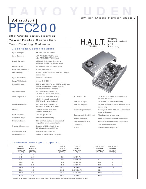
* Select one output each for Main, Aux 1, Aux 2, and Aux 3 from the available outputs listed.
元器件交易网
Model
PFC200
Options
Fan Supply (12Vdc, 150mA) Fan/Cover DC OK PF Invert DC OK Invert Pre-Load Gold Signal Pins Remote Invert Metric Mounting Molex Connectors Thermal Latch-Off Aux 2 Overvoltage Protect Circuit Remote On/Off with Standby Output of 5.1 Vdc, 100mA
Physical Specifications
Dimensions: Finish: Operating Temp: 2.0" x 5.0" x 9.0" Clear chem film 0 to 70°C; rated power to 50°C w/30 CFM air derate linearly to 50% at 70°C. 5% to 90%, RH non-condensing -50 to 85°C/20-90% RH 10,000' operating; 40,000' storage
2.0 3.3 5.0 12.0 15.0 24.0 28.0 36.0 48.0
25 25 25 11 9.0 5.0 4.5 3.5 3.0 3.3 5.0 12.0 15.0 24.0 28.0 36.0 48.0 6/12A Pk 6/12A Pk 6/12A Pk 6/12A Pk 4/8A Pk 3.3/6.5A Pk 2.5/5A Pk 2/4A Pk 5.0 12.0 15.0 24.0 28.0 36.0 48.0ity: Storage: Altitude:
马沙尔电子广播A V系列VS-PTC-200编程相机控制器操作说明书
ver. 01Model No. VS-PTC-200Compact Camera ControllerOperating InstructionsMarshall ElectronicsTable of ContentsChapter 1. Safety Instructions (2)▪Precautions (3)▪FCC Warning (3)▪EN55022 (CE Radiation) Warning (3)Chapter 2. About The Product (4)2.1Introduction (4)2.2Features (4)2.3Technical Data (4)2.4Parts and view (5)2.5Connections (7)Chapter 3. Setting Menu (9)Chapter 4. Menu operation (11)4.1Camera Setting (11)4.2Time Setting (12)4.3Volume Setting (12)4.4Backlight Setting (12)4.5Sleep Setting (13)4.6Pin Setting (13)4.7Joystick Calibration (14)4.8Speed Setting (14)4.9Default Setting (15)1VS-PTC-200 Operating InstructionsChapter 1. Safety InstructionsAlways follow these safety instructions when setting up and using theVS-PTC-200 Camera Controller:1. Use attachments only as recommended.2. Use the type of power source indicated on the Camera Controller. If you arenot sure of the type of power available, consult your distributor or localelectricity company for advice.3. Always take the following precautions when handling the plug. Failure to doso may result in sparks or fire.⏹Ensure the plug is free of dust before inserting it into a socket.⏹Ensure that the plug is inserted into the socket securely.4. Do not overload wall sockets, extensions leads or multi-way plug boards asthis may cause fire or electric shock.5. Do not place the Camera Controller where the cord can be stepped on asthis may result in fraying or damage to the lead or the plug.6. Never allow liquid of any kind to spill into the Camera Controller.7. Except as specifically instructed in this User Manual, do not attempt tooperate this product by yourself. Opening or removing covers may expose you to dangerous voltages and other hazards. Refer all servicing to licensed service personnel.8. Unplug the VS-PTC-200 during thunderstorms or if it is not going to be usedfor an extended period. Do not place the Camera Controller or remotecontrol on top of vibrating equipment or heated objects such as a car, etc.9. Unplug the VS-PTC-200 from the wall outlet and refer servicing to licensedservice personnel when the following situations happen:⏹If the power cable or plug becomes damaged or frayed.⏹If the Camera Controller is wet with liquid, rain or water.* Note:Using an incorrect battery type in the remote control may result inbreakdown. Follow local instructions on how to dispose of usedbatteries.2VS-PTC-200 Operating Instructions⏹PrecautionsWarning: To reduce the risk of fire or electric shock, do not expose this appliance to rain or moisture.If Camera Controller will not be used for an extended time, unplug it from the power socket.⏹FCC WarningThis VS-PTC-200 Camera Controller has been tested and found to comply with the limits for a Class A digital device, pursuant to Article 15-J of FCC Rules. These limits are designed to provide reasonable protection against harmful interference in a commercial installation.This digital apparatus does not exceed the Class A limits for radio noise emissions from digital apparatus as set out in the interference-causing equipment standard entitled "Digital Apparatus," ICES-003 of Industry Canada.Cet appareil numerique respecte les limites de bruits radioelectriques applicables aux appareils numeriques de Classe A prescrites dans la norme sur le material brouilleur: "Appareils Numeriques," NMB-003 edictee par l'Industrie.⏹EN55022 (CE Radiation) WarningThis product is intended for use in a commercial, industrial, or educational environment. It is not intended for residential use.This is a Class A product. In a residential environment it may cause radio interference, in which case the user may be required to take adequate measures. The typical use is in a conference room, reception room or hall.3VS-PTC-200 Operating InstructionsChapter 2. About The Product2.1 IntroductionThe VS-PTC-200 Compact Camera Controller is a full-function systemkeyboard. With features of ergonomic design, multi-function, high reliability and easy operation, it is a perfect controller for rugged PTZ cameras, video conference cameras, surveillance cameras and so on.2.2 Features●4D joystick for pan/tilt/zoom/focus control, ergonomic design andexcellent finishing;●High brightness OLED display;●Auto backlight keys;●Multi-level protection from illegal operation or setting;●Multi-baud rate and protocols;●7address;●Batch program cameras in the systems;●Compact design with portable features;2.3 Technical DataComm. Interface RS-232 /RS422Protocol VISCA/PELCO-DBaud Rate 9600bps、38400bpsAddress 1~255Joystick 4-axis (Left/Right, Up /Down, Zoom In/Zoom Out, FocusNear / Focus Far)Display OLEDPower DC12VPower Consumption <2WWorking Temperature 0℃~+40℃Storage Temperature -20℃~+60℃Relative Humidity ≤90% (non-condensation)Dimensions 200mm(L)*120mm(W)*103mm(H)Net Weight 0.5kg4VS-PTC-200 Operating InstructionsVS-PTC-200 Operating Instructions52.4Parts and view0~9 (Numbers)Input numbers. CALL (Call preset)Input preset number, then press CALL key to call a presetCAMERA (Switch cameras) Input camera number, then press CAMERA key to switch to another camera.SET (Set / Clear preset) Input preset number, then press SET key to set or delete a preset (Short press to “set”; long press toSETUP (Enter setup menu) Press SETUP key to enter menu and program the keyboardMIRROR (flip the image) Press MIRROR key to control the image flip of the cameraBACK LIGHT (Turn on/offPress BACK LIGHT key to turn on / off the back light compensation.FREEZE (Freeze the screen) Press FREEZE key to control the image freeze of the camera.LOCK (keyboard lock)Press LOCK key to lock the control keyboard and key in the userpassword to unlock the keyboard.POWER (Power switch) Press POWER key to turn on / off the camera.ESC (Exit / Delete)It is a key to EXIT in a menu or DELETE in other operations.ENT (Confirm)BRT- turn down the brightnessVS-PTC-200 Operating Instructions 6JoystickThis joystick is used to Pan, Tilt, Zoom and FocusN on-Menu State:Left/Right/Up/Down: Pan/Tilt the camera correspondingly Twist clockwise: Zoom In,Twist anti-clockwise: Zoom Out; Press Zoom/ Focus Switch Key and Twist: Focus Near/Far M enu State:Right: Enter a submenu or Confirm;Left: Return to previous menu or exit (expect some not returnable menus);Up: Move to last option; Down: Move to next option.BRT+ (turn up the brightness) Press BRT+ key to turn up the image brightness.Zoom / Focus Switch Key This key is used to switch between zoom and focus function. Operation: Press this key, the crisscross of indicator lighter near the joystick will go out, twist the joystick to zoom in / out; press this key again, the crisscross ofindicator lighter will be lightened, twist the joystick will adjust focus MENU (Enter Camera Menu) This key is used to enter camera menu.VS-PTC-200 Operating Instructions7 2.5 Connections2.5.1 ConnectionsCamera DisplayPower SupplyVS-PTC-200Power DC12V RS232 INRS-422CameraDisplay2.5.2 RS-422 Pins instructionsPin No. function1 GND2 RXD IN-3 RXD IN+4 TXD IN-5 TXD IN+ 2.5.3 RS232 Pins instructionsPin No.function1 NA2 NA3 TXD4 GND5 RXD6 NA7 NA8 NAVS-PTC-200 Operating Instructions 8Chapter 3.Setting Menu***Press [SETUP] on the remote control to enter the setting menu; the bold underlined values in the following table are defaults.1st Level Major Items2nd LevelMinor Items3rd LevelAdjustmentValuesFunctionDescriptions Camera ID 1~C~255Set camera IDVISCA only works withID 1~7V V:VISCA,ID 1~7 ProtocolPDPD:PELCO D,ID8~255Baud Rate1. 96002. 38400Set baud rate. Thisbaud rate must be thesame as the camera’sbaud rate.Camera SettingAddress 1~C~255 Camera’s address, this address must be the same as the camera’s ID.TimeSetting Set Time xx:xx:xx Set time in 24 hour formatTime Display 1. O n2. Off Set the time displayVolumeSetting-1. O ff2. 1~6Adjust the volume ofthe controllerKeyboardLight-3. A uto4. On5. OffSet the backlight ofthe controller on or offVS-PTC-200 Operating Instructions 9VS-PTC-200 Operating Instructions10 Sleep Setting -1. O ff2. 60m3. 30m4. 10m5. 5m6. 1m7. 30s Set sleep time of the controller. Pin Setting -1. U ser2. Admin Set user and admin pins of the controller Pan Left- Calibrate the joystick leftward Pan Right- Calibrate the joystick rightward Tilt Up- Calibrate the joystick upward Tilt Down -Calibrate the joystick downward Zoom Tele -Calibrate the joystick with Zoom Tele Zoom Wide -Calibrate the joystick with Zoom Wide Free State- setting menu, no need any operation. - S aveSave the calibration setting Joystick Calib -C ancel Cancel the calibration setting Speed Setting- 1. H igh 2. Middle 3. Low Set control speed of the joystick. Default Setting- 1. Yes 2. N o Restore the keyboard setting to factory default. Information - -Related information for the control keyboardChapter 4.Menu OperationAfter powered on, “USER PIN” will show on the controller’s screen. The initial pin is “111111”.●Pin Error:When “USER PIN:ERROR” shows on screen, it indicateswrong pin was input. Enter correct pin to get to next step●Pin Correct:Screen shows “1” camera icon and default cameranumber. If there is no further operation for long time, screen will displaycurrent time automatically. If still no operations, the controller will entersleeping mode.Enter OSD menuPress SETUP key.Screen shows “ADMIN PIN:”. Initial admin pin is “111111“.4.1 Camera SettingSet camera ID (Range from 1~255), corresponding protocol, baud rates and camera address of the target cameras. Then every camera can becontrolled easily by choosing their relative camera ID.1. Move up / down the joystick, choose “CAMERA SETTING”.2. Right move the joystick or press ENT key to enter menu “:”. Pressnumber keys to input camera number (range from 1~255) . If the inputnumber exceeds this range, the system will show “ERROR”. After thesetting is finished, press ENT key to confirm。
02_MasterLogic-200 PLC 产品特点介绍

霍尼韦尔MasterLogic PLC 市场推广会性能卓越的新一代可编程控制器裴渊斗HPS市场部议程议程::MasterLogic-200 PLCsMasterLogic-200系列•Honeywell 针对中小系统的SCADA 解决方案来自久经现场检验的、、成功的Experion PKS的SCADA •Experion HS来自久经现场检验的功能议程议程::MasterLogic-200 PLCs完全冗余光纤以太网接口电气以太网接口或或不完全冗余2MLR -CPUH#F/T •PLC 控制器冗余•电源冗余•网络冗余2MLR -CPUH#F/T •PLC 控制器不冗余•电源冗余/不冗余•网络冗余完全不冗余,高性能型2MLI -CPUU•PLC 控制器不冗余•电源不冗余•网络不冗余RS232C光纤以太网接口电气以太网接口USBUSBCPU CPU与与I/O I/O的网络的网络光纤光纤––长距离长距离22公里公里,,室外UTP UTP––短距离短距离110000米米,室内室内,,成本低内部混合光纤和内部混合光纤和UTP UTP UTP网络网络用于混合的用于混合的I I /O /O主从网络主从网络CPU 选项2MLR-CPUH/T–CPU,TP 2MLR-CPUH/F–CPU,FOI/O 接口模块接口模块选项选项2MLR-DBSF–光纤2MLR-DBST–TP 2MLR-DBSH–混合模拟量设备备Experion PKS Profibus-DPModbus(TCP/RTU)Experion HS数字量设备CPU主要特点及参数 主要特点及参数1/2 主要特点及参数CPU速度快 速度快 内存大 IEC61131-3标准 标准 CPU重启 重启 程序类型 最大I/O能力 最大 能力 功能块 IEC数据类型 数据类型 内存变量 CPU模式 模式 诊断维护 自定义 冗余28,42ns/step–~2500I/O扫描时间约 扫描时间约15-20ms 扫描时间约 25MB内存 内存(7MB程序内存 程序内存,2MB数据内存 数据内存,16MBFlash) 内存 程序内存 数据内存 LD梯形图 语句表 梯形图,IL语句表 顺序功能块,ST结构化语言 结构化语言,FB功能图 梯形图 语句表,SFC顺序功能块 顺序功能块 结构化语言 功能图 冷启、 冷启、热启可选 周期扫描程序,中断任务程序 初始化程序 周期扫描程序 中断任务程序,初始化程序 中断任务程序 机架I/O:23,808(using64ch);网络 网络I/O:128,000 机架 网络 最多256PID回路和丰富的功能块库 回路和丰富的功能块库 最多 BOOL,BYTE,WORD*,INT*,REAL*,TIME,DATE,STRUCT,ARRAY…输入,输出 寄存器) 符号变量( 直接变量(输入 输出 寄存器 ,符号变量 命名) 输入 输出,寄存器 符号变量RUN/STOP/DEBUG;本地 远程控制模式 本地/远程控制模式 本地 在线编辑,强制 错误屏蔽,跳过 在线编辑 强制I/O,错误屏蔽 跳过 强制 错误屏蔽 跳过I/O,带电热插拔 带电热插拔 为特殊应用自定义功能块和数据类型 CPU/电源 网络冗余 电源/网络冗余 电源11CPU主要特点及参数 主要特点及参数2/2 主要特点及参数输出控制 直接I/O 直接 内存保持 编程端口 MODBUS从站 从站 RTC时钟 时钟 自诊断功能模块保险丝故障 模块断开故障 机架电源故障etc…..CPU模式发生改变或故障时,输出清零或保持 模式发生改变或故障时 输出清零或保持 应用于高实时性要求的即时I/O指令 应用于高实时性要求的即时 指令 可对%M区内存组态进行保持 可使用命令清除 区内存组态进行保持;可使用命令清除 可对 区内存组态进行保持 集成USB@12MBPS,RS232C,Ethernet模块 模块 集成 集成RS232C端口 端口 集成 可通过程序读写时钟,可和 可通过程序读写时钟 可和ExperionPKSSCADA进行时钟同步 可和 进行时钟同步电池故障 模块类型不匹配故障 看门狗超时故障12PLC系统报警和事件历史 系统报警和事件历史错误日志 模式日志 电源日志 系统日志 2048条事件 1024条事件 1024条事件 2048条事件 PLC产生的任何错误,包含错误代码和描述 PLC运行模式变化(RUN/STOP/DEBUG) 记录系统电源开关 所有关键的系统事件13程序的扫描ProgramExecutionProcessPowerON INITtask InputRefresh Scan ProgramA Scan ProgramB Scan ProgramC OutputRefresh Endprocessing condition DeviceInterrupt TaskProgramE condition TimerInterrupt TaskProgramD灵活的编程语言,用于扫描和中断程序 灵活的编程语言 用于扫描和中断程序中断任务程序 自定义功能块 自定义数据类型程序类型 INITProgram初始化程序 Timerinterrupt定时中断 Deviceinterrupt设备中断 Scanprogram扫描程序总共14最多个数 1 32 32 剩余256说明 启动时执行一次 时间间隔,1ms为分辨率 内部标志满足 每次扫描执行一次IEC61131-3可编程语言 可编程语言-LD(梯形图 梯形图) 可编程语言 梯形图15IEC61131-3可编程语言 可编程语言-SFC(顺序功能块 顺序功能块) 可编程语言 顺序功能块16IEC61131-3可编程语言 可编程语言-ST(结构化语言 结构化语言) 可编程语言 结构化语言SyntaxColoring BreakpointsAutotabulator( indentation)BookmarkerTooltipsupportMonitoringWindowSpl itViewAutoidentifier•IEC61131-3标准编程语言之一 •类PASCAL或BASIC的高级语言 •减少工程时间,易懂易维护,可移植性好 •自定义功能块理想的编程语言 •与其它IEC语言兼容,如,梯形图程序中可以调用使用结构化 语言编写的功能块 •支持命名变量17IEC61131-3可编程语言 可编程语言-IL(指令表 指令表) 可编程语言 指令表18功能块BasicStructurePowerin (EnablingFB) ENENO IN1OUT1 Input items IN2OUT2 IN3OUT3 Poweroutor FBExecution Result Output/Result itemsInstructionFunction&FunctionBlockFunction #ofINPUT #ofOUTPUT Execution Oneormore OnlyOne Completed within1scan MOV/BCD ADD/SUB/MUL/DIV EQ/GT/GE/LT/LE etc… FunctionBlock Oneormore Oneormore Completed within1ormore scan TON(On-delay Timer) CTU(Counter) etc…Correct&WrongCircuitCorrectCircuit WrongCircuit%IX0.0.0%QX0.1.0%IX0.0.0 %QX0.1.0 %QX0.1.1 %IX0.0.0%QX0.1.0%IX0.0.0%QX0.1.0%QX0.1.1 %MW3 %MX0 %IX0.0.1%MW3 %MX0 %IX0.0.1F/FB%QX0.1.1 %MW10%MW3 %MX0 %IX0.0.1F/FB%MW10F/FB%QX0.1.1 %MW10%MW3 %MX0 %IX0.0.1F/FB%MW1019功能块示例逻辑运算指令 数组处理功能 比较功能 数据类型转换功能 数据拷贝移动转换功能 堆栈功能 位处理功能 定时器/计数器功能 定时器 计数器功能 字符串处理功能 数学运算功能 日期/时间功能 日期 时间功能 选择排序功能 系统控制 过程控制CONCAT,LEFT,RIGHT,MID,INSERT,DELETE,REPLACE... EXPT,DEG/RAD,ADD/MUL/DIV/SUB,ABS,SIN/COS,SQRT… ADD,SUB… MIN,MAX,LIMIT,MUX… STOP,ESTOP,DIRECTI/O,OUTOFF,MCS,WDT_RST… AVERAGE,LIMIT,PID,DELAY,RATIO,TOTALIZER,ANALOG_SELECTO R… LIFO_***,FIFO_*** AND,OR,XOR,NOT,SHIFTLEFT,SHIFTRIGHT… INPUTCONTACTS,继电器 继电器COILS,SET,RESET,TRANSITION… 继电器 MOVE,COMPARE,ROTATE,FILL… GT,EQ,GE,LT,LE,NE…20个控制回路,,每个控制回路计算仅需3~4μs •最多256个控制回路议程议程::MasterLogic-200 PLCsCPU模块尺寸(27*98*90mm)=(宽*高*深)节省机柜空间节省运费和存储空间冗余型CPU主底板可选6槽位底板,支持电源,CPU,以太网模块 远程可用12槽位底板,支持扩展模块,通讯模块,I/O 模板非冗余型CPU,4/6/8/12槽底板可选•24V DC 输入模块(漏型/源型)•110V/220V AC 输入模块•继电器,晶闸管,晶体管输出模块(漏型/源型)•8,16,32,64 点输入输出模块•光电隔离•LED 显示DI/DO 状态•响应时间1ms•CPU 或I/O 模板故障停机时输出保持•接线和维护方便接线端子和前连接器使得接线更简单数字量输入数字量输出•电压型/电流型模块•高速模数转换和处理250µs/通道•高分辨率(16位0~16,000)•无需编程,通过SoftMaster轻松组态•LED 显示运行/错误状态•可以分别激活或关闭单个通道,已便于维护,且关闭不使用的通道并可有效地提高处理速度•热电阻/热电偶模块高速计数模块(脉冲输入)•增量编码器•支持不同的脉冲电压值(5V,12V,24V)•预置和计算功能.内置两路输出.•LED显示输入,输出和模块状态定位模块•高速伺服马达控制•专用软件进行组态和监控非冗余型–2MLI-CPUU 冗余型–2MLR-CPUH/#议程议程::MasterLogic-200 PLCsMasterLogic 200R – 系统架构Experion PKS /HS (冗余 冗余) 冗余 Experion HS主CPU备CPU 非冗余CPU 非冗余本地IO 本地 Modbus(TCP/RTU) DeviceNet Profibus-DP远程IO 远程网络重构时间 < 10ms31讯通点对点本地IO 本地 本地IO 本地 数字量设备 模拟量设备FEnet模块 快速以太网 应用 模块(快速以太网 模块 快速以太网)–应用HS PC P2P ERR PADT2MLF-EFMFRUN I/F TX RX 10/100服务/协议 服务 协议 SoftMaster 编程服务描述 编程软件SoftMaster可以和同一网段中的任意 MasterLogicPLC通过以太网通讯、编程、调试、诊 断和维护。
MBF200芯片介绍中文翻译

MBF200芯片介绍中文翻译MBF200固态指纹传感器芯片的操作:传感器阵列由256列和300行的传感器单元组成。
每一列有两个采样保持电路,每次捕获一行指纹图像数据。
行捕获分为两个阶段,第一阶段,将电容板的被选行充电到VDD电压。
在充电的同时,一个内部信号使能一个采样保持电路以采样被选行的电容单元电压;第二阶段是传感器电容板放电阶段,放电快慢由放电电流寄存器决定。
放电阶段结束后,可由一个内部信号使能另一个采样保持电路去采样电容单元的最后电压,充电电压与放电电压之差就是所要测量的有用传感信号电压。
行捕获结束之后,接着对该信号进行数字化,从而完成一次采样。
实际上,该芯片的灵敏度是由放电电流和放电时间寄存器来调节的。
框图:连接图:引脚说明:VDDA1,VDDA2(引脚1和7)传感器模拟部分提供电源。
VDDA1给阵列、行驱动器、列接收器、A / D转换、采样/保持放大器提供电源。
VDDA2给多谐振荡器和偏置电路提供电源。
VSSA1,VSSA2(引脚2和6)传感器模拟部分的接地端。
VSSA1是阵列、行驱动器、列接收器、A / D转换、采样保持放大器的接地端。
VSSA2是多谐振荡器和偏置电路的接地端。
VDD1,VDD2,VDD3(引脚25,16和39)数字逻辑器和I / O驱动器的电源输入端。
VDD2给核心数字逻辑器、振荡器、锁相环、数字输入电路提供电源。
VDD1和VDD3为数字输出电路和USB收发器供电。
VSS1,VSS2,VSS3(引脚24,15和40)数字逻辑器和I / O驱动器的接地端。
VSS2是核心数字逻辑器、振荡器、锁相环、数字输入电路的接地端。
VSS1和VSS3是数字输出电路和USB收发器的接地端。
ISET(引脚3)在ISET和模拟接地端VSSA1之间连接一个200K欧姆的电阻以设置内部参考电流。
放电电流是内部参考电流的一个标量函数。
AIN(引脚4)替代A / D转换的模拟输入。
设置在寄存器CTRLA 的AINSEL位以选择AIN作为A/ D转换器的输入端。
Siemens SCALANCE X200-4PIRT 产品说明书
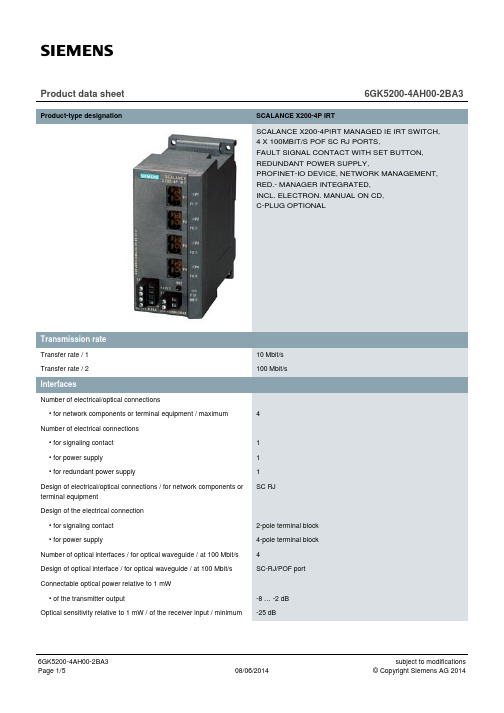
Product data sheet6GK5200-4AH00-2BA3 Product-type designation SCALANCE X200-4P IRTSCALANCE X200-4PIRT MANAGED IE IRT SWITCH,4 X 100MBIT/S POF SC RJ PORTS,FAULT SIGNAL CONTACT WITH SET BUTTON,REDUNDANT POWER SUPPLY,PROFINET-IO DEVICE, NETWORK MANAGEMENT,RED.- MANAGER INTEGRATED,INCL. ELECTRON. MANUAL ON CD,C-PLUG OPTIONALTransfer rate / 110 Mbit/sTransfer rate / 2100 Mbit/sNumber of electrical/optical connections• for network components or terminal equipment / maximum4Number of electrical connections• for signaling contact1• for power supply1• for redundant power supply1Design of electrical/optical connections / for network components orSC RJterminal equipmentDesign of the electrical connection• for signaling contact2-pole terminal block• for power supply4-pole terminal blockNumber of optical interfaces / for optical waveguide / at 100 Mbit/s4Design of optical interface / for optical waveguide / at 100 Mbit/s SC-RJ/POF portConnectable optical power relative to 1 mW• of the transmitter output-8 … -2 dBOptical sensitivity relative to 1 mW / of the receiver input / minimum-25 dBAttenuation / of fiber-optic cable transmission link / minimum0 dBnecessaryRange / at the optical interface / depending on the optical fiber used0 … 0.05 kmdesign of the removable storage / C-PLUG YesOperating voltage / of signaling contacts / at DC / rated value24 VOperating current / of signaling contacts / at DC / maximum0.1 AType of / supply voltage DCSupply voltage / external24 V• minimum18 V• maximum32 VProduct component / fusing at power supply input YesType of fusing / at input for supply voltage1,1 A / 33 VConsumed current / maximum0.4 AActive power loss / at 24 V / for DC9.6 WAmbient temperature• during operating-25 … +40 °C• during storage-40 … +70 °C• during transport-40 … +70 °CRelative humidity / at 25 °C / without condensation / during operating95 %/ maximumProtection class IP IP30Design compactWidth60 mmHeight125 mmDepth124 mmNet weight0.78 kgMounting type• 35 mm DIN rail mounting Yes• wall mounting Yes• S7-300 rail mounting Yes50Cascading in the case of a redundant ring / at reconfiguration time of<\~0.3\~sCascading in cases of star structuring Any (depending only on signal propagation time) Product function• CLI Yes• web-based management Yes • MIB support Yes • TRAPs via email Yes • Configuration with STEP 7Yes • Port mirroring No • for IRT / PROFINET IO switch Yes • PROFINET IO diagnosis Yes • switch-managed Yes Protocol / is supported• Telnet Yes • HTTP Yes • HTTPS Yes • TFTP Yes • FTP Yes • BOOTP No • SNMP v1Yes • SNMP v2Yes • SNMP v3Yes • DCP Yes • LLDP Yes Identification & maintenance function• I&M0 - device-specific information Yes • I&M1 – higher level designation/location designation YesProduct function• Port diagnostics Yes • Statistics Packet Size Yes • Statistics packet type Yes • Error statistics YesProduct function / DHCP client YesProduct function• Ring redundancy Yes • Redundancy manager Yes • Standby redundancy Yes • High Speed Redundancy Protocol (HRP)Yes • Media Redundancy Protocol (MRP)Yes • Parallel Redundancy Protocol (PRP)No• Passive listening YesProtocol / is supported / PRP YesProtocol / is supported / SSH YesProduct function / SICLOCK support YesProtocol / is supported• NTP No• SNTP YesStandard• for EMC / from FM FM3611: Class 1, Division 2, Group A, B, C, D / T4, CL.1, Zone 2,GP. IIC, T4• for hazardous zone EN 60079-0 : 2006, EN 60079-15: 2005, II 3 G Ex nA II T4 KEMA 07ATEX 0145X• for safety / of CSA and UL UL 60950-1, CSA C22.2 No. 60950-1• for hazardous area / of CSA and UL ANSI / ISA 12.12.01, CSA C22.2 No. 213-M1987, CL. 1 / Div. 2 /GP. A, B, C, D T4, CL. 1 / Zone 2 / GP. IIC, T4• for emitted interference EN 61000-6-4:2001• for interference immunity EN 61000-6-2:2001Verification of suitability EN 61000-6-2:2001, EN 61000-6-4:2001• CE mark Yes• C-Tick Yes• KC approval Yes• Railway application in accordance with EN 50155No• Railway application in accordance with EN 50124-1NoMarine classification association• American Bureau of Shipping Europe Ltd. (ABS)No• Bureau Veritas (BV)No• Det Norske Veritas (DNV)No• Germanische Lloyd (GL)No• Lloyds Register of Shipping (LRS)No• Nippon Kaiji Kyokai (NK)No• Polski Rejestr Statkow (PRS)NoInternet-Link• to website: Industry Mall /industrial-controls/mall• to website: Industrial communication /simatic-net• to website: Information and Download Center /automation/net/catalog• to website: Image database /bilddb• to website: CAx Download Manager /cax• to website: Industry Online Support letzte Änderung:Aug 6, 2014。
松下PLC编程手册(中文版)

1 - 11.1 继电器、存储器和常数表1.1.1 FP0/FP-e编号方式项目FP0-C10/C14/C16 FP-eFP0- C32FP0- T32C功能外部输入继电器(X)208点(X0~X12F) 根据外部输入通断。
外部输出继电器(Y)208点(Y0~Y12F) 外部输出通断。
内部继电器(R) (*注释2) 1008点 (R0~R62F) 只在程序内部通断的继电器。
定时器(T) (*注释2) 如果TM 指令定时到时,则相同编号的触点接通。
计数器(C) (*注释2)144点(T0~T99/C100~C143) (*注释1)如果CT 指令计数到,则相同编号的触点接通。
继电器特殊内部继电器(R)64点(R9000~R903F) 为根据规格条件通断的继电器,并用于标志。
外部输入继电器(WX)13字(WX0~WX12) 以1个字(16位)的数据指定16个外部输入点。
外部输出继电器(WY)13字(WY0~WY12) 以1个字(16位)的数据指定16个外部输出点。
内部继电器(WR) (*注释2)63字(WR0~WR62) 以1个字(16位)的数据指定16个内部继电器点。
数据寄存器(DT) (*注释2) 1660字(DT0~DT1659)6144字 (DT0~ DT6143)16384字 (DT0~ DT16383)被用于程序的数据存储区。
数据被处理为16位(1个字)。
定时器/计数器 设定值区(SV) (*注释2)144字(SV0~SV143)用于存储定时器的设定值以及计数器的缺省值。
以定时器/计数器数字进行存储。
定时器/计数器经过值区(EV) (*注释2)144字(EV0~EV143)用于存储通过定时器/计数器操作的经过值。
以定时器/计数器数字进行存储。
特殊数据寄存器(DT)112字(DT9000~ DT9111)112字(DT90000~DT90111)用于存储特殊数据的数据存储区。
不同的设置和错误代码将被存储。
PLC200系列 棒材打包机说明书

DKJ03全自动棒材打捆机使用说明书中华人民共和国北京航空航天大学目录一、机器的用途----------------------------------------------------------------1二、规格及性能----------------------------------------------------------------1三、工作原理及结构特点----------------------------------------------------1四、设备安装调试及试运转-------------------------------------------------4五、打捆机打捆工艺过程----------------------------------------------------8六、操作规程-------------------------------------------------------------------8七、电气原理------------------------------------------------------------------11八、设备的维护和安全技术------------------------------------------------12九、棒材打捆机地基说明---------------------------------------------------14十、易损件目录---------------------------------------------------------------15附图一、机器的用途在现代化钢材生产中,钢材的存储及运输也是一个重要的环节。
而钢材的捆扎成型是存储和运输所必须的,所以打捆机就成了钢铁企业精整包装的关键设备,而该机器就是用于不同规格的螺纹钢、圆钢等钢材捆扎成型的专用设备。
(完整版)四节运输带西门子200控制毕业设计

河南工业职业技术学院Henan Polytechnic Institute毕业设计(论文)题目:四节运输带的PLC控制班级:电气1201姓名:杨帅兵指导教师:韩金玲毕业设计任务书一、设计题目:四节运输带的PLC控制二、控制要求有一运输系统由四节运输带顺序相连而成,分别用电动机M1、M2、M3、M4拖动,控制要求有以下几点:1.起动时为了避免在前段运输皮带上造成物料堆积,要求逆物料流动方向按一定时间间隔顺序起动。
其起动顺序为:按下起动按钮后,M4先起动,经过10S,M3起动……最后M1起动。
2.停止时为了使运输皮带上不残留物料,要求顺物料流动方向按一定时间间隔顺序停止。
其停止顺序为:按下停止按钮时,M1先停止,经过10S,M2停止……最后M4停止。
3.当某运输带电机过载时,该运输带及前面的运输带立即停止,而后面的运输带电机待运完料才停止。
例如,M2电机过载,M1、M2立即停止,经过10S,M3停止,再经过10S,M4停止。
三、设计任务1.画出皮带运输机的主电路。
2.画出PLC的I/O接线图。
3.画出梯形图。
4.说明工作原理。
5.编写30000字左右的设计说明书。
四节运输带的PLC控制摘要PLC(可编程控制器)作为一种工业控制微型计算机,它以其操作方便、编程简单,尤其是它的高可靠性等优点,在工业生产过程中得到广泛应用。
它是应用大规模集成电路,以微处理器为核心,集微电子技术,自动化技术计算机技术,通信技术为一体,以工业自动化控制为目的的新型控制装置。
随着社会的不断发展,科学的不断进步,自动化程度也越来越高,传送带则理所当然的成为了自动化流水线运用上的宠儿,传送带设备的不断改进,不断发展,为自动化技术高速发展的今天,在自动化生产线的运输做出了不可磨灭的贡献。
本课题是用PLC控制四节传送带。
用PLC控制传送带具有程序设计简单、易于操作和理解、能够实现多种功能等优点。
此系统主要能够实现逆次启动和顺次停止,紧急故障处理等功能。
IPC 200 频率电压控制装置 技术及使用说明书

IPC200频率电压控制装置技术及使用说明书(Ver.2.0)南京爱浦克施电气有限公司二零一四年六月目录1概述 (1)1.1应用范围 (1)1.2主要特点 (1)1.3装置的主要功能 (2)2技术参数 (3)2.1机械及环境参数 (3)2.2额定电气参数 (3)2.3过载能力及功耗 (3)2.4主要技术指标 (3)3装置工作原理 (5)3.1电压(U)、频率(f)的测量方法 (5)3.2两段母线电压频率的切换方法 (6)3.3启动元件 (6)3.4低频动作原理 (7)3.5低压动作原理 (10)4硬件原理说明 (12)4.1硬件基本构成 (12)4.2各插件原理说明 (15)5定值内容及整定说明 (17)5.1装置参数及整定说明 (17)5.2保护定值及整定说明 (17)5.3出口组态定值及整定说明 (19)6软件结构及操作说明 (21)6.1软件结构 (21)6.2面板操作 (22)7装置可靠性说明 (24)附录1装置调试大纲 (26)附1.1出厂调试项目 (26)附1.2现场安装调试及试验项目 (26)附1.3装置的试运行与正式投运 (27)附录2装置运行与维护注意事项 (28)附2.1正常运行中的巡视和检查 (28)附2.2母线操作时的注意事项 (28)附2.3电网发生事故时,应及时检查装置动作情况 (28)附2.4装置出现异常告警时的检查 (28)附2.5关于定值修改需要注意的问题 (28)附2.6装置的定期试验检查 (29)附2.7线路操作时的注意事项 (29)附2.8旁路操作时的注意事项 (29)附2.9稳定控制装置检验规定 (29)附录3订货须知 (32)特别说明 (33)IPC200频率电压控制装置技术及使用说明书1概述根据电力系统对安全自动装置的需求,我公司成功地吸收原有的UFV系列装置的技术精华,开发出IPC200频率电压控制装置。
提供频率电压稳定控制功能。
1.1应用范围IPC200频率电压控制装置用于频率电压稳定控制,具有低频判断、低压判断、过频判断、过压判断等功能。
台达PLC各系列的功能说明
台达PLC各系列的功能说明
Delta PLC (Programmable Logic Controller)是由台达电子股份有限公司生产的PLC系统。
它采用强大的微处理器,配合先进的编程,具有智能化、用于控制各种工艺机械的自动化功能,广泛应用于工业自动化领域。
Delta PLC 包括多种系列,其中常见的有基于DSP(Digital Signal Processor)技术的DVP-PLC系列,型号涵盖DVP-ES2 、 DVP-EX2和DVP-EX。
这三种系列都具有强大的计算能力,可满足不同的控制要求,适用于各种应用领域。
DVP-ES2系列PLC具有先进的处理和控制能力,6路输入/8路输出的标准模块,可扩展至24路输入/16路输出,最高支持达到64路输入/64路输出,具有多种继电器输出和脉冲输出型号,最高支持多达16个继电器输出,可满足不同应用领域的控制需求。
另外,它还支持多种模拟量
I/O,从1路4mA~20mA输入,1路4mA~20mA输出,最高支持4路0~10V
输入,4路0~10V输出,可满足各种模拟量控制需求。
DVP-EX2系列PLC具有高性能的处理能力,可满足多媒体的各种控制需求,支持多种类型的输入和输出,可实现精细的控制,支持数字、模拟量、编码器和各种传感器,最高可支持128个数字输入/输出点,64个模拟量输入/输出点,128个编码器输入/输出点。
S7-200smart PLC模拟量输入模块使用说明

S7-200smart PLC模拟量输入模块使用说明当我们在实际的应用中需要对当前的温度或是压力进行采集显示的时候,我们需要用到模拟量模块来对模拟量信号进行采集,在这里我们以S7-200smart PLC的EMAE04模拟输入模块为例来说明如何使用这个模块来采集温度或是压力。
例如:现需要实时监控发电机机组的温度,假设变送器输出的信号为0到10V的电压信号,最大温度值为150。
最小温度值为0度。
要完成正确读取实际的温度值,需要进行以下三步操作:第一、正确的接线第二、正确的硬件组态第三、编写正确的程序1、按照变送器提供的信号输出接线方式进行正确的接线,对于EMAE04模块的信号接入如图所示:若变送器为三线制输出的变送器,则接线时,先把变送器的24V电源接上,变送器上的信号输出接端0+,0-端子接24V电源负。
2、打开S7-200smart的编程软件,打开其系统块对其进行硬件组态。
如图所示:注意:对于信号类型的选择,通道0的设置对通道1的设置也有效,通道2的设置对通道3 也同样有效。
3、编写转换程序S7-200smartPLC来说其最大的数字量为27648。
我们可以根据其得到的数字量的大小转换成我们实际的温度值。
对其转换程序,我们可以使用S7-200中的scaling模拟量转换库,使用库移植的方法把其移植到S7-200smart的软件中。
其移植方法可以参考前面所介绍的内容。
Input :表示需要转换的数字量,即采样所的数字量Ish:换算对象的高限,即最大模拟量所对应的数字量值(27648)Isl: 换算对象的低限,即最小模拟量所对应的数字量值(0)Osh:换算结果的高限,即测量范围最大值Osl:换算结果的底限,即测量范围最小值。
VD100:换算结果所存储的值。
第二部分:如何引用模拟量的地址在软件中,就可以看到,以上模块量模块的地址就是:AIW16 18 20 22AIW32 34 36 38。
四信F-MPM200多功能电力仪表使用说明书

F-MPM200多功能电力仪表使用说明书文档版本密级V1.1.2产品名称:F-MPM200共51页F-MPM200多功能电力仪表使用说明书此说明书适用于下列型号产品:型号产品类别Add:厦门市集美区软件园三期诚毅大街370号A06栋11层客户热线:400-8838-199电话:+86-592-6300320传真:+86-592-5912735网址文档修订记录日期版本说明作者2020-05-12V1.0.0初始版本HXF 2020-06-05V1.1.0更新版本陈佩云2020-08-10V1.1.1更新通讯协议陈佩云2020-08-11V1.1.2更新标题陈佩云著作权声明本文档所载的所有材料或内容受版权法的保护,所有版权由厦门四信通信科技有限公司拥有,但注明引用其他方的内容除外。
未经四信公司书面许可,任何人不得将本文档上的任何内容以任何方式进行复制、经销、翻印、连接、传送等任何商业目的的使用,但对于非商业目的的、个人使用的下载或打印(条件是不得修改,且须保留该材料中的版权说明或其他所有权的说明)除外。
商标声明Four-Faith、四信、、、均系厦门四信通信科技有限公司注册商标,未经事先书面许可,任何人不得以任何方式使用四信名称及四信的商标、标记。
注:不同型号配件和接口可能存在差异,具体以实物为准。
安全和注意事项危险和警告!本设备只能由专业人士进行安装。
对于因不遵守本手册中的说明而引起的故障,厂家将不承担任何责任。
触电、燃烧或爆炸的危险●设备只能由取得资格的工作人员才能进行安装和维护。
●对设备进行任何操作前,应隔离电压输入和电源供应,并且短路所有电流互感器的二次绕组。
●要用一个合适的电压检测设备来确认电压已切断。
●在将设备通电前,应将所有的机械部件,门和盖子恢复复位。
●设备在使用中应提供带正确的额定电压。
不采取这些预防措施可能造成设备损坏或人员受伤。
目录第一章产品简介 (3)1.1产品概述 (3)1.2产品特点 (3)1.3工作原理 (4)第二章技术指标 (5)2.1测量与计量功能 (5)2.2工作电压输入与功耗 (6)2.3物理特性 (6)2.4环境要求 (6)2.5蜂窝网络(选配) (6)2.6扩展模块 (7)2.7全显图 (7)2.8控制与事件 (8)第三章功能描述 (8)3.1测量参数 (8)3.1.1电压 (8)3.1.2电流 (9)3.1.3有功功率 (9)3.1.4无功功率 (9)3.1.5视在功率 (9)3.1.6功率因素 (9)3.1.7频率 (10)3.1.8需量统计 (10)3.2电能质量 (11)3.2.1概述 (11)3.2.2谐波总畸变率 (11)3.2.3谐波电压含有率 (12)3.2.4谐波电流含有率 (12)3.2.5电压波峰系数 (12)3.2.6电流K系数 (12)3.2.7谐波电压有效值 (12)3.2.8谐波电流有效值 (12)3.2.9谐波总有功功率有效值 (13)3.2.10谐波电能 (13)3.2.11频率偏差 (13)3.2.12电压偏差 (13)3.2.13电压不平衡率 (13)3.3电能及复费率统计 (14)3.3.1概述 (14)3.3.2有功电能 (14)3.3.3无功电能 (14)3.3.4复费率电能 (14)3.3.5历史电能 (15)3.4记录 (15)3.4.1概述 (15)3.4.2SOE事件记录 (16)3.4.3频率偏差记录 (16)3.4.4电压偏差记录 (16)3.4.6需量最值记录 (17)3.4.7实时量最值记录 (17)3.5定值系统 (17)3.5.1概述 (17)3.5.2定值分析 (17)3.5.2.1定值判断类型 (17)3.5.2.2定值对象类型 (17)3.5.2.3定值动作条件 (18)3.5.2.4定值动作时间 (18)3.5.2.5告警输出 (18)3.5.2.6举例 (18)第四章显示操作 (18)4.1显示概述 (18)4.2按键功能 (19)4.3数据查询 (19)4.3.1上电显示界面 (21)4.3.2电压类显示界面 (21)4.3.3电流类显示界面 (22)4.3.4频率类显示界面 (22)4.3.5功率类显示界面 (23)4.3.6电能类显示界面 (24)4.3.7电能质量类显示界面 (25)4.3.8需量类显示界面 (27)4.3.9模拟量输入类显示界面 (28)4.3.10设置类显示界面 (29)4.3.10.1仪表基本设置显示界面 (30)4.3.10.2通讯设置显示界面 (32)4.3.10.3清除设置显示界面 (33)4.3.10.4继电器设置显示界面 (34)4.3.10.5模拟量输出设置显示界面 (36)4.3.10.6偏差限值设置显示界面 (36)4.3.10.7错误记录显示界面 (37)4.3.10.8模拟量输入设置显示界面 (38)4.4就地编程 (38)4.4.1设置参数的查看 (38)4.4.2设置参数的修改 (38)第五章结构、安装与接口定义 (40)5.1装箱清单 (40)5.2安装与接线定义 (40)订购信息 (42)第一章产品简介1.1产品概述F-MPM200多功能电力仪表是针对电力系统、工矿企业、公用设施,电力智能监控等需求而设计的一款产品。
Menvier MF200和MF400传统产品范围控制面板概述说明书
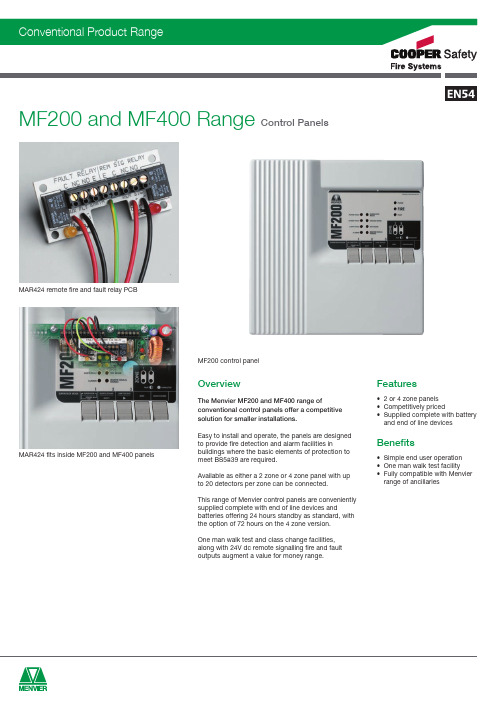
The Menvier MF200 and MF400 range of MAR424 fits inside MF200 and MF400 panels Features• 2 or 4 zone panelsMAR424 remote fire and fault relay PCBMF200 control panelDimensionsDWHH (mm)W (mm) D (mm)30030074CodeDescriptionMF200Conventional 2 zone control panel MF400Conventional 4 zone control panelMF400-72Conventional 4 zone control panel (72 hour standby)MAR424Conventional fire and fault relay PCB MFALOGFire alarm system log bookProduct CodesCode MF200MF400Description 2 zone control panel4 zone control panelStandards EN54 Pt2 & Pt4 1998, EN50130 Pt4 1996EN54 Pt2 & Pt4 1998, EN50130 Pt4 1996Specification Number of Zones 24Detectors per Zone 2020Number of Alarm Lines 22Alarm Circuit Load 375mA per circuit. 750mA total 375mA per circuit. 750mA total End of Line DevicesDetection circuits: 22K Ω resistor Detection circuits: 22K Ωresistor Alarm lines: 22K Ω resistorAlarm lines: 22K Ω resistor Auxiliary Fire Signal Output 24V dc pull to 0V . Max 10mA 24V dc pull to 0V . Max 10mA Auxiliary Fault Output 24V dc pull to 0V . Max 10mA24V dc pull to 0V . Max 10mAAuxiliary dc Output24V dc fused. 32mA24V dc fused. 32mA(up to 100mA at the expense of alarm load)(up to 100mA at the expense of alarm load)Mains Input Voltage 240V ac +10%-15%240V ac +10%-15%System Operating Voltage 24V dc 24V dcStandby Duration 24 hours24 hours (72 hours on MF400-72)Battery1 x 4Ah sealed lead acid battery1 x 4Ah sealed lead acid battery(1 x 7Ah on MF400-72)Recharge Period 48 hours (80% in 24 hours)48 hours (80% in 24 hours)Environmental Operating Temperature -5°C to +40°C -5°C to +40°C Humidity (Non Condensing)0 to 75% RH0 to 75% RHPhysical ConstructionABS/Polycarbonate housing. Steel back box.ABS/Polycarbonate housing. Steel back box.Dimensions (H x W x D)300mm x 300mm x 74mm300mm x 300mm x 74mm Weight4.8kg 4.8kg (6.0kg on MF400-72)Ingress Protection IP30IP30Cable entriesTop: 10 x 20mm conduit entriesTop: 10 x 20mm conduit entriesBottom: 1 x 20mm conduit entry (mains cable)Bottom: 1 x 20mm conduit entry (mains cable)Back: 1 x mains cable entry slotBack: 1 x mains cable entry slotTechnical SpecificationInstallation1.A full set of Installation and user Instructions issupplied with each panel to assist the installer to carry out the work efficiently and safely, and theuser to perform routine tests.2.Panels are wall mounted via keyhole slot mountingholes on back of housing.3.Mains power supply cable must be routed via thedesignated 20mm conduit entry on the top orbottom of the housing, or via the rear cable entry slot. The mains terminal block is provided with fuse protection.4.A total of 10 x 20mm conduit entries are providedon the top of the housing for zone, alarm andoutput cables. Blanking plugs are supplied for un-used entries.5. Standby battery connected via push-on terminalconnectors.6.End of line (EOL) devices are supplied with thepanel and must be fitted at the end of eachdetector and alarm circuit wiring.7.Front cover retained by anti-tamper screws. System Functionality1.Normal and supervisor mode facility. Supervisormode protected by 4 digit security code to prevent unauthorised use.2.Supervisor mode provides access to test mode,where zones can be tested individually.3.One man walk test feature permits each manualcallpoint and detector on the zone in test modeto be put into fire condition and activates thealarms for 2 seconds. Panel automatically resets the zone 10 seconds after each device has been tested. A fire condition received from a zone not in test mode results in an immediate alarm, overriding the test mode.4.Supervisor mode also provides facility todisable/isolate the following for maintenance orother purposes•each detection zone independently•the alarm circuits•the remote signal outputs User Interface1.Attractive compact panel with easy to use 5 buttonkeyboard to control all functionsprehensive power, fire and fault LED indicatorsand integral piezo buzzer for on-board fire or fault indicationInterface Options1.Class change input facility. Terminals provided forswitching of alarm circuits to indicateschool/college class change.2.24V dc outputs provided for remote signalling offire and fault conditions.3.Optional relay board available (MAR424) to convertfire and fault signals to volt free change over rated at 24V dc, 1A dc.4.Auxiliary 24V dc output power supply provided asstandard.Detection Capacity1.Up to 20 detectors per zone. End of line monitoringdevices must be fitted and are supplied asstandard.2.Detector circuits are monitored for open circuit,short circuit and detector removal.Alarm Capacity1.Two separate alarm lines, each with a maximumrated load of 375mA.2.Alarm lines are monitored for open circuit and shortcircuit faults.Cooper Lighting and Safety Ltd, Wheatley Hall Road, Doncaster, South Yorkshire, DN2 4NB. UK.T: +44 (0) 1302 303350 l F: +44 (0) 1302 303332 l E: techsupport@ l W: ZONE 1ZONE 4*ZONE 3*ZONE 2+ - E MDB800DETECTOR BASEMBG914/917CALLPOINT connect as per instuctions+ VE IN & OUT ON 1- VE IN & OUT ON 2END OF LINE 22KOhm RESISTORsubsequent zones END OF LINE 22KOhm RESISTOR+ - E + - E + - EALARM 2ALARM 1+ - E + - Esubsequent alarm linesREM SIGAUX FAULT+ - E + - EF A U L T S IG N A LI S O L A T I N G F I R E S I G N A LMAR724MAR42424V 10mAAUX DCCLASS CHANGE+ - E + - ES W I T C H /C O N T A C T O R /T I M E R (A P P L Y N O V O L T A G E )24V d c A U X I L A R Y S U P P O R T* MF400 ONLYAUX FAULT+ - EREMOTE SIGNAL+ - E+ - E+ -C NC NO E E C NC NOMAR424AUX FAULT REMOTE SIGNALRELAY OUTPUTS 24V 1A (resistive)24V 10mA COIL24V 10mA COILAUX FAULT /REMOTE SIGNAL+ - E24V dc 10mA PULL TO 0VDOOR RELEASE UNITS RELAY OUTPUTS 240V dc 10AAUX FAULT /REMOTE SIGNAL+ - EMAR724NC C NO NO C NC24V 10mA COIL+ -C = COMMONNC = NOT NORMALLY CONNECTED NO = NORMALLY OPENStandard Panel Connections。
CDMP200技术及使用手册
目 录1概述 (5)1.1应用范围 (5)1.2主要特点 (5)1.3保护功能 (6)1.4测量功能 (7)1.5监视功能 (8)1.6控制功能 (8)1.7事件记录 (9)1.8故障录波 (9)1.9人机接口 (9)1.10通信功能 (10)2技术参数 (11)2.1环境条件 (11)2.2工作电源 (11)2.3控制电源 (11)2.4交流电流回路 (11)2.5交流电压回路 (11)2.6开关量输入回路 (11)2.7继电器输出回路 (12)2.8测量精度 (12)2.9绝缘性能 (12)2.10电磁兼容性能 (12)2.11机械性能 (12)3保护原理 (13)3.1CT回路断线告警 (13)3.2PT回路断线告警 (14)3.3控制电源失电告警 (14)3.4合闸回路断线告警 (15)3.5跳闸回路断线告警 (15)3.6保护选项:电动机保护 (15)3.7保护选项:方向闭锁 (15)3.8保护选项:低压闭锁 (16)3.9电流速断保护 (16)3.10限时电流速断保护 (17)3.11定时限过流保护 (18)3.12反时限过流保护 (19)3.13后加速保护 (20)3.14过负荷保护 (21)3.15负序电流保护 (21)3.16零序电流保护 (22)3.17单相接地选线保护 (22)3.18过电压保护 (23)3.19低电压保护 (24)3.20失压保护 (24)3.21负序电压保护 (25)3.22零序电压保护 (25)3.23复合电压过流保护 (26)3.24低周减载保护 (27)3.25低压解列保护 (28)3.26重合闸保护 (28)3.27备自投保护 (29)3.28过热保护 (30)3.29逆功率保护 (31)3.30启动时间过长保护 (31)3.31定时限Ix过流保护 (32)3.32反时限Ix过流保护 (32)3.33自定义保护 (33)4整定说明 (34)4.1保护功能设置整定表 (34)4.2保护定值整定表 (35)4.3保护投退整定表 (37)4.4设备参数整定表 (38)4.5脉冲电度参数整定表 (39)4.6电度底码设置整定表 (39)4.7开关量参数整定表 (39)5梯形图编程 (40)5.1编程环境简介 (40)5.2菜单说明 (40)5.3符号说明 (41)5.4CDMP200梯形图编程对照表 (44)5.4.1输入量 (44)5.4.2输出量 (47)6安装与接线 (49)6.1安装 (49)6.1.1环境条件 (49)6.1.2屏柜要求 (49)6.2接线 (49)6.2.1工作电源 (49)6.2.2相电压输入 (50)6.2.3零序电压输入 (50)6.2.4相电流输入 (50)6.2.5零序电流输入 (50)6.2.6辅助电流输入 (51)6.2.7辅助电压输入 (51)6.2.8开关量输入 (51)6.2.9继电器输出 (51)6.2.10断路器操作接口 (51)7基本操作与使用 (53)7.1装置上电 (53)7.1.1主机模块初始化 (53)7.1.2面板模块初始化 (53)7.2面板操作 (53)7.2.1面板功能 (53)7.2.2液晶显示屏 (54)7.2.3断路器分位/合位指示灯 (54)7.2.4故障/告警信号指示灯 (54)7.2.5信号复归按键 (54)7.2.6调试端口 (55)7.2.7高亮度LED发光指示灯 (55)7.2.8液晶显示屏操作按键 (55)7.2.9断路器分闸/合闸操作按键 (55)7.2.10遥控/本地指示灯 (56)7.2.11遥控/本地锁 (56)7.3菜单操作 (56)7.3.1一次测量数据 (56)7.3.2二次测量数据 (56)7.3.3电度量数据 (57)7.3.4开关量状态 (57)7.3.5实时波形 (57)7.3.6事件记录 (58)7.3.7故障录波 (58)7.3.8保护定值 (59)7.3.9调试信息 (60)7.3.10自检信息 (60)7.3.11参数查看 (60)7.3.12参数设置 (63)7.3.13多套定值查看 (64)7.3.14多套定值设置 (65)8调试大纲 (66)8.1通电前检查 (66)8.2通电检查 (66)8.3投运前检查 (67)8.4投运后注意事项 (67)8.5运行维护注意事项 (67)9附录 (68)9.1CDMP200机械尺寸图及开孔图 (68)9.2CDMP200背面端子图 (69)9.3CDMP200典型接线图(线路保护) (70)9.4CDMP200典型接线图(变压器保护) (71)9.5CDMP200典型接线图(高压电动机保护) (72)9.6CDMP200典型接线图(高压电容器保护) (73)9.7CDMP200典型接线图(发电机后备保护) (74)9.8CDMP200典型接线图(变压器后备保护) (75)9.9CDMP200典型接线图(进线备自投) (76)9.10CDMP200典型接线图(母分备自投) (77)1概述CDMP200通用型保护测控装置(以下简称CDMP200)是集保护、测量、监视、控制、人机接口、通信等多种功能于一体,同时溶入了先进的软件二次设计思想,真正意义上实现在线可编程功能(包括保护可编程和控制可编程)的数字式多功能继电器。
斯芬斯斯电子SIMATIC ET 200SP 4路2线电压输入模块说明书
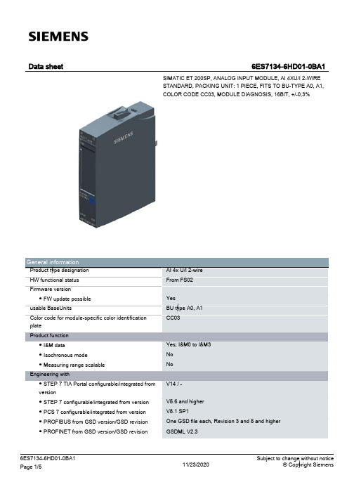
24 V 19.2 V 28.8 V Yes
Input current Current consumption, max.
37 mA; without sensor supply
Encoder supply 24 V encoder supply ● 24 V ● Short-circuit protection ● Output current, max.
integrating (Sigma-Delta)
16 bit Yes 16.6 / 50 / 60 Hz 180 / 60 / 50 ms
4; None; 4/8/16 times Yes
Encoder Connection of signal encoders ● for voltage measurement ● for current measurement as 2-wire transducer — Burden of 2-wire transmitter, max. ● for current measurement as 4-wire transducer
● -10 V to +10 V — Input resistance (-10 V to +10 V)
● -5 V to +5 V — Input resistance (-5 V to +5 V)
Input ranges (rated values), currents ● 0 to 20 mA — Input resistance (0 to 20 mA) ● 4 mA to 20 mA — Input resistance (4 mA to 20 mA)
● Group error ● Overflow/underflow Diagnostics indication LED ● Monitoring of the supply voltage (PWR-LED) ● Channel status display ● for channel diagnostics ● for module diagnostics
VAMP200系列
另外,VAMP 的保护继电器结合了基于快速傅立叶变换的电能质量评估和基于故障阻 抗计算的故障定位。
用户特殊的配置可通过 VAMPSET 软件编程获得。
系统故障后,保护通过事件顺序记录,故障值记录和故障录波的能力来提供随后的故 障分析。
TCP/IP, RS 485 或光纤
*) 详细内容请教你的用户
5
VAMP 馈线 / 电动机保护系列
VAMPSET 整定和配置工具
VAMPSET 是用户界面友好,免费的装置管理软件,用来整定,设置参数和配置 VAMP 继电器。
通过 VAMPSET 软件,装置的参数,配置和记录数据能在操作员的 PC 和 VAMP 装置间 交换。
电压下降和膨胀
扰动记录 温度 IEC 60870-5-103 Modbus TCP Modbus RTU
Profibus DP SPA-bus 通讯 DNP 3.0 人机通讯,显示
人机通讯,PC 移植通道到 IEC61850 相电流 CT 的数量 零序电流 CT 的数量 电压输入 VT 的数量 数字量输入的数量
8可编程段3i三相电流i0零序电流i2电流不平衡il平均和最小需求电流3u相电压线电压u0零序电压u2电压不平衡xfault短路故障阻抗故障定位xfault接地故障阻抗补偿电网有功电能输出输入eqeq无功电能输出输入pf功率因数电流的2nd到15th谐波和thd电压的2nd到15th谐波和thdcb磨损的条件监视ct的条件监视vt的条件监视iec608705103modbustcpmodbusrtupro?busdpspabus通讯dnp30相电流ct的数量零序电流ct的数量电压输入vt的数量1881218用di19di20选项额外的数字量输入数量1218告警输出数量可选的ma输出的数量rtd输入416416416416vamp馈线电动机保护系列电弧光保护无论是使用时间级差或基于保护配置闭锁原理传统的保护系统不能提供变电站故障足够快的保护
S7-200概述
CPU224的主机共有14个输入点(I0.0~I0.7、I1.0~I1.5)和10个输出点(Q0.0~ Q0.7,Q1.0~Q1.1),在编写端子代码时采用八进制,没有0.8和0.9。CPU224输 入电路参见图2-2,它采用了双向光电耦合器,24V 直流极性可任意选择,系统 设置1M 为输入端子(I0.0~I0.7)的公共端,2M 为(I1.0~I1.5)输入端子的 公共端。
(5)中断输入允许以极快的速度对过程信号的上升沿作出响应。
(6)EEPROM 存储器模块(选件)
可作为修改与拷贝程序的快速工具,无需编程器并可进行辅助软件归档工作。
(7)电池模块
用户数据(如标志位状态、数据块、定时器、计数器)可通过内部的超级电容存储大约5天。选用电池 模块能延长存储时间到200天(10年寿命)。电池模块插在存储器模块的卡槽中。
2.3 扩展功能模块
2.3.1 扩展单元及电源模块
1. 扩展单元
扩展单元没有 CPU,作为基本单元输入/输出点数的扩充,只能与基本单元连接 使用。不能单独使用。S7-200的扩展单元包括数字量扩展单元,模拟量扩展单元, 热电偶、热电阻扩展模块,PROFIBUS-DP 通信模块。
用户选用具有不同功能的扩展模块,可以满足不同的控制需要,节约投资费用。连接时 CPU 模块放在 最左侧,扩展模块用扁平电缆与左侧的模块相连。
2.2.3 PLC 的 CPU 的工作方式
1. CPU 的工作方式 CPU 前面板上用两个发光二极管显示当前工作方式,绿色指示灯亮,表示为运行 状态,红色指示灯亮,表示为停止状态,在标有 SF 指示灯亮时表示系统故障, PLC 停止工作。 (1)STOP(停止)。CPU 在停止工作方式时,不执行程序,此时可以通过编程装 置向 PLC 装载程序或进行系统设置,在程序编辑、上下载等处理过程中,必须把 CPU 置于 STOP 方式。 (2)RUN(运行)。CPU 在 RUN 工作方式下,PLC 按照自己的工作方式运行用户程 序。
- 1、下载文档前请自行甄别文档内容的完整性,平台不提供额外的编辑、内容补充、找答案等附加服务。
- 2、"仅部分预览"的文档,不可在线预览部分如存在完整性等问题,可反馈申请退款(可完整预览的文档不适用该条件!)。
- 3、如文档侵犯您的权益,请联系客服反馈,我们会尽快为您处理(人工客服工作时间:9:00-18:30)。
Cleanliness
These devices should be handled in a clean environment. Do not attempt to clean die after installation.
ESD These devices very susceptible to ESD and are rated Class 0 (0-199V) per HBM MIL-STD-883, method 3015.7 [C = 100pF ±10%, R = 1.5kΩ ±1%]. Even though tested die pass 100V ESD, they must be handled in a static-free environment. General Handling The protective polymer coating on the active areas of these devices provides scratch protection, particularly for the metal airbridge that contacts the anode. Die can be handled with tweezers or vacuum pickups and are suitable for use with automatic pick-and-place equipment.
Electrical Specifications @ +25°C
Symbol CT CT RS RS VF VR IR RθJL TL
1. 2. 3. 4.
Parameter Total Capacitance Total Capacitance Series Resistance Series Resistance Forward Voltage Reverse Voltage Reverse Current Thermal Resistance Lifetime
Typical Performance Curves @ +25°C1
Typical Total Resistance RS vs. Forward Current and Frequency
5 4
0.025 0V 0.020
Typical Total Capacitance CP vs. Reverse Voltage and Frequency
1. 2. 3.
Dimensions are in inches, () are in mm. Unless otherwise noted, tolerance are inches + .001” (millimeters + .025 mm). Schematic is for junction side up.
1
元器件交易网
Silicon Flip Chip PIN Diode Handling Procedures
The following precautions should be observed to avoid damaging these devices.
MA4FCP200 Mounting Techniques
Total capacitance is equivalent to the sum of junction capacitance C j and parasitic capacitance. Series resistance RS is equivalent to the total diode series resistance including the junction resistance Rj. RS and CP measures on an HP4291A with die mounted in an ODS-186 package with conductive silver epoxy. Steady-state R θJL measured with die mounted in an ODS-186 package with conductive silver epoxy.
元器件交易网
MA4FCP200
Silicon Flip Chip PIN Diode
Features
• • • • • • • • Low Series Resistance Low Capacitance High Cut-off Frequency Silicon Nitride Passivation Polyimide Scratch Protection Designed for Automated Pick and Place Insertion Rugged by Design Surface Mountable
Solder Die Attach Solder that does not scavenge gold, such as Indalloy #2, is recommended. Sn-Pb based solders are not recommended due to solder embrittlement. Do not expose die to a temperature greater than 235°C, or greater than 200°C for longer than 10 seconds. No more than three seconds of scrubbing should be required for attachment. Epoxy Die Attach Assembly can be preheated to 125 to 150°C. Use a minimum amount of silver epoxy. Cure epoxy as per manufacturer’s schedule. For extended cure times, temperatures should be kept below 200°C.
Absolute Maximum Ratings1
Parameter Forward Current2 Reverse Voltage Operating Temperature Storage Temperature Dissipated Power2 Mounting Temperature Absolute Maximum 125 mA -70 V -55°C to +150°C -55°C to +150°C 145 mW +235°C for 10 seconds
1. Exceeding these limits may cause permanent damage. 2. Steady-state R θJL measured with die mounted in an ODS-186 package with conductive silver epoxy..
These devices were designed for insertion onto hard or soft substrates with the junction side down. They can be mounted with conductive epoxy or with a low temperature solder preform. The die can also be assembled with the junction side up, and wire or ribbon bonds made to the pads.
Applications
These devices are well suited as series diodes in broadband multi-throw switches through 26 GHz. In addition, the exceptional RC product makes them useful as shunt switches at millimeter frequencies. The low parasitic values of L and C make additional circuit tuning unnecessary.
Case Style ODS-12641, 2, 3
B G E
A C D
Description
M/A-COM’s MA4FCP200 series is a silicon flip chip PIN diode fabricated with M/A-COM’s patented HMIC™ process. This diode is fabricated on epitaxial wafers using a process designed for repeatable electrical characteristics and extremely low parasitics. This diode is fully passivated with Silicon Nitride and has an additional layer of Polyimide for scratch protection. These protective coatings prevent damage to the junction during automated or manual handling. This flip chip configuration is suitable for pick and place insertion.
Test Conditions -10 Volts, 1 MHz -10 Volts, 1 GHz 50 mA, 100 MHz 50 mA, 1 GHz 2, 3 100 mA 10 µA -70 V
