technote483 Accessing UI Context and Non UI Context Object Instances
android测试题及答案

android测试题及答案1. Android系统中,Activity的生命周期包含哪些状态?- A. onCreate(), onStart(), onResume(), onPause(), onStop(), onDestroy()- B. onCreate(), onStart(), onResume(), onPause(), onStop(), onDestroy(), onRestart()- C. onCreate(), onStart(), onResume(), onPause(), onStop(), onRestart(), onDestroy()- D. onCreate(), onRestart(), onStart(), onResume(), onPause(), onStop(), onDestroy()答案:C2. 在Android开发中,如何实现Activity之间的数据传递?- A. 使用Intent对象- B. 使用SharedPreferences- C. 使用数据库- D. 使用文件存储答案:A3. Android中,Service和Activity有什么区别?- A. Service没有用户界面,而Activity有- B. Activity没有用户界面,而Service有- C. Service和Activity都没有用户界面- D. Service和Activity都有用户界面答案:A4. Android中,如何实现屏幕旋转时Activity数据的保存和恢复? - A. 重写onSaveInstanceState()和onRestoreInstanceState()方法- B. 重写onPause()和onResume()方法- C. 重写onCreate()和onDestroy()方法- D. 重写onStart()和onStop()方法答案:A5. 在Android中,如何监听屏幕的亮灭状态?- A. 使用SensorManager监听光线传感器- B. 使用PowerManager监听电源状态- C. 使用BroadcastReceiver监听ACTION_SCREEN_OFF和ACTION_SCREEN_ON广播- D. 使用Handler定时检测电源状态答案:C6. Android中,如何实现应用的多语言支持?- A. 在res目录下创建不同语言的资源文件,并在代码中动态加载- B. 使用SharedPreferences存储用户选择的语言,并在代码中动态加载- C. 在代码中硬编码不同语言的字符串- D. 使用第三方库自动翻译应用内容答案:A7. 在Android开发中,如何实现应用的后台运行?- A. 使用Service- B. 使用BroadcastReceiver- C. 使用ContentProvider- D. 使用IntentService答案:A8. Android中,如何实现应用的权限请求?- A. 在AndroidManifest.xml中声明权限- B. 在代码中动态请求权限- C. 同时使用A和B- D. 无需请求权限答案:C9. Android中,如何实现应用的横竖屏切换?- A. 在AndroidManifest.xml中设置Activity的android:screenOrientation属性- B. 在代码中动态设置Activity的requestedOrientation属性 - C. 使用SensorManager监听屏幕旋转事件- D. 使用Handler定时检测屏幕旋转状态答案:A10. 在Android开发中,如何实现应用的内存优化?- A. 避免内存泄漏- B. 减少Bitmap的使用- C. 使用对象池- D. 以上都是答案:D结束语:以上是Android测试题及答案,希望对您的学习和工作有所帮助。
Qt笔试题集锦-单选48题+多选34题(带答案)
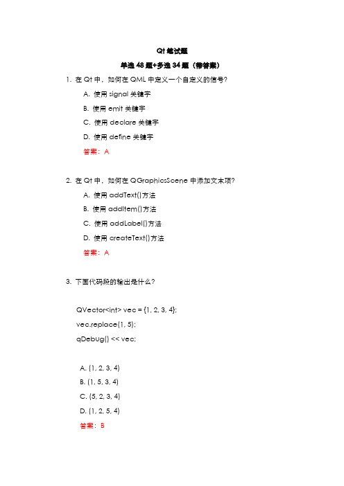
Qt笔试题单选48题+多选34题(带答案)1. 在Qt中,如何在QML中定义一个自定义的信号?A. 使用signal关键字B. 使用emit关键字C. 使用declare关键字D. 使用define关键字答案:A2. 在Qt中,如何在QGraphicsScene中添加文本项?A. 使用addText()方法B. 使用addItem()方法C. 使用addLabel()方法D. 使用createText()方法答案:A3. 下面代码段的输出是什么?QVector<int> vec = {1, 2, 3, 4};vec.replace(1, 5);qDebug() << vec;A. (1, 2, 3, 4)B. (1, 5, 3, 4)C. (5, 2, 3, 4)D. (1, 2, 5, 4)答案:B4. 在Qt中,如何确保QPainter对象支持在抗锯齿模式下进行绘图?A. QPainter::setAntialiasing(true)B. QPainter::AntialiasingC. QPainter::setRenderHint(QPainter::Antialiasing, true)D. QPainter::setSmoothRendering(true)答案:C5. 下面代码段的输出是什么?QHash<QString, int> hash;hash["one"] = 1;hash["two"] = 2;hash["three"] = 3;qDebug() << hash.size();A. 1B. 2C. 3D. 0答案:C6. 在Qt中,如何在一个QWidget上设置自定义绘图背景?A. 重写paintEvent()B. 重写drawEvent()C. 重写renderEvent()D. 重写backgroundEvent()答案:A7. 下面代码段的输出是什么?QList<int> list = {1, 2, 3, 4};list.removeOne(3);qDebug() << list;A. (1, 2, 3, 4)B. (1, 2, 4)C. (2, 3, 4)D. (1, 3, 4)答案:B8. 在Qt中,如何在QWidget中捕获并处理键盘事件?A. 重写keyPressEvent()B. 重写keyEvent()C. 重写keyboardEvent()D. 重写keyInputEvent()答案:A9. 下面代码段的输出是什么?QString str = "Hello, World!";qDebug() << str.section(',', 1, 1).trimmed();A. "Hello"B. " World!"C. "World"D. " World"答案:C10. 在Qt中,如何设置QMainWindow的中央小部件?A. setCentralWidget()B. addCentralWidget()C. setMainWidget()D. addMainWidget()答案:A11. 下面代码段的输出是什么?QSet<int> set = {1, 2, 3, 4};set.remove(2);qDebug() << set;A. {1, 2, 3, 4}B. {1, 3, 4}C. {2, 3, 4}D. {1, 2, 4}答案:B12. 在Qt中,QTimer对象的用途是什么?A. 提供线程管理B. 提供定时功能C. 提供信号槽连接D. 提供文件管理答案:B13. 下面代码段的输出是什么?QString str = "abcdef";qDebug() << str.contains("cd");A. trueB. falseC. 1D. 0答案:A14. 在Qt中,如何在QPushButton上设置图标?A. setIcon()B. addIcon()C. setButtonIcon()D. addButtonIcon()答案:A15. 下面代码段的输出是什么?QVector<int> vec = {10, 20, 30, 40};qDebug() << vec.first() << st();A. 10 40B. 10 30C. 20 40D. 20 30答案:A16. 在Qt中,如何在QGraphicsScene中添加一个图形项?A. addItem()B. addGraphic()C. appendItem()D. insertGraphic()答案:A17. 下面代码段的输出是什么?QMap<QString, int> map;map.insert("A", 1);map.insert("B", 2);map.insert("C", 3);qDebug() << map.value("B");A. 1B. 2C. 3D. 0答案:B18. 在Qt中,如何捕获QWidget的鼠标移动事件?A. 重写mouseMoveEvent()B. 重写mouseEvent()C. 重写mouseDragEvent()D. 重写mouseTrackEvent()答案:A19. 下面代码段的输出是什么?QList<int> list = {1, 2, 3, 4};list.append(5);qDebug() << list.size();A. 4B. 5C. 6D. 7答案:B20. 在Qt中,如何在QTableView中设置列宽?A. setColumnWidth()B. setColumnSize()C. setWidth()D. setColumnSpan()答案:A21. 下面代码段的输出是什么?QHash<int, QString> hash;hash[1] = "one";hash[2] = "two";hash[3] = "three";qDebug() << hash.contains(2);A. trueB. falseC. 1D. 0答案:A22. 在Qt中,如何在QGraphicsScene中添加一个文本项?A. addText()B. addLabel()C. addItem()D. addString()答案:A23. 下面代码段的输出是什么?QVector<int> vec = {1, 2, 3, 4};vec.clear();qDebug() << vec.isEmpty();A. trueB. falseC. 1D. 0答案:A24. 在Qt中,如何在QComboBox中添加一个选项?A. addItem()B. appendItem()C. insertItem()D. setItem()答案:A25. 下面代码段的输出是什么?QString str = "12345";qDebug() << str.at(2);A. "1"B. "2"C. "3"D. "4"答案:C26. 在Qt中,如何在QWidget中启用鼠标追踪?A. setMouseTracking(true)B. enableMouseTracking(true)C. setTracking(true)D. enableTracking(true)答案:A27. 下面代码段的输出是什么?QList<int> list = {1, 2, 3, 4};list.replace(2, 5);qDebug() << list;A. (1, 2, 3, 4)B. (1, 2, 5, 4)C. (1, 5, 3, 4)D. (5, 2, 3, 4)答案:B28. 在Qt中,如何在QWidget中捕获窗口关闭事件?A. 重写closeEvent()B. 重写destroyEvent()C. 重写exitEvent()D. 重写shutdownEvent()答案:A29. 下面代码段的输出是什么?QVector<int> vec = {1, 2, 3, 4};vec.replace(1, 5);qDebug() << vec;B. (1, 5, 3, 4)C. (5, 2, 3, 4)D. (1, 2, 5, 4)答案:B30. 下面代码段的输出是什么?QHash<QString, int> hash;hash["one"] = 1;hash["two"] = 2;hash["three"] = 3;qDebug() << hash.size();A. 1B. 2C. 3D. 0答案:C31. 下面代码段的输出是什么?QList<int> list = {1, 2, 3, 4};list.removeOne(3);qDebug() << list;A. (1, 2, 3, 4)C. (2, 3, 4)D. (1, 3, 4)答案:B32. 下面代码段的输出是什么?QString str = "Hello, World!";qDebug() << str.section(',', 1, 1).trimmed();A. "Hello"B. " World!"C. "World"D. " World"答案:C33. 下面代码段的输出是什么?QSet<int> set = {1, 2, 3, 4};set.remove(2);qDebug() << set;A. {1, 2, 3, 4}B. {1, 3, 4}C. {2, 3, 4}D. {1, 2, 4}答案:B34. 下面代码段的输出是什么?QString str = "abcdef";qDebug() << str.contains("cd");A. trueB. falseC. 1D. 0答案:A35. 下面代码段的输出是什么?QVector<int> vec = {10, 20, 30, 40};qDebug() << vec.first() << st();A. 10 40B. 10 30C. 20 40D. 20 30答案:A36. 下面代码段的输出是什么?QMap<QString, int> map;map.insert("A", 1);map.insert("B", 2);map.insert("C", 3);qDebug() << map.value("B");A. 1B. 2C. 3D. 0答案:B37. 下面代码段的输出是什么?QList<int> list = {1, 2, 3, 4};list.append(5);qDebug() << list.size();A. 4B. 5C. 6D. 7答案:B38. 下面代码段的输出是什么?QHash<int, QString> hash;hash[1] = "one";hash[2] = "two";hash[3] = "three";qDebug() << hash.contains(2);A. trueB. falseC. 1D. 0答案:A39. 下面代码段的输出是什么?QVector<int> vec = {1, 2, 3, 4};vec.clear();qDebug() << vec.isEmpty();A. trueB. falseC. 1D. 0答案:A40. 下面代码段的输出是什么?QString str = "12345";qDebug() << str.at(2);A. "1"B. "2"C. "3"D. "4"答案:C41. 下面代码段的输出是什么?QList<int> list = {1, 2, 3, 4};list.replace(2, 5);qDebug() << list;A. (1, 2, 3, 4)B. (1, 2, 5, 4)C. (1, 5, 3, 4)D. (5, 2, 3, 4)答案:B42. 下面代码段的输出是什么?QSet<int> set = {1, 2, 3, 4};qDebug() << set.size();A. 1B. 2C. 3D. 4答案:D43. 下面代码段的输出是什么?QMap<QString, int> map;map.insert("key1", 1);map.insert("key2", 2);map.insert("key3", 3);qDebug() << map.keys().contains("key2");A. trueB. falseC. 1D. 0答案:A44. 下面代码段的输出是什么?QString str = "Hello Qt!";qDebug() << str.indexOf("Qt");A. 1B. 0C. 6D. 5答案:C45. 下面代码段的输出是什么?QVector<int> vec = {1, 2, 3, 4, 5};vec.remove(1);qDebug() << vec;A. (1, 2, 3, 4, 5)B. (1, 3, 4, 5)C. (2, 3, 4, 5)D. (1, 3, 5)答案:B46. 下面代码段的输出是什么?QMap<int, QString> map;map.insert(1, "one");map.insert(2, "two");map.insert(3, "three");map.remove(2);qDebug() << map.size();A. 1B. 2C. 3D. 0答案:B47. 下面代码段的输出是什么?QString str = "OpenAI";qDebug() << str.left(4);A. "Open"B. "AI"C. "OpenAI"D. "penA"答案:A48. 下面代码段的输出是什么?QVector<int> vec = {1, 2, 3, 4};vec.swap(1, 3);qDebug() << vec;A. (1, 2, 3, 4)B. (1, 4, 3, 2)C. (4, 2, 3, 1)D. (1, 3, 2, 4)答案:B多选题1. 下面哪些类是QObject的直接子类?A. QWidgetB. QTimerC. QThreadD. QString答案:A, B, C2. 以下哪些关于信号和槽的描述是正确的?A. 信号和槽可以跨线程连接B. 槽函数必须是QObject的成员函数C. 自定义信号必须在signals关键字下声明D. 槽函数可以是普通函数答案:A, C, D3. 以下哪些类支持QPainter的绘图操作?A. QPixmapB. QImageC. QSvgRendererD. QPicture答案:A, B, D4. 以下哪些关于QEventLoop的描述是正确的?A. QEventLoop可以用于实现事件驱动的编程B. QEventLoop可以嵌套使用C. QEventLoop必须在主线程中运行D. QEventLoop可以手动停止答案:A, B, D5. 下面哪些类可以用于处理XML数据?A. QDomDocumentB. QXmlStreamReaderC. QXmlStreamWriterD. QJsonDocument答案:A, B, C6. 以下哪些是QVariant类支持的数据类型?A. intB. doubleC. QStringD. QVector答案:A, B, C7. 下面哪些类可以用于管理应用程序的配置设置?A. QSettingsB. QConfigC. QPreferencesD. QIniSettings答案:A8. 以下哪些QNetworkAccessManager的操作类型是正确的?A. GETB. POSTC. PUTD. DELETE答案:A, B, C, D9. 下面哪些QMainWindow的区域可以放置小部件?A. CentralWidgetB. ToolBarAreaC. StatusBarD. DockWidgetArea答案:A, B, D10. 以下哪些关于QThread的描述是正确的?A. QThread不能直接创建线程B. QThread::run()函数必须重写C. moveToThread()可以将QObject对象移动到另一个线程D. QThread可以使用信号和槽与主线程通信答案:B, C, D11. 下面哪些类可以用于处理音频数据?A. QMediaPlayerB. QAudioInputC. QSoundD. QAudioOutput答案:A, B, D12. 以下哪些是QGraphicsView的功能?A. 支持平移和缩放B. 支持鼠标事件C. 支持多场景显示D. 支持自定义绘图答案:A, B, D13. 下面哪些关于QTimer的描述是正确的?A. QTimer可以单次触发或周期性触发B. QTimer必须在主线程中使用C. QTimer::timeout()信号可以连接到槽函数D. QTimer可以用于精确定时任务答案:A, C14. 以下哪些类支持多媒体文件的播放?A. QMediaPlayerB. QSoundEffectC. QVideoWidgetD. QMediaRecorder答案:A, B15. 下面哪些QWidget的事件处理函数是有效的?A. mousePressEvent()B. keyPressEvent()C. paintEvent()D. wheelEvent()答案:A, B, C, D16. 以下哪些是QAbstractItemModel的子类?A. QStandardItemModelB. QFileSystemModelC. QStringListModelD. QTableWidgetItem答案:A, B, C17. 下面哪些关于Qt容器类的描述是正确的?A. QList可以存储任何类型的数据B. QMap按键值对存储数据C. QVector是一个动态数组D. QSet是一个无序集合答案:A, B, C, D18. 以下哪些类可以用于处理JSON数据?A. QJsonDocumentB. QJsonArrayC. QJsonObjectD. QJsonValue答案:A, B, C, D19. 下面哪些类可以用于网络请求?A. QTcpSocketB. QUdpSocketC. QHttpServerD. QNetworkAccessManager答案:A, B, D20. 以下哪些是QFile类的功能?A. 读取和写入文件B. 创建和删除文件C. 文件重命名D. 文件权限管理答案:A, B, C, D21. 以下关于"QList" 和"QVector" 的描述哪些是正确的?A. "QList" 可以存储任何类型的数据,包括指针和复杂对象。
USB Type-C 规范1.2(中文版)

知识产权声明
THIS SPECIFICATION IS PROVIDED TO YOU “AS IS” WITH NO WARRANTIES WHATSOEVER, INCLUDING ANY WARRANTY OF MERCHANTABILITY, NON-INFRINGEMENT, OR FITNESS FOR ANY PARTICULAR PURPOSE. THE AUTHORS OF THIS SPECIFICATION DISCLAIM ALL LIABILITY, INCLUDING LIABILITY FOR INFRINGEMENT OF ANY PROPRIETARY RIGHTS, RELATING TO USE OR IMPLEMENTATION OF INFORMATION IN THIS SPECIFICATION. THE PROVISION OF THIS SPECIFICATION TO YOU DOES NOT PROVIDE YOU WITH ANY LICENSE, EXPRESS OR IMPLIED, BY ESTOPPEL OR OTHERWISE, TO ANY INTELLECTUAL PROPERTY RIGHTS.
预发行行业审查公司提供反馈
Revision History.......................................................................................................................14
LIMITED COPYRIGHT LICENSE: The USB 3.0 Promoters grant a conditional copyright license under the copyrights embodied in the USB Type-C Cable and Connector Specification to use and reproduce the Specification for the sole purpose of, and solely to the extent necessary for, evaluating whether to implement the Specification in products that would comply with the specification.
2023年3umemo的运用

The actual case of 3umemo
part three
3umemo的实际案例
3umemo在团队协作中的应用
从3umemo到3umemo: 创新运用提升工作效率从3umemo到3umemo:提升工作效率的创新运用 -
3umemo提升团队协作效率在现代企业中,团队协作是必不可少的。3umemo是一种简单易用的工具,可以帮助团队协作更加高效。根据一项最新研究,3umemo在团队协作中的应用可以提高团队的生产力和协作效率。
FROM:Jessie
2023/8/20
从3umemo到3umemo:提升工作效率的创新运用
CONTENT
目录
Overview of 3umemo
part one
3umemo的概述
3umemo简介
1.从3umemo到3umemo: 创新运用提升工作效率从3umemo到3umemo:提升工作效率的创新运用
会议记录:提升效率和决策质量的基本技能在现代工作环境中,会议记录已成为每个员工的基本技能之一。据研究显示,高效、准确的会议记录不仅能提高团队的工作效率,也能提高团队的决策质量。
3umemo技术助力会议记录质量和效率提升为了更好地提高会议记录的质量和效率,许多公司开始探索3umemo技术的创新应用。3umemo是一种基于人工智能的会议记录软件,它能够实时捕捉会议内容,自动整理成易于理解的格式,并实时发送给会议参与者。
Application scenarios of 3umemo
part two
3umemo的应用场景
办公场景
3umemo:云端存储与分享,提升办公效率通过3umemo实现办公文件的云端存储与分享,方便多人协作和查阅,并提高工作效率。
SmartNode 4830 DSL 系列快速入门指南说明书

SmartNode 4830 DSL SeriesAnalog VoIP Integrated Access Device Quick Start GuideApproval–Models that are equipped with telecom interfaces have been approved for connection to thepublic telecommunication network as listed under PSTN regulatory compliance.Important–This is a Class A device and is intended for use in a light industrial environment. It is notintended nor approved for use in an industrial or residential environment.Sales Office: +1 (301) 975-10001.0 Powering up the SmartNode1.Connect the SmartNode to the mains (AC) power source with the power cable.2.Wait until the Power LED stops blinking and remains constantly lit. Now the SmartNode is readyto configure.2.0 Configuring your SN-DTARefer to the SmartNode 4830 DSL Series User Manual available online at /manuals/SN4830DSL.pdf for detailed information about:•Installing, configuring, operating, and troubleshooting the SN4830•Warranty, trademark & compliance•Do not open the device when the power cord is connected. For sys-tems without a power switch and without an external power adapter, line voltages are present within the device when the power cord is connected.•For devices with an external power adapter, the power adapter shallbe a listed Limited Power Source The mains outlet that is utilized topower the device shall be within 10 feet (3 meters) of the device,shall be easily accessible, and protected by a circuit breaker in compli-ance with local regulatory requirements.•For AC powered devices, ensure that the power cable used meets allapplicable standards for the country in which it is to be installed.•For AC powered devices which have 3 conductor power plugs (L1, L2& GND or Hot, Neutral & Safety/Protective Ground), the wall outlet(or socket) must have an earth ground.•For DC powered devices, ensure that the interconnecting cables arerated for proper voltage, current, anticipated temperature, flammabil-ity, and mechanical serviceability.•WAN, LAN & PSTN ports (connections) may have hazardous voltagespresent regardless of whether the device is powered ON or OFF.PSTN relates to interfaces such as telephone lines, FXS, FXO, DSL,xDSL, T1, E1, ISDN, Voice, etc. These are known as “hazardous net-work voltages” and to avoid electric shock use caution when workingnear these ports. When disconnecting cables for these ports, detachthe far end connection first.•Do not work on the device or connect or disconnect cables during peri-ods of lightning activity.WARNINGA.0 Customer and Technical SupportToll-Free VoIP support: call sip:****************** with a VoIP SIP clientOnline support: E-mail support: ******************—answered within 1 business dayTelephone support:•Standard: +1 (301) 975-1007 (USA), Monday–Friday: 8:00 am to 5:00 pm EST (1300 to2200 UTC/GMT)•Alternate: +41 (0)31 985 25 55 (Switzerland), Monday–Friday: 9:00 am to 5:30 pm CET (08:00 to 16:30 UTC/GMT)Fax: +1 (253) 663-5693 (USA) or +41 (0)31 985 25 26 (Switzerland)B.0 Factory default settingsUsername:administratorPassword:(blank)IP Address LAN interface Ethernet 1 (ETH 0/0):192.168.1.1Network Mask LAN interface Ethernet 1 (ETH 0/0):255.255.255.0DHCP address range:192.168.1.10–192.168.1.19C.0 Compliance InformationC.1 ComplianceEMC Compliance:•FCC Part 15, Class A•EN55022, Class A•EN55024Safety Compliance:•UL60950-1/CSA C22.2 No. 60950-1•IEC/EN 60950-1•AS/NZS 60950-1PSTN Regulatory Compliance:•FCC Part 68•CS-03•TBR21 (JO Models)•AS/ACIF S002 (JO Models)•AS/ACIF S003 (JO & JS Models)•AS/ACIF S043 (G.SHDSL and ADSL card)C.2 Radio and TV interferenceThe SmartNode router generates and uses radio frequency energy, and if not installed and used properly—that is, in strict accordance with the manufacturer’s instructions—may cause interference to radio and television reception. The SmartNode router have been tested and found to comply with the limits for a Class A computing device in accordance with specifications in Subpart B of Part 15 of FCC rules, which are designed to provide rea-sonable protection from such interference in a commercial installation. However, there is no guarantee that interference will not occur in a particular installation. If the SmartNode router does cause interference to radio or television reception, which can be determined by disconnecting the unit, the user is encouraged to try to correct the interference by one or more of the following measures: moving the computing equipment away from the receiver, re-orienting the receiving antenna and/or plugging the receiving equipment into a different AC outlet (such that the computing equipment and receiver are on different branches).C.3 FCC Part 68 (ACTA) StatementThis equipment complies with Part 68 of FCC rules and the requirements adopted by ACTA. On the bottom side of this equipment is a label that contains—among other information—a product identifier in the format US: AAAEQ##TXXXX. If requested, this number must be provided to the telephone company.The method used to connect this equipment to the premises wiring and telephone network must comply with the applicable FCC Part 68 rules and requirements adopted by the ACTA.If this equipment causes harm to the telephone network, the telephone company will notify you in advance that temporary discontinuance of service may be required. But if advance notice isn’t practical, the telephone com-pany will notify the customer as soon as possible. Also, you will be advised of your right to file a complaint with the FCC if you believe it is necessary.The telephone company may make changes in its facilities, equipment, operations or procedures that could affect the operation of the equipment. If this happens the telephone company will provide advance notice in order for you to make necessary modifications to maintain uninterrupted service.If trouble is experienced with this equipment, for repair or warranty information, please contact our company. If the equipment is causing harm to the telephone network, the telephone company may request that you discon-nect the equipment until the problem is resolved.Connection to party line service is subject to state tariffs. Contact the state public utility commission, public ser-vice commission or corporation commission for information.C.4 Industry Canada NoticeThis equipment meets the applicable Industry Canada Terminal Equipment Technical Specifications. This is con-firmed by the registration number. The abbreviation, IC, before the registration number signifies that registra-tion was performed based on a Declaration of Conformity indicating that Industry Canada technical specifications were met. It does not imply that Industry Canada approved the equipment.This Declaration of Conformity means that the equipment meets certain telecommunications network protective, operational and safety requirements. The Department does not guarantee the equipment will operate to the user's satisfaction. Before installing this equipment, users should ensure that it is permissible to be connected to the facilities of the local telecommunications company. The equipment must also be installed using an acceptable method of connection. In some cases, the company’s inside wiring associated with a single line individual service may be extended by means of a certified connector assembly (telephone extension cord). The customer should be aware that compliance with the above condition may not prevent degradation of service in some situations. Repairs to some certified equipment should be made by an authorized maintenance facility designated by the supplier. Any repairs or alterations made by the user to this equipment, or equipment malfunctions, may give the telecommunications company cause to request the user to disconnect the equipment. Users should ensure for their own protection that the ground connections of the power utility, telephone lines and internal metallic water pipe system, are connected together. This protection may be particularly important in rural areas.C.5 CE NoticeThis equipment conforms to the requirements of Council Directive 1999/5/EC on the approximation of the laws of the member states relating to Radio and Telecommunication Terminal Equipment and the mutual recognition of their conformity.The safety advice in the documentation accompanying this product shall be obeyed. the conformity to the above directive is indicated by the CE sign on the device.C.6 Authorized European RepresentativeD R M GreenEuropean Compliance Services Limited.Oakdene House, Oak RoadWatchfield,Swindon, Wilts SN6 8TD, UKCopyright statementCopyright © 2012, Patton Electronics Company. All rights reserved.The information in this document is subject to change without notice.Patton Electronics assumes noliability for errors that may appear in this document.Trademarks statementThe term SmartNode is a trademark of Patton Electronics Company. All other trademarks presented in this docu-ment are the property of their respective owners.WarrantyFor warranty information, refer to the SmartNode 4830 DSL Series User Manual available onlineat /manuals/SN4830DSL.pdf.In accordance with the requirements of council directive 2002/96/EC on Waste ofElectrical and Electronic Equipment (WEEE), ensure that at end-of-life you separatethis product from other waste and scrap and deliver to the WEEE collection system inyour country for recycling.NOTES____________________________________________________________________ ____________________________________________________________________ ____________________________________________________________________ ____________________________________________________________________ ____________________________________________________________________ ____________________________________________________________________ ____________________________________________________________________ ____________________________________________________________________ ____________________________________________________________________ ____________________________________________________________________ ____________________________________________________________________ ____________________________________________________________________ ____________________________________________________________________ ____________________________________________________________________ ____________________________________________________________________ ____________________________________________________________________。
NETGEAR 交换机设置指南说明书

InstallationConnect the Switch to Your Network During initial setup, you must connect the switch to a network that you can access with a local WiFi connection to use the Insight mobile app, or to the Internet to use the Insight Cloud Portal.For Gigabit connections, use Category 5e (Cat 5e) or higher-rated Ethernet cables terminated with RJ-45 connectors.To use an SFP port, you must insert a 1G SFP transceiver module, which is available from NETGEAR.To use an SFP+ port, you must insert either a 10G SFP+ or 1G SFP transceiver module, which is available from NETGEAR. ¾To connect the switch:1. Connect devices to the network ports on the switch.2. Connect the switch to a network.3. Power on the switch and wait for two or three minutes.The Power LED lights green, indicating that switch completed its startup process and is available on the network.The switch receives an IP address from a DHCP server (or a router that functions as a DHCP server) in your network. If your network does not include a DHCP server, the switch uses 192.168.0.239 as its default IP address.4. To check the port connections from the switch to the powered-ondevices that you connected, do the following:• Make sure that the Ethernet cables are plugged in correctly.• Check the left LED for each port on the switch.The left port LED lights solid green to indicate a valid connection to a powered-on device and blinks green to indicate traffic on this port.Package ContentsUnpack the box and verify the contents:• Switch model GC752X or GC752XP • Power cord (localized to the country of sale)• Rack-mount kit• Four rubber footpads for tabletop installation • Installation guideInsightGC7252XPAccess the Switch for ConfigurationThe NETGEAR Insight app lets you use your mobile device to discover,configure, manage, and monitor your switch. You can use this app to access the switch with a local WiFi connection or you can log in to the Insight Cloud Portal. The Cloud Portal lets you configure, manage, and monitor the switch from your PC, Mac, or tablet for a larger-screen experience.Local WiFi access . When you use the Insight mobile app for initialconfiguration, the switch must be connected to a WiFi access point (because the switch does not provide WiFi capacity). Connect your mobile device to that access point’s WiFi network.Cloud access from a mobile device . After initial configuration, as long as your switch is on a network with an Internet connection, you can access the switch through the cloud using the Insight mobile app.Insight Cloud Portal . The Insight Cloud Portal is available for Insight Premium subscribers to setup, manage, and monitor their Insight devices. A seven-day free trial of Insight Premium and the Insight Cloud Portal are included with each 24-port or larger Insight Smart Cloud Switch. Visit https:///#/login.NETGEAR Insight Managed52-Port Gigabit Ethernet Smart Cloud Switch with 2 SFP 1G & 2 SFP+ 10G Fiber Ports (GC752X)52-Port Gigabit Ethernet PoE+ Smart Cloud Switch with 2 SFP 1G & 2 SFP+ 10G Fiber Ports (GC752XP)Sample connectionFebruary 2018© NETGEAR, Inc., NETGEAR and the NETGEAR Logo are trademarks of NETGEAR, Inc. Any non‑NETGEAR trademarks are used for reference purposes only.NETGEAR, Inc.350 East Plumeria DriveSan Jose, CA 95134, USANETGEAR INTL LTDBuilding 3, University Technology Centre Curraheen Road, Cork, IrelandNote: You might be prompted to connect the switch to power and to an uplink. Since you already did this (Connect the Switch to Your Network ), tap the NEXT button.The NETGEAR Insight app discovers the switch and registers it on the network that you named in Step 6.If you are using the local WiFi access method and the app does not discover the switch, make sure that your mobile device and the switch are connected to the same WiFi network.9. Select the switch to configure and manage it.You can use the NETGEAR Insight app to access the switch later to view or change the configuration settings.For more information about how to connect a NETGEAR Insight managed switch to an existing network, visit https:///000044341.Note: We do not recommend using the switch’s local browser–basedmanagement interface to configure the switch offline. Changes made using this method are not pushed to the cloud, so they are not reflected in the Insight app or the Insight Cloud Portal, and might create conflicts with the Insight-managed network to which the switch is connected. If you cannot connect your switch to a network with Internet access, and you want to use the local-only browser interface to access the switch, see the user manual.To download the user manual, visit /support/product/GC752X or /support/product/GC752XP .Configure the Switch Using the NETGEAR Insight App¾To configure the switch:1. On your iOS or Android mobile device, visit the app store, search forNETGEAR Insight, and download the app.2. Connect your mobile device to the WiFi network of the access pointthat is connected to the switch.For initial configuration, you must use local WiFi access. After youcomplete initial configuration and discover the switch, you can use cloud access if the switch is connected to the Internet. 3. Open the NETGEAR Insight app on your mobile device.4. If you did not set up a NETGEAR account yet, tap CREATE NETGEARACCOUNT and follow the onscreen instructions.5. To log in to your NETGEAR account, tap LOG IN and enter yourcredentials.6. Name your network and specify a device admin password that appliesto all devices that you add to this network.7. Tap the NEXT button.8. To add the switch to your account, use one of the following options:• Enter the serial number.• Scan the serial number bar code.• Tap Switch as the device type and follow the prompts to scan thenetwork or scan the QR code.PoE Troubleshooting for Model GC752XPHere are some tips for correcting simple problems that might occur:• Make sure that the PoE Max LED is off. The switch provides a total powerbudget of 505 watts. If the PoE Max LED is solid amber, disconnect one or more powered devices (PDs) to prevent PoE oversubscription. Start by disconnecting the PD from the highest-numbered port.Note: You can manually override the amount of power that is reserved for each PoE port and attached PD by using the Insight mobile app or the Insight Cloud Portal.• Check the right LED for the port on the switch that is connected to apowered PD. The right port LED on the switch lights solid green to indicate that PoE is being delivered to the PD. If the right port LED lights solid amber, a PoE fault occurred.SupportThank you for purchasing this NETGEAR product. You can visit/support to register your product, get help, access the latest downloads and user manuals, and join our community. We recommend that you use only official NETGEAR support resources.Si ce produit est vendu au Canada, vous pouvez accéder à ce document en français canadien à /other/.(If this product is sold in Canada, you can access this document in Canadian French at /other/.)For the current EU Declaration of Conformity, visit/app/answers/detail/a_id/11621/.For regulatory compliance information, visit /about/regulatory/.See the regulatory compliance document before providing power to the switch.InsightInsight。
Native Instruments MASCHINE MIKRO MK3用户手册说明书

The information in this document is subject to change without notice and does not represent a commitment on the part of Native Instruments GmbH. The software described by this docu-ment is subject to a License Agreement and may not be copied to other media. No part of this publication may be copied, reproduced or otherwise transmitted or recorded, for any purpose, without prior written permission by Native Instruments GmbH, hereinafter referred to as Native Instruments.“Native Instruments”, “NI” and associated logos are (registered) trademarks of Native Instru-ments GmbH.ASIO, VST, HALion and Cubase are registered trademarks of Steinberg Media Technologies GmbH.All other product and company names are trademarks™ or registered® trademarks of their re-spective holders. Use of them does not imply any affiliation with or endorsement by them.Document authored by: David Gover and Nico Sidi.Software version: 2.8 (02/2019)Hardware version: MASCHINE MIKRO MK3Special thanks to the Beta Test Team, who were invaluable not just in tracking down bugs, but in making this a better product.NATIVE INSTRUMENTS GmbH Schlesische Str. 29-30D-10997 Berlin Germanywww.native-instruments.de NATIVE INSTRUMENTS North America, Inc. 6725 Sunset Boulevard5th FloorLos Angeles, CA 90028USANATIVE INSTRUMENTS K.K.YO Building 3FJingumae 6-7-15, Shibuya-ku, Tokyo 150-0001Japanwww.native-instruments.co.jp NATIVE INSTRUMENTS UK Limited 18 Phipp StreetLondon EC2A 4NUUKNATIVE INSTRUMENTS FRANCE SARL 113 Rue Saint-Maur75011 ParisFrance SHENZHEN NATIVE INSTRUMENTS COMPANY Limited 5F, Shenzhen Zimao Center111 Taizi Road, Nanshan District, Shenzhen, GuangdongChina© NATIVE INSTRUMENTS GmbH, 2019. All rights reserved.Table of Contents1Welcome to MASCHINE (23)1.1MASCHINE Documentation (24)1.2Document Conventions (25)1.3New Features in MASCHINE 2.8 (26)1.4New Features in MASCHINE 2.7.10 (28)1.5New Features in MASCHINE 2.7.8 (29)1.6New Features in MASCHINE 2.7.7 (29)1.7New Features in MASCHINE 2.7.4 (31)1.8New Features in MASCHINE 2.7.3 (33)2Quick Reference (35)2.1MASCHINE Project Overview (35)2.1.1Sound Content (35)2.1.2Arrangement (37)2.2MASCHINE Hardware Overview (40)2.2.1MASCHINE MIKRO Hardware Overview (40)2.2.1.1Browser Section (41)2.2.1.2Edit Section (42)2.2.1.3Performance Section (43)2.2.1.4Transport Section (45)2.2.1.5Pad Section (46)2.2.1.6Rear Panel (50)2.3MASCHINE Software Overview (51)2.3.1Header (52)2.3.2Browser (54)2.3.3Arranger (56)2.3.4Control Area (59)2.3.5Pattern Editor (60)3Basic Concepts (62)3.1Important Names and Concepts (62)3.2Adjusting the MASCHINE User Interface (65)3.2.1Adjusting the Size of the Interface (65)3.2.2Switching between Ideas View and Song View (66)3.2.3Showing/Hiding the Browser (67)3.2.4Showing/Hiding the Control Lane (67)3.3Common Operations (68)3.3.1Adjusting Volume, Swing, and Tempo (68)3.3.2Undo/Redo (71)3.3.3Focusing on a Group or a Sound (73)3.3.4Switching Between the Master, Group, and Sound Level (77)3.3.5Navigating Channel Properties, Plug-ins, and Parameter Pages in the Control Area.773.3.6Navigating the Software Using the Controller (82)3.3.7Using Two or More Hardware Controllers (82)3.3.8Loading a Recent Project from the Controller (84)3.4Native Kontrol Standard (85)3.5Stand-Alone and Plug-in Mode (86)3.5.1Differences between Stand-Alone and Plug-in Mode (86)3.5.2Switching Instances (88)3.6Preferences (88)3.6.1Preferences – General Page (89)3.6.2Preferences – Audio Page (93)3.6.3Preferences – MIDI Page (95)3.6.4Preferences – Default Page (97)3.6.5Preferences – Library Page (101)3.6.6Preferences – Plug-ins Page (109)3.6.7Preferences – Hardware Page (114)3.6.8Preferences – Colors Page (114)3.7Integrating MASCHINE into a MIDI Setup (117)3.7.1Connecting External MIDI Equipment (117)3.7.2Sync to External MIDI Clock (117)3.7.3Send MIDI Clock (118)3.7.4Using MIDI Mode (119)3.8Syncing MASCHINE using Ableton Link (120)3.8.1Connecting to a Network (121)3.8.2Joining and Leaving a Link Session (121)4Browser (123)4.1Browser Basics (123)4.1.1The MASCHINE Library (123)4.1.2Browsing the Library vs. Browsing Your Hard Disks (124)4.2Searching and Loading Files from the Library (125)4.2.1Overview of the Library Pane (125)4.2.2Selecting or Loading a Product and Selecting a Bank from the Browser (128)4.2.3Selecting a Product Category, a Product, a Bank, and a Sub-Bank (133)4.2.3.1Selecting a Product Category, a Product, a Bank, and a Sub-Bank on theController (137)4.2.4Selecting a File Type (137)4.2.5Choosing Between Factory and User Content (138)4.2.6Selecting Type and Character Tags (138)4.2.7Performing a Text Search (142)4.2.8Loading a File from the Result List (143)4.3Additional Browsing Tools (148)4.3.1Loading the Selected Files Automatically (148)4.3.2Auditioning Instrument Presets (149)4.3.3Auditioning Samples (150)4.3.4Loading Groups with Patterns (150)4.3.5Loading Groups with Routing (151)4.3.6Displaying File Information (151)4.4Using Favorites in the Browser (152)4.5Editing the Files’ Tags and Properties (155)4.5.1Attribute Editor Basics (155)4.5.2The Bank Page (157)4.5.3The Types and Characters Pages (157)4.5.4The Properties Page (160)4.6Loading and Importing Files from Your File System (161)4.6.1Overview of the FILES Pane (161)4.6.2Using Favorites (163)4.6.3Using the Location Bar (164)4.6.4Navigating to Recent Locations (165)4.6.5Using the Result List (166)4.6.6Importing Files to the MASCHINE Library (169)4.7Locating Missing Samples (171)4.8Using Quick Browse (173)5Managing Sounds, Groups, and Your Project (175)5.1Overview of the Sounds, Groups, and Master (175)5.1.1The Sound, Group, and Master Channels (176)5.1.2Similarities and Differences in Handling Sounds and Groups (177)5.1.3Selecting Multiple Sounds or Groups (178)5.2Managing Sounds (181)5.2.1Loading Sounds (183)5.2.2Pre-listening to Sounds (184)5.2.3Renaming Sound Slots (185)5.2.4Changing the Sound’s Color (186)5.2.5Saving Sounds (187)5.2.6Copying and Pasting Sounds (189)5.2.7Moving Sounds (192)5.2.8Resetting Sound Slots (193)5.3Managing Groups (194)5.3.1Creating Groups (196)5.3.2Loading Groups (197)5.3.3Renaming Groups (198)5.3.4Changing the Group’s Color (199)5.3.5Saving Groups (200)5.3.6Copying and Pasting Groups (202)5.3.7Reordering Groups (206)5.3.8Deleting Groups (207)5.4Exporting MASCHINE Objects and Audio (208)5.4.1Saving a Group with its Samples (208)5.4.2Saving a Project with its Samples (210)5.4.3Exporting Audio (212)5.5Importing Third-Party File Formats (218)5.5.1Loading REX Files into Sound Slots (218)5.5.2Importing MPC Programs to Groups (219)6Playing on the Controller (223)6.1Adjusting the Pads (223)6.1.1The Pad View in the Software (223)6.1.2Choosing a Pad Input Mode (225)6.1.3Adjusting the Base Key (226)6.2Adjusting the Key, Choke, and Link Parameters for Multiple Sounds (227)6.3Playing Tools (229)6.3.1Mute and Solo (229)6.3.2Choke All Notes (233)6.3.3Groove (233)6.3.4Level, Tempo, Tune, and Groove Shortcuts on Your Controller (235)6.3.5Tap Tempo (235)6.4Performance Features (236)6.4.1Overview of the Perform Features (236)6.4.2Selecting a Scale and Creating Chords (239)6.4.3Scale and Chord Parameters (240)6.4.4Creating Arpeggios and Repeated Notes (253)6.4.5Swing on Note Repeat / Arp Output (257)6.5Using Lock Snapshots (257)6.5.1Creating a Lock Snapshot (257)7Working with Plug-ins (259)7.1Plug-in Overview (259)7.1.1Plug-in Basics (259)7.1.2First Plug-in Slot of Sounds: Choosing the Sound’s Role (263)7.1.3Loading, Removing, and Replacing a Plug-in (264)7.1.4Adjusting the Plug-in Parameters (270)7.1.5Bypassing Plug-in Slots (270)7.1.6Using Side-Chain (272)7.1.7Moving Plug-ins (272)7.1.8Alternative: the Plug-in Strip (273)7.1.9Saving and Recalling Plug-in Presets (273)7.1.9.1Saving Plug-in Presets (274)7.1.9.2Recalling Plug-in Presets (275)7.1.9.3Removing a Default Plug-in Preset (276)7.2The Sampler Plug-in (277)7.2.1Page 1: Voice Settings / Engine (279)7.2.2Page 2: Pitch / Envelope (281)7.2.3Page 3: FX / Filter (283)7.2.4Page 4: Modulation (285)7.2.5Page 5: LFO (286)7.2.6Page 6: Velocity / Modwheel (288)7.3Using Native Instruments and External Plug-ins (289)7.3.1Opening/Closing Plug-in Windows (289)7.3.2Using the VST/AU Plug-in Parameters (292)7.3.3Setting Up Your Own Parameter Pages (293)7.3.4Using VST/AU Plug-in Presets (298)7.3.5Multiple-Output Plug-ins and Multitimbral Plug-ins (300)8Using the Audio Plug-in (302)8.1Loading a Loop into the Audio Plug-in (306)8.2Editing Audio in the Audio Plug-in (307)8.3Using Loop Mode (308)8.4Using Gate Mode (310)9Using the Drumsynths (312)9.1Drumsynths – General Handling (313)9.1.1Engines: Many Different Drums per Drumsynth (313)9.1.2Common Parameter Organization (313)9.1.3Shared Parameters (316)9.1.4Various Velocity Responses (316)9.1.5Pitch Range, Tuning, and MIDI Notes (316)9.2The Kicks (317)9.2.1Kick – Sub (319)9.2.2Kick – Tronic (321)9.2.3Kick – Dusty (324)9.2.4Kick – Grit (325)9.2.5Kick – Rasper (328)9.2.6Kick – Snappy (329)9.2.7Kick – Bold (331)9.2.8Kick – Maple (333)9.2.9Kick – Push (334)9.3The Snares (336)9.3.1Snare – Volt (338)9.3.2Snare – Bit (340)9.3.3Snare – Pow (342)9.3.4Snare – Sharp (343)9.3.5Snare – Airy (345)9.3.6Snare – Vintage (347)9.3.7Snare – Chrome (349)9.3.8Snare – Iron (351)9.3.9Snare – Clap (353)9.3.10Snare – Breaker (355)9.4The Hi-hats (357)9.4.1Hi-hat – Silver (358)9.4.2Hi-hat – Circuit (360)9.4.3Hi-hat – Memory (362)9.4.4Hi-hat – Hybrid (364)9.4.5Creating a Pattern with Closed and Open Hi-hats (366)9.5The Toms (367)9.5.1Tom – Tronic (369)9.5.2Tom – Fractal (371)9.5.3Tom – Floor (375)9.5.4Tom – High (377)9.6The Percussions (378)9.6.1Percussion – Fractal (380)9.6.2Percussion – Kettle (383)9.6.3Percussion – Shaker (385)9.7The Cymbals (389)9.7.1Cymbal – Crash (391)9.7.2Cymbal – Ride (393)10Using the Bass Synth (396)10.1Bass Synth – General Handling (397)10.1.1Parameter Organization (397)10.1.2Bass Synth Parameters (399)11Working with Patterns (401)11.1Pattern Basics (401)11.1.1Pattern Editor Overview (402)11.1.2Navigating the Event Area (404)11.1.3Following the Playback Position in the Pattern (406)11.1.4Jumping to Another Playback Position in the Pattern (407)11.1.5Group View and Keyboard View (408)11.1.6Adjusting the Arrange Grid and the Pattern Length (410)11.1.7Adjusting the Step Grid and the Nudge Grid (413)11.2Recording Patterns in Real Time (416)11.2.1Recording Your Patterns Live (417)11.2.2Using the Metronome (419)11.2.3Recording with Count-in (420)11.3Recording Patterns with the Step Sequencer (422)11.3.1Step Mode Basics (422)11.3.2Editing Events in Step Mode (424)11.4Editing Events (425)11.4.1Editing Events with the Mouse: an Overview (425)11.4.2Creating Events/Notes (428)11.4.3Selecting Events/Notes (429)11.4.4Editing Selected Events/Notes (431)11.4.5Deleting Events/Notes (434)11.4.6Cut, Copy, and Paste Events/Notes (436)11.4.7Quantizing Events/Notes (439)11.4.8Quantization While Playing (441)11.4.9Doubling a Pattern (442)11.4.10Adding Variation to Patterns (442)11.5Recording and Editing Modulation (443)11.5.1Which Parameters Are Modulatable? (444)11.5.2Recording Modulation (446)11.5.3Creating and Editing Modulation in the Control Lane (447)11.6Creating MIDI Tracks from Scratch in MASCHINE (452)11.7Managing Patterns (454)11.7.1The Pattern Manager and Pattern Mode (455)11.7.2Selecting Patterns and Pattern Banks (456)11.7.3Creating Patterns (459)11.7.4Deleting Patterns (460)11.7.5Creating and Deleting Pattern Banks (461)11.7.6Naming Patterns (463)11.7.7Changing the Pattern’s Color (465)11.7.8Duplicating, Copying, and Pasting Patterns (466)11.7.9Moving Patterns (469)11.8Importing/Exporting Audio and MIDI to/from Patterns (470)11.8.1Exporting Audio from Patterns (470)11.8.2Exporting MIDI from Patterns (472)11.8.3Importing MIDI to Patterns (474)12Audio Routing, Remote Control, and Macro Controls (483)12.1Audio Routing in MASCHINE (484)12.1.1Sending External Audio to Sounds (485)12.1.2Configuring the Main Output of Sounds and Groups (489)12.1.3Setting Up Auxiliary Outputs for Sounds and Groups (494)12.1.4Configuring the Master and Cue Outputs of MASCHINE (497)12.1.5Mono Audio Inputs (502)12.1.5.1Configuring External Inputs for Sounds in Mix View (503)12.2Using MIDI Control and Host Automation (506)12.2.1Triggering Sounds via MIDI Notes (507)12.2.2Triggering Scenes via MIDI (513)12.2.3Controlling Parameters via MIDI and Host Automation (514)12.2.4Selecting VST/AU Plug-in Presets via MIDI Program Change (522)12.2.5Sending MIDI from Sounds (523)12.3Creating Custom Sets of Parameters with the Macro Controls (527)12.3.1Macro Control Overview (527)12.3.2Assigning Macro Controls Using the Software (528)13Controlling Your Mix (535)13.1Mix View Basics (535)13.1.1Switching between Arrange View and Mix View (535)13.1.2Mix View Elements (536)13.2The Mixer (537)13.2.1Displaying Groups vs. Displaying Sounds (539)13.2.2Adjusting the Mixer Layout (541)13.2.3Selecting Channel Strips (542)13.2.4Managing Your Channels in the Mixer (543)13.2.5Adjusting Settings in the Channel Strips (545)13.2.6Using the Cue Bus (549)13.3The Plug-in Chain (551)13.4The Plug-in Strip (552)13.4.1The Plug-in Header (554)13.4.2Panels for Drumsynths and Internal Effects (556)13.4.3Panel for the Sampler (557)13.4.4Custom Panels for Native Instruments Plug-ins (560)13.4.5Undocking a Plug-in Panel (Native Instruments and External Plug-ins Only) (564)14Using Effects (567)14.1Applying Effects to a Sound, a Group or the Master (567)14.1.1Adding an Effect (567)14.1.2Other Operations on Effects (574)14.1.3Using the Side-Chain Input (575)14.2Applying Effects to External Audio (578)14.2.1Step 1: Configure MASCHINE Audio Inputs (578)14.2.2Step 2: Set up a Sound to Receive the External Input (579)14.2.3Step 3: Load an Effect to Process an Input (579)14.3Creating a Send Effect (580)14.3.1Step 1: Set Up a Sound or Group as Send Effect (581)14.3.2Step 2: Route Audio to the Send Effect (583)14.3.3 A Few Notes on Send Effects (583)14.4Creating Multi-Effects (584)15Effect Reference (587)15.1Dynamics (588)15.1.1Compressor (588)15.1.2Gate (591)15.1.3Transient Master (594)15.1.4Limiter (596)15.1.5Maximizer (600)15.2Filtering Effects (603)15.2.1EQ (603)15.2.2Filter (605)15.2.3Cabinet (609)15.3Modulation Effects (611)15.3.1Chorus (611)15.3.2Flanger (612)15.3.3FM (613)15.3.4Freq Shifter (615)15.3.5Phaser (616)15.4Spatial and Reverb Effects (617)15.4.1Ice (617)15.4.2Metaverb (619)15.4.3Reflex (620)15.4.4Reverb (Legacy) (621)15.4.5Reverb (623)15.4.5.1Reverb Room (623)15.4.5.2Reverb Hall (626)15.4.5.3Plate Reverb (629)15.5Delays (630)15.5.1Beat Delay (630)15.5.2Grain Delay (632)15.5.3Grain Stretch (634)15.5.4Resochord (636)15.6Distortion Effects (638)15.6.1Distortion (638)15.6.2Lofi (640)15.6.3Saturator (641)15.7Perform FX (645)15.7.1Filter (646)15.7.2Flanger (648)15.7.3Burst Echo (650)15.7.4Reso Echo (653)15.7.5Ring (656)15.7.6Stutter (658)15.7.7Tremolo (661)15.7.8Scratcher (664)16Working with the Arranger (667)16.1Arranger Basics (667)16.1.1Navigating Song View (670)16.1.2Following the Playback Position in Your Project (672)16.1.3Performing with Scenes and Sections using the Pads (673)16.2Using Ideas View (677)16.2.1Scene Overview (677)16.2.2Creating Scenes (679)16.2.3Assigning and Removing Patterns (679)16.2.4Selecting Scenes (682)16.2.5Deleting Scenes (684)16.2.6Creating and Deleting Scene Banks (685)16.2.7Clearing Scenes (685)16.2.8Duplicating Scenes (685)16.2.9Reordering Scenes (687)16.2.10Making Scenes Unique (688)16.2.11Appending Scenes to Arrangement (689)16.2.12Naming Scenes (689)16.2.13Changing the Color of a Scene (690)16.3Using Song View (692)16.3.1Section Management Overview (692)16.3.2Creating Sections (694)16.3.3Assigning a Scene to a Section (695)16.3.4Selecting Sections and Section Banks (696)16.3.5Reorganizing Sections (700)16.3.6Adjusting the Length of a Section (702)16.3.6.1Adjusting the Length of a Section Using the Software (703)16.3.6.2Adjusting the Length of a Section Using the Controller (705)16.3.7Clearing a Pattern in Song View (705)16.3.8Duplicating Sections (705)16.3.8.1Making Sections Unique (707)16.3.9Removing Sections (707)16.3.10Renaming Scenes (708)16.3.11Clearing Sections (710)16.3.12Creating and Deleting Section Banks (710)16.3.13Working with Patterns in Song view (710)16.3.13.1Creating a Pattern in Song View (711)16.3.13.2Selecting a Pattern in Song View (711)16.3.13.3Clearing a Pattern in Song View (711)16.3.13.4Renaming a Pattern in Song View (711)16.3.13.5Coloring a Pattern in Song View (712)16.3.13.6Removing a Pattern in Song View (712)16.3.13.7Duplicating a Pattern in Song View (712)16.3.14Enabling Auto Length (713)16.3.15Looping (714)16.3.15.1Setting the Loop Range in the Software (714)16.3.15.2Activating or Deactivating a Loop Using the Controller (715)16.4Playing with Sections (715)16.4.1Jumping to another Playback Position in Your Project (716)16.5Triggering Sections or Scenes via MIDI (717)16.6The Arrange Grid (719)16.7Quick Grid (720)17Sampling and Sample Mapping (722)17.1Opening the Sample Editor (722)17.2Recording Audio (724)17.2.1Opening the Record Page (724)17.2.2Selecting the Source and the Recording Mode (725)17.2.3Arming, Starting, and Stopping the Recording (729)17.2.5Checking Your Recordings (731)17.2.6Location and Name of Your Recorded Samples (734)17.3Editing a Sample (735)17.3.1Using the Edit Page (735)17.3.2Audio Editing Functions (739)17.4Slicing a Sample (743)17.4.1Opening the Slice Page (743)17.4.2Adjusting the Slicing Settings (744)17.4.3Manually Adjusting Your Slices (746)17.4.4Applying the Slicing (750)17.5Mapping Samples to Zones (754)17.5.1Opening the Zone Page (754)17.5.2Zone Page Overview (755)17.5.3Selecting and Managing Zones in the Zone List (756)17.5.4Selecting and Editing Zones in the Map View (761)17.5.5Editing Zones in the Sample View (765)17.5.6Adjusting the Zone Settings (767)17.5.7Adding Samples to the Sample Map (770)18Appendix: Tips for Playing Live (772)18.1Preparations (772)18.1.1Focus on the Hardware (772)18.1.2Customize the Pads of the Hardware (772)18.1.3Check Your CPU Power Before Playing (772)18.1.4Name and Color Your Groups, Patterns, Sounds and Scenes (773)18.1.5Consider Using a Limiter on Your Master (773)18.1.6Hook Up Your Other Gear and Sync It with MIDI Clock (773)18.1.7Improvise (773)18.2Basic Techniques (773)18.2.1Use Mute and Solo (773)18.2.2Create Variations of Your Drum Patterns in the Step Sequencer (774)18.2.3Use Note Repeat (774)18.2.4Set Up Your Own Multi-effect Groups and Automate Them (774)18.3Special Tricks (774)18.3.1Changing Pattern Length for Variation (774)18.3.2Using Loops to Cycle Through Samples (775)18.3.3Load Long Audio Files and Play with the Start Point (775)19Troubleshooting (776)19.1Knowledge Base (776)19.2Technical Support (776)19.3Registration Support (777)19.4User Forum (777)20Glossary (778)Index (786)1Welcome to MASCHINEThank you for buying MASCHINE!MASCHINE is a groove production studio that implements the familiar working style of classi-cal groove boxes along with the advantages of a computer based system. MASCHINE is ideal for making music live, as well as in the studio. It’s the hands-on aspect of a dedicated instru-ment, the MASCHINE hardware controller, united with the advanced editing features of the MASCHINE software.Creating beats is often not very intuitive with a computer, but using the MASCHINE hardware controller to do it makes it easy and fun. You can tap in freely with the pads or use Note Re-peat to jam along. Alternatively, build your beats using the step sequencer just as in classic drum machines.Patterns can be intuitively combined and rearranged on the fly to form larger ideas. You can try out several different versions of a song without ever having to stop the music.Since you can integrate it into any sequencer that supports VST, AU, or AAX plug-ins, you can reap the benefits in almost any software setup, or use it as a stand-alone application. You can sample your own material, slice loops and rearrange them easily.However, MASCHINE is a lot more than an ordinary groovebox or sampler: it comes with an inspiring 7-gigabyte library, and a sophisticated, yet easy to use tag-based Browser to give you instant access to the sounds you are looking for.What’s more, MASCHINE provides lots of options for manipulating your sounds via internal ef-fects and other sound-shaping possibilities. You can also control external MIDI hardware and 3rd-party software with the MASCHINE hardware controller, while customizing the functions of the pads, knobs and buttons according to your needs utilizing the included Controller Editor application. We hope you enjoy this fantastic instrument as much as we do. Now let’s get go-ing!—The MASCHINE team at Native Instruments.MASCHINE Documentation1.1MASCHINE DocumentationNative Instruments provide many information sources regarding MASCHINE. The main docu-ments should be read in the following sequence:1.MASCHINE MIKRO Quick Start Guide: This animated online guide provides a practical ap-proach to help you learn the basic of MASCHINE MIKRO. The guide is available from theNative Instruments website: https:///maschine-mikro-quick-start/2.MASCHINE Manual (this document): The MASCHINE Manual provides you with a compre-hensive description of all MASCHINE software and hardware features.Additional documentation sources provide you with details on more specific topics:►Online Support Videos: You can find a number of support videos on The Official Native In-struments Support Channel under the following URL: https:///NIsupport-EN. We recommend that you follow along with these instructions while the respective ap-plication is running on your computer.Other Online Resources:If you are experiencing problems related to your Native Instruments product that the supplied documentation does not cover, there are several ways of getting help:▪Knowledge Base▪User Forum▪Technical Support▪Registration SupportYou will find more information on these subjects in the chapter Troubleshooting.Document Conventions1.2Document ConventionsThis section introduces you to the signage and text highlighting used in this manual. This man-ual uses particular formatting to point out special facts and to warn you of potential issues.The icons introducing these notes let you see what kind of information is to be expected:This document uses particular formatting to point out special facts and to warn you of poten-tial issues. The icons introducing the following notes let you see what kind of information canbe expected:Furthermore, the following formatting is used:▪Text appearing in (drop-down) menus (such as Open…, Save as… etc.) in the software andpaths to locations on your hard disk or other storage devices is printed in italics.▪Text appearing elsewhere (labels of buttons, controls, text next to checkboxes etc.) in thesoftware is printed in blue. Whenever you see this formatting applied, you will find thesame text appearing somewhere on the screen.▪Text appearing on the displays of the controller is printed in light grey. Whenever you seethis formatting applied, you will find the same text on a controller display.▪Text appearing on labels of the hardware controller is printed in orange. Whenever you seethis formatting applied, you will find the same text on the controller.▪Important names and concepts are printed in bold.▪References to keys on your computer’s keyboard you’ll find put in square brackets (e.g.,“Press [Shift] + [Enter]”).►Single instructions are introduced by this play button type arrow.→Results of actions are introduced by this smaller arrow.Naming ConventionThroughout the documentation we will refer to MASCHINE controller (or just controller) as the hardware controller and MASCHINE software as the software installed on your computer.The term “effect” will sometimes be abbreviated as “FX” when referring to elements in the MA-SCHINE software and hardware. These terms have the same meaning.Button Combinations and Shortcuts on Your ControllerMost instructions will use the “+” sign to indicate buttons (or buttons and pads) that must be pressed simultaneously, starting with the button indicated first. E.g., an instruction such as:“Press SHIFT + PLAY”means:1.Press and hold SHIFT.2.While holding SHIFT, press PLAY and release it.3.Release SHIFT.1.3New Features in MASCHINE2.8The following new features have been added to MASCHINE: Integration▪Browse on , create your own collections of loops and one-shots and send them directly to the MASCHINE browser.Improvements to the Browser▪Samples are now cataloged in separate Loops and One-shots tabs in the Browser.▪Previews of loops selected in the Browser will be played in sync with the current project.When a loop is selected with Prehear turned on, it will begin playing immediately in-sync with the project if transport is running. If a loop preview starts part-way through the loop, the loop will play once more for its full length to ensure you get to hear the entire loop once in context with your project.▪Filters and product selections will be remembered when switching between content types and Factory/User Libraries in the Browser.▪Browser content synchronization between multiple running instances. When running multi-ple instances of MASCHINE, either as Standalone and/or as a plug-in, updates to the Li-brary will be synced across the instances. For example, if you delete a sample from your User Library in one instance, the sample will no longer be present in the other instances.Similarly, if you save a preset in one instance, that preset will then be available in the oth-er instances, too.▪Edits made to samples in the Factory Libraries will be saved to the Standard User Directo-ry.For more information on these new features, refer to the following chapter ↑4, Browser. Improvements to the MASCHINE MIKRO MK3 Controller▪You can now set sample Start and End points using the controller. For more information refer to ↑17.3.1, Using the Edit Page.Improved Support for A-Series Keyboards▪When Browsing with A-Series keyboards, you can now jump quickly to the results list by holding SHIFT and pushing right on the 4D Encoder.▪When Browsing with A-Series keyboards, you can fast scroll through the Browser results list by holding SHIFT and twisting the 4D Encoder.▪Mute and Solo Sounds and Groups from A-Series keyboards. Sounds are muted in TRACK mode while Groups are muted in IDEAS.。
EFM32 微控制器应用指南说明书

...the world's most energy friendly microcontrollers USART/UART - AsynchronousmodeAN0045 - Application NoteThis application note describes how to configure the EFM32 UART or USART tooperate in asynchronous mode.An included software example for the EFM32GG-DK3750 Giant Gecko DevelopmentKit shows how to implement interrupt driven receive and transmit, utilizing the on-board RS-232 transceiver.This application note includes:•This PDF document•Source files (zip)•Example C-code•Multiple IDE projects1 Universal Asynchronous Receive Transmit (UART)1.1 Basic TheoryA UART is a well established standard for low cost, low speed serial communications over a simple 2-wire (plus ground) interface.Asynchronous communications differs from synchronous communications in that synchronization between transmitter and receiver are encoded into the transmitted signal, rather than using a separate wire to transfer the transmitter clock to the receiver.Embedding the synchronization information in the data reduces the cost of cables and connectors, and may also be beneficial on a space constrained PCB or if one wants to keep the pin-usage low. On the other side adding synchronization information to the datastream increases overhead, causing the effective data rate to be lower than the baud rate.Normally, asynchronous communication modes facilitate somewhat lower data rates compared with synchronous modes. Some of the reason is the above mentioned overhead, but also because asynchronous communications may impose stronger requirements on the transceivers and the transmission lines between receiver and transmitter.Low cost and low power transceivers usually don't have advanced clock recovery mechanisms, but simply rely on the combination of oversampling and that the receiver and transmitter clock frequencies are sufficiently close.1.2 RS-232UART does not specify any electrical characteristics such as signal levels etc. Instead, several separate electrical interface standards can be applied. Most common is RS-232, but other well known standards include RS-422, RS-485, and also some standards that don't use electrical signalling such as IrDA.In this application note, the included software example uses the RS-232 transceiver that is included on the Development Kit.1.3 Using the EFM32 UART/USARTThe information necessary to configure and use the UART/USART modules on an EFM32 microcontroller are contained in the device family reference manual. This application note also presents some further details and clarifications.1.3.1 Clock SourceOften, the HFRCO is too unprecise to be used for communications. So using the HFXO with an external crystal is recommended when using the EFM32 UART/USART.In some cases, the internal HFRCO can be used. But then careful considerations should be taken to ensure that the clock performance is acceptable for the communication link.1.3.2 Baud Rate CalculationThe baud rate is given by the following expression:Baud rate(1.1)Where•br is baud rate,•f HFPERCLK is the frequency of the HFPERCLK branch of the high frequency clock tree (See figure on CMU Overview in device family specific reference manual),•OVS is the oversampling factor, and•DIV is the configurable part of the fractional divider in the UART/USART module.When rearranged, one can compute a clock divider setting that will obtain a wanted baud rate by the following formula:Clock divisor(1.2) The clock divider is a fractional divider dividing by (1+DIV/4) where DIV is a 15 bit value ranging from 0 to 32767. I.e. the clock can be divided by a factor from 1 to 8192.75. Depending on the configurable oversampling factor the baud rate is given by a further division by a factor of 4, 6, 8 or 16. This results in a baud rate that is the clock frequency divided by 4 to 131,084. If the HFXO is run at 32 MHz, baudrates between 8 Mbps and 244.11 bps can be generated as long as the HFPERCLK prescaler is set to 1.It is worth noting that the equations in this application note differs somewhat from the reference manual. The reason is that the reference manual refers to CLKDIV which is the entire 32-bit register value, of which only the 15-bit wide bitfield DIV is actually used to control the fractional divider. In this document, the bitfield DIV is consistently used.2 Software ExampleThe included software example is made for the EFM32 Giant Gecko Development Kit, EFM32GG-DK3750. However, with minor modifications the project will also work on our other EFM32 development kits. It can also be ported to the starter kits. But because the starter kits don't include RS-232 line drivers, please ensure that signal levels are compatible before establishing a communication link between two parties. Connecting the EFM32 UART directly to a PC serial port will damage the EFM32.The kit's on-board RS-232 transceiver is used to demonstrate a possible interrupt based asynchronous mode configuration of an EFM32 U(S)ART peripheral.The example uses interrupt driven transmit and receive. When transmitting a block of data, the data is first copied into a transmit queue. The U(S)ART TXBL interrupt is enabled. When the UART is ready to transmit, the TXBL interrupt goes high. The interrupt handler function fetches one byte from the transmit queue and copies it to the UART transmit buffer (UARTn->TXDATA). While transmitting, the CPU is free to perform other tasks. In the example project, the MCU spends this time in Sleep Mode (EM1).The same principle is used on receive. When an RXDATAV interrupt is received, the Rx interrupt handler copies the incoming data to a receive queue.2.1 Kit ConfigurationThe development kit's on-board RS-232 line driver is used. This transceiver is normally disconnected from the MCU, so before it can be used, it must be enabled by software. To do this, the kit library functions are used. The kit libraries are included in the kit software packages that can be installed via Simplicity Studio. Documentation can be found in a sub-folder of the Energy Micro library installation folder. It is usually located at: [energymicro]\kits\EFM32GG_DK3750\bspdoc\html\index.html where [energymicro] is the Simplicity Studio data folder. The location of this folder is system dependent, and can be found through "Simplicity Studio->File->Browse Installed Files"The RS-232 transceiver is connected to UART1, location 2 on the EFM32.2.2 InstructionsA serial cable and terminal emulator software is required to try this example. On Windows, the OpenSource terminal Tera Term can be used.First, connect a serial cable between a computer and the 9-pin RS-232 connector on the development kit. Configure the serial port as follows•Baud rate = 115 200•Data bits = 8•Parity = none•Stop bits = 1•Flow control = nonebefore opening a connection with the terminal emulator.One should also configure the terminal emulator to handle new line in the same way as the SW example.In Tera Term the proper configuration is to use LF on receive and CR+LF on transmit. If this can't be configured on the chosen emulator, the example can of course be altered to match the emulator settings.When connected, start typing. After entering some characters, press '.' which is predefined as a "termination character" causing the MCU to echo the contents of the RX queue back out on the UART.2.3 TransmitTransmit is handled by two functions: uartPutData() and UART1_TX_IRQHandler().uartPutData() copies data to send into a transmit queue. The queue is implemented as a circular buffer.The data is copied into the queue starting at the write index (wrI). When finished, the pending byte counter is updated. Finally the TX interrupt for the UART is enabled.UART1_TX_IRQHandler() reacts when the TXBL interrupt goes high, signalling that the UART transmit buffer is empty. When this happens, one byte is copied from the read index (rdI) position in the TX queue into the UART transmit buffer. The read index is updated, and the pending byte counter is decremented.If the transmit queue becomes empty, the TXBL interrupt is disabled.2.4 ReceiveIn the same way, receive is also handled by two functions: UART1_RX_IRQHandler and uartGetData.UART1_RX_IRQHandler()reacts on the RXDATAV interrupt, meaning that the UART RX buffer contains valid data. When this happens, the incoming byte is copied from the UART RX buffer into the RX queue. The queue write index (wrI) is updated, and the pending byte counter is incremented. The IRQ handler will also disable the TXBL interrupt if the transmit queue becomes empty.uartGetData() pulls a number of bytes from the receive queue. The copy starts at the read index (rdI).When data is copied, the read index is updated and the pending byte counter is decremented.Also, for the sake of the example, the RX interrupt handler checks if the received byte is a predefined termination character.3 Revision History3.1 Revision 1.032013-09-03New cover layoutRemoved unnecessary read of IF in TX IRQ Handler3.2 Revision 1.022013-05-08Added software projects for ARM-GCC and Atollic TrueStudio.3.3 Revision 1.012012-11-12Adapted software projects to new kit-driver and bsp structure.3.4 Revision 1.002012-06-28Initial revision.A Disclaimer and TrademarksA.1 DisclaimerSilicon Laboratories intends to provide customers with the latest, accurate, and in-depth documentation of all peripherals and modules available for system and software implementers using or intending to use the Silicon Laboratories products. Characterization data, available modules and peripherals, memory sizes and memory addresses refer to each specific device, and "Typical" parameters provided can and do vary in different applications. Application examples described herein are for illustrative purposes only. Silicon Laboratories reserves the right to make changes without further notice and limitation to product information, specifications, and descriptions herein, and does not give warranties as to the accuracy or completeness of the included information. Silicon Laboratories shall have no liability for the consequences of use of the information supplied herein. This document does not imply or express copyright licenses granted hereunder to design or fabricate any integrated circuits. The products must not be used within any Life Support System without the specific written consent of Silicon Laboratories.A "Life Support System" is any product or system intended to support or sustain life and/or health, which,if it fails, can be reasonably expected to result in significant personal injury or death. Silicon Laboratories products are generally not intended for military applications. Silicon Laboratories products shall under no circumstances be used in weapons of mass destruction including (but not limited to) nuclear, biological or chemical weapons, or missiles capable of delivering such weapons.A.2 Trademark InformationSilicon Laboratories Inc., Silicon Laboratories, the Silicon Labs logo, Energy Micro, EFM, EFM32, EFR, logo and combinations thereof, and others are the registered trademarks or trademarks of Silicon Laboratories Inc. ARM, CORTEX, Cortex-M3 and THUMB are trademarks or registered trademarks of ARM Holdings. Keil is a registered trademark of ARM Limited. All other products or brand names mentioned herein are trademarks of their respective holders.B Contact InformationSilicon Laboratories Inc.400 West Cesar ChavezAustin, TX 78701Please visit the Silicon Labs Technical Support web page:/support/pages/contacttechnicalsupport.aspx and register to submit a technical support request.Table of Contents1. Universal Asynchronous Receive Transmit (UART) (2)1.1. Basic Theory (2)1.2. RS-232 (2)1.3. Using the EFM32 UART/USART (2)2. Software Example (4)2.1. Kit Configuration (4)2.2. Instructions (4)2.3. Transmit (4)2.4. Receive (5)3. Revision History (6)3.1. Revision 1.03 (6)3.2. Revision 1.02 (6)3.3. Revision 1.01 (6)3.4. Revision 1.00 (6)A. Disclaimer and Trademarks (7)A.1. Disclaimer (7)A.2. Trademark Information (7)B. Contact Information (8)B.1. (8)List of Equations1.1. Baud rate (2)1.2. Clock divisor (3)。
ISPE HVAC(翻译版)国际制药工程协会对空调系统的基准指南
MS510TXM MS510TXUP 8-Port Multi-Gigabit 10G Ethern

Installation Guide8-Port Multi-Gigabit/10G EthernetSmart Managed Pro Switch with 2 SFP+ PortsMS510TXM8-Port Multi-Gigabit/10G Ethernet Ultra60 PoE++ Smart Managed Pro Switch with 2 SFP+ PortsMS510TXUPConnect the switchMarch 2021Check the PoE status (MS510TXUP only)Model MS510TXUP can supply PoE++ power on ports 1-8, with up to 60W PoE++ (IEEE 802.3bt) to each port, and a PoE power budget of 295W across all active PoE++ ports.The PoE Max LED indicates the status of the PoE budget on the switch:• Off : Sufficient. More than 7W of PoE power is available.•Solid yellow : Less than 7W of PoE power is available.•Blinking yellow : At least once during the previous two minutes, less than 7W of PoE power was available.Discover the switch in your networkIf your switch and mobile device are connected to the same network, you can use the NETGEAR Insight app to discover the switch IP address in your network. Regardless of your setup, you can use the Insight app to register the switch and activate your warranty.1. On your mobile device, visit the app store, search for NETGEAR Insight, anddownload the latest version of the app.2. Open the NETGEAR Insight app.3. If you do not have a NETGEAR account, tap Create NETGEAR Account and follow theonscreen instructions.4. Enter the email address and password for your NETGEAR account and tap LOG IN .•Option 1: Your switch and mobile device are connected to the same network . Your switch and its IP address display in the devices list. Do the following:a. Select the switch or tap Unclaimed .b. On the next screen, tap ADD DEVICE , and continue with Step 5.If the switch does not display in the devices list, tap + in the upper-right corner, and tap Scan Network . If the switch still does not display, follow Option 2 below.•Option 2: Your switch and mobile device are not connected to the samenetwork . Your switch and its IP address do not display in the devices list. Do the following:a. Tap + in the upper-right corner.b. Either use the camera on your mobile device to scan the bar code or QRcode, or type in the serial number, and then continue with Step 5.5. Follow the onscreen instructions to complete the registration of the switch. During theprocess, decide if you want to manage and monitor the switch from the device UI or remotely from the cloud using NETGEAR Insight:• Device UI : Tap Not Now .Then, continue with Log in to the device UI to configure the switch .•NETGEAR Insight Cloud Portal or Insight app : Tap Manage with Insight . Then, continue with Log in to the device UI to configure the switch and Change the management mode to Insight .Log in to the device UI to configure the switchYou can use the switch as a plug-and-play device or you can change the settings by logging in to the device user interface (UI).1. Open a web browser from a computer connected to the same network as your switch.You can use a wired or WiFi connection.2. In the address field of your web browser, enter the IP address of the switch.To discover the IP address of the switch, use the NETGEAR Insight app or another discovery method (see Use another method to discover the switch ).If the switch is connected to the Internet, the Register to activate your warranty page displays. However, if you already registered the switch with the NETGEAR Insight app, the Device UI login page displays, and you can continue with Step 4.Continued on the next page.must install an Ethernet surge protector inline between the switch and the outdoor device. Failure to do so can damage the switch.WARNING: Before connecting this switch to outdoor cables or devices, see https:///000057103 for safety and warranty information.1. Connect devices to the RJ-45 ports (1–8) on the switch front panel.Use Category 5e (Cat 5e) Ethernet cables terminated with RJ-45 connectors to make 1G, 2.5G, and 5Gbps connections. For 10G connections, use Cat 6a or higher rated Ethernet cables terminated with RJ-45 connectors.2. Connect one port on the switch to a network that includes a DHCP server such as arouter.Note: In a small office or home office network, connect the switch to the LAN port of a router that is connected to a modem, or to a gateway.To use an SFP+ port, you must insert an SFP+ transceiver module, which you can purchase from NETGEAR.3. Power on the switch and wait two minutes.If you connected the switch to a network with a DHCP server, the switch is automatically assigned a new IP address.(The default switch IP address is 192.168.0.239.)Package contentsThe NETGEAR Switch Discovery Tool and the Smart Control Center let you discover the IP address in your network. •NETGEAR Switch Discovery Tool (NSDT): You can use a Mac or Windows-based computer on the same network as the switch. To download this tool, visit /support/product/netgear-switch-discovery-tool.aspx .•Smart Control Center (SCC): You can use a Windows-based computer on the same network as the switch. To download the SCC, visit /support/product/SCC .Use another method to discover the switchUse the NETGEAR Insight app to discover the switchDepending on your setup, you can use the NETGEAR Insight app to discover the switch IP address in your network, or you can use other discovery methods.• NETGEAR MS510TXM or MS510TXUP switch • Detachable power cord (varies by region)• Rubber footpads for tabletop installation • Rack-mount kit for rack installation •Installation guideNote: For information about installation, see the hardware installation guide, which you can download by visiting /support/.NETGEAR, Inc.350 East Plumeria Drive San Jose, CA 95134, USA NETGEAR INTERNATIONAL LTD Floor 1, Building 3University Technology Centre Curraheen Road, Cork,T12EF21, IrelandChange the management mode to Insight Note: Follow this procedure only if you want to change the management mode to NETGEAR Insight.By default, the management mode in the device UI is set to Directly Connect to Web Browser Interface, which lets you configure the switch from the device UI.To manage the switch remotely from the cloud with the NETGEAR Insight Cloud Portal or Insight app, change the management mode in the device UI.1. Open a web browser from a computer or tablet connected to the same network asyour switch.You can use a wired or WiFi connection.2. In the address field of your web browser, enter the IP address of the switch.The Device UI login page displays.If you did not yet register the switch, the Register to activate your warranty page displays. For more information, see Log in to the device UI to configure the switch. 3. Enter your device admin password.PoE considerations (MS510TXUP only)PoE power supplied by the switch is prioritized in ascending port order (from port 1 toport 8), with a total power budget of 295W across all active PoE++ ports.The following table shows the standard power ranges without overrides applied,calculated with the maximum cable length of 328 feet (100 meters). If a device receivesinsufficient PoE power from the switch, consider using a shorter cable.DeviceclassCompatible PoEstandardClass description Maximum powersupplied by the switchPower deliveredto the device0PoE, PoE+, and PoE++Default power (full)15.4W0.44W–13.0W1PoE, PoE+, and PoE++Very low power 4.0W0.44W–3.84W2PoE, PoE+, and PoE++Low power7.0W 3.84W–6.49W3PoE, PoE+, and PoE++Mid power15.4W 6.49W–13.0W4PoE+ and PoE++High power30.0W13.0W–25.5W5PoE++Ultra high power45.0W25.5W–40.0W6–8PoE++Ultra high power60.0W40.0W–51.0WPoE troubleshooting (MS510TXUP only)Here are some tips for correcting PoE problems that might occur:• If the PoE Max LED is solid yellow, disconnect one or more PoE devices to prevent PoEoversubscription.• For each powered device (PD) that is connected to the switch, the associated PoE LEDon the switch lights solid green. If the PoE LED lights solid yellow, a PoE fault occurredand PoE halted because of one of the conditions listed in the following table.PoE Fault Condition Possible SolutionA PoE-related short circuit occurred on the port.The problem is most likely with theattached PD. Check the condition of thePD, restart the PD by disconnecting andreconnecting the PD, or try a shortercable.The PoE power demand of the PD exceeded themaximum level that the switch permits. The maximumlevel is 15.4W for a PoE connection, 30W for a PoE+connection, and 60W for a PoE++ connection.The PoE current on the port exceeded theclassification limit of the PD.The PoE voltage of the port is outside the range thatthe switch permits.Restart the switch to see if the conditionresolves itself. Check the condition ofthe PD, restart the PD by disconnectingand reconnecting the PD, or try a shortercable.Support and CommunityVisit /support to get your questions answered and access the latestdownloads.You can also check out our NETGEAR Community for helpful advice at.Regulatory and LegalSi ce produit est vendu au Canada, vous pouvez accéder à ce document en françaiscanadien à https:///support/download/.(If this product is sold in Canada, you can access this document in Canadian French athttps:///support/download/.)For regulatory compliance information including the EU Declaration of Conformity, visithttps:///about/regulatory/.See the regulatory compliance document before connecting the power supply.For NETGEAR’s Privacy Policy, visit https:///about/privacy-policy.By using this device, you are agreeing to NETGEAR’s Terms and Conditions athttps:///about/terms-and-conditions. If you do not agree, return thedevice to your place of purchase within your return period.Do not use this device outdoors. The PoE source is intended for intra building connectiononly.© NETGEAR, Inc., NETGEAR and theNETGEAR Logo are trademarks ofNETGEAR, Inc. Any non-NETGEARtrademarks are used for referencepurposes only.3. If you did not yet register the switch with the NETGEAR Insight app, click one of thefollowing buttons:• Register Your Device: This button displays if the switch is connected to the Internet. You can register the switch and activate the warranty. For informationabout the many benefits of registering your switch, visit/why-register/.• Enter Registration Key: If you obtained a registration key, for example by registering your switch on the site, you can enter the key andthen log in to the device UI.• Skip Registration and Access the UI: Registration is not mandatory, but we highly recommend it. If you do not register the switch within 30 days of purchase, your warranty entitlement might be affected.4. If prompted, enter the default device admin password, which is password, and clickthe Go button.5. If the Change Default Password page displays, specify and confirm a new deviceadmin password, click the Submit button, and log in again using your new password.The System Information page displays. You can now configure the switch. For more information about configuring the switch from the device UI, see the user manual, which you can download by visiting /support/.This is the password that you specified the first time that you logged in to thedevice UI.4. Click the Go button.The System Information page displays.5. Select the NETGEAR Insight Mobile App and Insight Cloud Portal radio button.6. In the pop-up window, click the OK button.7. Click the Apply button.8. In the pop-up window, click the OK button.Your settings are saved.The first time that you change the management mode to Insight, the switch is reset to its factory default settings, and you must configure the switch using the NETGEAR Insight Cloud Portal or Insight app. We recommend that you use the Insight Cloud Portal. Note: You can still log in to the device UI and access a limited menu, but instead of the device admin password, you now must enter the Insight network password for the Insight network location to which you added the switch.。
鸿蒙serviceconnectioncontext详解
鸿蒙serviceconnectioncontext详解鸿蒙操作系统(HarmonyOS)是华为公司推出的一款全场景分布式操作系统。
在鸿蒙操作系统中,ServiceConnectionContext(服务连接上下文)是一个重要的概念,它在应用程序与服务之间建立了一种联系,使得二者可以进行通信和交互。
一、ServiceConnectionContext的定义ServiceConnectionContext可以被理解为一个抽象层,作为应用程序和服务之间的桥梁,负责处理两者的交互请求和响应。
通过ServiceConnectionContext,鸿蒙操作系统为应用程序提供了一种方便、高效的服务调用接口,同时也使得服务提供者能够管理和控制服务的使用。
二、ServiceConnectionContext的功能1. 服务绑定与解绑:通过ServiceConnectionContext,应用程序可以实现与服务的绑定与解绑操作。
当应用程序需要使用某个服务时,可以通过ServiceConnectionContext发起绑定请求,并在不再需要服务时解绑。
2. 服务发现与连接管理:ServiceConnectionContext可以用于服务的发现和连接管理。
通过ServiceConnectionContext,应用程序可以主动搜索并连接可用的服务,同时也可以监听来自服务的连接请求,有效地实现服务的管理和调度。
3. 服务通信与消息传递:ServiceConnectionContext使得应用程序和服务可以进行全双工的通信和消息传递。
通过ServiceConnectionContext,应用程序可以向服务发送请求消息,并等待服务的响应;同样,服务也可以主动向应用程序发送通知消息,实现双向的交互。
4. 跨进程通信:鸿蒙操作系统支持跨进程通信,而ServiceConnectionContext则是跨进程通信的关键。
通过ServiceConnectionContext,不同进程中的应用程序和服务可以进行跨进程的通信和交互,实现更加灵活和高效的功能扩展。
systemui fragment原理
系统界面(SystemUI)是Android系统中用于显示状态栏、导航栏、通知、锁屏、桌面和其他系统级操作的重要组件。
在Android系统中,SystemUI是一个系统进程,负责管理和显示系统界面,它包含了多个Fragment,每个Fragment负责显示系统界面的不同部分。
本文将详细介绍SystemUI中的Fragment原理以及其在Android系统中的作用。
一、SystemUI的作用1、显示状态栏和导航栏SystemUI显示了设备的状态栏和导航栏,状态栏显示了设备的信号、电量、时间等信息,而导航栏则用于设备的操作和导航。
2、管理通知SystemUI还负责管理和显示设备收到的通知信息,包括应用的通知、系统通知等。
3、锁屏和解锁在Android系统中,SystemUI也负责显示锁屏界面,并处理用户的解锁操作。
4、桌面管理在一些定制的Android系统中,SystemUI还可能负责管理桌面的显示和操作。
二、SystemUI的架构SystemUI的架构是基于Fragment的模式,每个系统界面的显示都由一个或多个Fragment来完成。
Fragment是Android中的一个重要概念,它可以看作是一个可以被添加到Activity中的小型Activity,每个Fragment都有自己的生命周期和界面。
在SystemUI中,有多个重要的Fragment,包括StatusBarFragment、NavigationBarFragment、LockScreenFragment等。
其中,StatusBarFragment负责状态栏的显示和管理,而NavigationBarFragment负责导航栏的显示和管理,LockScreenFragment负责锁屏界面的显示和管理。
三、Fragment的原理1、Fragment的生命周期在Android系统中,Fragment也有自己的生命周期,包括onCreate、onCreateView、onStart、onResume、onPause、onStop、onDestroyView、onDestroy等方法。
accessibilitynodeinfo edittext

accessibilitynodeinfo edittext关于AccessibilityNodeInfo EditText的主题文章在移动应用程序中,用户输入信息是不可或缺的一部分。
其中,EditText 是一种常用的控件,允许用户输入文本。
然而,对于一些用户来说,他们可能会面临一些与可访问性相关的挑战,比如视觉障碍或者手部运动障碍。
为了确保这些用户也能够使用应用程序,并享受输入文本的便利,开发人员需要了解和使用AccessibilityNodeInfo EditText。
AccessibilityNodeInfo EditText是Android提供的一种API,用于支持无障碍用户对EditText控件的交互。
它提供了一些关键的方法和属性,以便开发人员可以访问和修改EditText的可访问性特性。
接下来,我们将一步一步地回答一些与AccessibilityNodeInfo EditText有关的问题。
第一步:了解AccessibilityNodeInfo EditText的基本概念和用法在使用AccessibilityNodeInfo EditText之前,我们首先需要了解其基本概念和用法。
AccessibilityNodeInfo是一个用于描述可访问性信息的类,是Android可访问性服务的核心组件之一。
而EditText是一个用于接收和处理用户输入的控件。
当我们将这两者结合使用时,可以通过AccessibilityNodeInfo EditText来处理EditText的可访问性特性。
第二步:获取AccessibilityNodeInfo对象要使用AccessibilityNodeInfo EditText,我们首先需要获取EditText的AccessibilityNodeInfo对象。
可以使用AccessibilityNodeInfo类提供的一些方法来实现。
例如,使用以下代码来获取当前屏幕上的EditText的AccessibilityNodeInfo对象:javaAccessibilityNodeInfo root = getRootInActiveWindow();List<AccessibilityNodeInfo> editTexts =root.findAccessibilityNodeInfosByViewId("com.example.app:id/edit Text");AccessibilityNodeInfo editText = editTexts.get(0);第三步:理解AccessibilityNodeInfo EditText的属性一旦我们获取了AccessibilityNodeInfo EditText对象,我们就可以通过它提供的一些属性来获取和修改EditText的可访问性。
ios uimodalpresentationovercurrentcontext -回复

ios uimodalpresentationovercurrentcontext -回复iOS中的UIModalPresentationOverCurrentContext是一种视图展示方式,它允许开发者在现有视图控制器上显示新的视图控制器,且该新视图控制器会覆盖在原有视图控制器的上方。
在本文中,我们将一步一步地回答有关UIModalPresentationOverCurrentContext的问题,并详细介绍其特点及使用方法。
第一部分:UIModalPresentationOverCurrentContext的概述(150-200字)UIModalPresentationOverCurrentContext是一种模态视图展示方式,它允许开发者将新的视图控制器显示在当前页面的上方,从而覆盖当前页面的内容。
与其他常见的模态展示方式(如UIModalPresentationFullScreen)不同,UIModalPresentationOverCurrentContext不会将整个页面覆盖,而是仅显示新视图控制器的内容,让用户能够在底层视图上方进行交互。
第二部分:UIModalPresentationOverCurrentContext的特点(200-300字)1. 覆盖显示:UIModalPresentationOverCurrentContext会将新的视图控制器显示在当前页面的顶部,将原始页面内容覆盖。
用户可以在新页面上进行交互,同时也可以看到底层页面的一部分内容。
2. 视图层级:UIModalPresentationOverCurrentContext显示的新视图控制器的活动框架仅限于当前页面,不会影响其他页面的展示和交互。
这种方式适用于需要在当前页面上展示新视图控制器的场景,且不希望完全覆盖底层页面的情况。
3. 背景透明:使用UIModalPresentationOverCurrentContext时,新视图控制器的背景可以选择为透明。
continueoncapturedcontext -回复

continueoncapturedcontext -回复什么是“continueoncapturedcontext”以及其在编程中的作用?“continueoncapturedcontext”是一个用于异步编程的关键字或概念,它在许多现代编程语言和框架中都有应用,例如C#、JavaScript和Python 等。
在讨论“continueoncapturedcontext”之前,我们需要了解异步编程的基本概念。
异步编程是一种处理需要长时间执行的任务的方法,它允许程序在执行任务的同时,继续进行其他操作,而不必等待任务完成。
这种方式可以提高程序的性能和响应能力,并防止阻塞其他线程或进程的执行。
然而,异步编程也带来了一些挑战,其中一个是上下文切换问题。
上下文切换是指在程序执行过程中,从一个任务切换到另一个任务所需的操作。
在异步编程中,由于任务的执行时间可能会很长,因此需要在任务完成前先切换到其他任务,以充分利用系统资源。
“continueoncapturedcontext”就是为了解决上下文切换问题而设计的。
它允许开发人员控制异步操作的上下文(或称为环境),以确保在任务完成后在正确的上下文中恢复执行。
首先,让我们来看一个简单的示例:csharpasync Task DoSomethingAsync(){await Task.Delay(1000); 模拟长时间执行的任务Console.WriteLine("异步操作完成");}void Main(){Task.Run(DoSomethingAsync);Console.WriteLine("异步操作开始");}在上述示例中,我们有一个异步方法`DoSomethingAsync`,它模拟了一个需要长时间执行的任务。
在主函数中,我们使用`Task.Run`来启动这个异步方法,并在控制台输出一条消息。
然而,当我们运行这段代码时,我们会发现控制台先输出了"异步操作开始",然后是任务完成后的"异步操作完成"。
initialcontextsetuprequest -回复

initialcontextsetuprequest -回复关于如何进行初始上下文设置的请求。
在进行任何大型项目或项目的开始阶段,初始上下文设置起着至关重要的作用。
它确保项目团队成员对项目的背景、目标、约束条件和相关信息有着一致的理解。
这篇文章将一步一步回答关于如何进行初始上下文设置的请求,以确保项目的顺利实施和成功完成。
第一步:明确项目的目标和目标在开始项目之前,首先需要明确项目的目标和目标。
这可以通过与项目发起人、利益相关者和团队成员的沟通来实现。
项目目标应该是明确、可衡量和可实现的,并且必须与业务战略和利益相关者的期望相一致。
这一步骤的关键是确保所有相关方对项目的目标和期望有着一致的理解。
第二步:收集项目相关信息接下来,收集和整理与项目相关的信息。
这些信息可能包括项目文件、报告、数据、政策和规定等等。
此外,您还可以访问相关方的经验和知识,以获得更多的见解和洞察力。
确保收集到的所有信息都是准确、详尽和及时的,这样团队成员才能更好地理解项目的背景和要求。
第三步:明确项目的约束条件在明确项目的目标和目标后,需要明确项目的约束条件。
这些约束条件可能包括时间、成本、资源和范围等方面的限制。
此外,还需要考虑到可能存在的技术要求、合规性要求和市场竞争等因素。
明确这些约束条件可以帮助团队成员了解项目的限制和挑战,从而更好地规划和管理项目。
第四步:组织项目团队会议和工作坊为了确保团队成员具有一致的理解和意见,组织项目团队会议和工作坊是必不可少的一步。
在这些会议和工作坊中,可以共享项目的背景信息、目标和约束条件,并进行讨论和协商。
此外,还可以使用不同的工具和技术,如头脑风暴、SWOT分析和决策矩阵等,来帮助团队成员更好地理解和应对问题。
第五步:制定项目管理计划一旦团队成员对项目的背景和要求有了一致的理解,就可以制定项目管理计划。
项目管理计划是一个管理项目执行的指南,包括项目范围、进度、成本、质量、沟通、风险和干系人等方面的计划。
initialcontextsetuprequest -回复

initialcontextsetuprequest -回复初次设置请求(Initial Context Setup Request)在当今数字化的世界中,大多数人都依赖于各种智能设备和互联网来满足他们的需求。
由于这种依赖性的增加,对于正确设置和配置设备以提供最佳性能的需求也变得更加重要。
特别是当我们打算使用新设备或服务时,一个初次设置请求就显得尤为重要。
在本文中,我们将以“[initialcontextsetuprequest]”为主题,回答一系列关于初次设置请求的问题,以帮助读者了解并完成一个设备或服务的正确设置步骤。
什么是初次设置请求?初次设置请求指的是第一次使用一个设备或服务时需要采取的步骤。
这些步骤通常包括连接设备、选择语言和地区、设置无线网络、创建或登录账户、更新软件和设置个人偏好等。
正确地进行初次设置可以确保系统正常运行,并为用户提供最佳的使用体验。
准备工作在开始设备或服务的初次设置之前,有一些准备工作是必要的。
首先,您应该查阅用户手册或文档以了解关于初次设置的详细说明。
其次,确保您已经收集到所需的设备或服务的全部资料,如名称、型号,以及与其相关的任何凭证和许可证。
最后,检查网络连接是否可靠,以确保设备或服务能够顺利连接互联网。
步骤一:连接设备首先,您需要将设备正确地连接到电源。
根据设备类型的不同,您可能需要使用电源适配器或电池为设备供电。
确保设备正常开启后,您可以将其与显示屏、键盘、鼠标等外设连接。
根据设备类型和接口,您可能需要使用HDMI、USB、VGA等线缆进行连接。
步骤二:选择语言和地区设置一旦设备正确连接,您将被要求选择首选语言和地区设置。
通常,您可以在设备的设置或控制面板中找到这些选项。
选择合适的语言和地区对于正确地显示日期、时间和特定功能是至关重要的。
步骤三:设置无线网络连接现在,您需要设置设备与无线网络的连接。
首先,确保您处于一个有稳定且可用的无线网络范围内。
然后,查找设备的网络设置或Wi-Fi选项,并习惯性地搜索和选择您的家庭网络。
android accessibilitynodeinfo详解 -回复
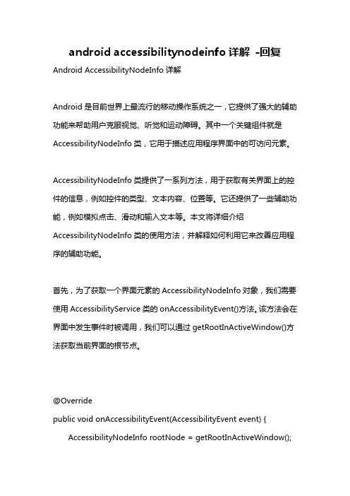
android accessibilitynodeinfo详解-回复Android AccessibilityNodeInfo详解Android是目前世界上最流行的移动操作系统之一,它提供了强大的辅助功能来帮助用户克服视觉、听觉和运动障碍。
其中一个关键组件就是AccessibilityNodeInfo类,它用于描述应用程序界面中的可访问元素。
AccessibilityNodeInfo类提供了一系列方法,用于获取有关界面上的控件的信息,例如控件的类型、文本内容、位置等。
它还提供了一些辅助功能,例如模拟点击、滑动和输入文本等。
本文将详细介绍AccessibilityNodeInfo类的使用方法,并解释如何利用它来改善应用程序的辅助功能。
首先,为了获取一个界面元素的AccessibilityNodeInfo对象,我们需要使用AccessibilityService类的onAccessibilityEvent()方法。
该方法会在界面中发生事件时被调用,我们可以通过getRootInActiveWindow()方法获取当前界面的根节点。
@Overridepublic void onAccessibilityEvent(AccessibilityEvent event) { AccessibilityNodeInfo rootNode = getRootInActiveWindow();if (rootNode != null) {处理根节点processNode(rootNode);}}在获取到根节点后,我们可以使用许多方法来访问和修改其子节点。
例如,使用getChildCount()方法可以获取根节点的子节点数量。
private void processNode(AccessibilityNodeInfo nodeInfo) { if (nodeInfo.getChildCount() > 0) {for (int i = 0; i < nodeInfo.getChildCount(); i++) {AccessibilityNodeInfo childNodeInfo =nodeInfo.getChild(i);处理子节点processNode(childNodeInfo);}}}在遍历子节点时,我们可以使用getChild()方法来获取具体的子节点,并使用getParent()方法来获取父节点。
initialcontextsetuprequest -回复

initialcontextsetuprequest -回复【initialcontextsetuprequest】是什么意思?在计算机科学和网络通信领域,术语【initialcontextsetuprequest】通常用于描述在建立网络连接或通信之前,客户端和服务器之间进行的初始上下文设置请求。
这是一个重要的步骤,旨在确保客户端和服务器之间的通信能够顺利进行。
在这篇文章中,我们将逐步回答有关【initialcontextsetuprequest】的一些关键问题,以帮助读者更好地理解它的作用和实施过程。
1. 什么是【initialcontextsetuprequest】?【initialcontextsetuprequest】是客户端向服务器发送的一个初始化上下文设置请求的消息。
该请求包含了客户端的一些基本参数和设置要求,以便服务器在接收到请求后能够根据这些信息进行合适的配置。
2. 为什么需要进行【initialcontextsetuprequest】?【initialcontextsetuprequest】的目的是确保客户端和服务器之间建立起适合双方通信的初始上下文环境。
在建立网络连接或通信之前,双方需要了解对方的设置和参数,以确保通信的顺利进行。
通过发送【initialcontextsetuprequest】,客户端可以指定一些自定义的配置要求,从而满足其特定的需求。
3. 【initialcontextsetuprequest】的实施过程是怎样的?实施【initialcontextsetuprequest】通常涉及以下步骤:第一步:客户端与服务器建立初始连接。
客户端首先与服务器建立连接,以便进行后续的通信。
这可能涉及到基本的网络协议,如TCP/IP。
第二步:客户端发送【initialcontextsetuprequest】。
一旦建立了连接,客户端会向服务器发送【initialcontextsetuprequest】的消息。
materialdesigninxaml框架用户管理 -回复

materialdesigninxaml框架用户管理-回复MaterialDesignInXaml框架用户管理MaterialDesignInXaml是一个为WPF应用程序提供现代化UI风格的框架。
它基于Google的Material Design规范,提供了丰富的控件和样式,使开发人员可以轻松地创建漂亮和一致的用户界面。
在使用MaterialDesignInXaml框架开发应用程序时,用户管理是一个重要的功能模块。
本文将一步一步回答使用MaterialDesignInXaml框架实现用户管理的相关问题。
第一步:引入MaterialDesignInXaml框架首先,我们需要在项目中引入MaterialDesignInXaml框架。
可以通过NuGet包管理器或手动将相关文件添加到项目中来完成引入。
第二步:设计用户管理界面接下来,我们需要设计用户管理界面。
可以使用MaterialDesignInXaml 框架提供的样式和控件来创建现代化的用户界面。
例如,可以使用Card 控件来显示用户信息,使用TextBox和Button控件来实现输入和操作功能,使用Snackbar控件来显示操作结果等。
第三步:创建用户对象在用户管理功能中,我们需要创建一个用户对象来表示用户信息。
可以定义一个名为User的类,包含用户的相关属性,如用户名、密码、角色等。
csharppublic class User{public string Username { get; set; }public string Password { get; set; }public string Role { get; set; }}第四步:使用DataGrid控件显示用户列表接下来,我们需要使用DataGrid控件来显示用户列表。
DataGrid是WPF 中常用的数据显示控件,可以方便地展示多行多列的数据。
可以绑定一个User集合到DataGrid的ItemsSource属性上,将用户列表显示在界面上。
- 1、下载文档前请自行甄别文档内容的完整性,平台不提供额外的编辑、内容补充、找答案等附加服务。
- 2、"仅部分预览"的文档,不可在线预览部分如存在完整性等问题,可反馈申请退款(可完整预览的文档不适用该条件!)。
- 3、如文档侵犯您的权益,请联系客服反馈,我们会尽快为您处理(人工客服工作时间:9:00-18:30)。
Technical Note 483: Accessing UI Context and Non UI Context Object InstancesBackgroundThis document describes how Siebel applications instantiate objects to support the user interface (UI) and how these objects can be accessed from a script to implement business functions. It also describes how objects can be created "out of the UI context" to perform actions that are not immediately reflected in the UI.A good understanding of the difference between UI and non-UI context objects allows developers to instantiate objects in the right way depending on the business needs.1. UI Context objectsUI Context object instances are automatically created and destroyed by the Siebel application to support the rendering of a view.When a view is displayed in the UI, a business object instance is created in the UI context. Business component instances are created in the UI context for each applet in the view.All operations performed on a UI context object will be immediately reflected in the UI.For example:If bc has been instantiated in the UI context, the following eScript code will perform a requery in the current view and the UI will be affected by the query.Last Modified:3 October 2003Area(s):Siebel VB/eScript/Browser Script/COM Release(s):V7 (Enterprise)Database(s):All Supported Databases App Server OS(s):All Supported Platforms Latest release tested against:V7 (Enterprise)Keywords:UI context ActivateFieldbc.ClearToQuery();bc.ExecuteQuery();An operation like the example listed below will change the field "Name" in the UI and the user will immediately notice that this field has been updated.bc.SetFieldValue ("Name", "New Name" );Note: Operations that require the UI to be updated need to be performed using UI-context objects.1.1. Accessing UI context objectsSiebel applications provide methods to access UI objects from browser scripts and server scripts. The examples provided in this document assume that the language selected for server scripts is eScript.To access the business object in the UI context, the following methods are available:Application.ActiveBusObject, Buscomp.BusObject.Example:To access a business component in the UI context, the following methods are available:Application.ActiveBusComp, Applet.BusObject, BusObject.GetBusComp.Example: (code in Account Entry Applet PreInvokeMethod browser event)(*) ActiveBusComp is only supported in browser script1.2. Accessing field values from UI context business components.In order to access a field using .GetFieldValue method, the field needs to be activated.In browser scripting, only those fields being displayed in the view are activated. The exception to this rule is ID field which is always active and can be retrieved.In server scripting, the following fields can be retrieved from a UI-context buscomp:z System fields, like Id, Created, Created Byz Fields exposed in the UIz Fields with Force Active property = Truez Fields with Link Spec property = TrueIMPORTANT: Do not use ActivateField method to activate a field in a UIcontext business component. This may cause some unwanted sideeffects.2. Non-UI Context objectsNon UI context objects are created by code. The instances are non-visual. That is, they have no associated UI components. When a non UI context object is used to perform certain task, the result is not noticed by the user in the current view.Non UI context business components are used to perform tasks involving other business components that are not shown in the UI.When the current record is instantiated and modified in the UI context, a warning message appears which indicates that the current record has been modified by either another user or a process running out of the UI context. In order to see the new values of the fields the user may refresh the record by executing a query."The selected record has been modified by another user since it was retrieved."The following examples require the use of a Non-UI Context business component:z Invisibly querying a BC that is visible in the UI.{Querying data in a BC without the user seeing any change in the applet(s){Process many records in the backgroundz Using a BC in a different BO contextA business component is needed that represents the child/detail records for a parent/master other than thecurrent parent/master (Uses a different link)2.1. Accessing Non UI context objectsNon UI context business objects and business components can be created from server scripts using themethods: Application.GetBusObject and BusComp.GetBusComp .For example:var BO = TheApplication().GetBusObject("Opportunity");var OppBC = BO.GetBusObject("Opportunity");var ActBC = BO.GetBusComp("Action");GetBusObject is not supported in browser script. However, it is possible to call an applet or buscomp method that has been implemented in server scripting from a browser script.2.2. Accessing field values from Non UI context business componentsIn order to access a field using .GetFieldValue method, the field needs to be activated.In server scripting, the following fields can be retrieved from a Non UI-context buscomp: z System fields, like Id, Created, Created Byz Fields with Force Active property = Truez Fields with Link Spec property = Truez Fields that have been activated in code using ActivateField methodFor example:var ActBC = BO.GetBusComp("Action");ActBC.ClearToQuery();ActBC.ActivateField("Status");ActBC.ActivateField("Date Modified");…ActBC.ExecuteQuery();If (ActBC.FirstRecord()){var sStatus = ActBC.GetFieldValue("Status");…}IMPORTANT : Use ActivateField method BEFORE executing a query orcreating a new record using NewRecord. DO NOT use ActivateFieldAFTER executing the query or after a NewRecord.。