Rectifier
填谷电路工作原理

填谷电路工作原理填谷电路(bridge rectifier)是一种用于将交流电转换为直流电的电路。
它由四个二极管组成,通常被称为整流桥。
填谷电路的工作原理是利用四个二极管的导通状态来将交流电从两个方向上同时整流为直流电。
首先,让我们来探讨填谷电路的组成部分。
填谷电路由四个二极管组成,这些二极管通常被标记为D1、D2、D3和D4、而交流电则通过两个导体进入填谷电路,这两个导体通常被标记为A和B。
填谷电路的工作原理可以通过以下步骤来解释:1.正半周:在正半周期,导体A被连接到电源的正极,导体B则连接到电源的负极。
二极管D1和D4由于正向偏置而处于导通状态,它们允许电流从导体A流向负极,并进入导体B。
与此同时,二极管D2和D3由于反向偏置而处于关断状态,它们阻止电流从导体B流向导体A。
因此,在正半周期内,电流只能从导体A流向导体B。
2.负半周:在负半周期中,导体A连接到电源的负极,导体B连接到电源的正极。
这次,二极管D2和D3由于正向偏置而处于导通状态,它们允许电流从导体B流向导体A。
与此同时,二极管D1和D4由于反向偏置而关闭,它们阻止电流从导体A流向导体B。
因此,在负半周期中,电流只能从导体B流向导体A。
通过这两个半周期的连续切换,填谷电路将交流电从两个方向上同时整流为直流电。
填谷电路的主要优点是:1.高效性:填谷电路几乎可以充分利用交流电的全部能量,因为它可以同时整流来自两个方向的电流。
2.增加电压:填谷电路通过将四个二极管连接在一起形成一个桥路,可以增加整流电路的电压容量。
这样可以支持更大电流和功率的应用。
3.可靠性:填谷电路中的四个二极管可以分别进行替换,所以如果一个二极管损坏,只需更换该二极管而不需要更换整个电路。
总体而言,填谷电路是将交流电转换为直流电的理想选择。
它可以高效地将交流电整流为直流电,并能够处理更大的电流和功率。
在各种应用中,填谷电路都得到了广泛的应用,例如电源适配器、电机驱动器、变流器和无线充电器等。
Bridge Rectifier 桥式整流器
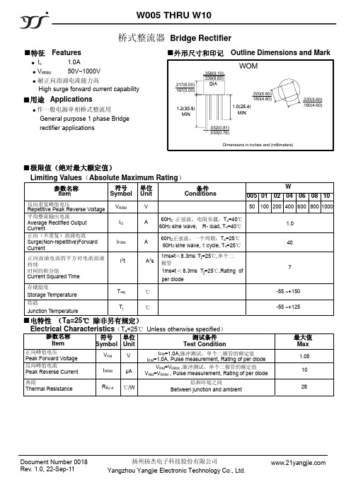
反向重复峰值电压 Repetitive Peak Reverse Voltage 平均整流输出电流
Average Rectified Output Current 正向(不重复)浪涌电流
Surge(Non-repetitive)Forward Current
VRRM IO IFSM
正向浪涌电流的平方对电流浪涌 持续
热阻 Thermal Resistance
RθJ-A ℃/W
结和环境之间 Between junction and ambient
最大值 Max
1.05 10
28
Document Number 0018 Rev. 1.0, 22-Sep-11
扬州扬杰电子科技股份有限公司 Yangzhou Yangjie Electronic Technology Co., Ltd.
A
60HZ 正弦波,电阻负载,Ta=40℃ 60HZ sine wave, R- load, Ta=40℃
1.0
A
60HZ正弦波,一个周期,Ta=25℃ 60HZ sine wave, 1 cycle, Ta=25℃
40
A2s
1ms≤t<8.3ms Tj=25℃,单个二 极管
1ms≤t < 8.3ms Tj=25℃,Rating of
7
per diode
℃
-55 ~+150
℃
-55 ~+125
■电特性 (Ta=25℃ 除非另有规定)
Electrical Characteristics(Ta=25℃ Unless otherwise specified)
参数名称
符号 单位
测试条件
Item
摩托车5大电器件
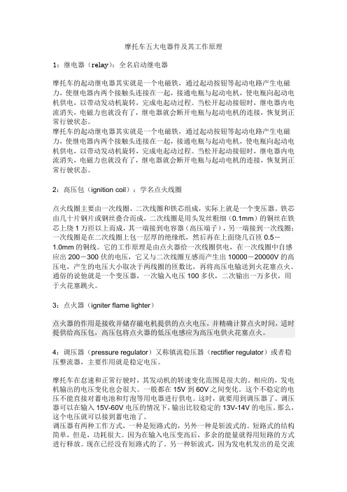
摩托车五大电器件及其工作原理1:继电器(relay):全名启动继电器摩托车的起动继电器其实就是一个电磁铁,通过起动按钮等起动电路产生电磁力,使继电器内两个接触头连接在一起,接通电瓶与起动电机,使电瓶向起动电机供电,以带动发动机旋转,完成电起动过程。
当松开起动接钮时,继电器内电流消失,电磁力也就没有了,继电器就会断开电瓶与起动电机的连接,恢复到正常行驶状态。
摩托车的起动继电器其实就是一个电磁铁,通过起动按钮等起动电路产生电磁力,使继电器内两个接触头连接在一起,接通电瓶与起动电机,使电瓶向起动电机供电,以带动发动机旋转,完成电起动过程。
当松开起动接钮时,继电器内电流消失,电磁力也就没有了,继电器就会断开电瓶与起动电机的连接,恢复到正常行驶状态。
2:高压包(ignition coil):学名点火线圈点火线圈主要由一次线圈、二次线圈和铁芯组成,实际上就是一个变压器。
铁芯由几十片钢片或钢丝叠合而成,二次线圈是用头发丝粗细(0.1mm)的铜丝在铁芯上绕1万匝以上而成,其一端接到电容器(高压端子),另一端接到一次线圈;一次线圈是在二次线圈上包一层厚的绝缘纸,然后再在上面绕几百匝0.5-1.0mm的铜线。
它的工作原理是由点火器给一次线圈供电,在一次线圈中自感应出200-300伏的电压,它又与二次线圈互感而产生出10000-20000V的高压电,产生的电压大小取决于两线圈的匝数比,再将高压电输送到火花塞点火。
通俗的说他就是一个变压器,一次输入电压100多伏,二次输出一万多伏,用于火花塞跳火。
3:点火器(igniter flame lighter)点火器的作用是接收并储存磁电机提供的点火电压,并精确计算点火时间,适时提供给高压包,高压包将点火器的低压电感应为高压电供火花塞点火。
4:调压器(pressure regulator)又称镇流稳压器(rectifier regulator)或者稳压整流器,主要作用就是稳定电压。
IR SmartRectifier IC提升系统效率1.5%
恩 智 浦 展 示 首 款 功 能 性 C r x  ̄ P of - e MO i -
E前 宣 布 推 出 其 最 新 版 本 Liu 平 台 t nx WidR vrLn x3 。 预 集成 、商 用 n ie iu . 0
CE M I 资讯快报 l e &Po u tS o ws r d c s h w N
■置冒
耗 和 最 低 的 物料 成 本 。 带 有US 接 口的UHFR I B F D读卡
器 RU一1 u  ̄ 适 用 于 物 流 、制 造 和 20 t常
零 售 业 应 用 ,其 性 能 早 已 在 一 些亚 洲 市 场 的 闭 环 托 盘 / 箱 跟 踪 系统 中 得 货
以 及 业 界 首 款 面 向E h r e、US 与 的 消 隐 方 案 和 双 脉 冲 抑 制 来 实 现 ,使 提 高 开 发 灵 活 性 , 同 时 控 制 投 资 成 ten t B
级 、全支 持是这个全新Liu 平 台的 nx
三 大 突 出特 色 。 最 新 的 w i d Ri e n x 30 n v rLiu . 基 于 全 新 的 Li u . . 7 核 和 n x 262 内 GCC . 提 供 了 灵 活 、 通 用 的 4 3,
约 的 特 性 使 之 成 为 当 今 市 场上 最 方 便 拓 扑 上 作 为 同 步 整 流 器 ( R S )的 两 个 等 。新 版 L n x 台还 全 面 支 持 最 尖 iu 平 易 用的 架构 之 一 。
N通 道 功 率 M OS ET。 与 传 统 的 变 端 的 多 核 处 理 功 能 ,例 如 基 于 KVM F
肖特基二极管简介

BTA54C BTA54SDO41SCHOTTKY:取第一个字母“S”,SMD:Surface Mounted Devices的缩写,意为:表面贴装器件,取第一个字母“S”,上面两个词组各取第一个字母、即为SS,同普通硅二极管一样,肖特基二极管也是具有单向导电特性的硅二极管。
不同的是,普通二极管的工作是利用半导体PN结的单向导电特性,而肖特基二极管则是利用金属和半导体接触产生的势垒而起到单向导电作用,它在开关没有时存储电荷和移动效应。
所以,肖特基二极管的开关速度非常快,反向恢复时间t rr很短(小于几十ns);同时,其正向压降V F较小,尤其适用于高速开关电路和低压大电流输出电路,具有较高的整流效率和可靠性。
这是肖特基二极管的两大优点,但肖特基二极管也有两个缺点,一是反向耐压V R较低,二是反向漏电流I R较大。
肖特基的最高电压是200V,也就是说,肖特基的极限电压是200V。
超过200V电压的也必定是模块。
电流越大,电压越低。
与可控硅元件不一样。
电流与电压成反比(模块除外)。
10A、20A、30A规格的有做到200V电压。
电流最小的肖特基是BAT42(0.2A);BAT54、BAT54A、BAT54C(0.3A);电流最大的肖特基是440A,如:440CMQ030、444CNQ045;超过440A的必定是模块。
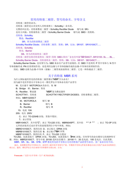
关于肖特基MBR系列为什么国际通用常见的肖特基二极管都以“MBR”字头命名?因为最早是摩托罗拉产品型号M:是以最早MOTOROLA的命名,取MB:Bridge 桥;Barrier:势垒R:Rectifier,整流器“MBR”意为整流器件例如:MBR10200CTM:MOTOROLA 缩写MB:Barrier缩写BR:Rectifier 缩写R10:电流10A200:电压200VC:表示TO-220AB封装,常指半塑封。
T:表示管装MBR1045CT,其中的“C”:表示TO-220封装;MBR6045PT,其中的“P”:表示TO-3P封装元件的封装形式也在型号的前缀第四位字母中体现,例如:MBRD10100CT:第四位的D,表示贴片DPAK封装,即TO-252MBRB10100CT:第四位的B,表示贴片D2PAK封装,即TO-263MBRF10100CT:第四位的F,表示TO-220F全塑封MBR、SR、SL、SB、STB、STP都是常见的半导体公司对肖特基产品的型号命名。
IR扩展SmartRectifier IC系列
Vsa ih y推 出具 有 超低 前 向压 降 的
小 型 肖 特 基 整 流 器
L 23 TC 6 4的 小 尺 寸 和 内 部 基 准 对 各 种 工 业 、 车 和 汽 ATE应 用 来 说都 很 重 要 。L TC2 3 6 4具有 ±2 5 S ( 大 .L B 最 值 )I 差 和 <2 4 n ・S串 扰 的 1 NI误 . V 2位 性 能 , 而 确 保 从
Vih y推 出 两款 新 型 肖特 基 整 流 器 —— MS 1 2 和 sa SP U 在 一 个 DAC上 的 电 压 变化 对 另 一 个 DAC产 生 最 小 影 响 。 MS 1 3 在 + 8 ℃ 和 + 2 ℃ 时 的 前 向 压 降 分 别 只 有 S P U, 5 5 L 23 TC 6 4用 2 7 . 的单 电源 工 作 , 源 电流 很 低 , . ~5 5V 电 每 0 3 . 5V和 0 4 V。 器 件 采 用 小 型 M i o MP功 率 封 装 , . c S r 额 个 DAC 为 1 5/ 2 a A。 定 电压 分 别 为 2 MS 1 2 和 3 MS 1 3 , 出 0V( S P u) 0V( S P U) 输
以及 8 6 8V 的宽 泛 Vc . ~1 c操作 范 围 。 品 。L TC2 3 6 4加 上 之 前 推 出 的 L 2 3 TC 6 6八 通 道 DAC 和 迟 , L 2 3 / 2 4 TC 6 0 I TC 6 0单 通 道 DAC, 众 多 应 用 提 供 了 小 体 为
保 ( 4A 微 集成了一个精确 的基 准。L 23 TC 6 4是 凌 力 尔 特 公 司 具 有 动 逻 辑 和 uVI) 护 、 峰 值 关 闭 门驱 动 电 流 、 功 率 1 . 7 s 内部基准 的纤巧 1 2位 、 0位 和 8位 DAC 系 列 的 最 新 产 启 动 和 超 低 静 态 电流 、 O 7V 门驱 动钳 、 0 n 关 闭传 播 延 1
什么是可控硅(Whatissiliconcontrolledrectifier)

什么是可控硅(What is silicon controlled rectifier)晶闸管又叫可控硅(可控硅整流,可控硅)。
自从20世纪50年代问世以来已经发展成了一个大的家族,它的主要成员有单向晶闸管、双向晶闸管、光控晶闸管、逆导晶闸管、可关断晶闸管、快速晶闸管,等等。
今天大家使用的是单向晶闸管,也就是人们常说的普通晶闸管,它是由四层半导体材料组成的,有三个PN结,对外有三个电极〔图2(一)〕:第一层P型半导体引出的电极叫阳极,第三层P型半导体引出的电极叫控制极G,第四层N型半导体引出的电极叫阴极K.从晶闸管的电路符号〔图2(b)〕可以看到,它和二极管一样是一种单方向导电的器件,关键是多了一个控制极G,这就使它具有与二极管完全不同的工作特性。
可控硅二、晶闸管的主要工作特性为了能够直观地认识晶闸管的工作特性,大家先看这块示教板(图3)。
晶闸管VS与小灯泡EL串联起来,通过开关的接在直流电源上。
注意阳极一是接电源的正极,阴极K接电源的负极,控制极G通过按钮开关某人接在3v直流电源的正极(这里使用的是kp5型晶闸管,若采用KP1型,应接在1.5v直流电源的正极)。
晶闸管与电源的这种连接方式叫做正向连接,也就是说,给晶闸管阳极和控制极所加的都是正向电压。
现在我们合上电源开关,小灯泡不亮,说明晶闸管没有导通;再按一下按钮开关某人,给控制极输入一个触发电压,小灯泡亮了,说明晶闸管导通了。
这个演示实验给了我们什么启发呢?可控硅这个实验告诉我们,要使晶闸管导通,一是在它的阳极一与阴极K之间外加正向电压,二是在它的控制极G与阴极K之间输入一个正向触发电压。
晶闸管导通后,松开按钮开关,去掉触发电压,仍然维持导通状态。
晶闸管的特点:是”一触即发”。
但是,如果阳极或控制极外加的是反向电压,晶闸管就不能导通。
控制极的作用是通过外加正向触发脉冲使晶闸管导通,却不能使它关断。
那么,用什么方法才能使导通的晶闸管关断呢?使导通的晶闸管关断,可以断开阳极电源(图3中的开关S)或使阳极电流小于维持导通的最小值(称为维持电流)。
肖特基二极管、型号的命名、字母含义、解释
肖特基二极管、型号的命名、字母含义、解释肖特基二极管的命名:肖特基二极管是以其发明人肖特基博士(Schottky)命名的,完整的叫法是:肖特基整流二极管(Schottky Rectifier Diode 缩写成 SR),也有人叫做:肖特基势垒二极管(Schottky Barrier Diode 缩写成 SBD)的简称。
肖特基:Schottky整流:RectifierSR:即为肖特基整流二极管Schottky Rectifier Diode:肖特基整二极管,简称:SR,比如:SR107,SR10100CT......肖特基:Schottky势垒:BarrierSB:即为肖特基势垒二极管肖特基二极管也称肖特基势垒二极管(简称SBD),国内厂家也有叫做“SB1045CT、SR10100、SL....、BL....Schottky Barrier Diode:肖特基势垒二极管,简称:SB,比如:SB107,SB1045CT......Schottky Barrier Diode:也有简写为:SBD 来命名产品型号前缀的。
但 SBD 不是利用 P 型半导体与 N 型半导体接触形成PN 结原理制作的,而是利用金属与半导体接触形成的金属-半导体结原理制作的。
因此,SBD 也称为金属-半导体(接触)二极管或表面势垒二极管,它是一种热载流子二极管。
关于肖特基 MBR 系列为什么国际通用常见的肖特基二极管都以“MBR”字头命名?因为最早是世界著名半导体公司-摩托罗拉半导体命名的产品型号M:是以最早 MOTOROLA 的命名,取 MB:Bridge 桥;Barrier:势垒R:Rectifier,整流器“MBR”意为整流器件SCHOTTKY:肖特基 SCHOTTKY RECTIFIER DIODES:肖特基整流二极管。
例如:MBR10200CT M:MOTOROLA 缩写 MB:Barrier1 缩写 BR:Rectifier 缩写 R10:电流 10A200:电压 200VC:表示 TO-220AB 封装,常指半塑封。
Rectifier原理讲解
直流变换器有非电气隔离型和有电气隔离型两类。 以所用功率开关管的数量来分类,单管非隔离直 流变换器有六种基本类型,即降压式(Buck)、 升压式(BOOST)、升降压式(Buck/Boost)、 库克(Cuk)、瑞泰(Zeta)和赛皮克(Sepic)。 双管直流变换器有双管串接的升降压式 (Buck/Boost)。全桥变换器(Full-bridge converter)是常用的四管直流变换器。 隔离型直流变换器也可以用功率管数量来非类。 典型单管隔离直流变换器有正激变换(Forward) 和反激变换(Flyback),双管变换有双管正激 (Double transistor forward converter)、双管反 激变换(Double transistor flyback converter)、 推挽(Push-pull converter)和半桥(Half-bridge converter)。四管直流变换是全桥变换(Fullbridge converter)。
PFC电路工作原理
• 拓扑图的介绍
工作原理如下: 开关管以UC3842设定的频率周期开闭,使电感L储存能量 并释放能量。当开关管导通时,电感以V1/L的速度充电, 把能量储存在L中。当开关截止时,L产生反向感应电压, 通过二极管D把储存的电能以(Vo-Vi)/L的速度释放到输 出电容器C2中。输出电压由传递的能量多少来控制,而 传递能量的多少通过电感电流的峰值来控制。 整个稳压过程由二个闭环来控制,即 闭环1 输出电压通过取样后反馈给误差放大器,用于 同放大器内部的2.5V基准电压比较后产生误差电压,误差 放大器控制由于负载变化造成的输出电压的变化。 闭环2 Rs为开关管源极到公共端间的电流检测电阻, 开关管导通期间流经电感L的电流在Rs上产生的电压送至 PWM比较器同相输入端,与误差电压进行比较后控制调 制脉冲的脉宽,从而保持稳定的输出电压。误差信号实际 控制着峰值电感电流。
常用肖特基二极管、型号的命名、字母含义
SCHOTTKY RECTIFIER DIODES:肖特基整流二极管。
例如:MBR10200CT
M:MOTOROLA
缩写 M
B:Barrier1
缩写 B
R:Rectifier
缩写 R
10:电流 10A
200:电压 200V
C:表示 TO-220AB 封装,常指半塑封。
T:表示管装
MBR1045CT,其中的“C”:表示 TO-220 封装;MBR6045PT,其中的“P”:表示 TO-3P 封装
MBR30150CT,30A,150V,TO-220AB、TO-220F 全塑封;
MBR30200CT,30A,200V,TO-220AB、TO-220F 全塑封;
MBR3045PT, 30A, 45V,TO-247、TO-3P;
MBR3060PT, 30A, 60V,TO-247、TO-3P;
MBR30100PT,30A,100V,TO-247、TO-3P;
MBR1045CT、MBR10100CT:TO-220AB(三脚半塑封),10A
M
BMBR1535CT、MBR1545CT:TO-220AB(三脚),15A RFMBR2045CT、MBR20200CT:TO-220AB(三脚),20A 1MBR2535CT、MBR2545CT:TO-220AB(三脚),25A 0MBR3045CT、MBR3060CT:TO-220AB(三脚),30A
MBR40150PT,40A,150V,TO-247、TO-3P;
MBR40200PT,40A,200V,TO-247、TO-3P;
MBR6045PT, 60A, 45V,TO-247、TO-3P;
MBR6060PT, 60A, 60V,TO-247、TO-3P;
scr原理
scr原理SCR原理。
Silicon Controlled Rectifier (SCR)是一种半导体器件,它具有双向导电性能,可以控制大电流。
SCR主要由四个层级的P型和N型半导体材料构成,通过控制触发电压,可以实现对电流的控制。
SCR广泛应用于电力控制和电子设备中,其原理和特性对于电子工程师和电气工程师来说是非常重要的。
SCR的工作原理基于PN结和电流控制的特性。
当PN结处于正向偏置状态时,SCR处于导通状态,可以通过控制触发电压来实现对电流的控制。
当施加在门极上的电压超过一定的触发电压时,PN结会出现击穿,形成导通通道,从而使得SCR导通。
在这种情况下,SCR将一直处于导通状态,直到电流下降到零或者施加在阳极和门极之间的电压下降到一定程度。
SCR的特性主要包括触发特性、导通特性和关断特性。
触发特性是指在施加在门极上的电压超过一定的触发电压时,SCR将导通。
导通特性是指一旦SCR导通,它将一直保持导通状态,直到电流下降到零或者施加在阳极和门极之间的电压下降到一定程度。
关断特性是指当施加在门极上的电压下降到一定程度时,SCR将停止导通。
SCR的应用非常广泛,主要包括电力控制、电动机控制、电压调节和交流电转直流电等方面。
在电力控制方面,SCR可以用于实现电流的调节和开关控制,从而实现对电力系统的精确控制。
在电动机控制方面,SCR可以用于实现电动机的启动、调速和制动,提高电动机的效率和可靠性。
在电压调节方面,SCR可以用于实现对电压的精确调节,保护电子设备不受过电压的损害。
在交流电转直流电方面,SCR可以用于实现交流电到直流电的变换,满足不同设备对电源的需求。
总之,SCR作为一种重要的半导体器件,在电力控制和电子设备中发挥着重要作用。
了解SCR的原理和特性对于电子工程师和电气工程师来说是非常重要的,可以帮助他们更好地设计和应用电子电路,提高电力系统的效率和可靠性。
希望本文对于SCR的原理有所帮助,谢谢阅读!。
RS1A B - RS1M B 1.0A SMT快恢复晶体极 Rectifier 产品说明书

Features• Glass Passivated Die Construction • Fast Recovery Time for High Efficiency • Surge Overload Rating to 30A Peak • Ideally Suited for Automated Assembly• Lead-Free Finish; RoHS Compliant (Notes 1 & 2)•Halogen and Antimony Free. “Green” Device (Note 3)Mechanical Data• Case: SMA/SMB• Case Material: Molded Plastic.UL Flammability Classification Rating 94V-0 • Moisture Sensitivity: Level 1 per J-STD-020• Terminals: Finish - Matte Tin Annealed over Copper Alloy Leadframe; Solderable per MIL-STD-202, Method 208 • Polarity: Cathode Band or Cathode Notch •Weight: SMA - 0.064 grams (Approximate) SMB - 0.093 grams (Approximate)SMA/SMBOrdering Information (Note 4)Part Number Case Packaging RS1x-13-F SMA 5000/Tape & Reel RS1xB-13-FSMB 3000/Tape & Reel* x = Device type, e.g. RS1D-13-F (SMA package); RS1JB-13-F (SMB package).Notes: 1. EU Directive 2002/95/EC (RoHS), 2011/65/EU (RoHS 2) & 2015/863/EU (RoHS 3) compliant. All applicable RoHS exemptions applied.2. See https:///quality/lead-free/ for more information about Diodes Incorporated’s definitions of Halogen- and Antimony-free, "Green" and Lead-free.3. Halogen- and Antimony-free "Green” products are defined as those which contain <900ppm bromine, <900ppm chlorine (<1500ppm total Br + Cl) and <1000ppm antimony compounds.4. For packaging details, go to our website at https:///design/support/packaging/diodes-packaging/.Marking InformationSMA/SMBTop View Bottom ViewRS1x = Product Type Marking Code, ex: RS1G (SMA Package) RS1xB = Product Type Marking Code, ex: RS1GB (SMB Package) = Manufacturer’s Code Marking YWW = Date Code MarkingY = Last Digit of Year (ex: 9 for 2019) WW = Week Code (01 to 53)Maximum Ratings(@T A = +25°C, unless otherwise specified.) Single phase, half wave, 60Hz, resistive or inductive load.For capacitive load, derate current by 20%.Characteristic Symbol RS1A/ABRS1B/BBRS1D/DBRS1G/GBRS1J/JBRS1K/KBRS1M/MBUnitPeak Repetitive Reverse Voltage Working Peak Reverse Voltage DC Blocking Voltage (Note 5) V RRMV RWMV R50 100 200 400 600 800 1000 VRMS Reverse Voltage V R(RMS)35 70 140 280 420 560 700 V Average Rectified Output Current @ T T = +120°C I O 1.0 A Non-Repetitive Peak Forward Surge Current, 8.3msSingle Half Sine-Wave Superimposed on Rated Load I FSM30 AThermal CharacteristicsCharacteristic Symbol Value Unit Typical Thermal Resistance, Junction to Terminal (Note 6) RϴJT20 °C/W Operating and Storage Temperature Range T J, T STG-65 to +150 °CElectrical Characteristics(@T A = +25°C unless otherwise specified.)Characteristic Symbol RS1A/ABRS1B/BBRS1D/DBRS1G/GBRS1J/JBRS1K/KBRS1M/MBUnitMinimum Reverse Breakdown Voltage (Note 5) @ I R = 5µA V(BR)R50 100 200 400 600 800 1000 V Maximum Forward Voltage Drop @ I F = 1.0A V FM 1.3 VPeak Reverse Current @ T A = +25°C at Rated DC Blocking Voltage (Note 5) @ T A = +125°C I RM5.0200µAMaximum Reverse Recovery Time (Note 7) t RR150 250 500 ns Typical Total Capacitance (Note 8) C T15 pFNotes: 5. Short duration pulse test used to minimize self-heating effect.6. Valid provided that terminals are kept at ambient temperature.7. Reverse recovery test conditions: I F = 0.5A, I R = 1.0A, I RR = 0.25A. See Figure 5.8. Measured at 1.0MHz and applied reverse voltage of 4.0V DC.1.2I , A V E R A G E R E C T I F I E D C U R R E N T (A )O T , TERMINAL TEMPERATURE (C)Fig. 1 Forward Current Derating CurveT °0.6I I N S T A N T A N E O U S F O R W A R D C U R R E N T (A )F ,V , INSTANTANEOUS FORWARD VOLTAGE (V)Fig. 2 Typical Forward Characteristics F 0I , P E A K F O R W A R D S U R G E C U R R E N T (A )F S M NUMBER OF CYCLES AT 60HzFig. 3 Forward Surge Current Derating Curve 1.01001,000 PERCENT OF RATED PEAK REVERSE VOLTAGE (%)Fig. 4 Typical Reverse Characteristics T = 125C J ° T = 25°C J I , I N S T A N T A N E O U S R E V E R S E C U R R E N T ( µ A ) R I R , I N S T A N T A N E O U S R E V E R S E C U R R E N T (µA )Package Outline DimensionsPlease see /package-outlines.html for the latest version.SMASMBSMBDim Min Max A 3.30 3.94 B 4.06 4.57 C 1.96 2.21 D 0.15 0.31 E 5.00 5.59 G 0.05 0.20 H 0.76 1.52 J 2.00 2.50 All Dimensions in mmSuggested Pad LayoutPlease see /package-outlines.html for the latest version.SMADimensionsValue (in mm) C 4.00 G 1.50 X 2.50 X1 6.50 Y1.70SMB。
IOR Rectifier AN-978 高压悬浮门驱动IC说明书
LEVEL TRANSLATOR
VDD/ VCC LEVEL
TRANSLATOR AND PW
DISCRIMINATOR
PULSE GENERATOR
VDD/ VCC LEVEL
TRANSLATOR AND PW
DISCRIMINATOR DELAY
UV DETECT
VB
UV DETECT
Q
PULSE
LATCH
DISCRIMINATOR
LOGIC Q
Cd-sub
Cb-sub
CBOOT HO
VS
LO
2 COMM
VR VCC
图2: IRS2110的结构图
高端 CMOS
LD MOS (电平转换器)
n+
n+
p
p+
p-well
n-
p
n+ p
p+
Cb-sub p-
COM
n+
n+ p
n-
p+
C d-sub
图 3: 硅横截面显示了寄生电容
有些应用需要用到死区,那么应该使用带有集成死区时间(半桥驱动器)或者高端和低端驱动器 与无源器件相结合的MGD 来提供所需的死区时间,如12节所示。通常,对于导通时和关断时(温 度依赖数据手册所描述那样)的两个通道来说,输入与输出之间的传输延迟大约是一样的。对于 一些正逻辑关断的MGD(譬如,IRS2110)来说,输出将内部被关断。关断时间由关断脚上的脉 冲宽度决定。
汽车sbr电路原理
汽车sbr电路原理
SBR电路原理在汽车电子领域中发挥着重要作用。
SBR是指垂直结型整流器(Schottky Barrier Rectifier)的简称。
它是一种特殊的二极管,利用金属与半导体之间的肖特基势垒来实现整流功能。
SBR电路原理有以下几个关键特点和优势。
SBR电路具有低开启压降特性。
相比传统的整流器,SBR电路能够在工作时产生更低的电压降,这意味着更高的效率和更低的功耗。
这对于汽车电子系统来说尤为重要,因为它可以减少能量损失,提高整体系统的效能。
SBR电路还具有快速开关特性。
由于SBR的整流速度较快,能够在很短的时间内从导通到截断,这使得它在汽车电子系统中的开关应用方面具有很大优势。
例如,在电动汽车的电池管理系统中,快速开关的特性可以帮助控制电池充电和放电的过程,确保高效率和安全性。
SBR电路还具有较低的反向漏电流。
在汽车电子系统中,稳定的电源和可靠的电流控制是至关重要的。
SBR的构造使其具有较低的反向漏电流,能够提供更稳定的电源供应,并减少不必要的功耗。
还有一个重要的特点是SBR电路具有较高的温度容限。
在汽车中,各种电子组件会受到高温的影响。
采用SBR电路可以有效地应对高温环境下的性能变化,并保持其可靠性和稳定性。
SBR电路原理在汽车电子领域中具有许多重要优势,包括低开启压降、快速开关、低反向漏电流和高温容限。
这些特点使得SBR电路在汽车电子系统中得到广泛应用,并对整体系统的效率和可靠性产生积极的影响。
三相ac-dc原理
三相ac-dc原理
三相AC-DC转换是一种将三相交流电源转换为直流电源的过程。
这通常通过整流器(Rectifier)来完成。
以下是三相AC-DC转换的基本原理:
1.三相交流电源:原始电源是三相交流电。
在工业和分布式电力系统中,三相电流通常用于提供更为稳定和高效的电力传输。
2.整流器:为了将三相交流电转换为直流电,通常使用整流器。
整流器的任务是将交流电信号的负半周或正半周转换为直流电。
最常见的整流器类型是桥式整流器(Bridge Rectifier)。
3.桥式整流器:桥式整流器包括四个二极管,它们被配置成一个桥形电路。
在每个周期内,桥式整流器选择性地导通其中两个二极管,使得输出电流方向保持单一,从而得到直流电。
4.滤波器:直流电的输出通常会包含一些交流成分,为了减小这些波动,常常在整流器之后添加滤波器。
滤波器可以是电容器,它们平滑输出电压。
5.直流负载:最后,整流器输出的直流电被供给给直流负载,如电机、电池充电器等。
这个过程的优点之一是直流电对某些应用(如电动机和许多电子设备)更为适用,因此通过这种方式可以更有效地使用三相交流电源。
这种转换常见于工业和电力系统中。
广东红星科技有限公司 氧化锂电阻 rectifier SS12F-SS120F 产品说明书
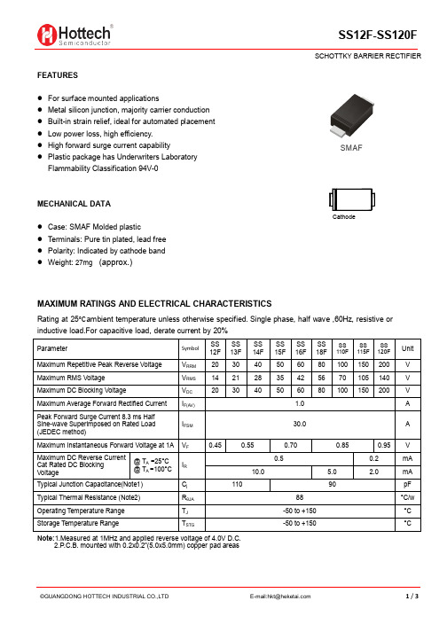
FEATURES● For surface mounted applications● Metal silicon junction, majority carrier conduction ● Built-in strain relief, ideal for automated placement ● Low power loss, high efficiency. ● High forward surge current capability ● Plastic package has Underwriters LaboratoryFlammability Classification 94V-0MECHANICAL DATA● Case: SMAF Molded plastic ● Terminals: Pure tin plated, lead free ● Polarity: Indicated by cathode band ● Weight: 27mg (approx.)MAXIMUM RA TINGS AND ELECTRICAL CHARACTERISTICSRating at 25°C ambient temperature unless otherwise specified. Single phase, half wave ,60Hz, resistive or inductive load.For capacitive load, derate current by 20%Note:1.Measured at 1MHz and applied reverse voltage of 4.0V D.C.2.P .C.B. mounted with 0.2x0.2”(5.0x5.0mm) copper pad areasParameterSymbolSS12F SS 13F SS 14F SS 15F SS 16F SS 18F SS 110F SS 115F SS 120FUnit Maximum Repetitive Peak Reverse Voltage V RRM 20 30 40 50 60 80 100 150 200 V Maximum RMS Voltage V RMS 14 21 28 35 42 56 70 105 140 V Maximum DC Blocking VoltageV DC 2030405060 80100150200V Maximum Average Forward Rectified Current I F(AV) 1.0 A Peak Forward Surge Current 8.3 ms Half Sine-wave Superimposed on Rated Load (JEDEC method)I FSM30.0AMaximum Instantaneous Forward Voltage at 1A V F 0.45 0.55 0.70 0.85 0.95 V Maximum DC Reverse CurrentCat Rated DC BlockingVoltage@ T A =25°C@ T A =100°CI R 0.50.2mA 10.0 5.0 2.0mA Typical Junction Capacitance(Note1) C j 11090pF Typical Thermal Resistance (Note2) R θJA 88 °C/w Operating Temperature Range T J -50 to +150 °C Storage Temperature RangeT STG-50 to +150°CSMAFCathodeTypical Characteristics1.00.80.60.40.20.1 1.0 10 1000.01 0.1 1 10 1001001010.1REVERSE VOLTAGE,VOLTSt,PULSE DURATION,sec.FIG. 5-TYPICAL JUNCTION CAPACITANCEFIG. 6-TYPICAL TRANSIENT THERMAL IMPEDANCENUMBER OF CYCLES AT 60 HzFIG. 2-MAXIMUM NON-REPETITIVE PEAK FORWARDFIG. 1- FORWARD CURRENT DERATING CURVEA V E R A G E F O R W A R D R E C T I F I E D C U R R E N T ,A M PE R E SJ U N C T I O N C A P A C I T A N C E , p FP E A K F O R W A R D S U R G E C U R R E N T ,A M P E R ES1001010.10.010.001PERCENT OF PEAK REVERSE VOLTAGE,%FIG. 4-TYPICAL REVERSE CHARACTERISTICSI N S T A N T A N E O U S R E V E R S E C U R R E N T ,M I L L I A M P E R E ST R A N S I E N T T H E R M A L I M P E D A N C E ,C /WAMBIENT TEMPERATURE, C FIG. 3-TYPICAL INSTANTANEOUS FORWARDCHARACTERISTICSI N S T A N T A N E O U S F O R W A R D C U R R E N T ,A M P E R E SINSTANTANEOUS FORWARD VOLTAGE,VOLTS5010.010.10.01UNITmm1.10.20 3.72.7 4.90.90.123.3 2.44.47°maxminmil maxmin43357.94.714613010694193173A C D E H E∠1.61.36351eBottom View Top View1.20.84731gPackage Outline Dimensions SMAF。
- 1、下载文档前请自行甄别文档内容的完整性,平台不提供额外的编辑、内容补充、找答案等附加服务。
- 2、"仅部分预览"的文档,不可在线预览部分如存在完整性等问题,可反馈申请退款(可完整预览的文档不适用该条件!)。
- 3、如文档侵犯您的权益,请联系客服反馈,我们会尽快为您处理(人工客服工作时间:9:00-18:30)。
RectifierFrom Wikipedia, the free encyclopediaFor other uses, see Rectifier (disambiguation).A rectifier is an electrical device that converts alternating current (AC), which periodically reverses direction,to direct current (DC), which is in only one direction, a process known as rectification. Rectifiers have many uses including as components of power supplies and as detectors of radio signals. Rectifiers may be madeof solid state diodes, vacuum tube diodes, mercury arc valves, and other components.A device which performs the opposite function (converting DC to AC) is known as an inverter.When only one diode is used to rectify AC (by blocking the negative or positive portion of the waveform), the difference between the term diode and the term rectifier is merely one of usage, i.e., the term rectifier describes a diode that is being used to convert AC to DC. Almost all rectifiers comprise a number of diodes in a specific arrangement for more efficiently converting AC to DC than is possible with only one diode. Before the development of silicon semiconductor rectifiers, vacuum tube diodes and copper(I) oxide or selenium rectifier stacks were used.Early radio receivers, called crystal radios, used a "cat's whisker" of fine wire pressing on a crystalof galena (lead sulfide) to serve as a point-contact rectifier or "crystal detector". Rectification may occasionally serve in roles other than to generate direct current per se. For example, in gas heating systems flame rectification is used to detect presence of flame. Two metal electrodes in the outer layer of the flame provide a current path, and rectification of an applied alternating voltage will happen in the plasma, but only while the flame is present to generate it.Half-wave rectificationIn half wave rectification, either the positive or negative half of the AC wave is passed, while the other half is blocked. Because only one half of the input waveform reaches the output, it is very inefficient if used for power transfer. Half-wave rectification can be achieved with a single diode in a one-phase supply, or with three diodes in a three-phase supply.The output DC voltage of a half wave rectifier can be calculated with the following two ideal equations:[1]Full-wave rectificationA full-wave rectifier converts the whole of the input waveform to one of constant polarity (positive or negative) at its output. Full-wave rectification converts both polarities of the input waveform to DC (direct current), and is more efficient. However, in a circuit with a non-center tapped transformer, four diodes are required instead of the one needed for half-wave rectification. (See semiconductors,diode). Four diodes arranged this way are called a diode bridge or bridge rectifier.Graetz bridge rectifier: a full-wave rectifier using 4 diodes.For single-phase AC, if the transformer is center-tapped, then two diodes back-to-back (i.e. anodes-to-anode or cathode-to-cathode) can form a full-wave rectifier. Twice as many windings are required on the transformer secondary to obtain the same output voltage compared to the bridge rectifier above.Full-wave rectifier using a center tap transformer and 2 diodes.Full-wave rectifier, with vacuum tube having two anodes.A very common vacuum tube rectifier configuration contained one cathode and twin anodes inside a single envelope; in this way, the two diodes required only one vacuum tube. The 5U4 and 5Y3 were popular examples of this configuration.A three-phase bridge rectifier.3-phase AC input, half & full wave rectified DC output waveformsFor three-phase AC, six diodes are used. Typically there are three pairs of diodes, each pair, though, is not the same kind of double diode that would be used for a full wave single-phase rectifier. Instead the pairs are in series (anode to cathode). Typically, commercially available double diodes have four terminals so the user can configure them as single-phase split supply use, for half a bridge, or for three-phase use.Disassembled automobile alternator, showing the six diodes that comprise a full-wave three-phase bridge rectifier.Most devices that generate alternating current (such devices are called alternators) generate three-phase AC. For example, an automobile alternator has six diodes inside it to function as a full-wave rectifier for battery charging applications.The average and root-mean-square output voltages of an ideal single phase full wave rectifier can be calculated as:Where:V dc,V av - the average or DC output voltage,V p - the peak value of half wave,V rms - the root-mean-square value of output voltage.π = ~ 3.14159Peak lossAn aspect of most rectification is a loss from the peak input voltage to the peakoutput voltage, caused by the built-in voltage drop across the diodes (around 0.7 Vfor ordinary silicon p-n-junction diodes and 0.3 V for Schottky diodes). Half-waverectification and full-wave rectification using two separate secondaries will have apeak voltage loss of one diode drop. Bridge rectification will have a loss of twodiode drops. This may represent significant power loss in very low voltage supplies.In addition, the diodes will not conduct below this voltage, so the circuit is onlypassing current through for a portion of each half-cycle, causing short segments ofzero voltage to appear between each "hump".Rectifier output smoothingWhile half-wave and full-wave rectification suffice to deliver a form of DC output,neither produces constant-voltage DC. In order to produce steady DC from arectified AC supply, a smoothing circuit or filter is required.[2] In its simplest form thiscan be just a reservoir capacitor or smoothing capacitor, placed at the DC output ofthe rectifier. There will still remain an amount of AC ripple voltage where the voltageis not completely smoothed.RC-Filter Rectifier: This circuit was designed and simulated using Multisim 8 software.Sizing of the capacitor represents a tradeoff. For a given load, a larger capacitor will reduce ripple but will cost more and will create higher peak currents in the transformer secondary and in the supply feeding it. In extreme cases where many rectifiers are loaded onto a power distribution circuit, it may prove difficult for the power distribution authority to maintain a correctly shaped sinusoidal voltage curve. For a given tolerable ripple the required capacitor size is proportional to the load current and inversely proportional to the supply frequency and the number of output peaks of the rectifier per input cycle. The load current and the supply frequency are generally outside the control of the designer of the rectifier system but the number of peaks per input cycle can be affected by the choice of rectifier design.A half-wave rectifier will only give one peak per cycle and for this and other reasons is only used in very small power supplies. A full wave rectifier achieves two peaks per cycle and this is the best that can be done with single-phase input. For three-phase inputs a three-phase bridge will give six peaks per cycle and even higher numbers of peaks can be achieved by using transformer networks placed before the rectifier to convert to a higher phase order.To further reduce this ripple, a capacitor-input filter can be used. This complements the reservoir capacitor with a choke(inductor) and a second filter capacitor, so that a steadier DC output can be obtained across the terminals of the filter capacitor. The choke presents a high impedance to the ripple current.[2]A more usual alternative to a filter, and essential if the DC load is very demanding of a smooth supply voltage, is to follow the reservoir capacitor with a voltage regulator.The reservoir capacitor needs to be large enough to prevent the troughs of the ripple getting below the voltage the DC is being regulated to. The regulator serves both to remove the last of the ripple and to deal with variations in supply and load characteristics. It would be possible to use a smaller reservoir capacitor (these can be large on high-current power supplies) and then apply some filtering as well as the regulator, but this is not a common strategy. The extreme of this approach is to dispense with the reservoir capacitor altogether and put the rectified waveform straight into a choke-input filter. The advantage of this circuit is that the current waveform is smoother and consequently the rectifier no longer has to deal with the current as a large current pulse, but instead the current delivery is spread over the entire cycle. The downside is that the voltage output is much lower – approximately the average of an AC half-cycle rather than the peak.Voltage-doubling rectifiersMain article: voltage doublerThe simple half wave rectifier can be built in two versions with the diode pointing in opposite directions, one version connects the negative terminal of the output direct to the AC supply and the other connects the positive terminal of the output direct to the AC supply. By combining both of these with separate output smoothing it is possible to get an output voltage of nearly double the peak AC input voltage. This also provides a tap in the middle, which allows use of such a circuit as a split rail supply.A variant of this is to use two capacitors in series for the output smoothing on a bridge rectifier then place a switch between the midpoint of those capacitors and one of the AC input terminals. With the switch open this circuit will act like a normal bridge rectifier with it closed it will act like a voltage doubling rectifier. In other words this makes it easy to derive a voltage of roughly 320V (+/- around 15%) DC from any mains supply in the world, this can then be fed into a relatively simple switched mode power supply.Cockcroft Walton Voltage multiplierCascaded stages of diodes and capacitors can be added to make a voltage multiplier (Cockroft-Walton circuit). These circuits can provide a potential several times that of the peak value of the input AC, although limited in current output and regulation. Voltage multipliers are used to provide the high voltage for a CRT in a television receiver, or for powering high-voltage tubes such as image intensifiers or photo multipliers.ApplicationsA rectifier diode (silicon controlled rectifier) and associated mounting hardware. The heavy threaded stud helps remove heat.The primary application of rectifiers is to derive DC power from an AC supply. Virtually all electronic devices require DC, so rectifiers find uses inside the power supplies of virtually all electronic equipment.Converting DC power from one voltage to another is much more complicated. One method of DC-to-DC conversion first converts power to AC (using a device called an inverter), then use a transformer to change the voltage, and finally rectifies power back to DC.Rectifiers also find a use in detection of amplitude modulated radio signals. The signal may be amplified before detection, but if un-amplified, a very low voltage drop diode must be used. When using a rectifier for demodulation the capacitor and load resistance must be carefully matched. Too low a capacitance will result in the high frequency carrier passing to the output and too high will result in the capacitor just charging and staying charged.Output voltage of a full-wave rectifier with controlled thyristorsRectifiers are also used to supply polarised voltage for welding. In such circuits control of the output current is required and this is sometimes achieved by replacing some of the diodes in bridge rectifier with thyristors, whose voltage output can be regulated by means of phase fired controllers.Thyristors are used in various classes of railway rolling stock systems so that fine control of the traction motors can be achieved. Gate turn-off thyristors are used to produce alternating current from a DC supply, for example on the Eurostar Trains to power the three-phase traction motors.[3]Rectification technologiesElectromechanicalEarly power conversion systems were purely electro-mechanical in design, since electronic devices were not available to handle significant power. Mechanical rectification systems usually rely on some form of rotation or resonant vibration in order to move quickly enough to match the frequency of the input power source, and cannot operate beyond several thousand cycles per second.Due to the complexity of mechanical systems, they have traditionally needed a high level of maintenance to keep operating correctly. Moving parts will have friction, which requires lubrication and replacement due to wear. Opening mechanical contacts under load results in electrical arcs and sparks that heat and erode the contacts.Synchronous rectifierTo convert AC currents into DC current in electric locomotives, a synchronous rectifier may be used[citation needed]. It consists of a synchronous motor driving a set of heavy-duty electrical contacts. The motor spins in time with the AC frequency andperiodically reverses the connections to the load just when the sinusoidal current goes through a zero-crossing. The contacts do not have to switch a large current, but they need to be able to carry a large current to supply the locomotive'sDC traction motors.VibratorIn the past, the vibrators used in battery-to-high-voltage-DC power supplies often contained a second set of contacts that performed synchronous mechanical rectification of the stepped-up voltage.Motor-generator setMain articles: Motor-generator and Rotary converterA motor-generator set, or the similar rotary converter, is not a rectifier in the sense that it doesn't actually rectify current, but rather generates DC from an AC source. In an "M-G set", the shaft of an AC motor is mechanically coupled to that of aDC generator. The DC generator produces multiphase alternating currents inits armature windings, and a commutator on the armature shaft converts these alternating currents into a direct current output; or a homopolar generator produces a direct current without the need for a commutator. M-G sets are useful for producing DC for railway traction motors, industrial motors and other high-current applications, and were common in many high power D.C. uses (for example, carbon-arc lamp projectors for outdoor theaters) before high-power semiconductors became widely available.ElectrolyticThe electrolytic rectifier[4] was an early device from the 1900s that is no longer used. When two different metals are suspended in an electrolyte solution, it can be found that direct current flowing one way through the metals has less resistance than the other direction. These most commonly used an aluminum anode, and a lead or steel cathode, suspended in a solution of tri-ammonium ortho-phosphate.The rectification action is due to a thin coating of aluminum hydroxide on the aluminum electrode, formed by first applying a strong current to the cell to build up the coating. The rectification process is temperature sensitive, and for best efficiency should not operate above 86 °F (30 °C). There is also a breakdown voltage where the coating is penetrated and the cell is short-circuited. Electrochemical methods are often more fragile than mechanical methods, and canbe sensitive to usage variations which can drastically change or completely disrupt the rectification processes.Similar electrolytic devices were used as lightning arresters around the same era by suspending many aluminium cones in a tank of tri-ammomiumortho-phosphate solution. Unlike the rectifier, above, only aluminium electrodes were used, and used on A.C., there was no polarization and thus no rectifier action, but the chemistry was similar.[5]The modern electrolytic capacitor, an essential component of most rectifier circuit configurations was also developed from the electrolytic rectifier.Plasma typeMercury arcMain article: Mercury arc valveA rectifier used in high-voltage direct current power transmission systems and industrial processing between about 1909 to 1975 is a mercury arcrectifier or mercury arc valve. The device is enclosed in a bulbous glass vessel or large metal tub. One electrode, the cathode, is submerged in a pool of liquid mercury at the bottom of the vessel and one or more high purity graphite electrodes, called anodes, are suspended above the pool. There may be several auxiliaryelectrodes to aid in starting and maintaining the arc. When an electric arc is established between the cathode pool and suspended anodes, a stream of electrons flows from the cathode to the anodes through the ionized mercury, but not the other way. [In principle, this is a higher-power counterpart to flame rectification, which uses the same one-way current transmission properties of the plasma naturally present in a flame].These devices can be used at power levels of hundreds of kilowatts, and may be built to handle one to six phases of AC current. Mercury arc rectifiers have been replaced by silicon semiconductor rectifiers and high power thyristor circuits, from the mid 1970s onward. The most powerful mercury arc rectifiers ever built were installed in the Manitoba Hydro Nelson River Bipole HVDC project, with a combined rating of more than 1 GW and 450 kV.[6][7]Argon gas electron tubeThe General Electric Tungar rectifier was an argon gas-filled electron tube device with a tungsten filament cathode and a carbon button anode. It was useful for battery chargers and similar applications from the 1920s until low-cost solid-state rectifiers (the metal rectifiers at first) supplanted it. These were made up to a few hundred volts and a few amperes rating, and in some sizes strongly resembledan incandescent lamp with an additional electrode.The 0Z4 was a gas-filled rectifier tube commonly used in vacuum tube car radios in the 1940s and 1950s. It was a conventional full wave rectifier tube with two anodes and one cathode, but was unique in that it had no filament (thus the "0" in its type number). The electrodes were shaped such that the reverse breakdown voltage was much higher than the forward breakdown voltage. Once the breakdown voltage was exceeded, the 0Z4 switched to a low-resistance state with a forward voltage drop of about 24 volts.Vacuum tube (valve)Main article: DiodeSince the discovery of the Edison effect or thermionic emission, various vacuum tube devices have been developed to rectify alternating currents. Low-power devices are used as signal detectors, first used in radio by Fleming in 1904. Many vacuum-tube devices also used vacuum rectifiers in their power supplies, for example the All American Five radio receiver. Vacuum rectifiers were made for very high voltages, such as the high voltage power supply for the cathode raytube of television receivers, and the kenotron used for power supply in X-ray equipment. However, vacuum rectifiers generally had low current capacity owing to the maximum current density that could be obtained by electrodes heated to temperatures compatible with long life. Another limitation of the vacuum tube rectifier was that the heater power supply often required special arrangements to insulate it from the high voltages of the rectifier circuit.Solid stateCrystal detectorMain article: cat's-whisker detectorThe cat's-whisker detector, using a crystal such as galena, was the earliest type of solid state diode.Selenium and copper oxide rectifiersMain article: Metal rectifierOnce common until replaced by more compact and less costly silicon solid-state rectifiers, these units used stacks of metal plates and took advantage ofthe semiconductor properties of selenium or copper oxide.[8] While selenium rectifiers were lighter in weight and used less power than comparable vacuum tube rectifiers, they had the disadvantage of finite life expectancy, increasing resistance with age, and were only suitable to use at low frequencies. Both selenium and copper oxide rectifiers have somewhat better tolerance of momentary voltage transients than silicon rectifiers.Typically these rectifiers were made up of stacks of metal plates or washers, held together by a central bolt, with the number of stacks determined by voltage; each cell was rated for about 20 volts. An automotive battery charger rectifier might have only one cell: the high-voltage power supply for a vacuum tube might have dozens of stacked plates. Current density in an air-cooled selenium stack was about 600 mA per square inch of active area (about 90 mA per square centimeter).Silicon and germanium diodesMain article: DiodeIn the modern world, silicon diodes are the most widely used rectifiers for lower voltages and powers, and have largely replaced earlier germanium diodes. For very high voltages and powers, the added need for controllability has in practice causedsimple silicon diodes to be replaced by high-power thyristors (see below) and their newer actively-gate-controlled cousins.High power: thyristors (SCRs) and newer silicon-based voltage sourced convertersTwo of three high-power thyristor valve stacks used for long distance transmission of powerfrom Manitoba Hydro dams. Compare with mercury arc system from the same dam-site, above. Main article: high-voltage direct currentIn high power applications, from 1975-2000, most mercury valve arc-rectifiers were replaced by stacks of very high power thyristors, a silicon device with an extra layer of semiconductor in comparison to a diode.In medium power-transmission applications, more complex andsophisticated voltage sourced converter (VSC) silicon semiconductor rectifier systems, such as insulated gate bipolar transistors (IGBT) and gate turn-off thyristors (GTO), have made smaller high voltage DC power transmission systems economical. All of these devices function as rectifiers.In the future, these high-power silicon "self-commutating switches," in particular IGBTs and a variant thyristor (related to the GTO) called the integrated gate-commutated thyristor (IGCT), are expected to be scaled-up in power-rating to the point that they will eventually replace the simple-thyristor based AC rectification systems now in use for the highest power transmission DC applications. [9] Recent developmentsHigh-speed rectifiersResearchers at Idaho National Laboratory (INL) have proposed high-speed rectifiers that would sit at the center of spiral nanoantennas and convert infrared frequency electricity from AC to DC.[10] Infrared frequencies range from 0.3 to 400 terahertz.Unimolecular rectifiersMain article: Unimolecular rectifierA Unimolecular rectifier is a single organic molecule which functions as a rectifier. The technology is still in the experimental stage.。