54ACT818中文资料
说明书8508A中文手册

十二、清除(CLEAR)…………………………………………………………….25
校准运行………………………………………………………………………………….26
技术条件…………………………………………………………………………………33
自动校准技术能参照外部标准对任一个测量点直接校准,无需打开机箱调整任何元件。在仪器的工作条件下使准确度调整至最佳点,并把所有的测量结果按准确的读数存贮。这种毫不迁就的技术意味着上千伏特的交直流电压信号要真正施加在对应的量程上。这是当今唯一能够经得起各种审查认定的校准溯源技术,可提供最高的置信度。
8508A自动校准技术不仅提供GPIB总线控制的校准方式,还提供前面板操作的校准方式。
前后面板的输入都是完全可程控的。除了IEEE488接口,后面板还有单独一个TTL信号可用于触发测量。
连续运行
8508A能够在各种恶劣条件的环境下工作。
8508A中没有任何散热风扇和冷却通道。各端钮均为密封型,各输入端都具有完善的保护功能,所有电压量程都可以承受1000V有效值的高压冲击。
数字多用表往往是关系整个系统性能的最基本部分,因而为保证系统的可靠运行要经常进行快速有效的自检。8508A利用内部的标准源随时可进行自我检测,对8508A各功能、各量程的各个关键测试点进行精确检查。各量程的零点偏移、噪声水平也都严格检查,每一步的检查结果都以编码输出,指示仪器的故障或不足。
8508A提供了2, 3,4线的铂电阻PRT或者标准铂电阻SPRT温度测量能力,温度范围从-200C到600C。仪器能够同时给出温度读数和电阻读数,并具有ITS-90和按Callendar van Duesen公式的线性化能力,因此,8508A对于温度测量和铂电阻PRT校准工作都是一种理想工具。与测量电阻时一样,温度测量时也采用电流反向技术以消除热电势引起的误差。
卡特拉(Caterpillar)产品参数和型号表说明书

MARINE FILTRATIONWORKING AS HARD AS YOU DOIT’S IN OUR BLOODCATERPILLARBALDWIN OEAIRPA618-S4L9852PA1620-S4L9851PA1629-S4L9853PA1631-S5L1203WPA16496L3313PA17656L4714PA1765 FOAM2N7003PA23847W5313, 8N5313PA25544N0015PA26538N6309PA2653 FOAM8N2555PA28488N2556PA36331059741, 1059742PA39044P0710PA39054P0711PA39321131578PA300692076870FUELBF6141R0712, 4N5823PF823-E5L7564, 6H5932PF9358H4681, 9M2342BF9701P2299, 1R0740, 6L7440 BF75871R0749BF76321R0751, 6I4783BF76331R0750BF76391R0755PF76551R0718, 1R0756, 8N9850 BF7677-D1454501PF77991R0725, 1R0766PF78904P7384CATERPILLAR (CONT’D)BALDWIN OEF/W SEPARATORPF3168N0205BF9126N7617, 8N9803BF12831290373BF1283-SP1290372BF1395-O1335673BF7674-D2053043PF7890-301346307LUBEB751R0714PT88-HD5S0485, 6H9937, 6H9999, 8F1151B991R0716, 2P4005BT2167W2327BT2301R0713BT3649L9200PT670 (Paper)1R0659, 1W7399, 4W4840, 5S0484, 9F6426, 9F6430, 9F6700 B14052201523P70031R0726, 7N7500, 4P2839P70121791502, 1W4136B72991R1808PT7332 (Metal)1R0659, 1W7399, 4W4840, 5S0484, 9F6426, 9F6430, 9F6700 B76001R0739B77001R1807OTHERPT88-HD5S0485PT275-109G6420BW51379N3368BW51381112371BW51399N3367BT8840-MPG 1446691YOU MUSTTHINK RULESARE MADETO BEBROKENIt’s a tough life. It forces you to push your limits.Baldwin pushes limits too. There’s no stopping uswhen it comes to protecting your engine. We have thecoverage, quality, service and availability you need.Baldwin has what it takes to be your one-source filterprovider, keeping your engine running and ensuringyou return home safe.YOUR SINGLE, RELIABLE FILTER PARTNERCUMMINSPA602AF274, 1401089PA1667-FN AF437K, 1401204BF596FF202BF788FF5052BF957-D FF105DBF7879FF5285, 3890017BF46002FF5644, 2881458BF855FF5051, 1491758BF1212FS1212BF1216FS1216BF1226FS1251BF1262FS1013BF1280FS1280BD103LF3000B196LF670B205LF734B281LF3473, 1220550BT339LF3349BT427LF3345C704-L LF500C750-E LF750DB7396LF3325B7577LF777BW5071WF2071BW5073WF2073DETROIT DIESELBF59223518527BF59323518526, 23530640BF78423518528, 23530642BF78523530643PF9025574508BF580023518481, 23530706BF581023530707BF581523518530, 23530645BF7639-D2*******BF769723518529, 23530644BF980020922801PF9924 KIT A0000903451, A0000903551, A0000904251BF581223516189BF581323512317PF768023514049PF774823533816B6-HPG23518668B9523530407B49523530573B703023529744B71355241800310B71805361840001B72295241840301P5092A4722030255DEUTZRS3517P532966RS3717P533781BF5872133943BF587-D1174482PF594W2H4115BF7901174424, WK7123BF900WK94019BF9881160243, 1181917, Q1H4117, WK723 BF1292-O4291642BF7883WK9305BF79151174696BF79971182672P41E1214P52P3H4120B2181174420B2281174416B2361160025, 1174421, A15H4123, W9626 BT2921174418, A1H4123P7145HU9472XP7188HU9453XP7199HU9316XB727612850312JOHN DEERE (6068, 6076, 6081 SERIES)BF959AR86745, RE27091BF7673-D RE50455BF7674-D RE52987BF7677-D RE62420BF7717RE506428BF7853RE522688BF7949-D RE522878BF7949-DM RE521538BF1285-SP RE519608BF1353-SPS RE522372BF1354-SPS RE522687BF7682-D RE508633BF7950-D RE529643BF7971-D RE522966BF9921-O RE503676BT259T19044BT486RE46380, RE57394B7125RE59754P7233RE509672B7322RE504836KOHLERPA602271276PA1712231847PA20674508302, 3508302PA20684708301PA20694708303PA3890253107PA39012408303P40A271271B43-S GM28351BT2235205002B243277233T300-M270197B14101205001B1438GM16703DON’T BE LEFTSTRANDEDThe engine is the heart and soul of your boat and abreakdown is not only costly, it can be dangerous.With Baldwin on board, you can be sure your enginehas protection you can rely on.WORKING AS HARD AS YOU DOIT’S IN OUR BLOODLUGGERBF5962455001BF9542452020BF9592452259BF75462454808BF7673-D2451003, 2451005B22405401B1962404801BT2592400000B71252401002B72232405701BW51392414802, AR87112BW51402415001NORTHERN LIGHTSBF5962455001BF9542452020BF9592452259BF75462454808BF7673-D2451003, 2451005B22405401B372408001B1632403100B1962404801BT2592400000B71252401002BW51392414802BW51402415001PERKINSBF82526560017, 26561117, 2656621, 7111296 BF8847111796BF954130366020BF7674-D2*******BF7681-D2*******PT10832527, 26540132BT2162654403BT2372654407VOLVO-PENTAPA2181876185PA2771823701PA3483842280RS543221377909PA5664858488RS569321196919BF5878385932BF790829913BF825236628, 3581078, 7111296PF950233897BF954861477PF986870065, 876554BF988243004, 3825133, 4669875, 8299132 BF79693852413, 3862228BF4603421879886PF5981147147PF598-10861014BF791855686, 8556862BF1386-O21380475PF7890-103838854BF46101-O3817517VOLVO-PENTA (CONT’D)B2430143B63850559B27835440, 8354409B35-S841750B43-S3827069B75847741B76466634, 4666343, 21707133B76-SS478736B163266286, 418432, 897321, 1266286, 12662862B2363831236BT2516612598B7165834337B740921707132B7685477556WAUKESHAPA1637-FN350123BPA1676-FN208226PA2360-FN207965PA2426-FN208227PA2691169180CPA2693169180GPF116153188PF821-S F1106PLPF902DDED8PF906117900, FBM1124APB, FBM1124APBPF7550F1104B2164830B50176554, 199269B99199395C133-W168660V1656-T167602V1874-T172607AWESTERBEKEBF82514776, 7111296BF88419397B216655B17930220, 36918B20235828YANMARPF71712910055650PF93710450055710BF94012947055701BF753511977355510BF783812957455711PF98612032455760BF753412185755710B161-S11900535100, 12408535111B22711966035150B140011930535151BD702911977090620B748712915035153800.822.5394 | Designed and manufactured in the USA.Form 602 (R 9/21) © 2021 Baldwin Filters, a Parker Hannifin CompanyWARNING: These products can expose you to chemicals, including Diisononyl Phthalate, Carbon black extracts, Nickel, 1,3 Butadiene, Ethylene Oxide, Epichlorohydrin, which are known to the State of California to cause cancer, and Bisphenol-A, Ethylene Glycol, Ethylene Oxide, 1,3 Butadiene, Epichlorohydrin, which are known to the State of California to cause birth defects or other reproductive harm. For more information go to .。
中文操作手册_OLA-54_55

Acterna OLA-54/-55
1
1 引言
连接器能够确保获得良好的低反射工作条件。
波长与测试适配器
根据衰减滤波器特性,通过对每台设备单独进行校准, 在整个衰减范围内获得了优异的线性特性 OLA-55 在工厂内对1310、1550 与1625 nm波长上进行 了校准,OLA-54 在 850与1200 nm波长上进行了校准。 衰减器采用测试适配器被连接到测试配置中,测试适配 器适用于所有通用连接器系统(例如DIN、FC、ST)。
10
Acterna OLA-54/-55
电池供电
3 启动
采用干电池供电
1. 插入电池(参见第10页的“更换电池”)。 2. 在更换电池(BATTERY CHANGED)菜单中选择干 电池。
爆炸危险 如果你试图为干电池供电,则干电池可能 会爆炸。
WARNING ! 当你使用干电池与 SNT-121A 交流适
! SNT-121A 交流适配器/充电器单元仅
能用于室内工作。
! SNT-121A 交流适配器/充电器单元必
须工作于 0到+40 °C工作范围内。
CAUTION
通风不良 通风不良可能会损坏SNT-121A交流适配 器/充电器单元或者对其功能与安全性 造成负面影响。
! 当使用SNT-121A 交流适配器/充电器
更换电池
电池盒在此设备的后面。
更换电池 1. 打开电池盒。 2. 放入新电池或用新电池替换出旧电池。 注意:小心注意电池的正确极性。在电池盒的底部有一
个指示图。 3. 关闭电池盒。 在设备供电之后,请你在“更换电池(BATTERY CHANGED)”菜单中说明使用的是干电池或可充电电 池。
图2 电池类型设置菜单
Acterna SDA-5000系列Stealth数字分析器的中文名字说明书

800-404-ATEC (2832) E s t a b l i s h e d1981Acterna SDA-5000 SeriesStealth Digital AnalyzerForward and reverse non-interfering Sweep enableseasy preparation of networks for interactive services 23Reverse ingress spectrum displayConstellation display with MER and pre/post FEC BERReverse Alignment mode prepares network for cable modem deploymentOne button, in-service C/N measurements on TDMA return path cable modem signals(DOCSIS, EuroDOCSIS, EuroModem) Zero span/time domain expert mode, showing the TDMA bursty return path cable modem power ramp of 3.5 msIn-service ingress spectrum showing CTB/CSO-intermodulation problems due to analog-TV channels4Time domain view of ingress in the Zero Span mode captures elusive ingress PathTrak Field View option compares headendnode spectrum with field testpoint spectrumGraphical reverse testpoint compensation5The single-channel level display shows both video and audio levels(either single or dual sound/ NICAM) and the difference between the two Digital channel average power measurements can be made using the digiCheck™featureThe Navigator user interface, common on all Acterna SDA meters6Automated tests can be scheduled to perform either 24-hour FCC compliance tests, or initiated immediately to log performance at individual nodes, amplifiers, or other testpoints. A wide range of tests can be performed auto-matically, including signal levels,C/N, hum, and depth of modulation. The operator designates which tests to perform on which channels. Because these tests are non-intrusive, it is easy to test all parameters on all channels at any time.After a test is performed, the results can be displayed on the SDA screen.A PASS/FAIL indication on a varietyof limits can be set for FCC/CENELECor other government standards,or system preferences. Data taken during any automated test, or sequence of automated tests, can be viewed immediately with a PASS/FAIL indication for each of the limits. Specific stored measurement results may be viewed on demand. Data analysis with StealthWareTest results can be printed directly to aserial printer or uploaded to a PC usingActerna StealthWare, a Microsoft®Windows®-based data managementpackage, to store and include in cus-tom reports. Stored sweep, scan, orspectrum screens can be viewed onthe PC and analyzed with marker move-ment and readout information in justthe same way as on the actual instru-ment. A sweep graph overlay functionallows comparison of multiple RFresponse variations over time. Oldsweep graphs may be downloadedback into the SDA instrument for real-time comparison.Powerful and intuitive standardizedgraphical displaysAll measurement results are presentedto the user in clear, highly informative,summary displays. The graphicspresent the information the way thetechnician wants to see the results,with no further interpretation required.For example, testpoint compensationvalues are entered at the start oftesting. Displays then calculate actuallevels automatically, minimizingfield errors.Reduced training timeWith SDA Series products, all levels ofinstruments are familiar to the tech-nician, regardless of which is learnedfirst, because the same user interfaceconventions are used across all prod-uct families. The time needed for atrainee technician to learn to use theinstrument is considerably shorterthan with alternative test equipment.This means urgent upgrade projectsmake the most efficient use of limitedresources when SDA Series productsare used.7 Limit checks can be instantly viewed afteridentifying channel of interest with a markerin Scan mode displayIn-service carrier-to-noiseTilt mode performs automatic tilt calculations between any two of nine designated carriersDepth of modulation In-service “HUM” (PAL and NTSC compatible)Detailed forward/ reverse sweep graph offers adjustable markers, scale, reference level and tilt. Users can clearly distinguish between previous and current sweep measurements for easy891011Worldwide Headquarters12410 Milestone Center Dr. Germantown, Maryland 20876-7100USAActerna is present in more than 80 countries.To find your local sales office go to: Regional SalesHeadquartersNorth America12410 Milestone Center Dr.Germantown, Maryland20876-7100USAToll Free:1866ACTERNAToll Free:186********Tel:+13013531560x2850Fax: +1301353 9216Latin AmericaAv.Eng.Luis Carlos Berrini936/8°e 9°andares04571-000 São PauloSP-BrazilTel:+551155033800Fax:+55 11 5505 1598Asia Pacific42 Clarendon StreetPO Box 141South MelbourneVictoria 3205AustraliaTel:+61 3 9690 6700Fax:+61 3 9690 6750Western EuropeArbachtalstrasse 672800 Eningen u.A.GermanyTel:+49 7121 86 2222Fax:+49 7121 86 1222Eastern Europe,Middle East & AfricaElisabethstrasse 362500 BadenAustriaTel:+43 2252 85 521 0Fax:+43 2252 80 7271st Neopalimovskiy Per.15/7 (4th floor)RF 119121 MoscowRussiaTel:+7 095 248 2508Fax:+7 095 248 4189© Copyright 2002Acterna, LLC.All rights reserved.Acterna, The Keepers ofCommunications, andits logo are trademarksof Acterna, LLC. Allother trademarks andregistered trademarksare the property of theirrespective owners. MajorActerna operations sitesare IS0 9001 registered.Note: Specifications,terms and conditionsare subject to changewithout notice.SDA-5000/DS/CAB/07-02/AE/ACT00392Acterna Advantage SM–adding value with global services and solutionsFrom basic instrument support for your field technicians to management of complex, company-wide initiatives, Acterna’s service professionals are committed to helping you maximize your return on investment. Whatever your needs– product support, system management, education services, or business planning and consulting – we offer programs that will give you the competitive edge. This is the foundation of Acterna Advantage.Acterna is the world’s largest provider of test and management solutions for optical transport, access and cable networks, and the second largest communications test company overall. Focused entirely on providing equipment, software, systems and services, Acterna helps customers develop, install, manufacture and maintain optical transport, access, cable, data/IP and wireless networks.。
RM54ACT175VFA中文资料
Products > Military/Aerospace > Logic > FACT ACT > 54ACT17554ACT175 Product FolderQuad D Flip-FlopGeneral DescriptionFeaturesDatasheetPackage & ModelsSamples & PricingApplication NotesDatasheetTitleSize in Kbytes DateView Online DownloadReceive via Email54AC175 54ACT175 Quad D Flip-Flop141 Kbytes 14-Aug-98View Online Download Receive via Email 54ACT175 Mil-Aero Datasheet MN54ACT175-X14 KbytesView OnlineDownloadReceive via EmailIf you have trouble printing or viewing PDF file(s), see Printing Problems .Package Availability, Models, Samples & PricingPart Number Package StatusModels Samples &Electronic OrdersBudgetary PricingStd PackSize Package Marking TypePins MSLSPICE IBISQty $US each 5962-89693012A (54ACT175LMQB)LCC 20MSL Full productionN/A N/A50+$8.0000rail of 50[logo]¢Z¢S¢4¢A54ACT175LMQB /Q¢M$E5962-89693012A 5962R89693012A (54ACT175LMQB-RH)LCC 20MSLFullproductionN/A N/A50+$82.0000rail of 50[logo]¢Z¢S¢4¢A54ACT175LMQB-RH R89693012A Q¢M$E 5962-8969301EA (54ACT175DMQB)CERDIP 16MSLFull productionN/A N/A50+$6.0800rail of 25[logo]¢Z¢S¢4¢A$E 54ACT175DMQB /Q¢M5962-8969301EA 5962R8969301EA (54ACT175DMQB-RH)CERDIP 16MSLFullproductionN/A N/A50+$76.0000rail of 25[logo]¢Z¢S¢4¢A$E 54ACT175DMQB-RH Q¢M5962R8969301EA 5962-8969301FA (54ACT175FMQB)CERPACK 16MSLFull productionN/A N/A50+$8.1500rail of 19[logo]¢Z¢S¢4¢A$E 54ACT175FMQB Q¢M 5962-8969301FAGeneral DescriptionThe 'AC/'ACT175 is a high-speed quad D flip-flop. The device is useful for general flip-flop requirements where clock and clear inputs are common. The information on the D inputs is stored during the LOW-to-HIGH clock transition. Both true and complemented outputs of each flip-flop are provided. A Master Reset input resets all flip-flops, independent of the Clock or D inputs, when LOW.FeaturesqEdge-triggered D-type inputsqBuffered positive edge-triggered clock q Asynchronous common reset q True and complement output q Outputs source/sink 24 mAq 'ACT175 has TTL-compatible inputsq Standard Microcircuit Drawing (SMD) -'AC175: 5962-89552 -'ACT175: 5962-89693Application NotesIf you have trouble printing or viewing PDF file(s), see Printing Problems .[Information as of 16-Oct-2002]Design Purchasing Quality Company HomeAbout Languages . Website Guide . About "Cookies" . National is QS 9000 Certified . Privacy/Security Statement . Contact Us . Site Terms & Conditions of Use . Copyright 2002 © National Semiconductor Corporation . My Preferences . Feedback。
爱华818收音机说明书

爱华818收音机说明书第一章产品介绍1.1产品外观1.2产品功能(1)FM/AM频道切换:支持FM和AM两种频道的无缝切换,方便用户选择不同的收音频道。
(2)自动搜台:支持自动搜台功能,用户只需按下搜台键,收音机将自动并储存可接收的电台频道。
(4)音频输入:内置3.5mm音频输入口,用户可以外接音频设备,如MP3播放器或手机等,通过收音机播放音频内容。
(5)闹钟功能:内置闹钟功能,用户可以设置闹钟时间,收音机将在指定时间开启并播放预设频道。
(6)定时关机:支持定时关机功能,用户可以设置指定的时间,收音机将在设定时间后自动关机。
第二章使用方法2.1电池使用(1)请使用正常电池,切勿使用劣质电池,避免电池泄漏导致设备损坏。
(2)当电量不足时,收音机屏幕将显示低电压提示,此时需要及时更换电池。
(3)长时间不使用收音机时,请取出电池,以免电池泄漏导致设备损坏。
2.2收音功能(1)开机:按下收音机顶部的开关键,屏幕将显示并出现频道信息。
同时,收音机将自动并储存可接收的电台频道。
(2)频道切换:通过顶部旋钮进行调节,左旋切换到上一个频道,右旋切换到下一个频道,屏幕将及时显示切换后的频道信息。
(3)手动搜台:按住顶部旋钮进行搜台,旋钮向左转动时,收音机将搜到上一个可接收的频道,向右转动时,收音机将搜到下一个可接收的频道。
(5)音量调节:通过旋转顶部旋钮进行音量调节,顺时针旋转增大音量,逆时针旋转减小音量。
2.3其他功能(1)音频输入:将外部音频设备的耳机接口插入到收音机的音频输入口(3.5mm插孔),将音频线另一端插入到音频设备的输出口,即可通过收音机播放音频设备的内容。
(2)闹钟功能:按下收音机顶部的闹钟键,屏幕将显示闹钟设置界面,按照提示设置闹钟的时间和频道即可。
(3)定时关机:按下收音机顶部的定时关机键,屏幕将显示定时关机设置界面,按照提示设置定时关机的时间即可。
第三章注意事项3.1使用环境请在通风良好的环境中使用本产品,避免长时间在高温、湿润或有腐蚀性气体的环境中使用。
CD54ACT280中文资料
Thermal Information
Thermal Resistance (Typical, Note 5)
θJA (oC/W)
PDIP Package . . . . . . . . . . . . . . . . . . . . . . . . . . . . .
___
SOIC Package . . . . . . . . . . . . . . . . . . . . . . . . . . . . .
Pinout
CD54AC280, CD54ACT280 (CERDIP)
CD74AC280, CD74ACT280 (PDIP, SOIC) TOP VIEW
I6 1 I7 2 NC 3 I8 4 ∑E 5 ∑O 6 GND 7
14 VCC 13 I5 12 I4 11 I3 10 I2 9 I1 8 I0
data inputs is HIGH. Odd parity is indicated (∑O output is HIGH) when an odd number of data inputs is HIGH. Parity checking for words larger than nine bits can be accomplished by tying the ∑E output to any input of an additional ’AC280, ’ACT280 parity checker.
3.94
-
3.8
-
3.7
-
V
-
-
3.85
-
-
-
V
-
-
-
-
3.85
-
中国工业机械品牌 Horizontal Band Saw 产品说明书

Horizontal Band Saw*Study Carefully Before OperatingSPECIFICATIONSCapacity 90 8” (200mm) 8”x9.5” (200x240mm)(120mmx305mm)4.75”x12”45 4” (105mm) 4”x5.5” (100x140mm)Motor1HP 4P 1720RPM(20x0.85x2362mm)Blade Size 3/4”x0.032”x93”Blade Speed78 / 118 / 160 / 232 FPM (24 / 36 / 48 / 70 MPM)Packing Measurement 51”x18”x42” (1295x457x1067mm)N.W. / G.W. 308 lbs / 352 lbs (140kgs / 160kgs)! WARNING1. Read and understand the entireinstruction manual before operatingmachine.2. Always wear approved safetyglasses/face shields while using thismachine.3. Make certain the machine is properlygrounded.4. Before operating the machine, remove tie,rings, watches, other jewelry, and roll upsleeves above the elbows. Remove allloose clothing and confine long hair. Donot wear gloves.5. Keep the floor around the machine cleanand free of scrap material, oil and grease.6. Keep machine guards in place at all timeswhen the machine is in use. If removedfor maintenance purposes, use extremecaution and replace the guardsimmediately.7. Do not overreach. Maintain a balancedstance at all times so that you do not fallor lean against blades or other movingparts.8. Make all machine adjustments ormaintenance with the machine unpluggedfrom the power source.9. Use the right tool. Don’t force a tool orattachment to do a job which it was notdesigned for.10. Replace warning labels if they becomeobscured or removed.11. Make certain the motor switch is in the offposition before connecting the machine to the power supply. 12. Give you work undivided attention.Looking around, carrying on aconversation, and “horse-play” arecareless acts that can result in seriousinjury.13. Keep visitors a safe distance from thework area.14. Use recommended accessories; improperaccessories may be hazardous.15. Make a habit of checking to see that keysand adjusting wrenches are removedbefore turning on the machine.16. Always keep hands and fingers awayfrom the blade when the machine isrunning.17. Never hold the material with the saw inthe horizontal position. Always use thevise and clamp it securely.18. Read and understand warning posted onthe machine.19. Keep the belt guard and wheel covers inplace and in working order.20. Always provide adequate support for longand heavy material.21. Use a sharp blade and keep machineclean for best and safest performance. 22. Failure to comply with all of thesewarnings may cause serious injury.23. This machine is only used for horizontalmetal cutting, not vertical woodworkcutting.Magnetic SwitchUnpacking and Clean-Up1. Finish uncrating the saw. Inspect it for shippingdamage. If any damage has occurred, contact you are distributor.2. Unbolt the saw from the skid and place it on a level surface.3.Clean rust protected surfaces with kerosene, diesel oil, or a mild solvent. Do not use cellulose based solvents such as paint thinner or lacquer thinner. These will damage painted surfaces.CFig. 1Assembly1. Place blocking under the ends of the saw base to allow wheel installation. Caution: Make sure saw is steady while temporarily supported.CABD2. Slide wheel axles through holes in base.3. Slide wheels (C, Fig. 1) onto axles and fasten with pins. Bend pins to hold in place.4. Slide material stop bar (A, Fig. 2) into base and secure by tightening bolt (B). Slide material stop (C) onto bar and tighten bolt (D).Fig. 25. Slide belt cover over pulley assemblies and fasten with screws and washer (A, Fig. 3).AB6. Close belt cover and secure with lock knob (B, Fig. 3).7. Remove transportation strap and keep for later use should the saw be moved any distance.Coolant Tank PreparationFig. 3Use of a water-soluble coolant will increase cutting efficiency and prolong blade life. Do not use black cutting oil as a substitute. Change cutting lubrication often and follow manufacturers instructions as to its uses and precautions.1. Disconnect machine from the power source.2. Remove the coolant return hose from tank.3. Slide tank out of saw base.4. Fill tank to approximately 80% of capacity.5. Place tank assembly back into base.6. Replace return hose back into hole in tank. Hydraulic Feed Selector OperationB AThe hydraulic feed selector is used to control blade feed rateand to lock the bow in the vertical position. To increase thefeed rate, turn knob (A, Fig. 4) counter-clockwise. Todecrease the feed rate, turn knob (A) clockwise. To turn offthe flow of hydraulic fluid, turn lever as in figure 4. To turnthe hydraulic cylinder on, raise lever (B) to parallel with thecylinder.Fig. 4 Prior to Operation1. Check to see blade tooth direction matches diagram onsaw body.2. Check to see that blade is properly seated on wheels afterproper tension has been applied.3. Set blade guide roller bearing snug against blade. SeeAdjusting Blade Guide Bearings for more details.4. Check for slight clearance between vertical rollers andback of blade.5. Position both blade guides as close to work as possible.6. Select proper speed and feed rate for materials being cut.7. Material to be cut must be held securely in vise.8. Check to see that coolant level is adequate.9. Do not start cut on a sharp edge. File the edge first.10. Keep machine lubricated. See Lubrication section.Changing Blade Speed1. Disconnect machine from the power source.A B2. Loosen the motor plate lock bolts (B, Fig. 5)3. Loosen motor tension bolts (A) until belt can be movedon the pulleys.4. Move belt to the desired pulley combination.5. Tighten motor tension bolts (A) to re-tension belt.6. Tighten motor plate lock bolt (B).7. Connect machine to the power source. Fig. 5Adjusting Blade GuidesFig. 6ABAC1. Disconnect machine from the power source.2. Loosen knobs (A and B, Fig. 6). Slide blade guide assemblies as close as possible to the material with interfering with the cut.3. Tighten knob (A and B) and connect machine to the power source.Vise OperationLoading and Clamping1. Open the vise. Lift handle (C, Fig. 7) and move themovable vise-jaw (D, Fig. 7) toward the vise hand wheel (C, Fig. 6). EDC B A2. Load work piece. Place the work-piece against thefixed vise-jaw.3. Quickly approach the jaw to the work-piece. Lift thehandle (C, Fig. 7) and approach movable vise-jaw (D, Fig. 7) to the work-piece. Lower handle (C, Fig. 7) and adjust movable vise-jaw (D, Fig.7) back and forth until the jaw locks* in place.Fig. 7* Within the table, a spring lock mechanism should fall into a slot on leadscrew.4. Clamp the work-piece. Turn hand wheel (C, Fig. 6) toapproach and clamp the work piece.* Use the handle (C, Fig. 7) for large vise movements.* Use the hand wheel (C, Fig. 6) for small vise movements and repeat clamping operations for similar size materials.Extending the Capacity to Maximum CB A1. Remove the 2 Bolts (B, Fig. 8).2. Reposition the fix vise-jaw (C, Fig. 8) to align with thesecondary holes (A, Fig. 8).3. Re-install bolts and tighten down the fixed vise-jaw (C,Fig. 8). Fig. 8Setting the Angle to 0-45º Cutting CC BA1. Free the independent vise-jaw. Loosen the springratchet handle* (A, Fig. 9).2. Set the cutting angle. Move the independent vise-jaw(B, Fig. 9) until its index reaches the desired cutting angle on the degree scale (C, Fig. 9).3. Lock the vise-jaw. Tighten the spring ratchet handle* (A,Fig. 9). Fig. 94. Open the vise. Lift handle (C, Fig. 7) and move themovable vise-jaw (D, Fig. 7) toward the vise hand wheel (C, Fig. 6).5. Load work piece. Place the work-piece against thefixed vise-jaw (C, Fig. 8) and independent vise-jaw (B, Fig. 9).6. Release the movable vise-jaw. Loosen the hollow hexhead bolt (E, Fig.7). Rotate the movable vise-jaw relative to the cutting angle.7. Set the vise-jaw angle. Lift handle (C, Fig. 7) and Slidethe movable vise-jaw toward the work-piece until the matching angle is achieved.8. Secure the vise-jaw. Release the handle (C, Fig. 7) andtighten down the hollow hex head bolt (E, Fig. 7).9. Securely clamp work-piece. Slide the movable vise-jaw(D, Fig.7) back and forth until the jaw locks in place. Turn the vise hand wheel to clamp.* Spring ratchet handle (A, Fig. 9) only tightens or loosens when handle is down or normal position. Lift the handle to reposition it without screwing action.Adjusting Blade TensionBlade tension is important to the proper operation of the saw. Proper blade tensions in 700 to 900kgs (1550-2000lbs) as measured on blade tension gauge.To set the blade tension without the use of a blade tension gauge:1. Install blade between wheel and insert blade betweenbearings on blade guides.2. Tension blade slightly to remove any sag in bladebetween blade wheels.3.Turn blade tension knob (A, Fig. 10) one and three quarters to two revolutions, clockwise. This equals approximately 800kgs of blade tension.4. After blade has been completely installed, close covers,connect to the power source, and run saw for two to three minutes so blade can seat properly. AFig. 105. Disconnect machine from the power source. Opencover and loosen blade just until it begins to sag.6. Tighten blade until it becomes straight between bladewheel and all sage has been eliminated.7. Tighten blade by turning blade tension wheel two fullrevolution. Blade is now properly tensioned and ready for use.8. Close covers and connect the machine to the powersource.Changing BladesABFig. 111. Disconnect machine from the power source.2. Raise saw bow to vertical position and lock in place byturning hydraulic cylinder off.3. Remove yellow blade guard assembly (A, Fig. 11) byremoving two screws (B). 4. Remove brush assembly (C) by removing two screws(D).5. Loosen blade tension by turning blade tension knobcounter-clockwise.6. Carefully remove old blade. C aution: blade teeth aresharp. Handle with care.7. Install new blade by placing blade between bladeguides first. Make sure blade teeth face the samedirection as indicated on the label found on the saw bow.8. Place blade around both wheels. Make sure the bladeedge rests near the wheel flange on both wheels.9. Turn blade tension knob clockwise to tension blade. Donot over tension. See section titled Adjusting BladeTension.10. Close blade cover door and secure with lock knobs.11. Attach red blade guard and brush assembly.12. Connect machine to the power source.13. Run saw and make sure blade is tracking properly.Adjusting Blade Square to Table1. Disconnect machine from the power source.2. Place machinist’s square on the table next to the bladeas in Figure 12.3. Check to see blade makes contact with the squarealong the entire width of the blade.4. If adjustment is necessary, loosen bolts (A, Fig. 12) androtate blade guide assemblies slightly in the samedirection until blade makes contact with the squarealong its entire width.Fig. 125. Tighten bolts (A, Fig. 12).6. Connect machine to the power source.Note: If adjustment to square blade to table is necessary, besure to check blade adjustments again.Adjusting Blade Square to Vise1. Disconnect machine from the power source.2. Place a machinist’s square as pictured in fig. 13 squareshould lie along entire length of vise and blade without agap.3. If adjustment is necessary, loosen bolts holding viseand adjust vise so that square lines up properly.Tighten bolts.4. Connect machine to the power source.Fig. 13Adjusting Blade trackingFig. 14Fig. 15ABNote: Before making any tracking adjustments, try a new blade. Warped blades do not track well.Blade tracking has been set at the factory and should not require adjustment. If a tracking problem occurs, adjust the machine as follows:1. Move saw bow to the vertical position and lock in placeby shutting off the hydraulic cylinder valve.2. Confirm that blade tension is set properly. To adjust,see section titled Adjusting Blade Tension .3. Open back cover by loosening lock screws.4. Run saw and observe blade. Blade should run next tobut not tightly against wheel flange.5. Loosen bolts (A, Fig.14).6. Turn setscrew (B) while observing blade tracking onwheel. Turn setscrew clockwise to track blade closer tothe wheel flange. Turn set screw counter-clockwise to track blade away from the wheel flange.7. Once tracking is set, tighten bolts (A).1. Disconnect machine from the power source.2. Raise arm to vertical position and lock in place byturning off the hydraulic cylinder valve.3. Loosen hex cap screw (A, Fig. 15) and adjust assemblyso that back roller bearing is approximately 0.08mm-0.12mm from the back of the blade.4. Turn nut (B) to adjust eccentric bearing snug to theblade. Blade should still move up and down freely when grasped as in Fig. 16. Warning! Make sure power is disconnected and hands are protected before handling blade. Be sure that blade teeth do not interfere with the roller bearings:5. Repeat for other blade guide assembly.6. Connect machine to the power source.Adjusting Bow WeightBow weight is one of the most important adjustments of thesaw. If the bow weight is not set properly, one can expectpoor performance, crooked cuts, tooth stripping, stalling, andthe blade popping off the blade wheels. The hydraulic feedrate unit will not compensate for improper bow weight. Bowweight has been set at the factory and should not needadjustment. If adjustment is necessary:1. Disconnect machine from the power source.2 Turn hydraulic cylinder valve ON and place saw bow inhorizontal position.3. Turn feed rate valve on hydraulic cylinder counter-clockwise until it stops. A 4. Place a fish-type scale under blade tension handle andlift the saw bow. Scale should indicate approximately 5-6kgs.5. Adjust tension to approximately 5-6kgs by turning bolt(A, Fig. 17). Fig. 17 6. Connect machine to the power source.LubricationBall bearings on the blade guide assemblies and the bladewheels are permanently sealed and require no lubrication.Lightly lubricate vise screw with #2 tube grease.Change gear box oil after the first 90 days of operation.There after, change every six months.To change gear box oil:A1. Disconnect machine from the power source.2 Place saw bow in the horizontal position.3. Remove screws (A, Fig. 18) from the gear box andremove cover plate and gasket.4. Draw off the oil from gear box.5. Place the saw bow in the horizontal position again.Fig. 18 Wipe out remaining oil with a rag.6. Fill gear box with approximately 0.3liter of 90-weightgear oil.7. Replace gasket and cover. Fasten cover with screws.8. Connect machine to the power source.Maintenance1. Keep all surfaces clean and free of rust, slag, chips, andcoolant build-up.2. Do not use compressed air to clean band saw.Compressed air may force chips into the guide bearingsand other critical areas of the saw.3. Use a small paint brush or parts cleaning brush toremove metal particles.4. Wipe saw down with a clean dry cloth and oil all unpaintedsurfaces with light machine oil.5. Keep blade guides clean and free of metal chips.6. Check guide bearings frequently to make sure they areproperly adjusted and turning freely.Chip Cleaning BrushIt is very important that the blade cleaning brush be properly adjusted and kept in good working order. Replace the brush if it becomes damaged or worn out. Blade life will be shortened severely if the brush is allowed to go out of adjustment, becomes damaged, or is worn out.Starting & Stopping the machine1. “Start”: Flip toggle switch up2. “Stop”: Machine will automatically stop at end of cutting.3. “Emergency Stop”: Flip toggle switch down and blade willstop running.4. Warning! Do not stop machine through the interlock limitswitch on the pulley cover or stop toggle in a routineoperation.D1 BOTTOM PAN 1 62 HEX. HD. SCREW 3/8x1 1D2 LEG (LEFT) 1 63 NUT 3/8x4mm 1 D3 LEG (RIGHT) 1 64 90° POSITION SUPPORT 1 D4 SKIRT 1 65 NUT 3/8 2 D5 SHELF 1 66 SPRING WASHER 3/8 2 5-1 HEX. HEAD WOOD SCREW 1/4x2 1/2 2 67 LIMIT SWITCH 1306 1 5-2 HEX. HEAD WOOD SCREW 1/4x1 1/2 2 68 LIMIT SWITCH SEAT 1 5-3 SETTING PLATE 2 69 ROUND HD. SCREW 5/32x1 2 10 SWITCH BRACKET 1 70 HEX. HD. SCREW 3/8x1 1/2 2 11 TOGGLE SWITCH 1 71 HEX. HD. SCREW 5/16x3/4 1 12 ELECTRICAL BOX 1 71-1 HEX. HD. SCREW 1/4x1/2 1 13 HEX. HD. SCREW 5/16x3/4 8 72 THUMB SCREW 1 14 WASHER 5/16x2x18 16 D73 STOP BLOCK 1 15 WASHER 5/16x2x18 8 D74 WORK STOP ROD 1 16 SPRING WASHER 5/16 8 75N FIBER HEX. NUT 1/2 2 17 NUT 5/16 16 76 WASHER 1/2x2x28 2 18 HEX. HD. SCREW 3/8x2 1/2 1 77 BEARING BUSHING (FRONT) 1 19 NUT3/8 1 78 RUBBER COVER 1 D20 CYLINDER 14mm 1 79 WASHER M4x1x10 2 D21 UPPER ROD 1 80N SUPPORT SHAFT 22mm 1 D22 SPRING PIN 3/32 1 80-1 BUSHING Ø22x28x7 1 D27 LOWER ROD 1 D81 PIVOT ARM 1 D29 CYLINDER COVER 1 85 SPRING WASHER 3/8 2 29-1 HEX. HD. SCREW 1/4x1/2 2 85-1 WASHER 3/8x2x27 2 29-2 SPRING WASHER 1/4 2 86 HEX. HD. SCREW 3/8x1 1/2 2 33 WASHER 5/8x1.2x25 4 87 SPRING 6.5mm 1 34 WHEEL 5” 4 88 ADJUSTABLE SPRING ROD 1 D35 WHEEL SHAFT 2 89 SPRING BRACKET 1 36 CUTTER PIN 3/32 4 90 HEX. HD. SCREW 5/16x1 1 37 TOGGLE SWITCH 1 91 NUT 3/8 2 38 ELECTRIC CORD ASSEMBLY 1 92 SPRING WASHER 5/16 1 D39 TABLE 1 93 NUT 5/16 1 40 HEX. HD. SCREW 5/16x1 8 D94 FRONT VISE 1 41 WASHER 5/16 8 D95 REAR VISE 1 42 SPRING WASHER 5/16 8 D96 VISE BOLT 1 43 NUT 5/16 8 D96-1SPRING 1.2mm 1 44 FILTER 1 D96-2VISE THRUST SHAFT 1 45 ROUND HD. SCREW 3/16x3/8 2 D97 HANDLE 3/8 1 46 ELECTRIC BOX ASSEMBLY 1 D97-1VISE NUT BLOCK 1 47 HANDLE WHEEL 1 98 HEX. HD. SCREW 1/2x1 1/4 1 48 SET SCREW 5/16x3/8 1 98-1 SPRING WASHER 1/2 2 49 KEY 5x5x20 1 D100SCALE 1 D50 LEAD SCREW 1 101 HEX. SOC. SCREW 3/8x1 3/4 1 D51 NUT SEAT 1 101-1NUT 3/8 1 D52 T NUT SEAT 1 102 HOSE 1” 1 D53 FREE VISE 1 103 PUMP 1 D54 HANDLE3/8x35 1 104 HEX. HD. SCREW 1/4x1/2 4 54-1 SPRING WASHER 3/8 1 105 STRAIN RELIEF 1 D55 LEAD SCREW SEAT 1 107 COOLANT TANK 1 55-1 SPRING WASHER 5/16 2 108 HOSE FITTING 1 55-2 WASHER5/16x18x2 2 109 HOSE CLAMP 13mm 1 55-3 HEX. HD. SCREW 5/16x1 2 110 HOSE 5/16 1 57 HEX. HD. SCREW 5/16x5/8 2 D111SAW BOW 1 58 SPRING WASHER 5/16 2 112N TAPPING SCREW 6x20 4 58-1 WASHER 5/16x2x18 2 113 VENT PLUG 8mm 1 59 SUPPORT PLATE 1 114N GEAR BOX COVER 1 60 STOP SCREW 1 115N GEAR BOX GASKET 1 61 NUT5/16 2 116 WORM GEAR 1117 KEY 6x6x20 1 167 SET SCREW 5/16x3/4 1118 BALL BEARING 6205 3 168 HEX. HD. SCREW 5/16x1 1/2 2 119 HEX. HD. SCREW 3/8x1 1 169 BLADE TENSION SLIDING BLOCK 1 119-1 SPRING WASHER 3/8 1 170 HEX. HD. SCREW 1/4x1/2 1 119-2 WASHER 3/8x4x35 1 170-1SPRING WASHER 1/4 1 120 OIL SEAL 25. 47. 7 1 170-2WASHER 1/4x1.2x16 1 121N GEAR BOX 1 171 SLIDING DRAW BLOCK 1 122 SPRING WASHER 5/16 4 172 BRACKET 1 123 HEX. HD. SCREW 5/16x1 1/4 4 173 BEARING BUSHING (REAR) 1 123-1 ADJ. SCREW 1/4x3/8x3 2 174 BALL BEARING 6203ZZ 2 124 BLADE WHEEL (REAR) 1 175 BLADE WHEEL (FRONT) 1 125 BEARING BUSHING 1 176 WASHER 5/16x2x25 1 126 HEX. SOC. SCREW 3/16x5/8 3 176-1SPRING WASHER 5/16 1 127 BLADE1 177 HEX. HD. SCREW 5/16x3/4 1 D128 BLADE BACK COVER 1 178 ROUND HD. SCREW 1/4x1/2 2 129 WHEEL COVER 1 179 WASHER 1/4x1.2x16 2 130 PLUM SCREW 1/4x13 2 180 WASHER 3/8x2x25 1 130-1 WASHER 1/4x1.2 2 181 BLADE ADJUSTABLE HANDLE 3/8x138 1 131 ADJUSTABLE GUIDE KNOB3/8x30 2 182 VERTICAL CUTTING PLATE OPTION 1 D132 ADJUSTABLE BRACKET (REAR) 1 183 BELT 3V270 1 133 BALL BEARING608Z 2 184 WORM PULLEY 1 134ADJUSTABLE BLADE SEAT (REAR) 1 185 MOTOR PULLEY 1 135 BEARING PIN 2 186 SET SCREW 5/16x3/8 3 136 ECCENTRIC SHAFT ASSEMBLY 2 187 HEX. HD. SCREW 1/4x1/2 2 136-1 CENTER SHAFT ASSEMBLY 2 188 WASHER 1/4x1.2x16 2 137 NUT3/8x24UNF 4 189 PULLEY COVER 1 137-1 SPRING WASHER 3/8 4 190 PLUM SCREW 1/4x13 1 138 WASHER 5/16x2x18 2 191 KEY 5x5x20 1 139 SPRING WASHER 5/16 2 192 MOTOR 1 140 HEX. SOC. SCREW 5/16x1 1/8 1 193 HEX. HD. SCREW 5/16x1 4 141 HD. SCREW1/4x1/2 2 194 MOTOR MOUNT PLATE 1 142VERTICAL CUTTING PLATE (SMALL) 1 195 WASHER 5/16x2x18 4 143ADJUSTABLE BLADE SEAT (FRONT) 1 196 SPRING WASHER 5/16 4 144 HEX. HD. SCREW 3/8x1 1/4 2 197 NUT 5/16 4 D145 TOP SUPPORT 1 198N WORM SHAFT STOPPER 1 146 SPRING WASHER 3/8 2 198-1SET SCREW 5/16x3/8 1 147 NUT 3/8 2 199 BALL BEARING 6003 3 148 ROUND HD. SCREW 1/4x1/2 2 200 BLOCK PLATE 1 149 WASHER 1/4x1.2x16 2 201 OIL SEAL 17. 35. 7 1 150 BRUSH HOLDER 1 202 BEARING BUSHING 1 151 HEX. HD. SCREW 5/16x2 1/2 2 203N WORM SHAFT 1 152 NUT 5/16 2 203-1KEY 5x5x50 1 153 BRUSH 1 204 HEX. HD. SCREW 1/4x1/2 2 154 HEX. HD. SCREW 5/16x5/8 3 205 WASHER 1/4x1.2x16 2 154-1 SPRING WASHER 5/16 3 206 SUPPORT PLATE 1 155 MAGNETIC SWITCH MS-11 1 207 LIMIT SWITCH RACK 1 156 NOZZLE 1 208 HEX. HD. SCREW 1/4x1/2 1 157 SET SCREW 1/4x3/8 1 209 NUT 1/4 1 158 NOZZLE SUPPORT 1 210 WASHER 1/4x1.2x16 1 159 VALVE 1 211 SPRING WASHER 1/4 1 160 ROUND HD. SCREW 3/16x3/8 2 212 HEX. HD. SCREW 1/4x1/2 1 161 HEX. SOC. SCREW 5/16x1 1/8 1 213 NUT 5/16 1 161-1 SPRING WASHER 5/16 1 214 HEX. HD. SCREW 5/16x1 1/4 1 163 ADJUSTABLE BRACKET (FRONT) 1 217 C-RING R47 2 164 BLADE GUARD 1 218 SHUT-OFF BRACKET 1 164-1 ROUND HD. SCREW 3/16x1/4 2 219 WASHER 1/4x1.2x16 1 165 HEX. HD. SCREW 1/4x1/2 4 220 SPRING WASHER 1/4 1 166 SLIDING GUIDE PLATE2 221 HEX. HD. SCREW 1。
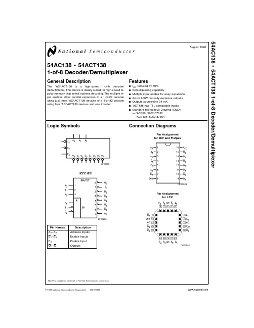
54ACT138中文资料

54AC138•54ACT1381-of-8Decoder/DemultiplexerGeneral DescriptionThe ’AC/’ACT138is a high-speed 1-of-8decoder/demultiplexer.This device is ideally suited for high-speed bi-polar memory chip select address decoding.The multiple in-put enables allow parallel expansion to a 1-of-24decoder using just three ’AC/’ACT138devices or a 1-of-32decoder using four ’AC/’ACT138devices and one inverter.Featuresn I CC reduced by 50%n Demultiplexing capabilityn Multiple input enable for easy expansion n Active LOW mutually exclusive outputs n Outputs source/sink 24mAn ’ACT138has TTL-compatible inputs nStandard Microcircuit Drawing (SMD)—’AC138:5962-87622—’ACT138:5962-87554Logic Symbols Pin Names Description A 0–A 2Address Inputs E 1–E 2Enable Inputs E 3Enable Input O 0–O 7OutputsConnection DiagramsFACT ®is a registered trademark of Fairchild Semiconductor Corporation.DS100268-1IEEE/IECDS100268-7Pin Assignment for DIP and FlatpakDS100268-2Pin Assignmentfor LCCDS100268-3August 199854AC138•54ACT1381-of-8Decoder/Demultiplexer©1998National Semiconductor Corporation Functional DescriptionThe’AC/’ACT138high-speed1-of-8decoder/demultiplexer accepts three binary weighted inputs(A0,A1,A2)and,when enabled,provides eight mutually exclusive active-LOW out-puts(O0–O7).The’AC/’ACT138features three Enable in-puts,two active-LOW(E1,E2)and one active-HIGH(E3).All outputs will be HIGH unless E1and E2are LOW and E3is HIGH.This multiple enable function allows easy parallel ex-pansion of the device to a1-of-32(5lines to32lines)de-coder with just four’AC/’ACT138devices and one inverter (see Figure1).The’AC/’ACT138can be used as an8-output demultiplexer by using one of the active LOW Enable inputs as the data input and the other Enable inputs as strobes.The Enable inputs which are not used must be permanently tied to their appropriate active-HIGH or active-LOW state.Truth TableInputs OutputsE1E2E3A0A1A2O0O1O2O3O4O5O6O7H X X X X X H H H H H H H HX H X X X X H H H H H H H H X X L X X X H H H H H H H HL L H L L L L H H H H H H H L L H H L L H L H H H H H H L L H L H L H H L H H H H H L L H H H L H H H L H H H HL L H L L H H H H H L H H H L L H H L H H H H H H L H H L L H L H H H H H H H H L H L L H H H H H H H H H H H L H=HIGH Voltage LevelL=LOW Voltage LevelX=Immaterial2Logic DiagramDS100268-4Please note that this diagram is provided only for the understanding of logic operations and should not be used to estimate propagation delays.Logic Diagram(Continued)D S 100268-5F IG U R E 1.E x p a n s i o n t o 1-o f -32D e c o d i n g 4Absolute Maximum Ratings(Note1)If Military/Aerospace specified devices are required, please contact the National Semiconductor Sales Office/ Distributors for availability and specifications.Supply Voltage(V CC)−0.5V to+7.0VDC Input Diode Current(I IK) V I=−0.5VV I=V CC+0.5V −20mA +20mADC Input Voltage(V I)−0.5V to V CC+0.5V DC Output Diode Current(I OK)V O=−0.5VV O=V CC+0.5V −20mA +20mADC Output Voltage(V O)−0.5V to V CC+0.5V DC Output Sourceor Sink Current(I O)±50mA DC V CC or Ground Currentper Output Pin(I CC or I GND)±50mA Storage Temperature(T STG)−65˚C to+150˚C Junction Temperature(T J)CDIP175˚C Recommended Operating ConditionsSupply Voltage(V CC)’AC 2.0V to6.0V ’ACT 4.5V to5.5V Input Voltage(V I)0V to V CC Output Voltage(V O)0V to V CC Operating Temperature(T A)54AC/ACT−55˚C to+125˚C Minimum Input Edge Rate(∆V/∆t)’AC DevicesV IN from30%to70%of V CCV CC@3.3V,4.5V,5.5V125mV/ns Minimum Input Edge Rate(∆V/∆t)’ACT DevicesV IN from0.8V to2.0VV CC@4.5V,5.5V125mV/ns Note1:Absolute maximum ratings are those values beyond which damage to the device may occur.The databook specifications should be met,without exception,to ensure that the system design is reliable over its power supply, temperature,and output/input loading variables.National does not recom-mend operation of FACT®circuits outside databook specifications.DC Characteristics for’AC Family Devices54ACSymbol Parameter V CC T A=Units Conditions(V)−55˚C to+125˚CGuaranteed LimitsV IH Minimum HighLevel Input Voltage 3.0 2.1V OUT=0.1V4.5 3.15V or V CC−0.1V5.5 3.85V IL Maximum LowLevel Input Voltage 3.00.9V OUT=0.1V4.5 1.35V or V CC−0.1V5.5 1.65V OH Minimum HighLevel OutputVoltage 3.0 2.9I OUT=−50µA4.5 4.4V5.5 5.4(Note2)V IN=V IL or V IH3.0 2.4−12mA4.5 3.7V I OH−24mA5.5 4.7−24mAV OL Maximum LowLevel OutputVoltage 3.00.1I OUT=50µA4.50.1V5.50.1(Note2)V IN=V IL or V IH3.00.5012mA4.50.50V I OL24mA5.50.5024mAI IN Maximum Input 5.5±1.0µA V I=V CC,GNDLeakage CurrentI OLD(Note3)MinimumDynamic OutputCurrent 5.550mA V OLD=1.65V MaxI OHD 5.5−50mA V OHD=3.85V MinDC Characteristics for’AC Family Devices(Continued)54ACSymbol Parameter V CC T A=Units Conditions(V)−55˚C to+125˚CGuaranteed LimitsI CC MaximumQuiescent Supply Current 5.580.0µAV IN=V CC or GNDNote2:All outputs loaded;thresholds on input associated with output under test.Note3:Maximum test duration2.0ms,one output loaded at a time.Note4:I IN and I CC@3.0V are guaranteed to be less than or equal to the respective limit@5.5V V CC.I CC for54AC@25˚C is identical to74AC@25˚C.DC Characteristics for’ACT Family Devices54ACTSymbol Parameter V CC T A=Units Conditions(V)−55˚C to+125˚CGuaranteed LimitsV IH Minimum HighLevel Input Voltage 4.5 2.0V V OUT=0.1V5.5 2.0or V CC−0.1VV IL Maximum LowLevel Input Voltage 4.50.8V V OUT=0.1V5.50.8or V CC−0.1VV OH Minimum HighLevel OutputVoltage 4.5 4.4V I OUT=−50µA5.5 5.4(Note5)V IN=V IL or V IH4.5 3.70V I OH−24mA5.5 4.70−24mAV OL Maximum LowLevel OutputVoltage 4.50.1V I OUT=50µA5.50.1(Note5)V IN=V IL or V IH4.50.50V I OL24mA5.50.5024mAI IN Maximum Input 5.5±1.0µA V I=V CC,GNDLeakage CurrentI CCT Maximum 5.5 1.6mA V I=V CC−2.1VI CC/InputI OLD(Note6)MinimumDynamic OutputCurrent 5.550mA V OLD=1.65V MaxI OHD 5.5−50mA V OHD=3.85V Min I CC MaximumQuiescent Supply Current 5.580.0µAV IN=V CC or GNDNote5:All outputs loaded;thresholds on input associated with output under test.Note6:Maximum test duration2.0ms,one output loaded at a time.Note7:I CC for54ACT@25˚C is identical to74ACT@25˚C.6AC Electrical Characteristics54ACV CC T A=−55˚C Fig.Symbol Parameter(V)to+125˚C Units No.(Note8)C L=50pFMin Maxt PLH Propagation Delay 3.3 1.016.0nsA n to O n 5.0 1.512.0t PHL Propagation Delay 3.3 1.015.0nsA n to O n 5.0 1.511.5t PLH Propagation Delay 3.3 1.016.5nsE1or E2to O n 5.0 1.513.0t PHL Propagation Delay 3.3 1.015.5nsE1or E2to O n 5.0 1.512.0t PLH Propagation Delay 3.3 1.017.0nsE3to O n 5.0 1.513.5t PHL Propagation Delay 3.3 1.015.0nsE3to O n 5.0 1.511.0Note8:Voltage Range3.3is3.3V±0.3VVoltage Range5.0is5.0V±0.5VAC Electrical Characteristics54ACTV CC T A=−55˚C Fig.Symbol Parameter(V)to+125˚C Units No.(Note9)C L=50pFMin Maxt PLH Propagation Delay 5.0 1.512.5nsA n to O nt PHL Propagation Delay 5.0 1.512.5nsA n to O nt PLH Propagation Delay 5.0 1.513.5nsE1or E2to O nt PHL Propagation Delay 5.0 1.512.5nsE1or E2to O nt PLH Propagation Delay 5.0 1.514.0nsE3to O nt PHL Propagation Delay 5.0 1.512.0nsE3to O nNote9:Voltage Range5.0is5.0V±0.5VCapacitanceSymbol Parameter Typ Units ConditionsC IN Input Capacitance 4.5pF V CC=OPENC PD Power Dissipation60.0pF V CC=5.0VCapacitance8Physical Dimensions inches(millimeters)unless otherwise noted20Terminal Ceramic Leadless Chip Carrier(L)NS Package Number E20A16Lead Ceramic Dual-In-Line Package(D)NS Package Number J16APhysical Dimensions inches(millimeters)unless otherwise noted(Continued)LIFE SUPPORT POLICYNATIONAL’S PRODUCTS ARE NOT AUTHORIZED FOR USE AS CRITICAL COMPONENTS IN LIFE SUPPORT DE-VICES OR SYSTEMS WITHOUT THE EXPRESS WRITTEN APPROVAL OF THE PRESIDENT OF NATIONAL SEMI-CONDUCTOR CORPORATION.As used herein:1.Life support devices or systems are devices or sys-tems which,(a)are intended for surgical implant intothe body,or(b)support or sustain life,and whose fail-ure to perform when properly used in accordancewith instructions for use provided in the labeling,canbe reasonably expected to result in a significant injuryto the user.2.A critical component in any component of a life supportdevice or system whose failure to perform can be rea-sonably expected to cause the failure of the life supportdevice or system,or to affect its safety or effectiveness.National SemiconductorCorporationAmericasTel:1-800-272-9959Fax:1-800-737-7018Email:support@National SemiconductorEuropeFax:+49(0)180-5308586Email:europe.support@Deutsch Tel:+49(0)180-5308585English Tel:+49(0)180-5327832Français Tel:+49(0)180-5329358Italiano Tel:+49(0)180-5341680National SemiconductorAsia Pacific CustomerResponse GroupTel:65-2544466Fax:65-2504466Email:sea.support@National SemiconductorJapan Ltd.Tel:81-3-5620-6175Fax:81-3-5620-617916Lead Ceramic Flatpak(F)NS Package Number W16A54AC138•54ACT1381-of-8Decoder/DemultiplexerNational does not assume any responsibility for use of any circuitry described,no circuit patent licenses are implied and National reserves the right at any time without notice to change said circuitry and specifications.。
BAT54A中文资料

CJ
-
7.6
10
trr
-
-
5.0
Unit Volts Vdc
uAdc pF nS
REV. : 0
Zowie Technology Corporation
Zowie Technology Corporation
BAT54
820
+10 V
2k 100uH IF 0.1uF
FIGURE 1. RECOVERY TIME EQUIVALENT TEST CIRCUIT
Rating Reverse Voltage Forward Power Dissipation @ TA=25oC Derate above 25oC Operating Junction Temperature Range Storage Temperature Range
Symbol VR
PF
2. Input pulse is adjusted so IR(peak) is equal to 10mA. 3. tp » trr
iR(REC) = 1mA
OUTPUT PULSE (IF = I R = 10 mA; measured
at iR(REC) = 1mA
FIGURE 2. FORWARD VOLTAGE
-
0.22
0.24
-
0.29
0.32
VF
-
0.35
0.40
-
0.41
0.50
-
0.52
1.0
Reverse Leakage ( VR=25 Vdc )
IR
-
0.5
2.0
Diode Capacitance ( VR=1.0, f=1.0MHZ )
8508A中文手册

8508A型参考级81/2位数字多用表操作简要说明福禄克公司北京办事处8508A简明操作手册2有限保证和有限责任每台福禄克的产品在正常使用和维护的情况下保证没有材料和工艺上的缺陷。
产品的保证期为一年,从发运 之日起计算。
零件、产品修理和维护的保证期为90天。
此项保证的对象仅为原始购买者或者福禄克授权代理商的最终使用客户,并且不适用于保险丝、普通电池或者福禄克认为由于意外的或不正常的工作或管理状况而错误使用、经过改动、疏忽管理、受到污染或损坏的产品。
福禄克保证软件将按照其功能技术指标牢靠地工作90天,并已经正确地记录在无缺陷的介质上。
福禄克不保证软件没有错误或工作中无中断。
福禄克授权代理商应当只将此种对新的和未使用过的产品的保证延伸到最终使用客户,但无权代表福禄克 做出更高的或不同的保证条件。
只有从福禄克授权的销售渠道购买的产品或者当购买者已经支付了适当的国际价格时才能获得这种保证支持。
当从一个国家购买的产品送到另一个国家进行修理时,福禄克保留向购买者开具修理/更换零件进口费用发票的权利。
福禄克的保证责任是有限的,对于在保证期之内退回到福禄克授权的维修中心的有缺陷的产品, 福禄克可以选择退还购买款项、免费修理或更换产品。
为获得保修,请与您最近的福禄克授权维修中心联系以得到返修授权信息。
然后将该产品发送到该维修 中心,提供故障说明、并付邮资和保险费(FOB目的地)。
福禄克不承担运输中损坏的风险。
保修之后,该产品将返还给购买者,并付运费(FOB目的地)。
如果福禄克认定故障是由于疏忽管理、错误使用、受到污染、经过改动、意外的或不正常的工作或管理状况,包括因超出产品规定的额定值使用而引起的过电压故障,或者正常的磨损和机械部件的破损而引起,福禄克将提供估计的修理费用并在得到授权之后才开始维修工作。
修理之后,该产品将返还给购买者,并付运费。
购买者则要支付修理费用和返程的运输费用(FOB发运点)。
这种保证是购买者唯一的和专有的补救方法,并且可代替所有其它的保证条件、表述或默许的条款,包 括但不限于任何默许的保证条件或者为某种特定目的的商品性或适应性。
54ACT2525FMQB中文资料
54ACT2525FMQB中文资料Original Creation Date: 07/02/96Last Update Date: 03/17/97Last Major Revision Date: 02/05/97MN54ACT2525-X REV 2A0MICROCIRCUIT DATA SHEET1-to-8 Minimum Skew Clock DriverGeneral DescriptionThe ACT2525 is a minimum skew clock driver with one input driving eight outputsspecifically designed for signal generation and clock distribution applications. The 2525is designed to distribute a single clock to eight separate receivers with low skew across all outputs during both the TPLH and TPHL transitions.NS Part Numbers54ACT2525DMQB 54ACT2525FMQB 54ACT2525LMQBIndustry Part Number54ACT2525Prime DieJ2525ProcessingMIL-STD-883, Method 5004Quality Conformance InspectionMIL-STD-883, Method 5005Subgrp Description Temp ( C)o 1Static tests at +252Static tests at +1253Static tests at -554Dynamic tests at +255Dynamic tests at +1256Dynamic tests at -557Functional tests at +258A Functional tests at +1258B Functional tests at -559Switching tests at +2510Switching testsat +12511Switching tests at-55MICROCIRCUIT DATA SHEET MN54ACT2525-X REV 2A0 Features- Ideal for signal generation and clock distribution- Guaranteed pin to pin and part to part skew- Guaranteed 4000V minimum ESD protection- 24mA output drive capability- CT has TTL-compatible inputsMICROCIRCUIT DATA SHEET MN54ACT2525-X REV 2A0 (Absolute Maximum Ratings)(Note 1)Supply Voltage (Vcc)-0.5V to +7.0VDC Input Diode Current (Iik)Vi = -0.5V-20 mAVi = Vcc +0.5V+20 mADC Input Voltage (Vi)-0.5V to Vcc +0.5VDC Output Diode Current (Iok)Vo = -0.5V-20 mAVo = Vcc +0.5V+20 mADC Output Voltage (Vo)-0.5V to Vcc +0.5VDC Output Source or Sink Current (Io)+50 mADC Vcc or Ground Current per Output Pin (Icc or Ignd)+50 mAStorage Temperature (Tstg)-65 C to +150 CJunction Temperature (Tj)CDIP175 CNote 1:Absolute maximum ratings are those values beyond which damage to the device may occur. The databook specifications should be met, without exception, to ensure that the system design is reliable over its power supply, temperature, and output/inputloading variables. National does not recommend operation of CGS circuits outsidedatabook specifications.Recommended Operating ConditionsSupply Voltage (Vcc)4.5V to5.5VInput Voltage (Vi)0V to VccOutput Voltage (Vo)0V to VccOperating Temperature (Ta)-55 C to +125 CMinimum Input Edge Rate (Delta V/Delta t)ACT DevicesVin from 0.8V to 2.0V********,5.5V125 mV/nsMN54ACT2525-X REV 2A0MICROCIRCUIT DATA SHEETElectrical CharacteristicsDC PARAMETERS(The following conditions apply to all the following parameters, unless otherwise specified.)DC:VCC 4.5V to 5.5V, Temperature Range: -55C to 125C. NOTE: -55C TEMPERATURE, SUBGROUP 3 IS GUARANTEED BUT NOT TESTED.SYMBOL PARAMETER CONDITIONS NOTES PIN-NAME MIN MAX UNITSUB-GROUPSIIH High Level InputCurrent VCC=5.5V, VIH=5.5V1, 2INPUT0.1uA11, 2INPUT 1.0uA2, 3IIL Low Level InputCurrent VCC=5.5V, VIL=0.0V1, 2INPUT-0.1uA11, 2INPUT-1.0uA2, 3VOL Low Level OutputVoltage VCC=4.5V, VIH=2.0V, VIL=0.8V,IOL=50.0uA1, 2OUTPUT.10V1, 2,3 VCC=5.5V, VIH=2.0V, VIL=0.8V,IOL=50.0uA1, 2OUTPUT.10V1, 2,3 VCC=4.5V, VIH=2.0V, VIL=0.8V,IOL=24.0mA1, 2OUTPUT.36V11, 2OUTPUT.50V2, 3 VCC=5.5V, VIH=2.0V, VIL=0.8V,IOL=24.0mA1, 2OUTPUT.36V11, 2OUTPUT.50V2, 3VIOL Dynamic outputcurrent Low VCC=5.5V, IOL=50.0mA, VIL=0.0V,VIH=5.5V1,2, 5OUTPUT 1.65V1, 2,3VOH Low Level OutputVoltage VCC=5.5V, IOH=-50.0uA, VIL=0.8V,VIH=2.0V1, 2OUTPUT 5.40V1, 2,3 VCC=4.5V, IOH=-50.0uA, VIL=0.8V,VIH=2.0V1, 2OUTPUT 4.40V1, 2,3 VCC=4.5V, IOH=-24.0mA, VIL=0.8V,VIH=2.0V1, 2OUTPUT 3.86V11, 2OUTPUT 3.70V2, 3 VCC=5.5V, IOH=-24.0mA, VIL=0.8V, VIH=2.0V1, 2OUTPUT 4.86V11, 2OUTPUT 4.70V2, 3VIOH Dynamic outputcurrent High VCC=5.5V, IOH=-50.0mA, VIL=0.0V,VIH=5.5V1,2, 5OUTPUT 3.85V1, 2,3ICCH Supply CurrentOutputs HIGH VCC=5.5V, VIH=5.5V1, 2VCC8.0uA11, 2VCC160uA2, 3ICCL Supply CurrentOutputs LOW VCC=5.5V, VIL=0.0V1, 2VCC8.0uA11, 2VCC160uA2, 3ICCT Supply Currentper Input VCC=5.5V, VINH=3.4V1, 2VCC 1.0mA11, 2VCC 1.6mA2, 3MN54ACT2525-X REV 2A0MICROCIRCUIT DATA SHEETElectrical CharacteristicsAC PARAMETERS(The following conditions apply to all the following parameters, unless otherwise specified.)AC:CL=50pF, RL=500 OHMS, TR/TF=3.0ns, Temp range: -55C to +125C. NOTE: -55C TEMPERATURE, SUBGROUP 11 IS GUARANTEED BUT NOT TESTED.SYMBOL PARAMETER CONDITIONS NOTES PIN-NAME MIN MAX UNITSUB-GROUPStpLH Propagation Delay VCC=4.5V3,4, 7CKIN-On 5.510.0ns93,4, 7CKIN-On7.011.5ns103,4, 7CKIN-On 4.08.5ns11tpHL Propagation Delay VCC=4.5V3,4, 7CKIN-On 1.510.0ns93,4, 7CKIN-On7.011.5ns103,4, 7CKIN-On 4.08.5ns11tosHL Maximum SkewCommon Edge VCC=4.5V6On - On Skew1.0ns9, 10,11tosLH Maximum SkewCommon Edge VCC=4.5V6On - On Skew1.0ns9, 10,11tpV Maximum SkewPart/Part VCC=4.5V6Maximum Skew4.0ns9, 10,11tost Maximum SkewOpposite Edge VCC=4.5V6Maximum Skew1.5ns9, 10,11tR/tF Maximum Rise/FallTime VCC=4.5V6 3.0ns96 4.0ns10, 11Fmax Maximum ClockFrequency VCC=4.5V6CP80Mhz96CP75Mhz10, 11Note 1:SCREEN TESTED 100% ON EACH DEVICE AT +25C & +125C TEMPERATURE, SUBGROUPS 1, 2, 7 & 8. Note 2:SAMPLE TESTED (METHOD 5005, TABLE 1) ON EACH MFG. LOT AT +25C & +125C TEMPERATURE, SUBGROUPS A1, 2, 7 & 8.Note 3:SCREEN TESTED 100% ON EACH DEVICE AT +25C TEMPERATURE ONLY, SUBGROUP A9.Note 4:SAMPLE TESTED (METHOD 5005, TABLE 1) ON EACH MFG. LOT AT +25C & +125C TEMPERATURE, SUBGROUPS A9 & 10.Note 5:TRANSMISSION LINE DRIVING TEST, GUARDBANDED LIMITS SET FOR +25C, 2 MSEC DURATION MAX.Note 6:DESIGN CHARACTERIZATION DATA.Note 7:+25C & +125C MIN LIMITS GUARANTEED FOR 5.5V BY GUARDBANDING 4.5V MINIMUM LIMITS.。
AJ-54C系列控制箱组件清单说明书

SECTION 6: PARTS SECTIONAJ-54 CONTROL BOX ASSEMBLY12345611879101213141516, 1715191820212223AJ-76 & AJ-90 CONTROL BOX ASSEMBLY1 23, 4, 564, 7, 10, 11, 1284, 9, 1014 14 1415 16 17 18 1820, 2122, 23 24, 25, 2626, 2726, 2829 31 303013, 26 19, 26PREWASH PLUMBING ASSEMBLYY-Strainer, 3/4” NPT,Brass04730-717-02-06Nipple, 3/4”, Brass, Close04730-207-34-00Valve, Solenoid, 3/4”04810-100-53-00Nipple, 3/4”, Brass, Close04730-207-34-00Vacuum Breaker, 3/4”04820-002-53-77Elbow, 90°, 3/4” Brass 04730-206-04-34Elbow, 90°, 3/4” Brass 04730-206-04-34Nipple, 3/4” x 6” Long 05700-001-26-74Fill Line Injector Replacement Kit06401-003-09-93A new gasket can be ordered using part num-ber 05330-111-42-81.Replacement Kit Note:The kit for the fill line injector comes with the injector weldment, a new gasket and the mounting hardware.WATER HAMMER ARRESTOR OPTION/WATER PRESSURE REGULATOR KIT OPTIONNipple, 3/4” NPT,Close, Brass 04730-207-34-00Water Arrestor, 1/2” NPT 06685-100-05-00Tee, 3/4” x 3/4” x 1/2”04730-211-06-00Water Arrestor, 1/2” NPT 06685-100-05-00Bushing, 3/4” x 1/2”04730-002-01-34Tee, Brass, 3/4” x 3/4” x 3/4”04730-211-01-34Nipple, Close, 3/4”04730-207-34-00Regulator, Pressure, 3/4”06685-011-58-22WATER PRESSURE REGULATOR WITH ARRESTOR KIT OPTIONWATER HAMMER ARRESTOR OPTIONITEM QTY DESCRIPTIONMfg. No.11Reducer, 3/4” NPT to 1/2” NPT, Black Iron 04730-911-02-3422Union, 3/4” NPT, Black Iron04730-912-01-0034Nipple, Close, 3/4” NPT, Black Iron 04730-907-01-0041Valve, Steam Solenoid, 3/4” NPT, 120V 04820-011-87-3952Elbow, 90°, 3/4” FNPT, Black Iron04730-906-10-3462Elbow, Street, 90°, 3/4” NPT, Black Iron 04730-011-87-3771Y-Strainer, 3/4” NPT, Black Iron 04730-217-01-3281Valve, Gate, Steam, 3/4” NPT 04820-100-19-0091Plug, 3/8” NPT, Black Iron 04730-909-02-34101Nipple, 3/4” NPT x 47” Long04730-021-89-26 111Pipe, 3/4” NPT x 2” Long,Black Iron 04730-907-05-34121Steam Trap, 3/4” NPT06680-500-02-77234105368379156112312STEAM INLET PLUMBINGSTEAM OUTLET PLUMBINGITEM QTY DESCRIPTIONMfg. No.12Reducer, 3/4” NPT to 1/2” NPT, Black Iron 04730-911-02-3422Union, 3/4” NPT, Black Iron04730-912-01-0034Nipple, Close, 3/4” NPT, Black Iron 04730-907-01-0041Valve, Steam Solenoid, 3/4” NPT, 120V 04820-011-87-3951Elbow, 90°, 3/4” FNPT, Black Iron04730-906-10-3461Elbow, Street, 90°, 3/4” NPT, Black Iron 04730-011-87-3771Y-Strainer, 3/4” NPT, Black Iron 04730-217-01-3281Valve, Gate, Steam, 3/4” NPT 04820-100-19-0091Plug, 3/8” NPT, Black Iron 04730-909-02-34101Nipple, 3/4” NPT x 10” Long04730-907-06-34 111Reducer, 3/4” NPT to 1/2” NPT, Black Iron 04730-911-02-34121Elbow, 90°, 3/4” FNPT, Black Iron 04730-906-10-34131Elbow, Street, 3/4” NPT, Black Iron 04730-011-87-37141Steam Trap, 3/4” NPT 06680-500-02-77896371053341213214STEAM INLET PLUMBINGSTEAM OUTLET PLUMBINGTube, Copper, 1-1/2” x 10-1/8” Long05700-002-99-00Adapter, Male to Female, 1-1/2”04730-401-25-01Elbow, 1-1/2” FNPT, 90°, Brass04730-011-73-77Tube, Copper, 1-1/2” x 4-5/8” Long05700-002-98-98Tube, Copper, 1-1/2” x 6-3/8” Long 05700-002-98-99Left to Right Plumbing AssemblyConnector, No-Hub, 1-1/2”4720-604-06-00Valve, Ball, 1-1/2”04820-111-71-46Ball Valve Handle Assembly05700-021-84-74Nipple, Brass, Close, 1-1/2” NPT04730-207-40-00Nipple, Brass, 3” NPT 04730-011-87-04Tee, Brass, 1-1/2” x 1-1/2” x 1-1/2”04730-011-69-93Tube, Copper, 1-1/2” x 6-3/8” Long05700-002-98-99Tube, Copper, 1-1/2” x 4-5/8” Long05700-002-98-98Tube, Copper, 1-1/2” x 10-1/8” Long05700-002-99-00Nipple, Rinse Weldment05700-021-84-61Elbow, Brass,Street, 1-1/2” NPT 04730-206-32-00Right to Left Plumbing AssemblyAll parts are common to both assemblies.MOTOR ASSEMBLIESWASH MOTOR CHART VoltsPhase Hz Motor Part Number Kit Part Number 208 - 23016006105-021-70-5706401-003-09-97200 - 23036006105-121-70-5806401-003-09-9846036006105-121-70-5806401-003-09-9857536006105-002-48-3106401-003-09-9960036006105-002-48-3106401-003-09-99PREWASH MOTOR CHARTModel(s)Volts Phase Hz Part Number Kit Part Number AJ-76’s20816006105-121-70-5506401-003-10-4023016006105-121-70-5506401-003-10-4020036006105-121-70-5606401-003-10-3822036006105-121-70-5606401-003-10-3823036006105-121-70-5606401-003-10-3846036006105-121-70-5606401-003-10-3857536006105-002-48-3106401-003-10-4160036006105-002-48-3106401-003-10-41AJ-90’s20816006105-121-70-5706401-003-10-4223016006105-121-70-5706401-003-10-4220036006105-121-70-5806401-003-10-4322036006105-121-70-5806401-003-10-4323036006105-121-70-5806401-003-10-4346036006105-121-70-5806401-003-10-4357536006105-002-48-3106401-003-10-4160036006105-002-48-3106401-003-10-41See Motor Chart BelowKey, 3/16” x 1” LongPump Plate 05700-021-71-83Cap Screw, 3/8”-16 x 2”05305-011-74-98Wash Impeller Replacement Kit 06401-003-10-51Prewash Impeller Replacement Kit 06401-003-10-55Pump Seal 06401-003-06-73Impeller Washer Bolt, 1/4”-20 x 3/4”Motor Mounting Gasket 06401-003-06-75Replacement Kit Notes:The impeller replacement kits come with the impeller, washer, key and bolt. The motor kits come with everything detailed above as well as two new mounting gaskets.Kit, Motor Brkt Replace 06401-021-73-42Clamp, 4 1/8” - 7” (Not Shown)04730-002-32-15CURTAINS/TUB MAGNETSCurtain, 21” Long x 20-1/2” Wide 08415-131-73-45Curtain, 12” Long x 20-1/2” Wide 08415-131-73-44Curtain Rod05700-021-73-43Long Curtain Decal 09905-011-73-84Short Curtain Decal 09905-011-73-82Curtain, 24 1/2” Long x 20-1/2” Wide CGP MODELS ONLY08415-002-47-37Extra Long Curtain Decal CGP MODELS ONLY09905-002-52-69Middle Curtain Hook05700-011-72-65 Curtain Hook05700-011-83-54Limit Switch Bracket 05700-021-71-18Conveyor Switch Replacement Kit06401-003-11-79Replacement Kit Note:The conveyor switch replacement kitcomes with the switch, a terminal anda wire nut.Service Note:The cord for the conveyor switch needs to be cut to length in the field and have the pink terminal applied there.DRIVE ASSEMBLY(CONTINUED)ITEM QTY DESCRIPTION Mfg. No.11Drive Plate and Rod Weldment05700-021-67-44Replacement Kit with Expansion Legs06401-021-86-80Replacement Kit with Expansion Legs/Adjuster Crank06401-011-94-54 21Adjuster Crank Assembly05700-021-69-95 31Skotch Yoke Weldment Replacement Kit06401-003-08-48 42Coupling & Expansion Leg Weldment05700-021-67-50 51Pawl Bar Drive Linkage Casting09515-021-87-73 61Spacer Plate05700-011-67-58 72Pillow Block Replacement Kit06401-003-08-50 82Shaft Collar05700-011-89-18 91Drive Socket05700-021-67-39 101Drive Plate05700-021-67-42 112Pillow Block03120-021-71-87 121Drive Spring05315-011-83-51 132Shaft Collar05700-011-89-18 141Drive Motor Mounting Bracket05700-031-73-56 151Adjuster Spring05315-011-71-90 161Adjusting Handle Weldment05700-021-72-28 171Drive Motor Replacement KitsDrive Motor (50 Hz Models)06401-003-08-41 1Drive Motor (208-230 Volt, 60 Hz, Single Phase Models)06401-003-08-42Drive Motor (208-230 Volt, 60 Hz, Three Phase Models)06401-003-08-40Drive Motor (600 Volt, 60 Hz, Three Phase Models)06401-003-08-43 181Gear Drive06105-011-87-20 191Roller Bearing03120-011-71-81 201Drive Hub05700-011-67-971920Detail A Front Drive Motor CoverReplacement Kit06401-003-11-64Rear Drive Motor CoverReplacement Kit06401-003-10-18Replacement Kits Notes:The replacement kits for the drive motor covers comewith the weldments and the mounting hardware.PAWL BAR MISCELLANEOUS COMPONENTSPawl Bar Gutter Weldment Replacement Kit06401-003-09-95Bottom Guide BlockTop Guide BlockPawl Bar Gutter Gasket 05330-011-68-55Replacement Kits Notes:The pawl bar gutter weldment replacement kit contains the weld-ment, a gasket and the mounting hardware. The guide block kit con-tains both blocks and a gasket.Service Note:It is highly recommended that when changing out one guide block, that the other be changed out as well, along with the gasket.Guide Block Replacement Kit 06401-003-10-15Pawl Bar Roller Replacement Kit 06401-003-11-80Replacement Kit Notes:The replacement kit for the pawl bar roller comes with the roller, roller shaft, hardware and locknut as shown.Pawl Bar Bracket (with studs) Weldment05700-031-84-68Pawl Bar Bracket (without tabs) Weldment05700-031-92-36Left to Right AssemblyPawl Bar Weldment 05700-031-75-18Pawl Bar Spacer 05700-011-71-45Pawl Bar Dog Casting 05700-021-69-00Pawl Bar Weldment 05700-031-82-00Right to Left AssemblyAJ-76 Complete L-R Assembly 06401-141-81-04AJ-76 Complete R-L Assembly 06401-241-81-04AJ-76 Prison Assembly 06401-341-81-04Left to Right AssemblyBolt, 3/8”-16 x 1-3/4” Long5306-011-36-94Locknut, 3/8”-16 with Nylon Insert 05700-011-72-55Pawl Bar Spacer 05700-011-71-45Pawl Bar Dog Casting05700-021-69-00Pawl Bar Weldment 05700-031-74-19Right to Left AssemblyAll associated hardware, spacers and castings may be ordered using the part numbers indicated in the above assembly.Pawl Bar Weldment 05700-041-82-01Both assemblies contain 20 pawl bar dog castings. Please note the direction of installation as indicated on the above drawings. When replacing pawl bar dog castings, ensure to re-install in the appropriate direction. If you do not, then the rack will not be pulled through the machine during operation.AJ-90 Complete L-R Assembly 06401-141-81-05AJ-90 Complete R-L Assembly 06401-241-81-05AJ-90 Prison Assembly 06401-341-81-05MANIFOLDS/STRAINER SUPPORT WELDMENTSPrewash Manifold Weldment AJ-66 Models Only 05700-031-69-70Prewash Manifold Weldment AJ-80 Models Only 05700-002-24-94Prewash Manifold Weldment (CGP Models Only)05700-002-59-51Wash Manifold Weldment05700-031-71-13Wash Manifold Weldment(CGP Models Only)05700-002-51-14Shoulder Bolt Wingnut Weldment05700-002-46-02Wash Fill Tube Weldment05700-021-71-21Prewash Fill Tube Weldment (AJ-66 & AJ-80 Models Only)05700-021-74-76Vellumoid Gasket 05330-111-42-81Wash Strainer Separator Weldment05700-031-84-38STRAINERSBack Strainer Weldment05700-021-85-11Drain Guard Strainer Weldment 05700-002-09-15Front Strainer Weldment05700-021-85-10Screen Strainer with Handle Weldment 05700-002-09-04Overflow Strainer Support05700-001-96-48Tub Strainer Weldment (CGP Models)05700-002-03-21Wash Intake Strainer Weldment (CGP Models)05700-002-51-52FLOAT SWITCH COMPONENTS/SCRAP BASKETSFloat Switch Support BracketReplacement Kit 06401-003-11-77Float Switch Cover 05700-021-75-71Scrap Basket Lid Weldment05700-002-56-55Scrap Basket Assembly 06401-011-87-78Wash Tank Float Switch Replacement Kit 06401-003-11-75Prewash Tank Float Switch Replacement Kit 06401-003-11-76Replacement Kit Note:The float switch replacement kits contain the float switch with associated terminals, the flat washer and the nut.Service Agent Note:Remember than when reinstalling the float switch that the flat washer goes inside against the tub wall while the nut is on the outside of the tub.Replacement Kit Note:The float switch support bracket replace-ment kit contains the bracket and asso-ciated hardware for mounting.。
SN54ACT7881HV资料
元器件交易网IMPORTANT NOTICETexas Instruments and its subsidiaries (TI) reserve the right to make changes to their products or to discontinueany product or service without notice, and advise customers to obtain the latest version of relevant informationto verify, before placing orders, that information being relied on is current and complete. All products are soldsubject to the terms and conditions of sale supplied at the time of order acknowledgement, including thosepertaining to warranty, patent infringement, and limitation of liability.TI warrants performance of its semiconductor products to the specifications applicable at the time of sale inaccordance with TI’s standard warranty. Testing and other quality control techniques are utilized to the extentTI deems necessary to support this warranty. Specific testing of all parameters of each device is not necessarilyperformed, except those mandated by government requirements.CERTAIN APPLICATIONS USING SEMICONDUCTOR PRODUCTS MAY INVOLVE POTENTIAL RISKS OFDEATH, PERSONAL INJURY, OR SEVERE PROPERTY OR ENVIRONMENTAL DAMAGE (“CRITICALAPPLICATIONS”). TI SEMICONDUCTOR PRODUCTS ARE NOT DESIGNED, AUTHORIZED, ORWARRANTED TO BE SUITABLE FOR USE IN LIFE-SUPPORT DEVICES OR SYSTEMS OR OTHERCRITICAL APPLICATIONS. INCLUSION OF TI PRODUCTS IN SUCH APPLICATIONS IS UNDERSTOOD TOBE FULLY AT THE CUSTOMER’S RISK.In order to minimize risks associated with the customer’s applications, adequate design and operatingsafeguards must be provided by the customer to minimize inherent or procedural hazards.TI assumes no liability for applications assistance or customer product design. TI does not warrant or representthat any license, either express or implied, is granted under any patent right, copyright, mask work right, or otherintellectual property right of TI covering or relating to any combination, machine, or process in which suchsemiconductor products or services might be or are used. TI’s publication of information regarding any thirdparty’s products or services does not constitute TI’s approval, warranty or endorsement thereof.Copyright © 1999, Texas Instruments Incorporated。
BAT54S中文资料_数据手册_参数

Package SOT-23 3L SOT-23 3L SOT-23 3L SOT-23 3L SOT-23 3L SOT-23 3L
Packing Method 3k per Tape and Reel 10k per Tape and Reel 3k per Tape and Reel 3k per Tape and Reel 3k per Tape and Reel 10k per Tape and Reel
PD RJA
Power Dissipation Thermal Resistance, Junction-to-Ambient
Connection Diagram
BAT54 3
BAT54A 3
1
2NC
BAT54C 312BAT54S3121
2
Ordering Information
Part Number BAT54
BAT54_D87Z BAT54A BAT54C BAT54S
BAT54S_D87Z
Top Mark L4P L4P L42 L43 L44 L44
ON Semiconductor and the ON Semiconductor logo are trademarks of Semiconductor Components Industries, LLC dba ON Semiconductor or its subsidiaries in the United States and/or other countries. ON Semiconductor owns the rights to a number of patents, trademarks, copyrights, trade secrets, and other intellectual property. A listing of ON Semiconductor’s product/patent coverage may be accessed at /site/pdf/Patent-Marking.pdf. ON Semiconductor reserves the right to make changes without further notice to any products herein. ON Semiconductor makes no warranty, representation or guarantee regarding the suitability of its products for any particular purpose, nor does ON Semiconductor assume any liability arising out of the application or use of any product or circuit, and specifically disclaims any and all liability, including without limitation special, consequential or incidental damages. Buyer is responsible for its products and applications using ON Semiconductor products, including compliance with all laws, regulations and safety requirements or standards, regardless of any support or applications information provided by ON Semiconductor. “Typical” parameters which may be provided in ON Semiconductor data sheets and/or specifications can and do vary in different applications and actual performance may vary over time. All operating parameters, including “Typicals” must be validated for each customer application by customer’s technical experts. ON Semiconductor does not convey any license under its patent rights nor the rights of others. ON Semiconductor products are not designed, intended, or authorized for use as a critical component in life support systems or any FDA Class 3 medical devices or medical devices with a same or similar classification in a foreign jurisdiction or any devices intended for implantation in the human body. Should Buyer purchase or use ON Semiconductor products for any such unintended or unauthorized application, Buyer shall indemnify and hold ON Semiconductor and its officers, employees, subsidiaries, affiliates, and distributors harmless against all claims, costs, damages, and expenses, and reasonable attorney fees arising out of, directly or indirectly, any claim of personal injury or death associated with such unintended or unauthorized use, even if such claim alleges that ON Semiconductor was negligent regarding the design or manufacture of the part. ON Semiconductor is an Equal Opportunity/Affirmative Action Employer. This literature is subject to all applicable copyright laws and is not for resale in any manner.
54LS08中文资料

TL F 634754LS08 DM54LS08 DM74LS08 Quad 2-Input AND GatesJune198954LS08 DM54LS08 DM74LS08Quad2-Input AND Gates General DescriptionThis device contains four independent gates each of whichperforms the logic AND functionFeaturesY Alternate Military Aerospace device(54LS08)is avail-able Contact a National Semiconductor Sales OfficeDistributor for specificationsConnection DiagramDual-In-Line PackageTL F 6347–1 Order Number54LS08DMQB 54LS08FMQB 54LS08LMQB DM54LS08J DM54LS08W DM74LS08M or DM74LS08NSee NS Package Number E20A J14A M14A N14A or W14BFunction TableY e ABInputs OutputA B YL L LL H LH L LH H HH e High Logic LevelL e Low Logic LevelC1995National Semiconductor Corporation RRD-B30M105 Printed in U S AAbsolute Maximum Ratings(Note)If Military Aerospace specified devices are required please contact the National Semiconductor Sales Office Distributors for availability and specifications Supply Voltage7V Input Voltage7V Operating Free Air Temperature RangeDM54LS and54LS b55 C to a125 C DM74LS0 C to a70 C Storage Temperature Range b65 C to a150 C Note The‘‘Absolute Maximum Ratings’’are those values beyond which the safety of the device cannot be guaran-teed The device should not be operated at these limits The parametric values defined in the‘‘Electrical Characteristics’’table are not guaranteed at the absolute maximum ratings The‘‘Recommended Operating Conditions’’table will define the conditions for actual device operationRecommended Operating ConditionsSymbol ParameterDM54LS08DM74LS08Units Min Nom Max Min Nom MaxV CC Supply Voltage4 555 54 7555 25V V IH High Level Input Voltage22V V IL Low Level Input Voltage0 70 8V I OH High Level Output Current b0 4b0 4mA I OL Low Level Output Current48mA T A Free Air Operating Temperature b55125070 C Electrical Characteristics over recommended operating free air temperature range(unless otherwise noted)Symbol Parameter Conditions MinTypMax Units (Note1)V I Input Clamp Voltage V CC e Min I I e b18mA b1 5V V OH High Level Output V CC e Min I OH e Max DM542 53 4V Voltage V IH e Min DM742 73 4V OL Low Level Output V CC e Min I OL e Max DM540 250 4 Voltage V IL e Max DM740 350 5VI OL e4mA V CC e Min DM740 250 4I I Input Current Max V CC e Max V I e7V0 1mAInput VoltageI IH High Level Input Current V CC e Max V I e2 7V20m A I IL Low Level Input Current V CC e Max V I e0 4V b0 36mAI OS Short Circuit V CC e Max DM54b20b100mA Output Current(Note2)DM74b20b100I CCH Supply Current with V CC e Max2 44 8mAOutputs HighI CCL Supply Current with V CC e Max4 48 8mAOutputs LowSwitching Characteristics at V CC e5V and T A e25 C(See Section1for Test Waveforms and Output Load)R L e2k XSymbol Parameter C L e15pF C L e50pF UnitsMin Max Min Maxt PLH Propagation Delay Time413618ns Low to High Level Outputt PHL Propagation Delay Time311518ns High to Low Level OutputNote1 All typicals are at V CC e5V T A e25 CNote2 Not more than one output should be shorted at a time and the duration should not exceed one second23Physical Dimensions inches(millimeters)Ceramic Leadless Chip Carrier Package(E)Order Number54LS08LMQBNS Package Number E20A14-Lead Ceramic Dual-In-Line Package(J)Order Number54LS08DMQB or DM54LS08JNS Package Number J14A4Physical Dimensions inches(millimeters)(Continued)14-Lead Small Outline Molded Package(M)Order Number DM74LS08MNS Package Number M14A14-Lead Molded Dual-In-Line Package(N)Order Number DM74LS08NNS Package Number N14A554L S 08 D M 54L S 08 D M 74L S 08Q u a d 2-I n p u t A N D G a t e sPhysical Dimensions inches (millimeters)(Continued)14-Lead Ceramic Flat Package (W)Order Number 54LS08FMQB or DM54LS08WNS Package Number W14BLIFE SUPPORT POLICYNATIONAL’S PRODUCTS ARE NOT AUTHORIZED FOR USE AS CRITICAL COMPONENTS IN LIFE SUPPORT DEVICES OR SYSTEMS WITHOUT THE EXPRESS WRITTEN APPROVAL OF THE PRESIDENT OF NATIONAL SEMICONDUCTOR CORPORATION As used herein 1 Life support devices or systems are devices or 2 A critical component is any component of a life systems which (a)are intended for surgical implant support device or system whose failure to perform can into the body or (b)support or sustain life and whose be reasonably expected to cause the failure of the life failure to perform when properly used in accordance support device or system or to affect its safety or with instructions for use provided in the labeling can effectivenessbe reasonably expected to result in a significant injury to the userNational Semiconductor National Semiconductor National Semiconductor National Semiconductor CorporationEuropeHong Kong LtdJapan Ltd1111West Bardin RoadFax (a 49)0-180-530858613th Floor Straight Block Tel 81-043-299-2309。
54AC138中文资料
−0.5V to +7.0V
−20 mA +20 mA −0.5V to VCC + 0.5V
−20 mA +20 mA −0.5V to VCC + 0.5V
±50 mA
±50 mA −65˚C to +150˚C
175˚C
Conditions
Supply Voltage (VCC) ’AC
2.0V to 6.0V
125 mV/ns
Note 1: Absolute maximum ratings are those values beyond which damage
to the device may occur. The databook specifications should be met, without
exception, to ensure that the system design is reliable over its power supply,
temperature, and output/input loading variables. National does not recom-
— ’AC138: 5962-87622 — ’ACT138: 5962-87554
Logic Symbols
Connection Diagrams
Pin Assignment for DIP and Flatpak
IEEE/IEC
DS100268-1
Pin Names A0– A2 E1– E2 E3 O0– O7
L
H = HIGH Voltage Level L = LOW Voltage Level X = Immaterial
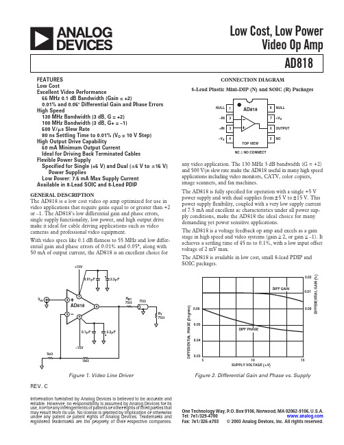
ANALOG DEVICES - AD818 数据手册
± 15 V ±5 V ± 15 V 0 V, +5 V ±5 V ± 15 V ±5 V ± 15 V ± 15 V ± 15 V ±5 V 0 V, +5 V ± 15 V ±5 V 0 V, +5 V
TMIN to TMAX
TMIN TMAX
TMIN to TMAX
VOUT = ± 2.5 V RLOAD = 500 W TMIN to TMAX RLOAD = 150 W VOUT = ± 10 V RLOAD = 1 kW TMIN to TMAX VOUT = ± 7.5 V RLOAD = 150 W (50 mA Output) VCM = ± 2.5 V VCM = ± 12 V TMIN to TMAX
The AD818 is a voltage feedback op amp and excels as a gain stage in high speed and video systems (gain ≥ 2, or gain £ –1). It achieves a settling time of 45 ns to 0.1%, with a low input offset voltage of 2 mV max.
± 5 V to ± 15 V ± 5 V, ± 15 V ± 5 V, ± 15 V ±5 V ± 15 V ± 15 V ±5 V ± 15 V ± 15 V
AD818A
Min
Typ Max
70
95
100
130
40
55
50
70
70
100
30
50
20
43
40
55
Rate Card 54 - 亚洲电视
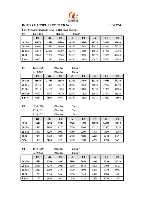
HOME CHANNEL RATE CARD 54 H-RC54 Basic Spot Announcement Rates (in Hong Kong Dollars)C7 1755-2305 (Monday - Sunday)RB FB F1 F2 F3 F4 F5 F6 30-Sec 30070 34580 41500 49800 59760 68720 79030 90880 20-Sec 24060 27670 33200 39840 47810 54980 63230 72720 15-Sec 19550 22480 26980 32370 38850 44680 51380 59090 10-Sec 15040 17300 20760 24910 29890 34370 39530 45460 5-Sec 9920 11410 13690 16430 19710 22670 26070 29980C5 1225-1320 (Monday - Sunday)2310-2405 (Monday - Sunday)RB FB F1 F2 F3 F4 F5 F6 30-Sec 18940 21780 26140 31360 37640 43280 49780 57240 20-Sec 15150 17420 20910 25090 30110 34620 39820 45790 15-Sec 12310 14160 16990 20390 24460 28130 32350 37200 10-Sec 9470 10890 13070 15680 18820 21640 24890 28620 5-Sec 6250 7190 8630 10350 12420 14280 16430 18890C3 0630-1220 (Monday - Sunday)1325-1605 (Monday - Sunday)2410-2605 (Monday - Sunday)RB FB F1 F2 F3 F4 F5 F6 30-Sec 5640 6490 7780 9340 11210 12890 14820 17050 20-Sec 4510 5190 6220 7470 8960 10310 11850 13630 15-Sec 3670 4220 5060 6080 7290 8390 9650 11090 10-Sec 2820 3240 3890 4670 5600 6440 7410 8520 5-Sec 1860 2140 2570 3080 3700 4250 4890 5620C1 1610-1750 (Monday - Sunday)0210-0625 (Monday - Sunday)RB FB F1 F2 F3 F4 F5 F6 30-Sec 3550 4080 4900 5880 7050 8110 9330 10730 20-Sec 2840 3270 3920 4700 5640 6490 7460 8580 15-Sec 2310 2660 3190 3830 4590 5280 6070 6980 10-Sec 1780 2050 2460 2950 3540 4070 4680 5380 5-Sec 1170 1350 1610 1940 2330 2670 3070 3540WORLD CHANNEL RATE CARD 54 W-RC54 Basic Spot Announcement Rates (in Hong Kong Dollars)E5 2055-2355 (Monday - Sunday)RB FB F1 F2 F3 F4 F5 F6 30-Sec 6720 7730 9270 11130 13350 15360 17660 20310 20-Sec 5380 6190 7420 8910 10690 12290 14140 16260 15-Sec 4370 5030 6030 7240 8680 9990 11480 13210 10-Sec 3360 3860 4640 5560 6680 7680 8830 10150 5-Sec 2220 2550 3060 3680 4410 5070 5830 6710E4 1855-2050 (Monday - Sunday)RB FB F1 F2 F3 F4 F5 F6 30-Sec 4370 5030 6030 7240 8680 9990 11480 13210 20-Sec 3500 4030 4830 5800 6960 8000 9200 10580 15-Sec 2840 3270 3920 4700 5640 6490 7460 8580 10-Sec 2190 2520 3020 3630 4350 5000 5760 6620 5-Sec 1440 1660 1990 2380 2860 3290 3780 4350E3Station Opening - 0755 (Monday - Sunday)2400 - Station Closing (Monday - Sunday)RB FB F1 F2 F3 F4 F5 F6 30-Sec 2490 2860 3440 4120 4950 5690 6540 7530 20-Sec 1990 2290 2750 3300 3950 4550 5230 6010 15-Sec 1620 1860 2240 2680 3220 3700 4260 4900 10-Sec 1250 1440 1730 2070 2480 2860 3290 3780 5-Sec 820 940 1130 1360 1630 1870 2160 2480E1 0800-1850 (Monday - Sunday)RB FB F1 F2 F3 F4 F5 F6 30-Sec 1350 1550 1860 2240 2680 3090 3550 4080 20-Sec 1080 1240 1490 1790 2150 2470 2840 3260 15-Sec 880 1010 1210 1460 1750 2010 2310 2660 10-Sec 680 780 940 1130 1350 1550 1790 2060 5-Sec 450 520 620 750 890 1030 1180 1360*In the event of continuous transmission, a broadcasting day commences at 0600 for the following 24 hoursASIA CHANNEL RATE CARD 54 A-RC54 Basic Spot Announcement Rates (in Hong Kong Dollars)A3 0925-1800 (Monday - Sunday)2125-2600 (Monday - Sunday)RB FB F1 F2 F3 F4 F5 F6 30-Sec 2160 2480 2980 3580 4290 4940 5680 6530 20-Sec 1730 1990 2390 2860 3440 3950 4550 5230 15-Sec 1400 1610 1930 2320 2780 3200 3680 4230 10-Sec 1080 1240 1490 1790 2150 2470 2840 3260 5-Sec 710 820 980 1180 1410 1620 1870 2150 A2 0600-0920 (Monday - Sunday)1805-2120 (Monday - Sunday)RB FB F1 F2 F3 F4 F5 F6 30-Sec 1520 1750 2100 2520 3020 3470 3990 4590 20-Sec 1220 1400 1680 2020 2420 2790 3210 3690 15-Sec 990 1140 1370 1640 1970 2260 2600 2990 10-Sec 760 870 1050 1260 1510 1740 2000 2300 5-Sec 500 580 690 830 990 1140 1310 1510 A1 2605-0555 (Monday - Sunday)RB FB F1 F2 F3 F4 F5 F6 30-Sec 790 910 1090 1310 1570 1810 2080 2390 20-Sec 630 720 870 1040 1250 1440 1660 1900 15-Sec 510 590 700 840 1010 1170 1340 1540 10-Sec 400 460 550 660 790 910 1050 12105-Sec 260 300 360 430 520 590 680 790HOME CHANNEL RATE CARD 54M H-RC54M Basic Spot Announcement Rates (in Hong Kong Dollars)C7 1755-2305 (Monday - Sunday)RB FB F1 F2 F3 F4 F5 F630-Sec 23130 26600 31920 38300 45960 52860 60790 6991020-Sec 18500 21280 25530 30640 36760 42280 48620 5591015-Sec 15030 17280 20740 24890 29870 34350 39500 4542010-Sec 11570 13310 15970 19160 22990 26440 30410 349705-Sec 7630 8770 10530 12640 15160 17440 20050 23060C5 1225-1320 (Monday - Sunday)2310-2405 (Monday - Sunday)RB FB F1 F2 F3 F4 F5 F630-Sec 14570 16760 20110 24130 28950 33300 38290 4403020-Sec 11660 13410 16090 19310 23170 26650 30640 3524015-Sec 9470 10890 13070 15680 18820 21640 24890 2862010-Sec 7290 8380 10060 12070 14490 16660 19160 220305-Sec 4810 5530 6640 7970 9560 10990 12640 14540HOME CHANNEL RATE CARD 54M H-RC54M Basic Spot Announcement Rates (in Hong Kong Dollars)C3 0630-1220 (Monday - Sunday)1325-1605 (Monday - Sunday)2410-2605 (Monday - Sunday)RB FB F1 F2 F3 F4 F5 F630-Sec 4340 4990 5990 7190 8620 9920 11410 1312020-Sec 3470 3990 4790 5750 6900 7930 9120 1049015-Sec 2820 3240 3890 4670 5600 6440 7410 852010-Sec 2170 2500 2990 3590 4310 4960 5700 65605-Sec 1430 1640 1970 2370 2840 3270 3760 4320C1 1610-1750 (Monday - Sunday)0210-0625 (Monday - Sunday)RB FB F1 F2 F3 F4 F5 F630-Sec 2730 3140 3770 4520 5430 6240 7170 825020-Sec 2180 2510 3010 3610 4330 4980 5730 659015-Sec 1770 2040 2440 2930 3520 4040 4650 535010-Sec 1370 1580 1890 2270 2720 3130 3600 41405-Sec 900 1040 1240 1490 1790 2060 2370 27202WORLD CHANNEL RATE CARD 54MW-RC54M Basic Spot Announcement Rates (in Hong Kong Dollars)E5 2055-2355 (Monday - Sunday)RB FB F1 F2 F3 F4 F5 F630-Sec 4170 4800 5750 6910 8290 9530 10960 1260020-Sec 3340 3840 4610 5530 6640 7630 8780 1009015-Sec 2710 3120 3740 4490 5390 6190 7120 819010-Sec 2090 2400 2880 3460 4150 4780 5490 63205-Sec 1380 1590 1900 2290 2740 3150 3630 4170E4 1855-2050 (Monday - Sunday)RB FB F1 F2 F3 F4 F5 F630-Sec 2710 3120 3740 4490 5390 6190 7120 819020-Sec 2170 2500 2990 3590 4310 4960 5700 656015-Sec 1760 2020 2430 2910 3500 4020 4630 532010-Sec 1360 1560 1880 2250 2700 3110 3570 41105-Sec 890 1020 1230 1470 1770 2030 2340 26903WORLD CHANNEL RATE CARD 54MW-RC54M Basic Spot Announcement Rates (in Hong Kong Dollars)E3 Station Opening - 0755 (Monday - Sunday)2400 - Station Closing (Monday - Sunday)RB FB F1 F2 F3 F4 F5 F630-Sec 1540 1770 2130 2550 3060 3520 4050 465020-Sec 1230 1410 1700 2040 2440 2810 3230 372015-Sec 1000 1150 1380 1660 1990 2290 2630 302010-Sec 770 890 1060 1280 1530 1760 2020 23305-Sec 510 590 700 840 1010 1170 1340 1540E1 0800-1850 (Monday - Sunday)RB FB F1 F2 F3 F4 F5 F630-Sec 840 970 1160 1390 1670 1920 2210 254020-Sec 670 770 920 1110 1330 1530 1760 202015-Sec 550 630 760 910 1090 1260 1450 166010-Sec 420 480 580 700 830 960 1100 12705-Sec 280 320 390 460 560 640 740 850*In the event of continuous transmission, a broadcasting day commences at 0600 for the following 24 hours.4ASIA CHANNEL RATE CARD 54MA-RC54M Basic Spot Announcement Rates (in Hong Kong Dollars)A3 0925-1800 (Monday - Sunday)2125-2600 (Monday - Sunday)RB FB F1 F2 F3 F4 F5 F630-Sec 1660 1910 2290 2750 3300 3790 4360 502020-Sec 1330 1530 1840 2200 2640 3040 3500 402015-Sec 1080 1240 1490 1790 2150 2470 2840 326010-Sec 830 950 1150 1370 1650 1900 2180 25105-Sec 550 630 760 910 1090 1260 1450 1660A2 0600-0920 (Monday - Sunday)1805-2120 (Monday - Sunday)RB FB F1 F2 F3 F4 F5 F630-Sec 1170 1350 1610 1940 2330 2670 3070 354020-Sec 940 1080 1300 1560 1870 2150 2470 284015-Sec 760 870 1050 1260 1510 1740 2000 230010-Sec 590 680 810 980 1170 1350 1550 17805-Sec 390 450 540 650 780 890 1020 11805ASIA CHANNEL RATE CARD 54MA-RC54M Basic Spot Announcement Rates (in Hong Kong Dollars)A1 2605-0555 (Monday - Sunday)RB FB F1 F2 F3 F4 F5 F630-Sec 610 700 840 1010 1210 1390 1600 184020-Sec 490 560 680 810 970 1120 1290 148015-Sec 400 460 550 660 790 910 1050 121010-Sec 310 360 430 510 620 710 810 9405-Sec 200 230 280 330 400 460 530 6006。
- 1、下载文档前请自行甄别文档内容的完整性,平台不提供额外的编辑、内容补充、找答案等附加服务。
- 2、"仅部分预览"的文档,不可在线预览部分如存在完整性等问题,可反馈申请退款(可完整预览的文档不适用该条件!)。
- 3、如文档侵犯您的权益,请联系客服反馈,我们会尽快为您处理(人工客服工作时间:9:00-18:30)。
54ACT8188-Bit Diagnostic RegisterGeneral DescriptionThe ’ACT818is a high-speed,general-purpose pipeline reg-ister with an on-board diagnostic register for performing se-rial diagnostics and/or writable control store loading.The D-to-Y path provides an 8-bit parallel data path pipeline register for normal system operation.The diagnostic register can load parallel data to or from the pipeline register and can output data through the D input port (as in WCS loading).The 8-bit diagnostic register has multiplexer inputs that se-lect parallel inputs from the Y-port or adjacent bits in the di-agnostic register to operate as a right-shift-only register.This register can then participate in a serial loop throughout the system where normal data,address,status and control reg-isters are replaced with ’ACT818diagnostic pipeline regis-ters.The loop can be used to scan in a complete test routine starting point (Data,Address,etc.).Then after a specified number of machine cycles it scans out the results to be in-spected for the expected results.WCS loading can be ac-complished using the same technique.An instruction word can be serially shifted into the shadow register and written into the WCS RAM by enabling the D output.Featuresn On-line and off-line system diagnosticsn Swaps the contents of diagnostic register and output registern Diagnostic register and diagnostic testingn Cascadable for wide control words as used in microprogrammingn Edge-triggered D registers n Outputs source/sink 24mAn ’ACT818has TTL-compatible inputsn ’ACT818is functionally-and pin-compatible to AMD Am29818and MMI 74S818n Standard Microcircuit Drawing (SMD)5962-9160901Applicationsn Register for microprogram control store n Status register n Data registern Instruction register n Interrupt mask register n Pipeline registern General purpose registernParallel-serial/serial-parallel converterLogic SymbolTRI-STATE ®is a registered trademark of National Semiconductor Corporation.FACT ™is a trademark of Fairchild Semiconductor Corporation.DS100251-3September 199854ACT8188-Bit Diagnostic Register©1998National Semiconductor Corporation Connection DiagramsPin Names DescriptionD 0–D 7Data Inputs SDI Serial Data Input DCLK Diagnostics Clock MODE Control InputPCLK Pipeline Register Clock OEY Output Enable Input SDO Serial Data Output Y 0–Y 7Data OutputsDiagnostic RegisterPin Assignment for DIP and FlatpakDS100251-1Pin Assignmentfor LCCDS100251-2DS100251-4 2Block Diagram Functional DescriptionData transfers into the diagnostic register occur on the LOW-to-HIGH transition of DCLK.Mode and SDI determine what data source will be loaded.The pipeline register is loaded on the LOW-to-HIGH transition of PCLK.Mode se-lects whether the data source is the data input or the diag-nostic register output.Because of the independence of the clock inputs,data can be shifted in the diagnostic register via DCLK and loaded into the pipeline register from the data in-put via PCLK simultaneously,as long as no setup or hold times are violated.This simultaneous operation is legal.Function TableInputs Outputs OperationSDI MODE DCLK PCLK SDO Diagnostic Reg.Pipeline Reg.X L N X S7SI<SI−1,NA Serial Shift;D7–D0DisabledSO<SD IX L X N S7NA PI<DI Normal Load Pipeline RegisterL H N X L SI<YI NA Load Diagnostic Register from Y;DI DisabledX H X N SDI NA PI<SI Load Pipeline Register fromDiagnostic RegisterH H N X H Hold NA Hold Diagnostic Register;DIEnabledH=HIGH Voltage LevelL=LOW Voltage LevelX=ImmaterialN=LOW-to-HIGH Clock TransitionDS100251-53Absolute Maximum Ratings(Note1)If Military/Aerospace specified devices are required, please contact the National Semiconductor Sales Office/ Distributors for availability and specifications.Supply Voltage(V CC)−0.5V to+7.0V DC Input Diode Current(I IK)V I=−0.5V−20mA V I=V CC+0.5V+20mA DC Input Voltage(V I)−0.5V to V CC+0.5V DC Output Diode Current(I OK)V O=−0.5V−20mA V O=V CC+0.5V+20mA DC Output Voltage(V O)−0.5V to V CC+0.5V DC Output Sourceor Sink Current(I O)±50mA DC V CC or Ground Currentper Output Pin(I CC or I GND)±50mA Storage Temperature(T STG)−65˚C to+150˚C Junction Temperature(T J)CDIP175˚C Recommended Operating ConditionsSupply Voltage(V CC)’ACT 4.5V to5.5V Input Voltage(V I)0V to V CC Output Voltage(V O)0V to V CC Operating Temperature(T A)54ACT−55˚C to+125˚C Minimum Input Edge Rate(∆V/∆t)’ACT DevicesV IN from0.8V to2.0VV CC@4.5V,5.5V125mV/ns Note1:Absolute maximum ratings are those values beyond which damage to the device may occur.The databook specifications should be met,without exception,to ensure that the system design is reliable over its power supply, temperature,and output/input loading variables.National does not recom-mend operation of FACT™circuits outside databook specifications.Note2:All outputs loaded;thresholds on input associated with output under test.DC Characteristics for’ACT Family Devices54ACTSymbol Parameter V CC T A=Units Conditions(V)−55˚C to+125˚CGuaranteed LimitsV IH Minimum High Level 4.5 2.0V V OUT=0.1V Input Voltage 5.5 2.0or V CC−0.1V V IL Maximum Low Level 4.50.8V OUT=0.1V Input Voltage 5.50.8or V CC−0.1VI IN Maximum Input 5.5±1.0µA V IN=V CCLeakage CurrentI OZ Maximum TRI-STATE 5.5±1.0µA OE=V IHLeakage Current V OUT=0V,V CCI CC Maximum Quiescent 5.5160µA V IN=V CC or GNDSupply CurrentI CCT Maximum Additional 5.5 1.6mA V IN=V CC−2.1VI CC/Input V CC=5.5VV OH Minimum HIGH(Note2)V IN=V IL or V IH Level Output Voltage, 4.5 3.70V I OH=−24mAY0–Y7Outputs 5.5 4.70V I OH=−24mAMinimum HIGHLevel Output Voltage, 4.5 3.70V I OH=−8mAD0–D7,SDO Outputs 5.5 4.70V I OH=−8mA V OL Maximum LOW(Note2)V IN=V IL or V IH Level Output Voltage, 4.50.50V I OL=24mAY0–Y7Outputs 5.50.50V I OL=24mAMaximum LOWLevel Output Voltage, 4.50.50V I OL=8mAD0–D7,SDO Outputs 5.50.50V I OL=8mA4DC Characteristics for’ACT Family Devices(Continued)54ACTSymbol Parameter V CC T A=Units Conditions(V)−55˚C to+125˚CGuaranteed LimitsI OLD Minimum Dynamic V OLD=1.65V MaxOutput Current, 5.550mAY0–Y7OutputsI OHD Minimum Dynamic V OHD=3.85V MinOutput Current, 5.5−50mAY0–Y7OutputsI OLD Minimum Dynamic V OLD=1.65V MaxOutput Current, 5.532mAD0–D7,SDO Outputs(Note4)I OHD Minimum Dynamic V OHD=3.85V MinOutput Current, 5.5−32mAD0–D7,SDO Outputs(Note4)Note3:Maximum test duration2.0ms,one output loaded at a time.Note4:Test load50pF,500Ωto ground.Note5:I CC for54ACT@25˚C is identical to74ACT@25˚C.AC Electrical Characteristics54ACTV CC T A=−55˚C Fig. Symbol Parameter(V)to+125˚C Units No.(Note6)C L=50pFMin Maxt PHL Propagation Delay 5.0 2.510.0nsPCLK to Yt PLH Propagation Delay 5.0 2.510.0nsPCLK to Yt PHL Propagation Delay 5.0 3.512.0nsMODE to SDOt PLH Propagation Delay 5.0 3.513.5nsMODE to SDOt PHL Propagation Delay 5.0 3.011.5nsSDI to SDOt PLH Propagation Delay 5.0 3.012.0nsSDI to SDOt PHL Propagation Delay 5.0 3.514.0nsDCLK to SDOt PLH Propagation Delay 5.0 3.515.5nsDCLK to SDOt PZL Output Enable Time 5.0 2.512.0nsOEY to Y nt PLZ Output Disable Time 5.0 1.510.0nsOEY to Y nt PZL Output Enable Time 5.0 3.014.0nsDCLK to D n5AC Electrical Characteristics(Continued)54ACTV CC T A=−55˚C Fig.Symbol Parameter(V)to+125˚C Units No.(Note6)C L=50pFMin Maxt PLZ Output Disable Time 5.0 1.512.0ns DCLK to D nt PZH Output Enable Time 5.0 2.511.0ns OEY to Y nt PHZ Output Disable Time 5.0 2.012.0ns OEY to Y nt PZH Output Enable Time 5.0 3.013.5ns DCLK to D nt PHZ Output Disable Time 5.0 2.013.5ns DCLK to D nNote6:Voltage Range5.0is5.0V±0.5V.AC Operating Requirements54ACTV CC T A=−55˚C Fig.Symbol Parameter(V)to+125˚C Units No.(Note8)C L=50pFGuaranteed Minimumt s Setup Time 5.0 6.0nsD to PCLKt h Hold Time 5.0 1.0nsD to PCLKt s Setup Time 5.0 6.0nsMODE to PCLKt h Hold Time 5.00.0nsMODE to PCLKt s Setup Time 5.0 2.5nsY to DCLKt h Hold Time 5.0 1.5nsY to DCLKt s Setup Time 5.0 4.5nsMODE to DCLKt h Hold Time 5.0 1.0nsMODE to DCLKt s Setup Time 5.0 4.5nsSDI to DCLKt h Hold Time 5.0 1.0nsSDI to DCLKt s Setup Time 5.011.5nsDCLK to PCLKt s Setup Time 5.012.5nsPCLK to DCLKt w Pulse Width 5.0 3.5ns6AC Operating Requirements(Continued)54ACTV CC T A=−55˚C Fig.Symbol Parameter(V)to+125˚C Units No.(Note8)C L=50pFGuaranteed MinimumPCLK HIGH orLOWt w Pulse Width 5.0 3.0nsDCLK HIGH orLOWNote7:Test load50pF,500Ωto ground.Note8:Voltage range5.0is5.0V±0.5V.CapacitanceSymbol Parameter Typ Units ConditionsC IN Input Capacitance 4.5pF V CC=OPENC PD Power Dissipation20pF V CC=5.0VCapacitance78Physical Dimensions inches(millimeters)unless otherwise noted28Terminal Ceramic Leadless Chip Carrier(L)NS Package Number E28A24Lead Slim(0.300"wide)Ceramic Dual-in-Line Package(D)NS Package Number J24F9Physical Dimensions inches(millimeters)unless otherwise noted(Continued)LIFE SUPPORT POLICYNATIONAL’S PRODUCTS ARE NOT AUTHORIZED FOR USE AS CRITICAL COMPONENTS IN LIFE SUPPORT DE-VICES OR SYSTEMS WITHOUT THE EXPRESS WRITTEN APPROVAL OF THE PRESIDENT OF NATIONAL SEMI-CONDUCTOR CORPORATION.As used herein:1.Life support devices or systems are devices or sys-tems which,(a)are intended for surgical implant intothe body,or(b)support or sustain life,and whose fail-ure to perform when properly used in accordancewith instructions for use provided in the labeling,canbe reasonably expected to result in a significant injuryto the user.2.A critical component in any component of a life supportdevice or system whose failure to perform can be rea-sonably expected to cause the failure of the life supportdevice or system,or to affect its safety or effectiveness.National SemiconductorCorporationAmericasTel:1-800-272-9959Fax:1-800-737-7018Email:support@National SemiconductorEuropeFax:+49(0)180-5308586Email:europe.support@Deutsch Tel:+49(0)180-5308585English Tel:+49(0)180-5327832Français Tel:+49(0)180-5329358Italiano Tel:+49(0)180-5341680National SemiconductorAsia Pacific CustomerResponse GroupTel:65-2544466Fax:65-2504466Email:sea.support@National SemiconductorJapan Ltd.Tel:81-3-5620-6175Fax:81-3-5620-617924Lead Ceramic CerpackNS Package Number W24C54ACT8188-BitDiagnosticRegisterNational does not assume any responsibility for use of any circuitry described,no circuit patent licenses are implied and National reserves the right at any time without notice to change said circuitry and specifications.。