Latke 快速上手指南
Lattice编程电缆用户指南说明书

Programming CablesUser’s GuideFeatures•Support for all Lattice programmable products–1.2 V to 3.3 V programming (HW-USBN-2B)–1.2 V to 5 V programming (All other cables)–Ideal for design prototyping and debugging•Connect to multiple PC interfaces–USB (v.1.0, v.2.0)–PC Parallel Port•Easy-to-use programming connectors•Versatile flywire, 2 x 5 (.100”) or 1 x 8 (.100”) connectors•6 feet (2 meters) or more of programming cable length (PC to DUT)•Lead-free/RoHS compliant constructionFigure 1. USB Cable – HW-USBN-2BProgramming CablesLattice Programming Cable products are the hardware connection for in-system programming of all Lattice devices. After completion of the logic design and creation of a programming file with the Lattice Diamond®, ispLEVER® Clas-sic or PAC-Designer® software, the Lattice Diamond Programmer, or Lattice's ispVM™ System software is used to control the programming of devices directly on the PC board. No additional components are required to program a device.After you complete your logic design and create a programming file with the Lattice Diamond/ispLEVER Classic development tools, you can use Diamond Programmer or ispVM™ System software ispVM™ System software or Diamond Programmer to program devices on your board. The ispVM System/Diamond Programmer software auto-matically generates the appropriate programming commands, programming addresses and programming data based on information stored in the programming file and parameters you set in Diamond Programmer/ispVM Sys-tem. Programming signals are then generated from the USB or parallel port of a PC and directed through the Pro-gramming Cable to the device. No additional components are required for programming.Diamond Programmer/ispVM System software is included with all Lattice design tool products and is available for download from the Lattice web site at .Programming Cable Pin DefinitionsThe functions provided by the Programming cables correspond with available functions on Lattice programmable devices. Since some devices contain different programming features, the specific functions provided by the Pro-gramming cable may depend on the selected target device. ispVM System/Diamond Programmer software will automatically generate the appropriate functions based on the selected device. See Table 1 for an overview of the Programming cable functions.Table 1. Programming Cable Pin DefinitionsProgramming Cable Pin NameProgramming CablePin TypeDescriptionVCCProgramming VoltageInputConnect to V CC or V CCJ plane of the target device. T ypical I CC = 10mA. Y our board design supplies the power for V CC . Note: This may not be the same as a target device’s V CCO plane.SDO/TDO Test Data Output Input Used to shift data out via the IEEE1149.1 (JT AG) programming standard.SDI/TDITest Data InputOutput Used to shift data in via the IEEE1149.1 programming standard.ispEN/Enable/PROG/SN EnableOutput Enable device to be programmed.SN = SSPI Chip select for HW-USBN-2B TRST Test Reset Output Optional IEEE 1149.1 state machine reset. DONE DONEInput DONE indicates status of configuration MODE/TMS Test Mode Select Input Output Used to control the IEEE1149.1 state machine.GND GroundInput Connect to ground plane of the target device SCLK/TCK Test Clock Input Output Used to clock the IEEE1149.1 state machineINIT Initialize Input Indicates that ORCA ® device is ready for configuration.I2C: SCL 1I2C SCL Output Provides the I2C signal SCL I2C: SDA 1I2C SDA Output Provides the I2C signal SDA.5V Out 15V OutOutputProvides a 5V signal for the iCEprog M1050 Programmer.1.Only found on the HW-USBN-2B cable.Figure 2. Programming Cable In-System Programming Interface for the PC (HW-USBN-2B)11.Requires Diamond Programmer 3.1 or laterFigure 3. Programming Cable In-System Programming Interface for the PC (HW-USB-1A or HW-USB-2A)1ttice PAC-Designer® software does not support programming with USB cables. To program ispPAC devices with these cables, use the Dia-mond Programmer/ispVM System software.Figure 4. Programming Cable In-System Programming Interface for the PC (HW-DLN-3C and Equivalents)11.HW7265-DL3, HW7265-DL3A, HW-DL-3B, HW-DL-3C and HW-DLN-3C are functionally equivalent products.Figure 5. Programming Cable In-System Programming Interface for the PC (pDS4102-DL2 or pDS4102-DL2A)Figure 6. Programming Cable In-System Programming Interface for the PC (HW7265-DL2 or HW7265-DL2A)1.For reference purposes, the 2x10 connector on the HW7265-DL2 or HW7265-DL2A is equivalent to Tyco 102387-1. This will interface tostandard 100-mil spacing 2x5 headers, or a 2x5 keyed, recessed male connector such as the 3M N2510-5002RB.Programming SoftwareDiamond Programmer and ispVM System for Classic devices is the preferred programming management soft-ware tool for all Lattice devices and download cables. The latest version of Lattice Diamond Program-mer or ispVM System software is available for download from the Lattice web site at /software. Target Board Design ConsiderationsA 4.7K pull-down resistor is recommended on the TCK connection of the target board. This pull-down is recom-mended to avoid inadvertent clocking of the TAP controller induced by fast clock edges or as V CC ramps up. This pull-down is recommended for all Lattice programmable families.The I2C signals SCL and SDA are open drain. A 2.2K pull-up resistor to VCC is required on the target board.For Lattice device families that feature low power, it is recommended to add a 500 ohm resistor between V CCJ and GND during the programming interval when a USB Programming cable is connected to a very low power board design. A FAQ is available that discusses this in more depth at:/en/Support/AnswerDatabase/2/2/0/2205The JTAG programming port speed may need to be governed when using the Programming cables connected to customer PCBs. This is especially important when there is long PCB routing or with many daisy-chained devices. The Lattice programming software can adjust the timing of TCK applied to the JTAG programming port from the cable. This low-precision port setting of TCK depends on many factors, including the PC speed and the type of cable used (parallel port, USB or USB2). This software feature provides an option to slow the TCK for debug or noisy environments. A FAQ is available that discusses this in more depth at:/en/Support/AnswerDatabase/9/7/974.aspxThe USB Download Cable can be used to program Power Manager or ispClock products with Lattice programming software. When using the USB cable with the Power Manager I devices, (POWR604, POWR1208, POWR1208P1), you must slow do TCK by a factor of 2. A FAQ is available that discusses this in more depth at:/en/Support/AnswerDatabase/3/0/306.aspxProgramming Flywire and Connection ReferenceRefer to T able 2 when connecting a flywire download cable to systems that use the 1x8-position or 2x5-position connectors. For newer Lattice FPGA families, a 1x10 connector used in conjunction with the Programming USB cable adds support for the DONE and INITN signals. Both of these signals are inputs to the cable, and can be used to help verify device configuration.Table 2. Flywire Conversion ReferenceFunction FlywireCableWireLabel1x10Connector1x8Connector2x5ConnectorV CC1Red VCC116 TDO/SO/SPI_SO Brown TDO227TDI/SI/SPI_SI Orange TDI335 ispEN2/Enable/PROGRAMN/SN/SPI_SS_B Y ellow ispEN/PROG4410 TRST3/CRESET_B Green TRST/DONE559 TMS/MODE Purple TMS663 GND Black GND77 4 (2 and 8) TCK4/SCLK/CCLK/SPI_SCK White TCK881 DONE3Green TRST/DONE9INITN/CDONE Blue INITN10I2C SCL5, 6Y ellow/White I2C: SCLI2C SDA5,6Green/White I2C: SDATable 3 lists the recommend pin connections. Please contact Lattice technical support for information on unlisted devicefamilies.(e-mail:***************************).Table 3. Recommended Pin ConnectionsDevice FamilyTDITDOTMSTCKispEN/P ROG 1,6TRST 2/D ONE 3,6INITN 3,6VCCGNDSCLSDAECP5™Mandatory Mandatory Mandatory Mandatory Optional Optional Optional Mandatory Mandatory N/A N/A LatticeECP3™Mandatory Mandatory Mandatory Mandatory Optional Optional Optional Mandatory Mandatory N/A N/A LatticeECP2M™/LatticeECP2™Mandatory Mandatory Mandatory Mandatory Optional Optional Optional Mandatory Mandatory N/A N/A LatticeECP™/LatticeEC™Mandatory Mandatory Mandatory Mandatory Optional Optional Optional Mandatory Mandatory N/A N/A LatticeXP2™Mandatory Mandatory Mandatory Mandatory Optional Optional Optional Mandatory Mandatory N/A N/A LatticeXP™Mandatory Mandatory Mandatory Mandatory Optional Optional Optional Mandatory Mandatory N/A N/A LatticeSC™/LatticeSCM™Mandatory Mandatory MandatoryMandatory Optional Optional Optional Mandatory Mandatory N/A N/A iCE40™/iCE40LM/iCE40 Ultra™Mandatory Mandatory N/A Mandatory MandatoryRecom-mended Recom-mended Mandatory Mandatory N/A N/A MachXO2™/MachXO3™Mandatory Mandatory Mandatory Mandatory N/A N/A N/A Mandatory Mandatory Optional Optional MachXO™Mandatory Mandatory Mandatory Mandatory N/A N/A N/A Mandatory Mandatory N/A N/A ORCA ®/FPSC Mandatory Mandatory Mandatory Mandatory Optional Optional Optional Mandatory Mandatory N/A N/A ispXPGA®Mandatory Mandatory Mandatory Mandatory N/A N/A N/A Mandatory Mandatory N/A N/A ispXPLD™Mandatory Mandatory Mandatory Mandatory N/A N/A N/A Mandatory Mandatory N/A N/A ispMACH ®4000Mandatory Mandatory Mandatory Mandatory N/A N/A N/A Mandatory Mandatory N/A N/A ispMACH/ispLSI® 5000Mandatory Mandatory Mandatory Mandatory N/A N/A N/A Mandatory Mandatory N/A N/A MACH ®4A4Mandatory Mandatory Mandatory Mandatory N/A N/A N/A Mandatory Mandatory N/A N/A ispGDX2™Mandatory Mandatory Mandatory Mandatory N/A N/A N/A Mandatory Mandatory N/A N/A ispClock™Mandatory Mandatory Mandatory Mandatory N/A N/A5N/A Mandatory Mandatory N/A N/A Platform Manager™Mandatory Mandatory Mandatory Mandatory N/A Optional 5N/A Mandatory Mandatory N/A N/A Power Manager/Power Manager II Mandatory Mandatory Mandatory Mandatory N/A Optional 5N/A Mandatory Mandatory N/A N/A ispPAC ®MandatoryMandatoryMandatoryMandatoryN/AN/AN/AMandatoryMandatoryN/AN/A1. Refer to the Programming Cable ispEN Pin section below for detailed information on connecting the ispEN/ENABLE pin.2. Refer to the Programming Cable TRST Pin section below for detailed information on connecting the TRST pin.3. The DONE and INITN signals are only available on the Programming USB cable. These signals are inputs to the cable and can be used to help verify deviceconfiguration.4. Please refer to the device data sheet. Not all packages have the ENABLE or TRST pin.5.When using P AC-Designer ® software to program ispPAC devices, do not connect this pin.6.When using these connections, be sure to select the correct settings in the Cable and I/O Port Setup dialog in the ispVM System/Diamond Programmer soft-ware.5V Output 5Red/White5V Out1.For devices that have a V CCJ pin, the V CCJ must be connected to the cable’s V CC, and a 0.1µF decoupling capacitor is required on V CCJ close to the device. Please refer to the device data sheet to determine if the device has a V CCJ pin.2.For older Lattice ISP devices, a 0.01µF decoupling capacitor is required on ispEN/ENABLE of the target board.3.The TRST and DONE pin is multiplexed on the Programming USB cable. If the device TRST signal is available on the board, connect the USB flywire TRST/DONE wire to TRST. If the device DONE signal is available on the board (or if both TRST and DONE are available), con-nect the USB flywire TRST/DONE wire to DONE. Please make sure the correct setting is selected in ispVM/Diamond Programmer (Options, Cable and I/O Port Setup). This will tell ispVM/Diamond Programmer whether the TRST/DONE cable is used as a TRST or a DONE signal.4.A 4.7K pull-down resister is recommended on TCK of the target board.5.Only on the HW-USB2N-2B cable6.Open drain signals. External pull-up ~2.2KOhm resistor to VCC is required.Table 2. Flywire Conversion Reference (Continued)FunctionFlywire Cable Wire Label 1x10 Connector1x8 Connector2x5 ConnectorConnecting the Programming CableThe target board must be un-powered when connecting, disconnecting, or reconnecting the Programming Cable. Always connect the Programming Cable’s GND pin (black wire), before connecting any other JTAG pins. Failure to follow these procedures can result in damage to the target programmable device.Programming Cable TRST PinConnecting the board TRST pin to the cable TRST pin is not recommended. Instead, connect the board TRST pin to Vcc. If the board TRST pin is connected to the cable TRST pin, instruct ispVM/Diamond Programmer to drive the TRST pin high as follows:1.Select the Options menu item.2.Select Cable and I/O Port Setup.3.Check the TRST/Reset Pin Connected checkbox.4.Select the Set High radio button.If the proper option is not selected, the TRST pin will be driven low by ispVM/Diamond Programmer. Consequently, the BSCAN chain will not work because the chain will be locked into RESET state.Programming Cable ispEN PinThe following pins should be grounded:•BSCAN pin of the 2000VE devices•ENABLE pin of MACH4A3/5-128/64, MACH4A3/5-64/64 and MACH4A3/5-256/128 devices.However, the user has the option of having the BSCAN and ENABLE pins driven by the ispEN pin from the cable. In this case, ispVM/Diamond Programmer must be configured to drive the ispEN pin low as follows:1.Select the Options menu item.2.Select Cable and I/O Port Setup.3.Check the ispEN/BSCAN Pin Connected checkbox.4.Select the Set Low radio button.Table 4.Feature HW-USBN-2B HW-USBN-2A HW-USB-2A HW-USB-1A HW-DLN-3CHW7265-DL3,HW7265-DL3A,HW-DL-3B,HW-DL-3C HW7265-DL2HW7265-DL2A PDS4102-DL2PDS4102-DL2AUSB X X X XPC-Parallel X X X X X X 1.2 V Support X X X1.8 V Support X X X X X X X X2.5-3.3 V Support X X X X X X X X X X 5.0 V Support X X X X X X X X X 2x5 Connector X X X X X X X1x8 Connector X X X X X X X Flywire X X X X X XLead-freeConstruction X X XAvailable for order X XProgramming Cable Feature SummaryEach Programming Cable ships with two small connectors that help you keep the flywires organized. The following manufacturer and part number is one possible source for equivalent connectors:•1x8 Connector (e.g. Samtec SSQ-108-02-T-S)•2x5 Connector (e.g. Samtec SSQ-105-02-T-D)The Programming Cable flywire or headers are intended to connect to standard 100-mil spacing headers (pins spaced 0.100 inch apart). Lattice recommends a header with length of 0.243 inches or 6.17 mm. Though, headers of other lengths may work equally well.Ordering InformationDescription Ordering PartNumberChina RoHS Environment-Friendly Use Period (EFUP)Programming cable (USB). Contains 6' USB cable, flywire connectors,8-position (1x8) adapter and 10-position (2x5) adapter, lead-free, RoHScompliant construction.HW-USBN-2BProgramming cable (PC only). Contains parallel port adapter, 6' cable,flywire connectors, 8-position (1x8) adapter and 10-position (2x5) adapter,lead-free, RoHS compliant construction.HW-DLN-3CNote: Additional cables are described in this document for legacy purposes only, these cables are no longer produced. The cables currently available for order are fully equivalent replacement items.Technical Support Assistancee-mail:***************************Internet:Revision HistoryDate Version Change SummaryJanuary 201524.7Updated Programming Cable Pin Definitions section.— In Table 1, Programming Cable Pin Definitions, ispEN/Enable/PROGchanged to ispEN/Enable/PROG/SN and its description revised.— Updated Figure 2, Programming Cable In-System ProgrammingInterface for the PC (HW-USBN-2B).Updated Programming Cable ispEN Pin section.In T able 4, Programming Cable Feature Summary, HW-USBN-2Bmarked as available for order.Updated Ordering Information section. HW-USBN-2A changed to HW-USBN-2BJuly 201424.6Changed document title to Programming Cables User’s GuideChanged ispDOWNLOAD Cables to Programming Cables.Updated Target Board Design Considerations section. Updated FAQlink on ispVM tool control of TCK duty cycle and/or frequency.Updated Table 3, Recommended Pin Connections. Added ECP5,iCE40LM, iCE40 Ultra, and MachXO3 device families.Updated Technical Support Assistance information.October 201224.5Added iCE40 configuration port pin names to the Flywire ConversionReference table.Added iCE40 information to Recommended Cable Connections table.February 201224.4Updated document with new corporate logo.November 201124.3Document transferred to user’s guide format.Added Figure USB Cable – HW-USBN-2A.Updated Recommend Cable Connections table for MachXO2 devices.Updated Target Board Design Considerations section.Added Appendix A.October 200924.2Added information related to the physical specifications of the flywireconnectors.July 200924.1Added Target Board Design Considerations text section.Added Programming Flywire and Connection Reference section head-ing.——Previous Lattice releases.Appendix A. Troubleshooting the USB Driver InstallationIt is essential that you install the drivers before connecting your PC to the USB cable. If the cable is connected before installing the drivers, Windows will try to install its own drivers that may not work.If you have attempted to connect the PC to the USB cable without first installing the appropriate drivers, or have trouble communicating with the Lattice USB cable after installing the drivers, following the steps below:1.Plug in the Lattice USB cable. Choose Start > Settings > Control Panel > System. In the System Propertiesdialog box, click the Hardware tab and Device Manager button. Under Universal Serial Bus controllers, you should see Lattice USB ISP Programmer. If you do not see this, look for the Unknown Device with the yellow flag.2.Double click on the Unknown Device icon.3.Click Reinstall Driver.4.Select Browse for driver software on your computer.For Lattice EzUSB DriverFor FTDI FTUSB Driver5.Browse to the isptools\ispvmsystem directory for the Lattice EzUSB driver or the isptools\ispvmsystem\Drivers\FTDIUSBDriver directory for the FTDI FTUSB driver. For Diamond installations, browse tolscc/diamond/data/vmdata/drivers. Click Next.6.Select Install this Driver software anyway. The system will update the driver.7.Click Close and finish installing the USB driver. Under Control Panel >System >Device Manager > Univer-sal Serial Bus Controllers should include the following:For the Lattice EzUSB Driver: Lattice USB ISP Programmer device installed.For the FTDI FTUSB Driver: USB Serial Converter A and Converter B devices installed.If you are experiencing problems or need additional information, contact Lattice Technical Support.。
2024年度LatticeispLEVER使用教程

丰富的仿真验证
支持功能仿真和时序仿真,可 对设计进行全面的验证和调试 。
全面的设计输入支持
支持原理图、Verilog/VHDL 硬件描述语言等多种设计输入 方式。
2024/3/23
灵活的布局布线
提供手动和自动布局布线功能 ,支持用户自定义布局和布线 策略。
广泛的IP核库
集成了多种常用的IP核,如计 数器、FIFO、UART等,方便 用户快速构建系统。
2024/3/23
元器件库导入与导出
支持导入和导出元器件库,方便不 同项目之间的共享和复用。
元器件搜索与筛选
提供强大的搜索和筛选功能,可快 速找到所需元器件。
21
06
仿真与验证功能应用
2024/3/23
22
仿真设置与运行
01
创建仿真工程
在LatticeispLEVER中,首先需 要创建一个新的仿真工程,指
定工程名称和存储路径。
02
添加设计文件
将待仿真的设计文件(如 VHDL、Verilog代码文件)添
加到工程中。
03
配置仿真参数
根据设计需求,配置仿真参数 ,如仿真时间、输入激励等。
04
运行仿真
设置好仿真参数后,可以运行 仿真,观察设计的行为和功能
。
2024/3/23
23
波形显示与分析
2024/3/23
2024/3/23
丰富的元器件符号库
提供大量常用的元器件符号,方便用户快速 搭建电路。
原理图自动检查功能
可检查原理图的正确性,如元器件连接是否 正确、导线是否短路等。
19
PCB设计
PCB板层管理
支持多层PCB板设计,可自定义各层属性 和参数。
labview入门教程
Labview 7.1 入门教程第一讲:认识Labview1.1 Labview 简介在开始菜单里找见NI Labview7.1 点击打开,会出现如下界面:从File>>New VI 或者从右半部分中的New>>Blank VI 都可以打开如下界面:上图中前图是虚拟仪器的前面板,是用户使用的人机界面,后面的是程序框图界面(即后面板)。
在LabVIEW 的用户界面上,应特别注意它提供的操作模板,包括工具(Tools )模板、控制(Controls )模板和函数(Functions )模板。
这些模板集中反映了该软件的功能与特征。
下面我们来大致浏览一下。
工具模板(Tools Palette )该模板提供了各种用于创建、修改和调试VI 程序的工具。
如果该模板没有出现,则可以在Windows 菜单下选择Show ToolsPalette 命令以显示该模板。
当从模板内选择了任一种工具后,鼠标箭头就会变成该工具相应的形状。
当从Windows 菜单下选择了Show Help Window 功能后,把工具模板内选定的任一种工具光标放在流程图程序的子程序(Sub VI )或图标上,就会显示相应的帮助信息。
下面的两个模板是多层的,其中每一个子模板下还包括多个对象。
控制模板(Control Palette)Array注意:只有打开前面板时才能调用该模板该模板用来给前面板设置各种所需的输出显示对象和输入控制对象。
每个图标代表一类子模板。
如果控制模板不显示,可以用Windows菜单的Show ControlsPalette功能打开它,也可以在前面板的空白处,点击鼠标右键,以弹出控制模板。
控制模板如右图所示,它包括如下所示的一些子模板。
子模板中包括的对象,我们在功能中用文字简要介绍。
101112131415功能模板(Functions Palette)现功能模板。
功能模板是创建流程图程序的工具。
该模板上的每一个顶层图标都表示一个子模板。
Crusader VS Lathe操作手册说明书
Crusader VSLatheOperation ManualChester UK Lt dClwyd CloseHawarden Industrial Par k HawardenChester CH5 3PZTel: 01244 531631sales@chesterma ch i n www.ch esterma ch i n Contents1. Safety Rules for Lathes2. Machine Specification3. Constructional Indication4. Unpacking and Installation4.1. Unpacking4.2. Cleaning4.3. Installation5. Lubrication5.1. Headstock5.2. Gearbox5.3. Apron5.4. Change Gears5.5. Other Parts6. Test Running6.1. Spindle Speed Control6.2. Operation Symbols7. Thread and Feed Selection7.1. Thread and Feed Selection7.2. Feed and Thread Tables7.3. Threading Dial Indicator8. Chuck and Faceplate Removal/Installation 8.1. Chuck and Faceplate Removal8.2. Chuck and Faceplate Installation8.3. Camlock Stud Installation9. Maintenance and Servicing9.1 Lathe Alignment9.2 Saddle Strip9.3 Cross Slide9.4 Compound Rest9.5 Cross Slide Nut9.6 Tailstock Bed Clamp10. Parts List.Bed AssemblyHeadstock AssemblyFeed and Change Gearbox ControlApronCross Slide and CompoundTailstock AssemblySteady Rest and Follow RestCoolant System and CompoundElectric AssemblyOptional Accessories1. Safety Rules for LathesSafety is a combination of operator common sense and alertness at all times when the lathe is being used. Study these safety rules and general safety rules before operating and retain this manual for future use.1. Wear eye protection.2. Never attempt any operation or adjustment if the procedure is not understood.3. Keep fingers away from rotating parts and cutting tools while in operation.4. Never force the cutting action.5. Never perform an abnormal or little used operation without referring to the manualand without the use of adequate blocks, jig stops, fixtures etc.6. Use of a shop manual such as “machinery’s handbook” or similar is recommendedfor cutting speeds and operation detail.7. Do not remove the drive cover while the machine is in operation. Make sure thatit is always closed.8. Always remove the chuck key, even when the machine is not in operation.9. Do not attempt to adjust or remove tools when in operation.10. Always keep the cutters sharp.11. Never use the machine in an explosive atmosphere or where a spark could ignitea fire.12. Always use identical replacement parts when servicing the machine.Warning: Do allow familiarity (gained from frequent use of your lathe) to become commonplace. A careless fraction of a second can lead to severe injury.2. Machine SpecificationBench lathes are especially suitable for machining, tool toms and repairing working shops to machine shafts, sleeves and disc workpieces of medium and small sizes. They can also be used to cut metric thread and imperial, with compact construction and reasonable composition, they can cut very well. They are easy and reliable to operate, convenient to repair, high in efficiency and have low noise levels.Technical Specification3. Constructional IndicationNo Name No Name1 Speed selector 22 Apron2 Headstock 23 Threading cutting engagement lever3 DRO for spindle speeds 24 Control lever4 Feed direction selector 25 Cross travel control handwheel5 Change gear box 26 Saddle6 Feed box selectors 27 Cross slide7 Feed gear box 28 Support casting8 Demarcation frame work 29 Bed way9 Leadscrew and safety guide 30 Tailstock set-over screw10 Feed rod 31 Tailstock11 Control bar 32 Quill travel handwheel12 Oil Tray 33 Tailstock lock leer13 Left stand 34 Quill lock lever14 Indication light 35 Coolant system15 Inching Button 36 Compound rest handwheel16 Spindle speeds adjustable knob 37 Compound rest17 Coolant knob 38 Tool post18 Emergency stop button 39 Work light19 Foot brake 40 Spindle and chuck20 Right stand 41 Safety cover for chucks21 Longitudinal traverse handwheel 42 Electric box4. Unpacking and Installation4.1 UnpackingUnload the machine with a tackle, using clamping plates and eyebolts. Keep the machine in balance by moving the tailstock and the bed slide to the right. Avoid using sling chains as they could cause damage to the feed rod and the leadscrew. Lift the lathe carefully and place it softly onto the floor or the workbench.4.2 CleaningBefore putting the machine into operation, use kerosene (paraffin) or white spirit to remove the anti-corrosion coating or grease from all the slideways and the gear train. Do not use lacquer thinner or other caustic solvents. Oil all bright machine surfaces immediately after cleaning. Use heavy oil or grease on the change gears.4.3 InstallationPlace the machine on a solidfoundation. A concrete floor is thebest base for the machine (ifnecessary, use an under frameoperational). Make sure that there issufficient space around the lathe foreasy work and maintenance. Use aprecision level on the bed way to makefurther adjustment for level condition,then tighten the foundation boltsevenly and finally recheck themachines level.5. LubricationBefore putting the lathe into operation, make the following lubrication check.5.1 HeadstockThe bearing of the headstock turns in an oil bath. Ensure that the oil level reaches three quarters of the oil gauge glass.When changing the oil, remove the end cover and the change gears with swing frame. Drain off the oil by removing the drain plug on the bottom of the headstock. To fill, take off the headstock cover. Check the oil level regularly. The first oil change should be made after 3 months, then the oil should be changed annually.5.2 GearboxRemove the end cover to expose the filling plug. Fill the tank with Shell Tellus 32 until the oil level reaches the mark in the oil sight glass. The first oil change should be made after three months then once every year.5.3 ApronThe oil bath is filled with Shell Tellus 32 through the filling plug on the right side of the apron. Check the oil level in the oil gauge glass on the front of the machine regularly. The fist oil change should be made after three months then once a year. When replacing the oil, drain the oil by removing the oil drain plug from the bottom of the apron.5.4 Change GearsLubricate the change gears with thick machine oil or grease once a month.5.5 Other partsThere are other lubricating points on the input shaft bracket of the gearbox, the handwheel on the apron, the longitudinal and cross slide, the thread dial indicator, the tailstock and the bracket. Use a grease gun to put a few drops of oil onto the lubricating positions from time to time. Lubricate the apron worm and worm gear, half nut and leadscrew twice a month. Apply a light film of oil to the bed way and all the other bright parts like the tailstock quill, feed rod etc. once a day.6. Test Running6.1 Spindle Speed ControlA. Identification before operationEnsure that lubrication has been carried out as described before.When the main spindle is rotating, the gearbox and the feed axis of the bed sides are put into operation. The forward/reverse switch (4) should be in the neutral position. The feed axis selector (6) and feed/thread selector handle (6) are in the disengaged position. Under these circumstances, both the longitudinal travel handwheel (21) and the cross travel handle (25) can be operated by hand.B. Main spindle rotationThe main spindle rotation is selected by the forward/reverse switch.C. Main spindle speedThe speed of the main spindle is selected by the high/low speed selector (1). For both the high and low speeds, there are two different positions. For the correct speed, refer to the speed chart. Never change the speed before the motor has stopped completely! Adjustment of the speed can be assisted by turning the main spindle by hand.D. Running InRunning in should be done at the lowest possible speed. Let the machine run at the lowest speed for approximately 20 minutes, then check for any irregularities. If everything seems in order, gradually increase the speed.E. OperationOnly use high peripheral speed type chucks.The maximum spindle speed for chuck plates with a 250mm should not be more than 1255rpm. When thread cutting or auto feeding are not in use, the feed/thread selector should be in the neutral position so to ensure the disengagement of the leadscrew and the feed rod. To avoid any unnecessary wear, the thread dial indicator should be out of mesh with the leadscrew.6.2 Operation Symbols7. Thread and Feed Selection7.1 Thread and Feed SelectionAll threads and feeds are indicated on the tables fitted on the front of the change gearbox. They are selected with the feed selector handles (6) on the feed gearbox.A. Manual OperationThe carriage is moved by the handwheel (21), the cross slide handwheel (25) and the compound rest handwheel (36). The slide can be anchored by turning the lock bolts on the top and side of the slide.B. Feed and Thread TablesLongitudinal and cross feed table. Metric and imperial thread table.C. Automatic Feed operationEngage the 40T change gear at the transmission shaft and the 127T intermediate gear with the feed direction selector (6) then set the feed/thread selector (6) to the left hand position and position one lever at any of the 1-5 hole, the other at the A-E holes. The feed rod will rotate. If the selector is pushed upwards, a longitudinal feed can be obtained. If the selector is pushed down, across feed will be obtained.D. Thread Cutting OperationThe direction of thread cutting is controlled by the feed director (6). By operating the feed selector handle and the feed/thread selector handle according to the thread pitch, the leadscrew will rotate. Operate the handle (23) down to engage with the leadscrew to achieve the longitudinal travel of the thread cutting feed.7.2 Feed and Thread TablesA. Feed TableLongitudinal and cross feed table for a metriclathe.Longitudinal and cross feed for an imperialleadscrew.B. Thread TablesThread table for a metric leadscrewThread table for an imperial leadscrew7.3 Thread Cutting OperationIn order to obtain the desired thread, all the correct change gears must be installed in strict accordance with the chart. Failure to do so will give incorrect threads.Rotate the leadscrew by operating the feed/selector to any position and be sure the feed selector handle is engaged. Operate the thread cutting engagement lever downwards to engage with the leadscrew to obtain the longitudinal travel of the carriage, i.e. the thread cutting feed. Make sure that the feed axis selector is disengaged (at the neutral position) before operating the thread cutting engagement lever as there is an interlock mechanism between the auto feeding and thread cutting engagement. The direction of the thread can be chosen by turning the feed directingselector at the headstock. There are 31 thread pitches in imperial and 26 metric pitches which can be obtained by turning the feed selector handles.A. Thread Dial IndicatorThe thread dial indicator is installed on the right hand side of the apron. The indicator is used for thread cutting to engage with the leadscrew.To reduce the amount of wear on the thread dial indicator, the unit should be disengaged by the swinging the pinion out of mesh with the lead screw when not in use.For these threads it is recommended that the thread dial indicator be used as this allows the half nut of the leadscrew to be engaged at the end of the end of each thread cutting pass, provided that they are re-engaged in accordance with the indicator table mounted in front and down of the change gear box.In column 1: millimeter pitches to be cut.27T, 28T, 30T: The number of teeth in “pitch-off gear” arranged to mesh with the leadscrew (this being selected from the stack, stored on the bottom of the dial spindle). Dial graduation:The dial numbers at which the half nut may be engaged under numbers of teeth of pick-off gear.Metric leadscrew machines (Metric thread only), the table shows:Imperial leadscrew machines (imperial thread only), the table shows:8. Chuck and Faceplate Removal/InstallationWhen fitting chucks or faceplates, ensure that the spindle and the chuck taper are correct when mounting a new chuck to re-set the cam lock studs (A). Remove the cap head locking screws (B) and set each stud so that the scribed ring (C) is flush with the rear face of the chuck with the slot lining up with the locking screw hole.Mount the chuck or the faceplate on the spindle nose and tighten the six cams in turn. When fully tightened, the cam lock line on each cam should be between the two V marks of the spindle nose.If any of the cams do not fully tighten with in these limit marks, remove the chuck or faceplate and re-adjust the stud as indicated in the illustration. Fit and tighten the locking screw (B) at each stud before remounting the chuck for work. A reference mark should be made on each correctly fitted chuck or faceplate to coincide with the reference mark scribed into the spindle nose. This will assist subsequent remounting. Do not interchange chucks or faceplates between lathes without checking for the correct cam locking.9. Maintenance and Servicing9.1 Lathe AlignmentWhen the lathe is installed and ready foruse, it is recommended to check themachines alignment before commencingwork. Alignment and levelling should bechecked regularly to insure continuedaccuracy.Adopt the following procedure:Take a steel bar with a diameter of approx.50mm and a length of approx. 200mm.Spin it in the chuck without using thecentre and take a cut over a length of150mm and measure the differencebetween A and B. To correct any possible difference, loosen the screw (K) clamping the headstock on the bed and adjust the headstock. Repeat this procedure until all the measurements are the same.9.2 Saddle StripWear on the rear saddle gib strip may beaccommodated by the adjustment of thesocket head set screws.First remove the rear splash guard andrelease the hexagon nuts, turn the sockethead set screws slightly in clockwise and thenre-clamp the hexagon nuts. Care should betaken not to over adjust the Gib strip. A 45°turn at the socket head set screw approx.0.125 (0.005”) take up in the gib.9.3 Cross SlideWear the taper gib strip may be adjusted by aclockwise rotation of the slotted head screw onthe front face of the cross slide. The procedureis to slacken the similar screw at the rear thenretighten this after adjustment to clamp the gibinto its new position.It is the same procedure as the cross slide. To take up for the wear on the compound rest taper gib strip can adjust the slotted head screw on the tool post side of the compound rest by a clockwise direction. The procedure is to slacken the similar screw at the rear then retighten this after adjustment to clamp the gib into its new position.9.5 Cross Slide NutA provision is made for the elimination of backlash in the cross slide nut, the procedure for adjustment being as follows: take off the dust plate which is mounted on the rear face of the saddle groove, turn the cross feed nut until it reaches the edge of the feed rod. Turn the socket head cap screw in a clockwise direction as required. Care should be taken to avoid over adjustment, a 45° turn at the socket head cap screw represents approximately 0.125 (0.005”) take up of backlash.9.6 Tailstock Bed ClampThe angular lock position of the bed clamp lever is adjusted by means of the self-locking hexagon bolt located on the underside of thetailstock and between the bed ways.10. Parts List and Diagrams Bed Assembly (1/2)Bed Assembly (2/2)Headstock Assembly (1/3)。
ETL工具Kettle用户手册及Kettle5.x使用步骤带案例超详细版

ETL工具Kettle用户手册之Spoon 2.5.0用户手册Spoon 2.5.0用户手册 (1)1、Spoon介绍 (14)1、1 什么是Spoon (14)1、2 安装 (14)1、3 运行Spoon (14)1、4 资源库 (14)1、5 资源库自动登录 (15)1、6 定义 (15)1、6、1 转换 (15)1、6、2 任务 (16)1、7 工具栏 (17)1、8 选项 (17)1、8、1 General标签 (18)1、8、2 Look Feel标签 (19)1、9 搜索元数据 (19)1、10设置环境变量 (20)2、创建一个转换或任务(Creating a Transformation or Job) (21)3、数据库连接(Database Connections) (21)3、1 描述 (21)3、2 设置窗口 (22)3、3 选项 (22)3、4 数据库用法 (22)4、SQL编辑器(SQL Editor) (23)4、1 描述 (23)4、2 屏幕截图 (23)4、3 局限性 (24)5、数据库浏览器(Database Explorer) (24)5、1 屏幕截图 (24)5、2 描述 (24)6、节点连接(Hops) (25)6、1 描述 (25)6、1、1 转换连接 (25)6、2 屏幕截图 (25)6、3 创建一个连接 (26)6、4 拆分一个连接 (26)6、5 转换连接颜色 (26)7、变量(Variables) (27)7、1 变量使用 (27)7、2 变量范围 (27)7、2、1 环境变量 (27)7、2、2 Kettle变量 (27)7、2、3 内部变量 (27)8、转换设置(Transformation Settings) (28)8、1 描述 (28)8、2 屏幕截图 (29)8、3 选项 (32)8、4 其它 (33)9、转换步骤(Transformation steps) (33)9、1 描述 (33)9、2 运行步骤的多个副本 (33)9、3 分发或者复制 (35)9、4 常用错误处理 (35)9、5 Apache虚拟文件系统(VFS)支持 (37)9、6 转换步骤类型 (39)9、6、1 文本文件输入(Text Input) (39)9、6、1、1 屏幕截图 (39)9、6、1、2 图标 (41)9、6、1、3 常用描述 (42)9、6、1、4 选项 (42)9、6、1、5 格式化 (47)9、6、1、6 其它 (48)9、6、2 表输入(Table Input) (49)9、6、2、1 屏幕截图 (49)9、6、2、2 图标 (49)9、6、2、3 常用描述 (49)9、6、2、4 选项 (50)9、6、2、5 示例 (50)9、6、2、6 其它 (51)9、6、3 获取系统信息(Get System Info) (51)9、6、3、1 屏幕截图 (51)9、6、3、2 图标 (52)9、6、3、3 常用描述 (52)9、6、3、4 选项 (53)9、6、3、5 用法 (53)9、6、4 生成行(Generate Rows) (54)9、6、4、2 图标 (54)9、6、4、3 常用描述 (55)9、6、4、4 选项 (55)9、6、5 文件反序列化(De-serialize from file)(原来名称为Cube Input) (55)9、6、5、1 屏幕截图 (55)9、6、5、2 图标 (55)9、6、5、3 常用描述 (55)9、6、6 XBase输入(XBase input) (56)9、6、6、1 屏幕截图 (56)9、6、6、2 图标 (56)9、6、6、3 常用描述 (56)9、6、6、4 选项 (56)9、6、7 Excel输入(Excel Input) (57)9、6、7、1 屏幕截图 (57)9、6、7、2 图标 (59)9、6、7、3 常用描述 (59)9、6、7、4 选项 (59)9、6、8 XML输入(XML input) (60)9、6、8、1 屏幕截图 (60)9、6、8、2 图标 (61)9、6、8、3 常用描述 (61)9、6、8、4 选项 (62)9、6、9 获取文件名(Get File Names) (63)9、6、9、1 屏幕截图 (63)9、6、9、2 图标 (63)9、6、9、3 常用描述 (63)9、6、10 文本文件输出(Text File Output) (64)9、6、10、1 屏幕截图 (64)9、6、10、2 图标 (65)9、6、10、3 常用描述 (65)9、6、11 表输出(Table output) (67)9、6、11、1 屏幕截图 (67)9、6、11、2 图标 (67)9、6、11、3 常用描述 (67)9、6、11、4 选项 (68)9、6、11、5 其它 (68)9、6、12 插入/更新(Insert/Update) (69)9、6、12、1 屏幕截图 (69)9、6、12、2 图标 (69)9、6、12、3 常用描述 (69)9、6、12、4 选项 (70)9、6、12、5 其它 (70)9、6、13 更新(Update) (71)9、6、13、2 图标 (71)9、6、13、3 常用描述 (71)9、6、14 删除(Delete) (72)9、6、14、1 屏幕截图 (72)9、6、14、2 图标 (72)9、6、14、3 常用描述 (72)9、6、15 序列化到文件(Serialize to file)(以前是Cube Output) (73)9、6、15、1 屏幕截图 (73)9、6、15、2 图标 (73)9、6、15、3 常用描述 (73)9、6、16 XML输出(XML output) (74)9、6、16、1 屏幕截图 (74)9、6、16、2 图标 (75)9、6、16、3 常用描述 (75)9、6、16、4 选项 (75)9、6、17 Excel输出(Excel Output) (76)9、6、17、1 屏幕截图 (76)9、6、17、2 图标 (78)9、6、17、3 常用描述 (78)9、6、17、4 选项 (78)9、6、18 Access输出(Microsoft Access Output) (79)9、6、18、1 屏幕截图 (79)9、6、18、2 图标 (79)9、6、18、3 常用描述 (79)9、6、18、4 选项 (79)9、6、19 数据库查询(Database lookup) (80)9、6、19、1 屏幕截图 (80)9、6、19、2 图标 (80)9、6、19、3 常用描述 (80)9、6、19、4 选项 (81)9、6、20 流查询(Stream lookup) (81)9、6、20、1 屏幕截图 (81)9、6、20、2 图标 (81)9、6、20、3 常用描述 (82)9、6、20、4 选项 (82)9、6、20、5 其它 (82)9、6、21 调用数据库存储过程(Call DB Procedure) (83)9、6、21、1 屏幕截图 (83)9、6、21、2 图标 (83)9、6、21、3 常用描述 (83)9、6、21、4 选项 (83)9、6、21、5 其它 (84)9、6、22 HTTP客户端(HTTP Cient) (84)9、6、22、2 图标 (84)9、6、22、3 常用描述 (84)9、6、22、4 选项 (85)9、6、23 字段选择(Select values) (85)9、6、23、1 屏幕截图 (85)9、6、23、2 图标 (87)9、6、23、3 常用描述 (87)9、6、23、4 选项 (87)9、6、24 过滤行(Filter rows) (88)9、6、24、1 屏幕截图 (88)9、6、24、2 图标 (88)9、6、24、3 常用描述 (88)9、6、24、4 选项 (88)9、6、25 行排序(Sort rows) (89)9、6、25、1 屏幕截图 (89)9、6、25、2 图标 (89)9、6、25、3 常用描述 (89)9、6、25、4 选项 (89)9、6、25、5 其它 (90)9、6、26 添加序列(Add sequence) (90)9、6、26、1 屏幕截图 (90)9、6、26、2 图标 (90)9、6、26、3 常用描述 (90)9、6、26、4 选项 (91)9、6、27 空操作-什么都不做(Dummy-do nothing) (91)9、6、27、1 屏幕截图 (91)9、6、27、2 图标 (91)9、6、27、3 常用描述 (91)9、6、27、4 选项 (92)9、6、28 行转列(Row Normaliser) (93)9、6、28、1 屏幕截图 (93)9、6、28、2 图标 (93)9、6、28、3 常用描述 (93)9、6、28、4 选项 (94)9、6、28、5 其它 (94)9、6、29 拆分字段(Split Fields) (95)9、6、29、1 屏幕截图 (95)9、6、29、2 图标 (95)9、6、29、3 常用描述 (95)9、6、29、4 选项 (95)9、6、30 去除重复记录(Unique rows) (96)9、6、30、1 屏幕截图 (96)9、6、30、2 图标 (96)9、6、30、4 选项 (97)9、6、30、5 其它 (97)9、6、31 分组(Group By) (98)9、6、31、1 屏幕截图 (98)9、6、31、2 图标 (98)9、6、31、3 常用描述 (98)9、6、31、4 选项 (99)9、6、32 设置为空值(Null if) (99)9、6、32、1 屏幕截图 (99)9、6、32、2 图标 (99)9、6、32、3 常用描述 (100)9、6、33 计算器(Calculator) (100)9、6、33、1 屏幕截图 (100)9、6、33、2 图标 (100)9、6、33、3 常用描述 (101)9、6、33、4 功能列表 (101)9、6、34增加XML(XML Add) (102)9、6、34、1 屏幕截图 (102)9、6、34、2 图标 (102)9、6、34、3 常用描述 (102)9、6、34、4 选项 (103)9、6、35增加常量(Add constants) (103)9、6、35、1 屏幕截图 (103)9、6、35、2 图标 (103)9、6、35、3 常用描述和使用 (104)9、6、36行转列(Row Denormaliser) (104)9、6、36、1 屏幕截图 (104)9、6、36、2 图标 (104)9、6、36、3 常用描述 (105)9、6、36、4 选项 (105)9、6、37行扁平化(Flattener) (105)9、6、37、1 屏幕截图 (105)9、6、37、2 图标 (105)9、6、37、3 常用描述 (105)9、6、37、4 选项 (106)9、6、37、5 示例 (106)9、6、38值映射(Value Mapper) (107)9、6、38、1 屏幕截图 (107)9、6、38、2 图标 (107)9、6、38、3 常用描述 (107)9、6、39被冻结的步骤(Blocking step) (108)9、6、39、1 屏幕截图 (108)9、6、39、2 图标 (108)9、6、40记录关联(笛卡尔输出)(Join Rows-Cartesian Product) (109)9、6、40、1 屏幕截图 (109)9、6、40、2 图标 (109)9、6、40、3 常用描述 (109)9、6、40、4 选项 (110)9、6、41数据库连接(Database Join) (110)9、6、41、1 屏幕截图 (110)9、6、41、2 图标 (111)9、6、41、3 常用描述 (111)9、6、41、4 选项 (111)9、6、42合并记录(Merge rows) (112)9、6、42、1 屏幕截图 (112)9、6、42、2 图标 (112)9、6、42、3 常用描述 (112)9、6、43 存储合并(Stored Merge) (113)9、6、43、1 屏幕截图 (113)9、6、43、2 图标 (113)9、6、43、3 常用描述 (113)9、6、44 合并连接(Merge Join) (114)9、6、44、1 屏幕截图 (114)9、6、44、2 图标 (114)9、6、44、3 常用描述和使用 (114)9、6、44、4 选项 (114)9、6、45 Java Script值(Java Script Value) (115)9、6、45、1 屏幕截图 (115)9、6、45、2 图标 (115)9、6、45、3 常用描述 (115)9、6、45、4 选项 (115)9、6、45、5 其它 (116)9、6、45、6 值函数 (116)9、6、45、7 JavaScript示例 (120)9、6、45、7、1 回忆先前的行 (120)9、6、45、7、2 设置地址名称到大写 (120)9、6、45、7、3 从日期字段提取信息 (120)9、6、46改进的Java Script值(Modified Java Script Value) (121)9、6、46、1 屏幕截图 (121)9、6、46、2 图标 (121)9、6、46、3 常用描述 (121)9、6、46、4 Java Script函数 (121)9、6、46、5 Java Script (122)9、6、46、6 字段 (122)9、6、46、7 其它 (122)9、6、47执行SQL语句(Execute SQL script) (123)9、6、47、2 图标 (123)9、6、47、3 常用描述 (123)9、6、48 维度更新/查询(Dimension lookup/update) (126)9、6、48、1 屏幕截图 (126)9、6、48、2 图标 (126)9、6、49 联合更新/查询(Combination lookup/update) (127)9、6、49、1 屏幕截图 (127)9、6、49、2 图标 (127)9、6、49、3 常用描述 (127)9、6、50 映射(Mapping) (128)9、6、50、1 屏幕截图 (128)9、6、50、2 图标 (128)9、6、50、3 常用描述和使用 (128)9、6、51 从结果获取记录(Get rows from result) (129)9、6、51、1 屏幕截图 (129)9、6、51、2 图标 (129)9、6、51、3 常用描述 (129)9、6、52 复制记录到结果(Copy rows to result) (129)9、6、52、1 屏幕截图 (129)9、6、52、2 图标 (130)9、6、52、3 常用描述 (130)9、6、53 设置变量(Set Variable) (130)9、6、53、1 屏幕截图 (130)9、6、53、2 图标 (130)9、6、53、3 常用描述 (131)9、6、53、4 变量使用 (131)9、6、54 获取变量(Get Variable) (131)9、6、54、1 屏幕截图 (131)9、6、54、2 图标 (132)9、6、54、3 常用描述 (132)9、6、55 从以前的结果获取文件(Get files from result) (132)9、6、55、1 屏幕截图 (132)9、6、55、2 图标 (132)9、6、55、3 常用描述 (132)9、6、56 复制文件名到结果(Set files in result) (133)9、6、56、1 屏幕截图 (133)9、6、56、2 图标 (133)9、6、56、3 常用描述 (133)9、6、57 记录注射器(Injector) (134)9、6、57、1 屏幕截图 (134)9、6、57、2 图标 (134)9、6、57、3 常用描述 (134)9、6、58 套接字读入器(Socket Reader) (135)9、6、58、2 图标 (135)9、6、58、3 常用描述和使用 (135)9、6、59 套接字输写器(Socket Writer) (135)9、6、59、1 屏幕截图 (135)9、6、59、2 图标 (136)9、6、59、3 常用描述和使用 (136)9、6、60聚合行(Aggregate Rows) (136)9、6、60、1 屏幕截图 (136)9、6、60、2 图标 (136)9、6、60、3 常用描述 (136)9、6、60、4 选项 (137)9、6、61流XML输入(Streaming XML Input) (137)9、6、61、1 屏幕截图 (137)9、6、61、2 图标 (138)9、6、61、3 常用描述 (139)9、6、61、4 选项 (139)9、6、61、5 完整的示例 (140)9、6、62中止(Abort) (142)9、6、62、1 屏幕截图 (142)9、6、62、2 图标 (142)9、6、62、3 常用描述 (143)9、6、62、4 选项 (143)9、6、63Oracle批量装载(Oracle bulk loader) (144)9、6、63、1 屏幕截图 (144)9、6、63、2 图标 (144)9、6、63、3 常用描述 (145)9、6、63、4 选项 (145)10、任务设置(Job Settings) (145)10、1 描述 (145)10、2 屏幕截图 (146)10、3 选项 (146)10、4 其它 (146)11、任务条目(Job Entries) (147)11、1 描述 (147)11、2 任务条目类型 (147)11、2、1特殊的任务条目 (147)11、2、1、1 屏幕截图 (147)11、2、1、2 图标 (147)11、2、1、3 常用描述 (148)11、2、1、3、1 启动 (148)11、2、1、3、2 Dummy (148)11、2、1、3、3 OK (148)11、2、1、3、4 ERROR (148)11、2、2、1 屏幕截图 (149)11、2、2、2 图标 (149)11、2、2、3 常用描述 (149)11、2、2、4 选项 (149)11、2、3 任务 (151)11、2、3、1 屏幕截图 (151)11、2、3、2 图标 (151)11、2、3、3 常用描述 (151)11、2、3、4 选项 (151)11、2、4 Shell (152)11、2、4、1 屏幕截图 (152)11、2、4、2 图标 (153)11、2、4、3 常用描述 (153)11、2、4、4 选项 (153)11、2、5 Mail (154)11、2、5、1 屏幕截图 (154)11、2、5、2 图标 (154)11、2、5、3 常用描述 (155)11、2、5、4 选项 (155)11、2、6 SQL (156)11、2、6、1 屏幕截图 (156)11、2、6、2 图标 (156)11、2、6、3 常用描述 (156)11、2、6、4 选项 (156)11、2、7 FTP (157)11、2、7、1 屏幕截图 (157)11、2、7、2 图标 (157)11、2、7、3 常用描述 (157)11、2、7、4 选项 (157)11、2、8 Table Exists (158)11、2、8、1 屏幕截图 (158)11、2、8、2 图标 (159)11、2、8、3 常用描述 (159)11、2、8、4 选项 (159)11、2、9 File Exists (159)11、2、9、1 屏幕截图 (159)11、2、9、2 图标 (159)11、2、9、3 常用描述 (159)11、2、9、4 选项 (160)11、2、10 Evaluation(javascript) (160)11、2、10、1 屏幕截图 (160)11、2、10、2 图标 (160)11、2、10、3 常用描述 (160)11、2、11 SFTP (161)11、2、11、1 屏幕截图 (161)11、2、11、2 图标 (161)11、2、11、3 常用描述 (162)11、2、11、4 选项 (162)11、2、12 HTTP (163)11、2、12、1 屏幕截图 (163)11、2、12、2 图标 (163)11、2、12、3 常用描述 (163)11、2、12、4 选项 (163)11、2、13 Create a file (164)11、2、13、1 屏幕截图 (164)11、2、13、2 图标 (165)11、2、13、3 常用描述 (165)11、2、13、4 选项 (165)11、2、13、5 其它 (165)11、2、14 Delete a file (165)11、2、14、1 屏幕截图 (165)11、2、14、2 图标 (165)11、2、14、3 常用描述 (166)11、2、14、4 选项 (166)11、2、14、5 其它 (166)11、2、15 Wait a file (166)11、2、15、1 屏幕截图 (166)11、2、15、2 图标 (166)11、2、15、3 常用描述 (167)11、2、15、4 选项 (167)11、2、15、5 其它 (167)11、2、16 File compare (167)11、2、16、1 屏幕截图 (167)11、2、16、2 图标 (168)11、2、16、3 常用描述 (168)11、2、16、4 选项 (168)11、2、16、5 其它 (168)11、2、17 Put files with secureFTP (169)11、2、17、1 屏幕截图 (169)11、2、17、2 图标 (169)11、2、17、3 常用描述 (169)11、2、17、4 选项 (169)11、2、18 Ping a host (170)11、2、18、1 屏幕截图 (170)11、2、18、2 图标 (170)11、2、18、3 常用描述 (170)11、2、19 Wait for (171)11、2、19、1 屏幕截图 (171)11、2、19、2 图标 (171)11、2、19、3 常用描述 (171)11、2、19、4 选项 (171)11、2、20 Display Msgbox info (172)11、2、20、1 屏幕截图 (172)11、2、20、2 图标 (172)11、2、20、3 常用描述 (172)11、2、20、4 选项 (172)11、2、21 Abort job (173)11、2、21、1 屏幕截图 (173)11、2、21、2 图标 (173)11、2、21、3 常用描述 (173)11、2、21、4 选项 (173)11、2、22 XSL transformation (174)11、2、22、1 屏幕截图 (174)11、2、22、2 图标 (174)11、2、22、3 常用描述 (174)11、2、22、4 选项 (174)11、2、23 Zip files (175)11、2、23、1 屏幕截图 (175)11、2、23、2 图标 (175)11、2、23、3 常用描述 (175)11、2、23、4 选项 (175)12、图形界面(Graphical View) (176)12、1 描述 (176)12、2 添加步骤或者任务条目 (176)12、2、1 拖放创建步骤 (176)12、2、2 从步骤类型树创建步骤 (177)12、2、3 在你想要的位置创建步骤 (177)12、3 隐藏步骤 (177)12、4 转换步骤选项(右键上下文菜单) (177)12、4、1 编辑步骤 (177)12、4、2 编辑步骤描述 (177)12、4、3 数据迁移 (177)12、4、4 复制 (177)12、4、5 复制步骤 (178)12、4、6 删除步骤 (178)12、4、7 显示输入字段 (178)12、4、8 显示输出字段 (178)12、5 任务条目选项(右键上下文菜单) (178)12、5、1 打开转换/任务 (178)12、5、3 编辑任务入口描述 (178)12、5、4 复制任务入口 (178)12、5、5 复制选择的任务入口到剪贴板 (178)12、5、6 排列/分布 (179)12、5、7 拆开节点 (179)12、5、8 删除所有任务入口的副本 (179)12、6 添加节点连接 (179)12、7 运行转换 (179)12、8 屏幕截图 (179)12、9 执行选项 (180)12、9、1 在哪里执行 (180)12、9、2 预览 (180)12、9、3 使用安全模式 (180)12、9、4 日志级别 (180)12、9、5 重放日期 (180)12、9、6 参数 (180)12、9、7 变量 (180)12、10 设置远程或者从属服务器 (181)12、10、1 概述 (181)12、10、2 屏幕截图 (181)13、日志(Logging) (181)13、1 日志描述 (181)13、2 屏幕截图 (182)13、3 日志网格 (182)13、3、1 转换日志网格 (182)13、3、2 任务日志网格 (183)13、4 按钮 (183)13、4、1 转换按钮 (183)13、4、1、1 开始转换 (183)13、4、1、2 预览 (183)13、4、1、3 显示错误行 (183)13、4、1、4 清除日志 (184)13、4、1、5 日志设置 (184)13、4、1、6 仅仅显示活动的步骤 (184)13、4、2 任务按钮 (184)13、4、2、1 启动任务 (184)13、4、2、2 停止任务 (185)13、4、2、3 刷新日志 (185)13、4、2、4 清除日志 (185)13、4、2、5 日志设置 (185)13、4、2、6 自动刷新 (186)14、网格(Grids) (186)14、1 描述 (186)14、2 功能 (186)14、3 导航 (186)15、资源库浏览器(Repository Explorer) (187)15、1 描述 (187)15、2 屏幕截图 (187)15、3 右键单击功能 (187)15、4 备份/资源库 (188)16、共享对象(Share objects) (188)1、Spoon介绍1、1 什么是SpoonKettle是”Kettle E.T.T.L. Envirnonment”只取首字母的缩写。
LatticeXP2-17 DEMO 板说明书
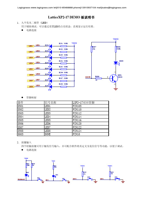
LatticeXP2-17 DEMO 板说明书1. 九个发光二极管(LED )用于辅助调试,可以通过设置LED的点亮状态,直观显示运行结果。
z 电路连接z 管脚映射2. 按键输入四个轻触按键可用于触发信号输入,并可配合软件将其定义为复位信号等功能,以便于调试。
z 电路连接telÿ010-********phoneÿ139********mailÿ********************telÿ010-********phoneÿ139********mailÿ******************** z管脚映射3.数码管显示通过两片74HC244驱动4位共阳极数码管显示。
z电路连接z管脚映射4. 拨码开关拨码开关在简单的逻辑调试时,可用作状态输入,减少额外的硬件连接。
z 电路连接z 管脚映射5. 电源方案通过设定选择开关,可为LXP2-17的4组I/O 分别选择供电电压。
评估板提供了3.3V 和Vadj 可选。
通过调节可调电阻R402,可以将Vadj 设定为1.25V 至3.3V 之间的任意电压。
z 电路连接telÿ010-********phoneÿ139********mailÿ********************z 管脚映射6. RS-232 串口z 电路连接z 管脚映射telÿ010-********phoneÿ139********mailÿ********************7. JTAG 接口z 电路连接74HC244z 管脚映射8. VGA 接口z 电路连接z管脚映射9.以太网接口z电路连接telÿ010-********phoneÿ139********mailÿ******************** z管脚映射在使用中,Pin167 RXER管脚为输入脚。
Lattice的ISPlever使用教程

[原创] Lattice的ISPlever使用教程ispLEVER使用教程目录第一节 ispLEVER 简介第二节 ispLEVER开发工具的原理图输入第三节设计的编译与仿真第四节硬件描述语言和原理图混合输入第五节 ispLEVER工具中VHDL和Verilog语言的设计方法第六节 ispVM System-在系统编程的软件平台第七节约束条件编辑器(Constraint Editor)的使用方法附录一 ispLEVER System上机实习题附录二 ispLEVER软件中文件名后缀及其含义第一节 ispLEVER 简介ispLEVER 是Lattice 公司最新推出的一套EDA软件。
设计输入可采用原理图、硬件描述语言、混合输入三种方式。
能对所设计的数字电子系统进行功能仿真和时序仿真。
编译器是此软件的核心,能进行逻辑优化,将逻辑映射到器件中去,自动完成布局与布线并生成编程所需要的熔丝图文件。
软件中的Constraints Editor工具允许经由一个图形用户接口选择I/O设置和引脚分配。
软件包含Synolicity公司的“Synplify”综合工具和Lattice的ispVM器件编程工具。
ispLEVER软件提供给开发者一个简单而有力的工具,用于设计所有Lattice可编程逻辑产品。
软件支持所有Lattice公司的ispLSI 、MACH、ispGDX、ispGAL、GAL器件。
ispLEVER 工具套件还支持Lattice新的ispXPGATM和ispXPLDTM产品系列,并集成了Lattice ORCA Foundry设计工具的特点和功能。
这使得ispLEVER的用户能够设计新的ispXPGA和ispXPLD产品系列,ORCA FPGA/FPSC系列和所有Lattice的业界领先的CPLD产品而不必学习新的设计工具。
软件主要特征:1. 输入方式* 原理图输入* ABEL-HDL输入* VHDL输入* Verilog-HDL输入* 原理图和硬件描述语言混合输入2. 逻辑模拟* 功能模拟* 时序模拟3. 编译器* 结构综合、映射、自动布局和布线4. 支持的器件* 含有支持ispLSI器件的宏库及MACH器件的宏库、TTL库* 支持所有ispLSI、MACH、ispGDX、ispGAL、GAL、ORCA FPGA/FPSC、ispXPGA和ispXPLD器件5. Constraints Editor工具* I/O参数设置和引脚分配6. ispVM工具* 对ISP器件进行编程软件支持的计算机平台:PC: Windows 98/NT/2000/XP第二节 ispLEVER开发工具的原理图输入I. 启动ispLEVER(按Start=>Programs=>LatticeSemiconductor=>ispLEVER Project Navigator)II. 创建一个新的设计项目A. 选择菜单File。
QuickTake 30 中文操作手册

QuickTake 30操作手册术语》开始键打开LED灯,在显示和无保存退出间转换。
向上和向下键上下按钮,增加或者减少取样参数,在设置条件间进行转换。
按键顺序或上或下同时按下安全编码,按顺序按下可编程的顺序》页脚内容1开机:按星号键2秒检查电池状态:按星号键选择运行预设时间:按上、下键,选择所需要的预设值,一旦发现所需要的预设值,同时按上下键开始取样。
运行或者保持:同时按上下键重复取样:一旦出现LED灯上显示Done,rSET或者SErr,同时按上下键返回到预设运行时间,然后同时按上下键取样。
改变或者校准流量:注意:流速并不在LED灯上显示。
按上、下键来选择一个运行时间,按校准键2秒(不需要安全编码)。
按上或下键改变到所需流量,然页脚内容2后按下星号键。
当STOR在LED灯上显示时,同时按上下键来存储设置或者按星号键忽略已经设置流量。
中断运行,终止取样或者重设泵值:在保持状态下,按下星号键会显示样品重设(rSEt),同时按上下键来重新设置泵或者按星号键忽略重设重新返回保持状态。
页脚内容3简述QuickTake 30 采样器是一款便携式的充电电池供电的空气采样泵,可以在接切割器或者石棉采样盒的条件下稳定提供10L/min~30L/min流量。
隔膜泵采用闭环流量控制系统,QuickTake 30可以提供稳定的恒定流量。
QuickTake 30具有可编辑运行时间的特点,提供8个预设的可编程运行时间,时间范围从1分钟到999分钟,可以在连续运行中手动停止或者进行间歇采样模式。
另外,QuickTake 30还配备了充电锂电池来保证仪器正常运行。
页脚内容4性能指标流量范围:10到30升每分钟流量精度:设置流量的±5%补偿流量的背压范围:10L/min在90英寸水柱压力下页脚内容520L/min在50英寸水柱压力下30L/min在15英寸水柱压力下典型的取样装置的背压(英寸水柱)电源:7.2V充电锂电池或者100-240V变压器电池充电时间:大约5小时页脚内容6运行时间:使用spore trap 在15L/min流量下可运行5小时使用biostage在30L/min流量下可运行4小时使用25mm,0.8微米的MCE过滤装置在10L/min流量下可运行100分钟使用37mm,0.8mm微米MCE过滤装置在10L/min流量下可运行大于14个小时。
Rattle包快速上手指南说明书

The Rattle Package:Quick Start GuideGraham Williams****************************March20,20221IntroductionRattle(Williams,2011)is a package written in R providing a graphical user interface to very many other R packages that provide functionality for data mining.This quick start guide is under development.See https:// for extensive documentation2RequirementsRattle depends on over40other R packages and a couple of other software applications/libraries that are independent of R.Thefirst thing to ensure is that you have installed the GTK+libraries and the GGobi application.This is operating system dependent and full installation instructions are available from https:///.Only a couple of R packages are dependencies for Rattle.Most are suggestions,but without them functionality is quite limited.At a minimum it is useful to ensure you have the RGtk2package installed.Others that you might like to install include:ada,arules,doBy,ellipse,fBasics,fpc, gplots,Hmisc,kernlab,mice,party,playwith,pmml,randomForest,reshape,rggobi,RGtk2, ROCR,RODBC,and rpart.The packages will usually be installed with the following command:>install.packages("rattle",dependencies=c("Depends","Suggests")) The latest beta version of rattle is available from https:///:>install.packages("rattle",repos="https://",type="source")3First StepsStart up rattle:>library(rattle)>rattle()4Sipmle Scenario:Build a Couple of Models1.Click Execute2.Click Yes(load the sample weather dataset)3.Click the Model tab4.Click Execute(to build a decision tree)5.Click Draw to display the decision tree(loads other packages as required)6.Click the Forest radio button7.Click Execute(to build a random forest-loads packages as required)8.Click the Evaluate tab9.Click the Risk radio button(installs packages as required)10.Click Execute to display two Risk(Cummulative)performance plots11.Click the Log tab12.Click the Export button to save script tofile weather script.R to home folderNow exit from R(and rattle)and start R up again.>source("~/weather_script.R")This will rerun everything that was done in the GUI session but purely as a script.5ReferencesWilliams,G.J.(2009).Rattle:A Data Mining GUI for R.The R Journal,1(2),45-55.URL: https:///archive/2009-2/RJournal2009-2Williams.pdf.Williams,G.J.(2011).Data Mining with Rattle and R:The Art of Excavating Data for Knowledge e R!series.Springer.https://bit.ly/rattle data mining.。
快斯克和快斯克+用户指南说明书

impactQuikstik andQuikStik+INSTRUCTIONSUse the two flip locks to adjust the length of the QuikStikUse the two small knobs to adjust the position of the swivel handleUse the slip lock to adjust the length of the strapSetting up your QuikStikQuikStik and QuikStik+Additional QuikStik+ AdjustmentsUsing the StrapMount the bracket you want to use on the top stud and tighten securely.Use the large side knob to adjust the tilt of the swivel handlePosition the strap so that the pocket points downward, then insert the QuikStik135246Using the QuikStik with the Impact QuikboxWithout strap, using both handsWithout strap, using both handsUsing your QuikStikQuikStik and QuikStik+Additional QuikStik+ PositionsThe QuikStik could also be used in many other configurations, such as with a standard flash bracketWith strap, using both handsWith strap, using one hand791181012This Impact product is warranted to the original purchaser to be free from defects in materials and workmanship under normal consumer use for a period of one (1) year from the original purchase date or thirty (30) days after replacement, whichever occurs later. The warranty provider’s responsibility with respect to this limited warranty shall be limited solely to repair or replacement, at the provider’s discretion, of any product that fails during normal use of this product in its intended manner and in its intended environment. Inoperability of the product or part(s) shall be determined by the warranty provider. If the product has been discontinued, the warranty provider reserves the right to replace it with a model of equivalent quality and function.This warranty does not cover damage or defect caused by misuse, neglect, accident, alteration, abuse, improper installation or maintenance. EXCEPT AS PRO VIDED HEREIN, THE WARRANTY PRO VIDER MAKES NEITHER ANY EXPRESS WARRANTIES NO R ANY IMPLIED WARRANTIES, INCLUDING BUT NO T LIMITED TO ANY IMPLIED WARRANTY O F MERCHANTABILITY OR FITNESS FOR A PARTICULAR PURPOSE. This warranty provides you with specific legal rights, and you may also have additional rights that vary from state to state.To obtain warranty coverage, contact the Impact Customer Service Department to obtain a return merchandise authorization (“RMA”) number, and return the defective product to Impact along with the RMA number and proof of purchase. Shipment of the defective product is at the purchaser’s own risk and expense.For more information or to arrange service, visit or call Customer Service at 212-594-2353. Impact is a registered trademark of the Gradus Group.© 2015 Gradus Group LLC. All Rights Reserved.WarrantyGG2。
Dell Streak 快速入门指南说明书

Dell™ Streak Quick Start Guide 快速入门指南快速啟動指南________________Information in this document is subject to change without notice.©2010Dell Inc.All rights reserved.Dell and the DELL logo are trademarks of Dell Inc.June 2010P/N WD01R Rev. A00________________本说明文件中的信息如有更改,恕不另行通知。
©2010Dell Inc.版权所有,翻印必究。
Dell和DELL 徽标是 Dell Inc. 的商标。
2010 年 6 月P/N WD01R Rev. A00________________本文件中的內容若有更改恕不另行通知。
©2010Dell Inc.版權所有,翻印必究。
Dell及DELL 徽標均為 Dell Inc. 的商標。
2010 年 6 月P/N WD01R Rev. A00Remove the back cover 卸下背面盖|卸下後面板Insert the SIM card插入SIM卡|插入SIM卡Insert the battery插入电池|插入電池Insert the microSD card插入 microSD 卡|插入microSD卡Replace the back cover装回背面盖|裝回後面板Charge the battery为电池充电|電池充電1. Back button后退按钮 |返回按鍵8. Ambient light sensor环境光传感器 |周遭環境燈光感應器11. Volume up button增大音量按钮 |音量增強按鈕2. Menu button菜单按钮 |目錄按鍵9. Headphone connector耳机连接器 |耳機連接器12. Power and Sleep/Wake button电源和休眠/唤醒按钮 |電源與睡眠/喚醒按鍵3. Home button主页按钮 |首頁按鍵10. Volume down button减小音量按钮 |音量減弱按鍵13. Camera button照相机按钮 |相機按鍵4. Microphone麦克风 |麥克風5. Proximity sensors近接传感器 |近接感應器6. Earpiece耳机|耳機7. Front-facing camera lens 正面照相机镜头 |前置相機鏡頭131210123 9114 65781. Camera lens照相机镜头 |相機鏡頭2. Camera flash照相机闪光灯 |相機閃光燈3. 30-pin connector30 针连接器 | 30 插腳連接器4. Speaker扬声器 |揚聲器3124Press and hold the power button按住电源按钮|按住電源按鍵NOTE: The device will turn off automatically if you removethe back cover while the device is on.注: 当在设备开启期间卸下背面盖时,设备将自动关机。
Silk Test 16.0 Silk4J 快速入门教程说明书

Silk4J 快速入门教程Borland Software Corporation700 King Farm Blvd, Suite 400Rockville, MD 20850Copyright © Micro Focus 2015. All rights reserved. Portions Copyright © 1992-2009 BorlandSoftware Corporation (a Micro Focus company).MICRO FOCUS, the Micro Focus logo, and Micro Focus product names are trademarks orregistered trademarks of Micro Focus IP Development Limited or its subsidiaries or affiliatedcompanies in the United States, United Kingdom, and other countries.BORLAND, the Borland logo, and Borland product names are trademarks or registeredtrademarks of Borland Software Corporation or its subsidiaries or affiliated companies in theUnited States, United Kingdom, and other countries.All other marks are the property of their respective owners.2015-02-12ii内容Silk4J 快速入门教程 (4)启动 Silk4J (4)创建 Silk4J 项目 (4)录制针对保险公司 Web 应用程序的测试 (5)回放针对保险公司 Web 应用程序的测试 (6)内容 | 3Silk4J 快速入门教程本教程按步骤介绍如何使用 Silk4J 测试使用动态对象识别的 Web 应用程序。
React入门实用技巧汇总
React入门实用技巧汇总React是一种流行的JavaScript库,用于构建用户界面。
它提供了开发单页面应用程序所需的工具和组件。
在本文中,我们将介绍一些React的入门实用技巧,帮助您更好地理解和应用React。
一、使用函数组件函数组件是React中的一种常见方式,它是一种无状态的组件,只接收props作为输入并渲染输出。
它通常比类组件更简洁、易读和易于测试。
下面是一个使用函数组件的示例:```import React from 'react';function Welcome(props) {return <h1>Hello, {}!</h1>}export default Welcome;```二、使用hooksHooks是React 16.8引入的新特性,它允许我们在不编写类组件的情况下使用状态和其他React特性。
通过使用useState和useEffect等钩子函数,我们可以更方便地管理组件的状态和副作用。
以下是一个使用useState和useEffect的示例:```import React, { useState, useEffect } from 'react'; function Example() {const [count, setCount] = useState(0);useEffect(() => {document.title = `You clicked ${count} times`; });return (<div><p>You clicked {count} times</p><button onClick={() => setCount(count + 1)}> Click me</button></div>);}export default Example;```三、使用条件渲染在React中,我们可以根据条件来决定是否渲染特定的组件或内容。
Illustrator_基本操作

Illustrator_基础知识什么是IllustratorAdobe Illustrator是一款矢量绘图软件,可以又快又精确的做出彩色或黑白图形,也可以设计出任意形状的特殊文字并置入影像。
Illustrator的用途Logo设计与制作、包装设计、海报、画册、商业插图、网页设计等。
基本概念:路径:由一个或多个直线段或曲线段组成,由锚点进行连接,通过调整锚点,可以调整相应路径段。
锚点:即标记路径段的端点。
文件新建:新建文件Ctrl+N出血概念出血的作用主要是保护成品,裁切时为了防止留白边或将有用的信息剪切掉,而在设定文档大小时故意将边缘部分加宽一定距离,印刷品一般预留出血为3mm。
常规设置编辑——常规Ctrl+K设置缓存盘、参考线和网格、用户界面、智能参考线等文件打开、保存、关闭打开:Ctrl+O保存:Ctrl+S关闭:Ctrl+W画板工具Shift+O利用画板工具改变画布方向、大小“色板”面板“色板”面板提供了很多不同的颜色,用户可以从现有的色板中选择颜色,也可以创建自己的颜色导入库。
“颜色”面板颜色面板提供色谱、各个颜色值滑块和颜色值文本框。
吸管工具:可以对图稿中的颜色进行取样快捷键:I填色\描边、拾色器移动、放大/缩小查看对象抓手工具H按住空格键移动查看放大镜工具Z 按住Alt键缩小组合键Ctrl+加号放大Ctrl+减号缩小画板适合窗口大小Ctrl+0实际大小Ctrl+1选择、移动、复制、删除对象1)选择工具:用于选择、移动、缩放、旋转路径快捷键:V2)按住Shift等比例缩放按住Shift+Alt沿中心等比例缩放3)直接选择工具:用于选择锚点,调节锚点手柄快捷键:A4)复制粘贴Ctrl+C 复制Ctrl+V 粘贴Ctrl+F 粘贴至前一层Ctrl+B 粘贴至后一层选中对象按住Alt键拖移对象进行复制选中对象按住Shift 水平移动对象5)Ctrl+D 重复上一个步骤6)Ctrl+Z 还原上一个步骤7)删除Delete魔棒工具:主要用于选取具有相同或相近属性的对象,如:有相近的填充颜色、边线色、边线宽度、透明度或混合模式快捷键:Y套索工具:通过套索工具可以以自由拖曳的方式来选取多个图形对象,区域内锚点或路径片段。
快速上手指南说明书

QUICK-STARTGUIDEQuick-start guide Kurzanleitung Guide de démarrage rapide Guida rapida Guía de inicio rápido Guia de Início Rápido Egyszerű útmutató Īsā pamācība Ghid de pornire rapidă快速入门指南QUICK-START GUIDEReady to play!Bereit zum Spielen! PRÊT À ÊTRE UTILISÉ !Pronto per il gioco! ¡Listo para jugar! Preparar para Jogar! Játékra kész! Sagatavojies spēlei! Gata de joacă!准备玩乐!READY TO PLAY!1124352xAAA71387and/or71403 is neededGET THE LATEST VERSION OF THE APP!HOL DIR DIE NEUESTE VERSION DER APP!OBTIENS LA DERNIÈRE VERSION DE L’APPLICATION !SCARICA L’ULTIMA VERSIONE DELL’APP ¡DESCARGA LA VERSIÓN MÁS RECIENTE DE LA APP!OBTÉM A ÚLTIMA VERSÃO DA APP!TÖLTSD LE AZ ALKALMAZÁS LEGÚJABB VERZIÓJÁT!IEGŪSTI JAUNĀKO LIETOTNES VERSIJU!OBȚINE CEA MAI RECENTĂ VERSIUNE A APLICAȚIEI!获取此应用程序的最新版本!LEGO® Super Mario TM /devicecheckCheck for compatibility Kompatibilität prüfen Vérifier la compatibilité Controlla la compatibilità Comprueba tu compatibilidad Verificar a compatibilidade Ellenőrizd a kompatibilitást Pārbaudīt saderību Verificarea compatibilității 检查兼容性GET THE LATEST VERSION OF THE APP!34Update your interactive figure Aktualisiere deine interaktive Figur Mets ta figurine interactive à jour Aggiorna il tuo personaggio interattivo Actualiza tu figura interactiva Atualiza a tua figura interativaFrissítsd az interaktív figurád! Atjaunini savu interaktīvo figūru Actualizează figurina ta interactivă更新交互式玩偶UPDATEYOUR INTERACTIVE FIGURE714087140371404Starter Course 71360 and/or 71387 and/or 71403 needed Starterset 71360 und/oder 71387 und/oder 71403 wird benötigt Pack(s) de démarrage 71360 et/ou 71387 et/ou 71403 nécessaire(s)Starter Pack 71360 e/o 71387 e/o 71403 necessari Se necesita el Pack Inicial 71360 y/o 71387 y/o 71403Necessita do Pack Inicial 71360 e/ou 71387 e/ou 71403A 71360-as és/vagy a 71387-es és/vagy a 71403-as Kezdőpálya szükséges Nepieciešams sākuma maršruta komplekts 71360 un/vai 71387, un/vai 71403Este nevoie de Setul de bază 71360 și/sau 71387 și/sau 71403 需要入门套组 71360 和/ 或 71387 和/或 71403OROROR ODER OU O VAGY VAI SAU 或7140471407714057140671409714087136071387714037140671405714097136071360 71407OR OR 713607140371387Starter Course 71360 or 71387 or 71403 needed Starterset 71360 oder 71387 oder 71403 wird benötigt Pack de démarrage 71360 ou 71387 ou 71403 nécessaire Starter Pack 71360 o 71387 o 71403 necessario Se necesitan los sets Pack Inicial 71360 o 71387 o 71403Necessita do Pack Inicial 71360 ou 71387 ou 71403A 71360-as vagy a 71387-es vagy a 71403-as Kezdőpálya szükséges Nepieciešams sākuma maršruta komplekts 71360 vai 71387 vai 71403Este necesar Setul de bază 71360, 71387 sau 71403需要入门套组 71360 或 71387 或 71403Team up for new adventures Erlebt gemeinsam neue Abenteuer Forme une équipe pour vivre de nouvelles aventures Gioca con gli amici per nuove avventure Forma equipo y vive nuevas aventuras Junta-te à equipa para novas aventuras Játssz csapatban az új kalandokértApvienojiet spēkus jauniem piedzīvojumiem Intră într-o echipă pentru noi aventuri 一起踏上全新的探险之旅71360 + 71403OR ODER OU O VAGY VAI SAU 或71360 + 7140371387 + 71403TEAM UP FOR NEW ADVENTURESStarter Course 71403 and 71360 neededStartersets 71403 und 71360 werden benötigtNecessita do Pack Inicial 71403 e 71360 A 71403-as és a 71360-as Kezdőpálya szükséges Packs de démarrage 71403 et 71360 nécessaires Starter Pack 71403 e 71360 necessari Se necesita el Pack Inicial 71403 y 71360Nepieciešami sākuma maršruta komplekti 71403 un 71360Este nevoie de Setul de bază 71403 și 71360需要入门套组 71403 和 71360++714037136071410714107136071360714107141071410714107141071410714107140371403LEAF NO. 3 caledThis radio equipment declaration has to be adaptedto the product – insert product name(s) below:FCC_RadioCaution risk of explosion FCC_RadioFCC_RadioFCC_RadioFCC_RadioTaiwan_Radio NCC logo:Mexico_RadioBrazil_Radio Australia Radio symbol Bluetooth low energy symbol Singapore Radio symbolTaiwan_Radio Mexico_RadioBrazil_Radio Australia Radio symbol Bluetooth low energy symbol Singapore Radio symbol Taiwan_Radio Mexico_Radio Brazil_Radio Australia Radio symbol Bluetooth low energy symbol Singapore Radio symbol Taiwan_Radio Brazil_RadioAustralia Radio symbol Bluetooth low energy symbol Singapore Radio symbol Taiwan_Radio Australia Radio symbol Bluetooth low energy symbol Singapore Radio symbol Taiwan_RadioNCC logo:Thailand_Radio (ONLY added LE products) NCC logo:Caution risk of explosionUpdated:28.04.21L_China RoHs info/service 6429363 LEGO, the LEGO logo and the Brick and Knob configurations are trademarks and/or copyrights of the LEGO Group.©2022 The LEGO Group.TM & © 2022 Nintendo.。
LatticeXO中文使用教程

LatticeXO中⽂使⽤教程Lattice MachXO TM设计指南v1.11.介绍 (4)1.1特征 (4)1.2产品系列和器件选择⼿册 (5)1.3性能分析 (6)2.体系结构 (7)2.1M ACH XO结构概述 (7)2.1.1PFU结构 (7)2.1.2Slice结构 (8)2.1.3布线资源 (9)2.2结构特征 (9)2.2.1时钟/控制信号⽹络 (9)2.2.2锁相环PLL (10)2.2.3⽚内时钟振荡器 (11)2.2.4嵌⼊块RAM (EBR) (11)2.2.5I/O特性 (11)2.2.6休眠模式 (13)2.2.7器件编程 (13)3.设计综合&实现 (14)3.1开发流程 (14)3.2设置约束项 (16)3.2.1设置I/O位置 &属性 (16)3.2.2设置时钟频率|周期 (16)3.2.3设置建⽴&保持时间 (17)3.2.4设置Tco时间 (19)3.2.5设置MutiCycles | MaxDelay | Tpd (20)3.2.6时序约束例外(BLOCK) (20)3.2.7信号分组 (20)4.器件应⽤要点 (21)4.1M ACH XO系列器件V CC,V CCAUX,V CCIO作⽤和连接 (21) 4.2M ACH XO系列器件各电源上电顺序及要求 (21)4.3M ACH XO热插拔应⽤注意事项 (21)4.4如何使⽤全局复位功能 (22)4.5如何使⽤全局输出三态功能 (22)4.6如何使⽤全局时钟 (23)4.7如何使⽤TFR功能(透明现场升级) (23)4.8如何使⽤M ACH XO的差分信号 (24)4.9如何接⼝5V输⼊信号 (25)4.10如何在同⼀B ANK使⽤不同I/O⼝电平标准 (25)4.11如何减⼩T CO时间 (26)4.12什么-M速度级别? (27)4.13如何获得时序分析结果? (27)4.14如何知道资源利⽤率 (28)4.15如何使⽤M ACH XO的块RAM(EBR) (28)4.16如何利⽤PFU⽣成移位寄存器和分布式RAM (29)4.17如何使⽤锁相环(PLL) (30)4.18下载接⼝(TAP)的连接建议 (30)4.19如何设置加密位和⽤户代码 (30)4.20如何使⽤P OWER C ACULTOR估计功耗 (31)4.21如何快速建⽴器件原理图库? (32)4.22如何选择综合⼯具? (32)4.23关于约束⽂件 (32)4.24如何使⽤M ODELSIM 进⾏仿真 (33)5.相关资料 (33)1.介绍MachXO器件是 Lattice 公司基于FLASH+SRAM技术CPLD器件。
AutoHotkey初级教程

指南和概述这个简短的介绍将帮助你马上开始编写你自己的宏和热键脚本。
指南目录•创建一个脚本•启动一个程序或文档•发送键击和鼠标点击•激活与操纵窗口•从用户使用的MsgBox, InputBox 等命令来获取输入的数据•使用变量和剪贴板•一遍遍地重复一系列动作•操纵文件和文件夹•其他功能的概述创建一个脚本每个脚本都是一个包含命令的要被程序(AutoHotkey.exe)执行的纯文本文件。
一个脚本也可能包含热键和热字串,甚至于全部由它们组成。
不过,在没有热键和热字串时,一个脚本从它被启动时起,将从头至尾顺序地执行它的命令。
要创建一个新脚本:1打开Windows 资源管理器并进入一个你选择的文件夹。
2拉下文件菜单并选择新建>> AutoHotkey Script (或新建>> 文本文档)。
3给文件键入一个名称,确保它以.ahk结尾。
例如:Test.ahk4鼠标右键点击此文件并选择Edit Script。
5在一个新的空行,键入下述内容:#space::Run 符号# 表示Windows 键,因此#space 意味着按住Windows 键然后按下空格键来激活一个热键。
符号:: 意味着每次按下此热键时,随后的命令将会被执行,在此例中将转到Google 网站。
要试用此脚本,按下述内容继续操作:6保存并关闭此文件。
7在Windows 资源管理器中,鼠标双击来启动脚本。
一个新的系统托盘图标出现。
8按住Windows 键并按下空格键。
一个网页在默认浏览器中打开。
9要退出或编辑此脚本,鼠标右键点击它的系统托盘图标。
注意:多个脚本能被同时运行,每个带有它自己的托盘图标。
此外,每个脚本能拥有多个热键和热字串。
启动一个程序或文档Run命令用来启动一个程序、文档、URL(统一资源定位符) 或者快捷方式。
这里有一些普通的例子:Run NotepadRun C:\My Documents\Address List.docRun C:\My Documents\My Shortcut.lnkRun Runmailto:**********************一个热键通过包含一个热键标记能被分配给以上任何一个例子。
- 1、下载文档前请自行甄别文档内容的完整性,平台不提供额外的编辑、内容补充、找答案等附加服务。
- 2、"仅部分预览"的文档,不可在线预览部分如存在完整性等问题,可反馈申请退款(可完整预览的文档不适用该条件!)。
- 3、如文档侵犯您的权益,请联系客服反馈,我们会尽快为您处理(人工客服工作时间:9:00-18:30)。
(m aven):
用户服务)、缓存容量、静态资源版本等
●框架本地实现配置(src/main/resources/local.properties),当运行环境是本地容器
(latke.props 中runtimeEnv=LOCAL 或者是BAE)时才需要此配置,定义了本地容
器相关参数,例如数据库、JDBC 配置等
●数据库表结构(src/main/resources/repository.json),定义了数据库表结构,用于生
成建表语句以及持久化时的校验
●部署描述符(src/main/webapp/WEB-INF/web.xml),定义了框架启动Servlet 监听器、
请求分发器等
请求处理
客户端的HTTP 请求会经过Latke 分发到应用定义的请求处理器上(标注有
@RequestProcessor 的类),一个请求处理器可以包含多个请求处理方法(标注有
@RequestProcessing 的方法),每个方法可以对应多个请求地址。
可以看作是SpringMVC 中控制器的简要实现,略有不同的是在响应的处理上。
响应渲染器会生成不同类型的响应,例如HTML、Rss、PNG 等:
服务调用
通过@Inject 注入需要的服务到字段上:
服务实现
●@Service 标注了该类是一个服务
●@Transactional 标注了该方法是执行在一个事务中。
事务隔离为
READ_COMMITTED,传播类型为REQUIRED
数据存取库
●@Repository 标注了该类是一个数据存取库
●数据存取库需要继承AbstractRepository
●在构造数据存取库时需要指定该数据存取库的名字,该名字对应repository.json 中的
描述
注意:初始化表JdbcRepositories.initAllTables() 最好通过单独的初始化程序来做,调用这个方法后会根据repository.json 的描述生成建表SQL 并执行。
GAE 上面的Datastore 无需初始
化即可使用,所以如果在GAE 上使用Latke,则可以不调用初始化表方法。
小结
●框架使用非常类似Spring
●应用基于JSON,更适合快速开发
限制
IoC
Bean 的生存周期(Scope)默认是单例(Singleton),其他生存周期(例如
Application、Request、Session、Dependent 等)目前Latke 尚未实现。
Latke 提倡的是服务端无状态设计,应用性能可以最优化并降低设计难度。
当然,有状态的设计也是可以的,所以这些生存周期后续会逐渐提供支持。
最佳实践
表名前缀
在local.properties 中有一项配置jdbc.tablePrefix,如果配置了该项,则初始化表(JdbcRepositories.initAllTables())时生成的表名就会带有前缀。
建议应用配置该项,以屏蔽不同数据库迁移数据时关键字对表名的影响。
实体模型
Lakte 使用JSON 作为实体载体,管理JSON 的键就是对实体的建模。
实体的键对应了数据库表列名,实体内嵌的关联对象是服务中组装的。
例如对于用户实体,键包含了简单类型属
“”
、age””
,关联类型属性:books”,构造的对象例如:
“
性:name”“
{
“name”: “Daniel”,
“age”: 23,
“books”: [{
“name”: “TAO of Life”
}, ….]
}
键管理可以通过User 类:
public class User {
public static final String USER_NAME = “name”;
public static final String USER_AGE = “age”;
public static final String USER_T_BOOKS = “books”;
}
T表示这个属性是非持久化的(User 表中无此列),是通过在服务中组装而来。
repository.json
这个文件可以手工编写,然后使用JdbcRepositories#initAllTables 方法自动创建数据库;也可以使用JdbcRepositories#initRepositoryJSON 方法从已有数据库表生成这个文件。
repository.json -> tables:
●不用对不同数据库编写SQLs
●可以运行时建表
●从业务逻辑实现开始的开发方式
tables -> repository.json:
●在已有tables 上继续开发
●从DB 开始的开发方式
这两种方式没有什么本质上的区别,可由开发自由决定。
关联查询
实体JSON 对象中的关联属性是通过组装而来,需要先把这个属性查询出来,再编程组装到这个实体JSON 对象中。
这一点相对于一些ORM 框架(例如Hibernate)来说是比较繁琐,但这样做的优势之一就是能够使实体变得更灵活。
TBD:后续Latke Repository 会提供类似MyBatis 的机制,通过配置查询SQL,执行后返回投影键的JSON。