电动阀门执行器出口英文使用说明书
电动阀门电动驱动器说明书
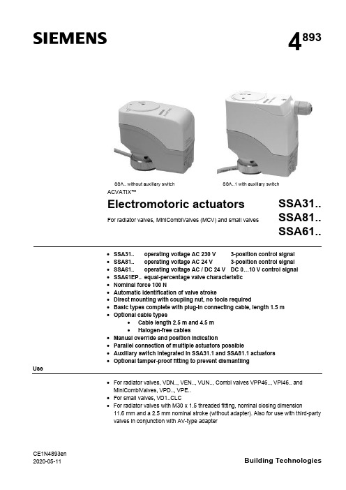
CE1N4893en 2020-05-11Building Technologies4893SSA.. without auxiliary switch SSA..1 with auxiliary switchACVATIX™Electromotoric actuatorsFor radiator valves, MiniCombiValves (MCV) and small valvesSSA31..SSA81..SSA61..·SSA31.. operating voltage AC 230 V 3-position control signal ·SSA81.. operating voltage AC 24 V 3-position control signal ·SSA61.. operating voltage AC / DC 24 V DC 0…10 V control signal ·SSA61EP.. equal-percentage valve characteristic ·Nominal force 100 N·Automatic identification of valve stroke·Direct mounting with coupling nut, no tools required·Basic types complete with plug-in connecting cable, length 1.5 m ·Optional cable types·Cable length 2.5 m and 4.5 m ·Halogen-free cables·Manual override and position indication·Parallel connection of multiple actuators possible·Auxiliary switch integrated in SSA31.1 and SSA81.1 actuators ·Optional tamper-proof fitting to prevent dismantlingUse·For radiator valves, VDN.., VEN.., VUN.., Combi valves VPP46.., VPI46.. and MiniCombiValves, VPD.., VPE..·For small valves, VD1..CLC· For radiator valves with M30 x 1.5 threaded fitting, nominal closing dimension11.6 mm and a 2.5 mm nominal stroke (without adapter). Also for use with third-party valves in conjunction with AV-type adapter2/10SiemensCE1N4893enSmart InfrastructureBuilding Technologies2020-05-11· For modulating or 3-position control in heating systems, chilled ceilings and terminal units.Type summaryTypereference Operating voltage Run time at 50 HzControl signalConnecting cableAuxiliary switchSSA31AC 230 V150 s3-position1.5 m SSA31/001)no cable SSA31.1 1.5 m YesSSA81AC 24 V1.5 m SSA81/001)no cable SSA81.1 1.5 m YesSSA61AC / DC 24 V 34 s DC 0...10 V1.5 m SSA61/001)no cable SSA61EP 2) 1.5 m SSA61EP/002)no cable1)For available cable lengths or terminal block connectors refer to "Accessories", page 42)With equal-percentage valve characteristicTypereference DescriptionOperating voltage Control signalASY3L25Connecting cable 2.5 mAC 230 V3-positionASY3L45Connecting cable 4.5 m ASY8L25Connecting cable 2.5 m AC 24 V ASY8L45Connecting cable 4.5 mASY8L45HF Connecting cable 4.5 m, halogen-free, VDE 0207-24ASY6L25Connecting cable 2.5 m AC / DC 24 V DC 0...10 V ASY6L45Connecting cable 4.5 m ASY6L45HF Connecting cable 4.5 m, halogen-free, VDE 0207-24ASY98Retaining screw for terminal block connectors. Included in ASY99 and ASY100.ASY99Terminal block connector for 3-position actuators SSA81../00ASY100Terminal block connector for DC 0…10 V modulating actuators SSA61/00AL40Tamper-proof fitting to prevent dismantling of actuators Adapter typefor third-party valves Adapter type for third-party valves AV51Beulco old (M30x1.0)AV56Giacomini AV522)Comap AV57Herz AV53Danfoss RA-N (RA2000)AV58Oventrop old (M30x1.0), till 2002AV54Danfoss RAVL AV592)Vaillant AV55Danfoss RAV AV60TA, till 20021)AV61Markaryd (MMA)1) No adapter required for type TBV-C 2)While stocks lastOrdering Type Stock no.DescriptionQuantity SSA81/00SSA81/00Electromotoric actuator 2ASY8L45ASY8L45Connecting cable2Actuators, valves and accessories are packed separately. Items are suppliedindividually packed.Overview tables, see page 9.AccessoriesExample:DeliveryRev.-No.3/10SiemensCE1N4893en Smart Infrastructure2020-05-11Equipment combinationsk vs = nominal flow rate of cold water (5...30 °C) through the fully open valve (H 100)at a differential pressure of 100 kPa (1 bar)V & = Nominal volume flow at 0.5 mm strokeTo ensure trouble-free operation of third-party valves with the SSA.. actuator, the valves must satisfy the following requirements:·Threaded connections with coupling nut M30 x 1.5·Nominal force F £ 100 N ·Dimension x x > 9.0 mm ·Dimension y y £ 14.5 mmFunction / mechanical designWhen the actuator is driven by DC 0…10 V control voltage or by a 3-position signal, it produces a stroke which is transmitted to the valve stem.The description of operation in this document applies to the valve versions which are fully open when de-energized (NO).·Voltage at Y1:Stem retracts Valve opens ·Voltage at Y2:Stem extends Valve closes ·No voltage at Y1 and Y2:Actuator maintains its current position· The valve opens / closes in proportion to the control signal at Y.· At DC 0 V, the valve is fully closed (A à AB).· When power supply is removed, the actuator maintains its current position.1)Actuator is calibrated to 2.5 mm stroke of VPI46.15.L06S t r o k e 2,5 m m ((c a l i b r a t e d )1)22.51.510.500246810control signal Y [V]Type reference Valve type k vs [m 3/h]V&[l/h]PN class Data sheet VDN.., VEN.., VUN..Radiator valves 0.09…1.41PN 10N2105, N2106VPD.., VPE..MCV radiator valves 25…483N2185VD1..CLC Small valves 0.25…2.60N2103VPP46.., bi valves 30…4001PN 25N4855For other radiator valves with type AV.. adapters refer to "Type summary / accessories"Radiator valves (M30 x 1.5) from other manufacturers, without adapter:· Heimeier · Crane D981..· TA-Type TBV-C · Oventrop M30 x 1.5 (from 2001)· MNG · Junkers · Honeywell-Braukmann · Cazzaniga · Beulco (new)Valves from othermanufacturers3-position control signalSSA31.. / SSA81..DC 0...10 V control signalSSA61, SSA61/004/10SiemensCE1N4893enSmart InfrastructureBuilding Technologies2020-05-11Combi valves VPI46../VPP46.. in combination with SSA61EP.. have an equal-percentage characteristics.· The valve opens / closes in equal percentage ratio to the control signal at Y.· At DC 0 V, the valve is fully closed (A à AB).· When power supply is removed, the actuator maintains its current position.1)Actuator is calibrated to 2.5 mm stroke of VPI46.15L06S t r o k e 2,5 m m (c a l i b r a t e d )1)2.42.51.510.500246810control signal Y [V]·Plastic housing·Locking-proof, maintenance-free gear train·Manual override with hexagonal socket wrench 3 mm ·Reduced power consumption in the holding positions·Load-dependent switch-off in the event of overload and in stroke end positions·Parallel operation of 6 SSA31.., 24 SSA81.. and 10 SSA61..possible, provided the controllers’ output is sufficient ·Terminal block connectors for customer made cables available (only for use with AC 24 V and AC / DC 24 V actuators)·Connecting cables with AC 24 V and AC 230 V connectors cannot be mixed up·Halogen-free cables availableAccessoriesAdapter types AV51 to AV61 are available for mounting the SSA.. actuators on third-party radiator valves as shown under "Type summary/accessories", page 2.1xtighten gentlyType ASY98 to secure the cable connector. Included in ASY99 and ASY100.The cable connector snaps into position,but can be additionally secured with the retaining screw.DC 0...10 V control signal SSA61EP,SSA61EP/00Features and advantagesAdapter type AV.. for third-party valves Tamper-proof fitting AL40Retaining screw ASY985/10SiemensCE1N4893en Smart Infrastructure2020-05-11For special cable lengths of the AC / DC 24 V actuators.·Type ASY99 for 3-position actuators SSA81../00·Type ASY100 for DC 0…10 V modulating actuators SSA61/00The terminal block connectors are supplied complete with mounting instructions (74 319 0385 0).Notes The actuators must be electrically connected in accordance with local regulations (refer to "Connection diagrams", page 9).Regulations and requirements to ensure the safety of people and property must be observed at all times!The permissible temperatures (refer to "Technical data", page 7) must be observed.The connecting cable of the actuator may come into contact with the hot valve body,provided the temperature of the valve body does not exceed 80 °C.Actuator types SSA 31.1 and SSA81.1 have a built-in auxiliary switch. The switch cannot be fitted in other actuators later.Mounting instructions (Ref. 74 319 0497 0) are enclosed in the product packaging.The actuator and valve are assembled with the coupling nut; no tools or adjustments are required.The actuator must be fitted in position 1 with the power disconnected (refer also to "Manual override", page 6):·Position the actuator and tighten the coupling nut manually ·Do not use any tools such as wrenches·Avoid lateral pressure or (cable) tension on the mounted actuator!In the case of actuators without a connecting cable (SSA../00), the separately orderedCrimp ferrule on stripped wire of connecting cable.When commissioning, check the wiring and the functioning of the actuator and auxiliary switch, if fitted.·Actuator stem extends (from position 1 to 0): Valve closes ·Actuator stem retracts (from position 0 to 1): Valve opens During commissioning and whenever the operating voltage is switched on,the SSA61.. runs a self-calibration routine. (Valve stroke 0® Max.stroke ® Setpoint).Never intervene manually in this process.ON0 %EngineeringMountingOrientationInstallationCommissioningTerminal block connectors ASY99ASY1006/10SiemensCE1N4893enSmart InfrastructureBuilding Technologies2020-05-11The second or third attempt at calibration occurs automatically after an 8-minute delay.After three failed calibration attempts the actuator stem remains in the extended position and the radiator valves are closed.For valves with strokes < 1.5 mm, the actuator/valve combination locks after three failed calibration attempts.The new Siemens type VDN.., VEN.. and VUN.. radiator valves have in all 1.5 mm stroke.A 3 mm hexagonal socket wrench can be used to move the actuator to any position.However, if a control signal from the controller is present, then this takes priority in determining the position.To retain the manually set position, unplug the connecting cable or switch off the operating voltage and the control signal.2.5 mm stroke5.5 mm strokeThe actuators are maintenance-free.When carrying out service work on the plant, following must be noted:·Turn power off (e.g. remove the plug)·If necessary, disconnect electrical connections from the terminals·The actuator must be commissioned only with a correctly mounted valve in place!SSA.. actuators cannot be repaired; the complete unit must be replaced.DisposalWarrantyThe technical data given for these applications is valid only when the actuators are used with the Siemens valves listed under "Equipment combinations", page 2.The use of the SSA.. actuators in conjunction with third-party valves invalidates any warranty offered by Siemens Building Technologies / HVAC Products.Note: Correctcalibration is only possible ·with valve·stroke > 1.5 mmOperationNoteManual overrideMaintenance!Repair7/10SiemensCE1N4893en Smart Infrastructure2020-05-11Technical dataPower supplyControlFunctional dataElectrical connectionsNorms and directivesDimensions /weight Housing colors 1)Provided the controller output is sufficient2)The documents can be downloaded from /bt/download8/10SiemensCE1N4893enSmart InfrastructureBuilding Technologies2020-05-11General ambient conditionsOperation EN 60721-3-3Transport EN 60721-3-2Storage EN 60721-3-1Environmental conditions Class 3K3Class 2K3Class 1K3Temperature +1...+50 °C –25...+70 °C –5...+50 °C Humidity 5...85 % r.h.< 95 % r.h. 5...95 % r.h.Connecting cableConnection terminalsY2Y1G4864Z 15Control signal CLOSE Control signal OPENSystem potential AC 24 VG0Y G4864Z 16System neutralControl signal DC 0...10 V System potential AC/DC 24 VFactory setting: 50 %0...50 % Q11® Q1250...100 % Q11® Q14The switching point can be adjusted by turning the switching cam with a screwdriver (see Mounting Instructions).Recommended connecting cable: H03VV-F, 2x0.5…0.75 mm 2.ASY3L.. with SSA31..ASY8L.. with SSA81..ASY6L.. with SSA61..ASY99for SSA81..ASY100for SSA61..Terminals for auxiliary switchesSSA31.1, SSA81.19/10SiemensCE1N4893en Smart Infrastructure2020-05-11Connection diagramsN Controller Y ActuatorL System potential AC 230 V NSystem neutralY1, Y2Control signal OPEN, CLOSE Q1, Q2Controller contactsN Controller YActuatorSP, G System potential AC 24 V SN, G0System neutralY1, Y2Control signal OPEN, CLOSE Q1, Q2 Controller contactsN Controller YActuatorSP, G System potential AC 24 V SN, G0System neutral Y Control signalSSA31..SSA81..SSA61..10/10SiemensCE1N4893enSmart InfrastructureBuilding Technologies2020-05-11DimensionsDimensions in mm8377484893M 0172.59M30 x 1,54893M 0298.5834889.5M30 x 1,59Revision numbersType reference Valid from Rev.-No.Type reference Valid from Rev.-No.SSA31K SSA61K SSA31/00K SSA61/00KSSA31.1K SSA81K SSA81/00K SSA81.1KActuator without auxiliary switch SSA31..SSA81..SSA61..Actuator with auxiliary switch SSA31.1..SSA81.1..Issued bySiemens Switzerland LtdBuilding Technologies Division International Headquarters Theilerstrasse 1a 6301 Zug SwitzerlandTel. +41 41-724 24 24/buildingtechnologies © Siemens Switzerland Ltd, 2005Technical specifications and availability subject to change without notice.。
KFD阀门控制箱中英文说明书

额定电流(安培)调节型适用电装型号Ⅲ配型、型Ⅳ配型结构形式:、抽屉式、小型R ated current (am pere)T A djusting typeZ W Q W JQ A pplicable type of electric fitting: for ZW type and Q W type.C X G Structure from : C draw er type, X sm all C ontrol cabinet of electric valve cabinetⅢⅣ抽屉式、挂壁式、、、阀门电动装置控制箱for JQ type draw er type, G wall type K F D —— 普 通 型 KFD 系 列 Common type KFD series一、概 述 Brief introduction该系列电动阀门控制箱,是与我厂生产的ZW 型、JQ 型及QW 型阀门电动装置配套使用的电控箱,用于控制阀门的开启和关闭,可用于现场单独控制或远方集中控制。
KFD 型电控箱有抽屉式和挂壁式两种结构。
This series of control cabinet of electric valve is the one to be used together with ZW type, JQ type and QW type electric valve actuator produced by our company and to control the opening and closing of valve. It can be used in site individual control or long-distance centralized control.KFD type electric control cabinet has two kinds of structure: drawer type and wall type. Designation型号表示方法 Designation二、技术数据 T echnical data1、电源:380V 50Hz 三相四线制(特殊要求,另见)2、工作环境:(1)环境温度:—20℃~+60℃ (2)相对湿度:≤85%(20℃时)(3)周围不含强腐蚀性、易燃易爆介质及导电尘埃。
电动蝶阀使用说明书中英文

电动蝶阀使用说明书中英文电动蝶阀Electric Butterfly Valve使用说明书Operation Manual一、用途Ⅰ.Application本系列蝶阀适用于冶金、矿山、建材、石化、造纸、纺织等行业的工业管道中。
它对气体半流体等管道中的介质按不同的信号,改变其流量的大小,从而达到自动调整风量,实现自动控制。
体阀采用优质钢板焊接结构,具有传动轻巧灵活,密封性能好,开闭时间短,切断速度快,能可靠的杜绝事故的发生。
This series butterfly valve is suitable to use in the industry pipe of metallurgical, ore building material. Paper textile and so on, Accord to the different signal in the pipes of the gas half fluid medium. Change the flow volume, and adjust the fan volume automatically. It can realize automatic control. The valve is used good welding structure. It is characterized by light, nimble good sealing, short open time, fast speed broken and dependable.二、结构及工作原理Ⅱ.The structure and Working principle1、电动蝶阀由电动执行机构和蝶阀组成,有关电动执行机构作用原理,使用维护等参阅电动执行机构说明书。
1、The electric butterfly valve is composed of electric execute structure and butter fly valve. The relative electric execute. Working principle and main is refer to the operation manual of electric executor.2、电动蝶阀按作业方式可分为电开式和电关式两种。
AUMA说明书中英文对照文稿

AUMA说明书中英文对照文稿操作说明手册的封面内容翻译(中英文对照):Multi-turn actuators万向驱动装置SA07.1-SA48.1 (产品型号)SAR 07.1-SAR 30.1 (产品型号)AUMA NORM (AUMA是这个阀门生产厂的品牌名称)AUMA标准Operation instructions (操作手册)目录内容:Scope of these instructions:本手册内容介绍的范围包括:These instructions are valid for multi-turn actuators for Open-close duty, SA 07.1-SA 48.1 ,and multi-turn actuators for modulating duty, SA07.1-SA 30.1.本手册的说明适应型号为SA 07.1-SA 48.1、具有开启-关闭功能系列的万向驱动装置和型号为SA07.1-SA 30.1、具有调节功能系列的万向驱动装置有效。
These operations instructions are only valid for “clockwise closing”, i.e. driven shaft turns clockwise to close the valve.这些操作说明只对"顺时针关闭"有效,即:驱动轴顺时针转动关闭阀门。
.Safety instructions (安全说明 )1.1 Range of application (应用的范围) AUMQ multi-turn actuators are designed for the operation of industrial valves, e.g, globe valves, butterfly valves and ball valves. For other applications, please consult us. AUMA is not liable for any applications. Such risk lies entirely with the user. AUMQ万向驱动装置是为工业用阀所设计的,例如:工业生产常用球瓣阀,蝶阀和球阀。
多turn电动阀门控制器用户操作手册说明书

HT ANTI-CONDENSATION HEATER
IP3 VALVE MIDDLE TRAVEL POSITION SWITCH(No 3)
3 22
45Leabharlann 10232 14 36 07 13 35
BLK BLINKER SWITCH POT POTENTIOMETER (VALVE POSITION SIGNAL) CPT CURRENT POSITION TRANSMITTER
MADE BY 10/03/2020 JB WD CK-CKR STD., MSM-CCW, 3PH,
CHECKED 10/03/2020 JP
NOCPT, HT115, LIM, TOR, IMP
APPROVED 10/03/2020 JP
range
FORMAT
DRAWING Nº
A4 N00300AX - 2
BLK 24-25
BLK 24-25
BE CONNECTED THROUGH BOTH CIRCUITS. STANDARD 250AVC/5A, 24VDC 0,25A. GOLD CONTACT SWITCHE (LOW ENERG. CIRCUITS) UNDER REQUEST
5
6
7
8
CK-WD
1
2
3
4
5
6
7
E D C
S1 POWER
U V W N PE
F1 F2 F3
KM2
L1 L2 L3
III ELECTRIC ACTUATOR M1
(centork supply)
V (250 VAC max allowable voltage) 0
Rain Bird 6100 Series 电子阀门控制器说明书

appropriate batteries to the controller.shown, tap scan for timers.Please Note!The pairing code will appear on the irrigationcontroller screen for about 10 seconds only * Enable location on your smartphone232. Manual-Mechanical OperationThe irrigation valve can be opened regardless of the controller’s operation. This mode is useful when immediate irrigation is required, and the controller is not assembled yet. The operating lever is below the solenoid.The lever has 3 positions:AUTO – Mid positionCLOSE - Rotating clockwiseOPEN - Rotating counter clockwiseNOTE: In normal working conditions,the lever should be in the middle, inAUTO position.4so, otherwise the battery cover pins might break!CLOSE3.2Place the base of the controller (1) on the solenoid (2). Position theThe controller makes a soft click sound when properly connected to the base.312the controller, according to the valve numberLabeled cables (1) emerge from the controller. The end of each cable is protected by a cover that must be removed prior to connecting the cable.NOTE: The controller and its cables are waterproof. In order topreserve the waterproof characteristics it is important not to expose the wires that are not being used.To preserve watertightness the following instructions need to be followed:• Connect the cables to the valves (3) using the special waterproof connectors (2) supplied with the product. See illustration.Cut the cover of the cable coming out of the controller (1) near the end of the cable and expose the cable leads from the outer black insulating sleeve only. The solenoid cables have three wires: white, red and black. Do not expose the three wires from their colored insulationConnect the wires to the waterproof connector (2).SET PLUS MINUS ENTERPress “Enter”several times until the“Clock” appears.. The hour digits blink.Press “Plus” and “Minus” buttonssimultaneously. The clock reading time display format at any step in the programming process.several times until the“Clock” appears.will cause theminute digit to flash. Set the desired duration of.. A blinking arrow appears at the top of the display. Place the arrow in front of the current day of the week using the “Plus” or “Minus” buttons.If the most recent data item stops blinking before you finish programming it, press “Set” to continue the programming process.Switching Between AM/PM and 24 Hour Time FormatPress Enter until. A blinking arrow will appearat the bottom of the display.and .Press Enter to proceed to the nextuntil “Duration”Press “Set”or “Minus” buttons. Press “Set” again - the minute digits blink. Set the desired number of minutes by pressing “Plus”buttons.Press “Enter” to proceed to the next step.until “Days” appears.Press “Set” . A blinking arrow appears at the top of the display, under Selecting/adding irrigation days: Press “Plus”you want to cancel. Click Setonce or twice. Clickstart time that was entered will appear on the display.. The displayed item (or the last start time entered) will Set the desired start time( note the AM and PM terms) bypressing “Plus” or “Minus”actions 2-3 for programing II-III-IV ifrequired.To cancel a specific start time, select it bypressing “Enter”. The hour digits will blink. Press “Plus” or “Minus” until the word To program another valve, select it and repeat the above steps, starting Example: Programming a Weekly Irrigation ProgramSuppose you want to program the irrigation controller so that it irrigates threetimes a day. In the 24-hour format: 08:00, 13:00 and 19:00, for two and a half To switch to 24-hour format, see Section 4.3 (If you are using the DC-1 irrigationPress Enter until. A flashing arrow will appear at the bottom of the display.or to move the arrow to the valve number you want to Press ENTER until the icon. The hour digit will flash. Press or until the number 2 will be displayed.. The minute digit will flash. Press ornumber 30 will appear in units of minutes.Press Enter . The days icon. A flashing arrow will appear at the top of the display, below Monday. Press Set until the flashing arrow appears below Tuesday, and then click on the plus symbol . The arrow below Tuesday will stop flashing and move to the right, to Wednesday. Press twice to move the arrow to Friday, and then click Plus . Press Enter ; the start time STARTI will be displayed. Click Set. The hours digit will flash.or minus sign. Repeat this step to set the second start time (2) STARTII to 13:00, Press Enter for the fourth start time (4) START IV will be displayed.and the hours digit will flash.Press the plus or minus sign until OFF is displayed. The fourth valve opening is now canceled.once, for the duration and the time set.Note: The duration is determined according to Section 4.41. Press ENTER until appears.2. Press Set several times (for all days ofthe week) until the icon appears andthe word ONCE blinks in the display.In this operation we program the controller to operate the irrigation system once for a fixed number of days, for the time allotted to irrigation.Note: The duration of the valve opening is determined according to Section 4.4.1. Press Enter until the iconappears.repeatedly (for all days ofthe week) until the periodic symbolappears, and the word Once will flash onor. The display will show the number ofdays between irrigations (irrigation cycle). For example, if you set 2 days, irrigation will take place every two days for the determined time.until STARTI appears.opening time.. The time display will flash.Set the desired opening time using). Pay attention to the AM and PM terms.Press Set until the number to the rightof the start hour flashes (the number abovethe word “days”).Set the number of days until the opening of the valve with or .Note: Opening of 2, 3 and 4 are canceled in this program.5.4 Example of Defining a Periodic Irrigation Program Suppose you want to program the irrigation controller to open the valve at Determine the duration of irrigation in accordance with Section 4.4: defining the duration of the irrigation. Press Enter until the iconand set the duration of the irrigation by pressing or .irrigation duration. Note that the originally defined programcontinues to run according to thedetermined times.For setting-up times:1. Press Enter until the valve iconSection 5.3 Valve Selection Press Enteruntil the ‘Manualuntilappears, and press in the display. The Press Enter until the days icon several times (for all days of the week) until the word Once flashes on the display.While the display is blinking, press or the display, which is the frequency of the irrigation.Press Enter . The display will show .STARTI.. The hours display will flash.Set the start times and minutes, by pressing or Section 4.6.5.6It is possible to operate all the valves sequentially, one after the other.until the clock iconfor 5 seconds. Valve No. 1 will open and operate for the duration of thecloses the current valveThe shutdown operation prevents irrigation in all valves.until the clock icon(more than 5 seconds.)(no irrigation) will bedisplayed flashing in front of the captionTo return control to the controller, pressuntil the clock icon appears,continuously until the icon disappears. Downtime may be carried out while the valve is turned on.In downtime mode, if you accidentally try to turn on a valve manually or if it reached its time to open, the word ‘rain’ will appear and the valve willAddition and Reduction in PercentagesIt is possible to add or reduce the duration of irrigation in all tapsPress Enterand together. The display will, 00 will flash. By means ofwill add or subtract the percentageas required (in steps of 10%). If you added oror -% on the main screen.Note: It is not possible to change a percentage to a single valve. 6. Additional ViewsThis section is not intended for DC-1 and DC-2 models. When two valves are On and a third valve is scheduled to open, this valve will switch to Waiting.When the batteries are low, a blinking battery icon will appear on the controller.6.3When the batteries are low and are not replaced in time, the battery icon possible and reprogram the controller.6.4valve.Note: To resume the valve operation, set the duration asThe controller can be stopped by connecting it to a sensor. ForAll types of dry-contact N.C.sensors can be used. The sensor connection is performed as described in Section 3.4 – Wiring the controller to a two-wireAs long as the sensor does not close the circuit (that is, a defined prevention condition has been identified), the icon appears on the display. In this setting, valves will not be irrigating. S OFF will appear in the display in manual mode. This means that the sensor is activated, and is currentlyirrigation program will be carried out (see Section 6.2).until the “Open Window”appears. The screen will showthe word OFF or the last entered window opening time.. The word OFF will flash onthe display.Set the desired window opening time using either or (note the AM and PM terms).until the “Close Window” icon appears. The screen will display 12:00 AM or the lastoruntil the iconappears next to “Open Window”. The opening time will flashor until OFF appears nextto the window icon.Select the valve you want to associate to the sensor., until the icon appears next to the sensor you wantto turn on the sensor in the valve irrigation program. The word appears onthe display. In this situation, the valve associated or , program any time after the current time, for example 09:30 AM. This time will be the first opening of the current day. Starting10. In any case, Galcon’s liability in connection with the products and/or according to this Warranty Certificate, including (but without detracting from the aforesaid) in connection with and/or as a result of the product (or part thereof) and/or use of the product, will be limited (cumulative and in relation to all damages, claims and/ or causes of action) for the consideration that Galcon actually received from the customer in respect of the product(s). The above limitation on Galcon’s liability will apply whether Galcon’s liability is based on contractual and/or tort cause and/or absolute liability and/or any other cause of any kind.11. Galcon’s warranty under this Warranty Certificate and the remedies set forth above in relation to Galcon’s warranty, constitute the sole and exclusive terms and conditions in relation to Galcon’s warranty, any instruction, other document and/or obligation, and including any other warranty, shall not be valid; remedies and other conditions, whether given verbally or in writing, and/or given explicitly or implicitly for a specific purpose and/or liability against hidden defects. Galcon will not be liable under any statutory liability (express or implied), including and without detracting from the generality of the aforesaid, liability regarding marketability and/or suitability for a specific purpose and/or liability against hidden defects.12. The customer is solely responsible for the choice of the product, and for the manner in which the product(s) are used and adapted to his needs.13. The provisions of this warranty certificate shall apply, and shall be construed, in accordance with the laws of the State of Israel only, and no other law shall apply. Any dispute regarding the use of the product and/or this Warranty Certificate, its execution or infringement, will be heard only before the competent courts in the city of Tel Aviv, and no other court will have jurisdiction to hear it.NOTE: This equipment has been tested and found to comply with the limits for a Class B digital device, pursuant to part 15 of the FCC Rules. These limits are designed to provide reasonable protection against harmful interference in a residential installation. This equipment generates uses and can radiate radio frequency energy and, if not installed and used in accordance with the instructions, may cause harmful interference to radio communications. However, there is no guarantee that interference will not occur in a particular installation. If this equipment does cause harmful interference to radio or television reception, which can be determined by turning the equipment off and on, the user is encouraged to try to correct the interference by one or more of the following measures:• Reorient or relocate the receiving antenna.• Increase the separation between the equipment and receiver.• Connect the equipment into an outlet on a circuit different from that to which the receiver is connected.• Consult the dealer or an experienced radio/TV technician for help. Changes or modifications to this equipment not expressly approved by the party responsible for compliance (Galcon Bakarim Agricultural Cooperative Society, Ltd.) could void the user’s authority to operate the equipment.Mechanical Eng. Ben EmerguiPhone +972-52-3753938。
Parker Autoclave Engineers FRC电动阀门操纵机说明说明书
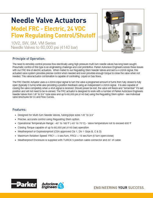
Principle of Operation:The need to remotely control process flow electrically using high pressure multi-turn needle valves has long been sought.Pneumatic control of this type is an engineering challenge and cost prohibitive. Parker Autoclave Engineers solves these issues with our FRC line of electric actuators. When mated to our Regulating Stem Needle Valves and sent a 4-20mA signal, this actuated valve system provides precise control when needed and even provides enough torque to close the valve when not needed. This valve/actuator combination is capable of controlling Liquid or Gas flows.The FRC Electric Actuator uses a 4-20mA input signal to turn the valve a programed amount of turns from fully closed to fully open (typically 5 turns) while also providing a position feedback using an independent 4-20mA signal. It is also capable ofclosing the valve completely when a 4mA signal is received. Should power be lost, the valve will freeze and “remember” it’s last position and will not need to be re-zeroed. The FRC actuator is designed to work with a number of Parker Autoclave Engineers Needle Valves from 1/8" to 3/4" tube sizes and up to 60,000 psi (4140 bar) using the Regulating Stem option - see individual valve brochures for Cv and Flow Curves.Features:• Designed for Multi-turn Needle Valves, tubing/pipe sizes 1/8" to 3/4"• Precise, accurate control using Regulating Stem option.• Operational Temperature Range: -40° to 160°F (-40° to 70°C) - Valve temperature not to exceed 600°F • Closing Torque capable of up to 60,000 psi (4140 bar) operation• Weatherproof or Explosionproof (CSA approved Cls 1, Div 1 Grps B, C & D)• Maximum Rotation Speed: FRC1 = 4 sec/turn, FRC2 = 15 sec/turn (5 turn open/close)• Weatherproof Enclosure is supplied with TURCK 5 position cable connector and 20’ of cableNeedle Valve ActuatorsModel FRC - Electric, 24 VDCFlow Regulating Control/Shutoff10V2, SW, SM, VM SeriesNeedle Valves to 60,000 psi (4140 bar)2Needle Valve Actuator: Model FRC - Electric Flow Regulating Control/Shutoff 02-9336BE 0523Specifications and Ordering Guide:Electric ActuatorElectrical Specifications:• Electrical Input: 24VDC only, 72 Watt maximum • Control Input: 4-20mA• Position Feedback: Independent 4-20mA • Position Detection: Hall Sensors • Motor: BLDC brushless DC motorMechanical Specifications:• Standard Enclosure - EPD Coated NEMA 4/IP65 Equivalent • Optional Anodized Aluminum Explosion-Proof Enclosure, Nema 8/IP67, CSA Approved for Class 1, Division 1, Groups B, C, D / T6 Areas (*Group B is suitable for Hydrogen)• 500+ Positions per turn (+/- 0.25° Position Accuracy), 3243 Actuator Positions over Full Span• Maximum Rotation Speed: #1 Actuator = 4 sec/turn (5 turn open/close), #2 Actuator (high torque) = 15 sec/turn (5 turn open/close)• Actuator Operating Temperature -40°(-40°C) to160°F(70°C), Valve Temperature not to exceed 600°F • Actuator life Expectancy: 250,000 cycles • Gears and Bearings are Lifetime Lubricated• 20 ft. cable included with 6 pin/5 wire connector (FRC1 and FRC2 Weatherproof version only)• Wiring Terminal, Maximum Wire Size: 18 Gauge (To Terminate larger gauge wire, see Option Code XPFL below)Position on Powerloss:• Remembers Last Position•Reseats Valve if Current is Between 3.0 and 4.16mAOrdering Guide:(reference individual Valve Series brochure for exact valve detail)20SM9882-FRC2XTG = 20SM Series Needle Valve, 20,000 psi MAWP , 9/16” MP Cone and Thread, 2-way Angle/Replaceable Seat Valve, Flow Regulating On/Off Explosion Proof Actuator/High Torque, PTFE Glass packing to 600°F max.Note: Actuators can be rotated to any one of four compass locations. (requires zeroing function (re-seating).Dimensional Information:3 Needle Valve Actuator: Model FRC - Electric Flow Regulating Control/Shutoff 02-9336BE 0523Dimensional Information:4Needle Valve Actuator: Model FRC - Electric Flow Regulating Control/Shutoff 02-9336BE 0523Dimensional Information:5 Needle Valve Actuator: Model FRC - Electric Flow Regulating Control/Shutoff 02-9336BE 0523Dimensional Information:1/2" NPT (Nipple)6Needle Valve Actuator: Model FRC - Electric Flow Regulating Control/Shutoff 02-9336BE 0523Parker’s Motion & Control TechnologiesAt Parker, we’re guided by a relentless drive to help our customers become more productive and achieve higher levels of profitability by engineeringthe best systems for their requirements. It means looking at customer applications from many angles to find new ways to create value. Whateverthe motion and control technology need, Parker has the experience, breadth of product and global reach to consistently deliver. No company knows more about motion and control technology than Parker. For further information call 1-800-C-Parker.7Needle Valve Actuator: Model FRC - Electric Flow Regulating Control/Shutoff 02-9336BE 0523! CAUTION !Do not mix or interchange component parts or tubing with those of other manufacturers. Doing so is unsafe and will void warranty.Parker Autoclave Engineers Valves, Fittings, and Tools are not designed to interface with common commercial instrument tubing and are designed to only connect with tubing manufactured toParker Autoclave Engineers AES specifications. Failure to do so is unsafe and will void warranty.Offer of SaleThe items described in this document are available for sale by Parker Hannifin Corporation, its subsidiaries or its authorized distributors. Any sale contract entered by Parker will begoverned by the provisions stated in Parker's standard terms and conditions of sale (copy available upon request).©2023 Parker Hannifin Corporation | Autoclave Engineers is a registered trademark of the Parker Hannifin Corporation Literature #: 02-9336BE May 2023ISO-9001 CertifiedInstrumentation Products Division Autoclave Engineers Operation 8325 Hessinger Drive Erie, PA 16509-4679Tel: 814 860 5700Fax: 814 860 5811/ipdInstrumentation Products Division Division Headquarters 1005 A Cleaner WayHuntsville, AL 35805 USA Tel: 256 881 2040Fax: 256 881 5072WARNINGFAILURE, IMPROPER SELECTION OR IMPROPER USE OF THE PRODUCTS AND/OR SYSTEMS DESCRIBED HEREIN OR RELATED ITEMS CAN CAUSE DEATH,PERSONAL INJURY AND PROPERTY DAMAGE.This document and other information from Parker Hannifin Corporation, its subsidiaries and authorized distributors provide product and/or system options for further investigation by users having technical expertise. It is important that you analyze all aspects of your application and review the information concerning the product or system in the current product catalog. Due to the variety of operating conditions and applications for these products or systems, the user, through its own analysis and testing, is solely responsible for making the final selection of the products and systems and assuring that all performance, safety and warning requirements of the application are met. The prod-ucts described herein, including without limitation, product features, specifications, designs, availability and pricing, are subject to change by Parker Hannifin Corporation and its subsidiaries at any time without notice.Needle Valve Actuator: Model FRC - Electric Flow Regulating Control/Shutoff 02-9336BE 0523Parker WorldwideNorth AmericaUSA – Corporate, Cleveland, OH Tel: +1 256 896 3000USA – IPD, Huntsville, AL Tel: +1 256 881 2040*****************USA – IPD, (Autoclave), Erie, PA Tel: +1 814 860 5700*******************CA – Canada, Grimsby, Ontario Tel +1 905-945-2274*********************South AmericaAR – Argentina, Buenos Aires Tel: +54 3327 44 4129 ******************BR – Brazil, Diadema, SP Diadema, SPTel: +55 11 4360 6700******************CL – Chile, Santiago Tel: +56 (0) 2 2303 9640******************MX – Mexico, Toluca Tel: +52 722 275 4200*******************Asia PacificAU – Australia, Dandenong Tel: +61 (0)2 9842 5150******************************CN – China, Shanghai Tel: +86 21 2899 5000*****************************HK – Hong Kong Tel: +852 2428 8008IN – India, MumbaiTel: +91 22 6513 7081-85ID – Indonesia, Tangerang Tel: +62 2977 7900********************JP – Japan, Tokyo Tel: +(81) 3 6365 4020******************KR – South Korea, Seoul Tel: +82 2 559 0400*******************MY – Malaysia, Selangor Tel: +603 784 90 800*******************SG – Singapore,Tel: +65 6887 6300*******************TH – Thailand, Bangkok Tel: +66 2 186 7000*********************TW – Taiwan, Taipei Tel: +886 2 2298 8987*************************VN – Vietnam, Hochi Minh City Tel: +848 382 508 56**********************Europe, Middle East, AfricaAE – UAE, Dubai Tel: +971 4 812 7100********************AT – Austria, Wiener Neustadt Tel: +43 (0)2622 23501-0*************************AT – Eastern Europe, Wiener Neustadt Tel: +43 (0)2622 23501 900****************************AZ – Azerbaijan, Baku Tel: +994 50 2233 458****************************BE/LU – Belgium, Nivelles Tel: +32 (0)67 280 900*************************BG – Bulgaria, Sofia Tel: +359 2 980 1344**************************BY – Belarus, Minsk Tel: +48 (0)22 573 24 00*************************CH – Switzerland, Etoy Tel: +41 (0) 21 821 87 00*****************************CZ – Czech Republic, Klecany Tel: +420 284 083 111*******************************DE – Germany, Kaarst Tel: +49 (0)2131 4016 0*************************DK – Denmark, Ballerup Tel: +45 43 56 04 00*************************ES – Spain, Madrid Tel: +34 902 33 00 01***********************FI – Finland, VantaaTel: +358 (0)20 753 2500*************************FR – France, Contamine s/Arve Tel: +33 (0)4 50 25 80 25************************GR – Greece, Athens Tel: +30 210 933 6450************************HU – Hungary, Budapest Tel: +36 223 885 470*************************IE – Ireland, DublinTel: +353 (0)1 466 6370*************************IT – Italy, Corsico (Ml)Tel: +39 02 45 19 21***********************KZ – Kazakhstan, Almaty Tel: +7 7273 561 000****************************NL – The Netherlands, Oldenzaal Tel: +31 (0)541 585 000********************NO – Norway, Stavanger Tel: +47 66 75 34 00************************PL – Poland, Warsaw Tel: +48 (0)22 573 24 00************************PT – Portugal, Leca da Palmeira Tel: +351 22 999 7360**************************RO – Romania, Bucharest Tel: +40 21 252 1382*************************RU – Russia, Moscow Tel: +7 495 645-2156************************SE – Sweden, Spånga Tel: +46 (0)8 59 79 50 00************************SK – Slovakia, Banská Bystrica Tel: +421 484 162 252**************************SL – Slovenia, Novo Mesto Tel: +386 7 337 6650**************************TR – Turkey, Istanbul Tel: +90 216 4997081************************UA – Ukraine, KievTel: +48 (0)22 573 24 00*************************UK – United Kingdom, Warwick Tel: +44 (0)1926 317 878********************ZA – South Africa, Kempton Park Tel: +27 (0)11 961 0700*****************************。
电动蝶阀使用说明书(中英文)

电动蝶阀使用说明书(中英文)电动蝶阀Electric Butterfly Valve使用说明书Operation Manual一、用途Ⅰ.Application本系列蝶阀适用于冶金、矿山、建材、石化、造纸、纺织等行业的工业管道中。
它对气体半流体等管道中的介质按不同的信号,改变其流量的大小,从而达到自动调整风量,实现自动控制。
体阀采用优质钢板焊接结构,具有传动轻巧灵活,密封性能好,开闭时间短,切断速度快,能可靠的杜绝事故的发生。
This series butterfly valve is suitable to use in the industry pipe of metallurgical, ore building material. Paper textile and so on, Accord to the different signal in the pipes of the gas half fluid medium. Change the flow volume, and adjust the fan volume automatically. It can realize automatic control. The valve is used good welding structure. It is characterized by light, nimble good sealing, short open time, fast speed broken and dependable.二、结构及工作原理Ⅱ.The structure and Working principle1、电动蝶阀由电动执行机构和蝶阀组成,有关电动执行机构作用原理,使用维护等参阅电动执行机构说明书。
1、The electric butterfly valve is composed of electric executestructure and butter fly valve. The relative electric execute. Working principle and main is refer to the operation manual of electric executor.2、电动蝶阀按作业方式可分为电开式和电关式两种。
3810L电动执行器使用说明中英文.

3810L电动执行器使用说明书3810L Electric Actuator Instructions目录Table of Contents1. 产品概述Product Overview2. 主要技术参数The main technical parameters3. 产品型号规格Product Specification4、结构与原理The structure and principles5、安装Installation6、调整Adjusting7、外形尺寸Dimension8、配套支架The supporting bracket9、故障和解决办法fault and solutions10 、订货须知Ordering Information 11 、安全使用注意事项Safety Precautions使用本执行器时,请先认真阅读和理解本说明书,通过正确的使用和维护,充分发挥其效能。
When using this actuator, please read and understand the present specification, by the proper use and maintenance, full play to its effectiveness.1 产品概述Product Overview3810L 系列直行程电子式电动执行器有以220V 交流单相电源和380V 三相交流电源两种驱动电源的机型,接受来自调节器控制信号( D C 4 ~ 20m A 或DC 1 ~ 5V ),实现预定直线往复运动的新型执行器。
本系列执行器被用作调节阀的执行机构时,几乎具备了调节阀本身所要求的各种动作变换功能以及阀开度信号功能和手动功能。
因此被广泛应于发电、冶金、石化、轻工及环保等工业部门。
主要特点:main feature:1.1执行器设计有伺服系统(无需另配伺服放大器),只需接入DC4〜20mA (或D C1~5V )信号和对应的电源即可工作。
江苏常州ZB型阀门中英文说明书
ZB 型阀门电动装置使 用 说 明 书OPERATION MANUAL FOR TYPE ZB ELECTRIC VALVE AVTUATORS中华人民共和国常州电站辅机总厂有限公司CHANGZHOU POWER STATION AUXILIARY EQUIPMENT WORKS, Ltd.THE PEOPLE`S REPUBLIC OF CHINA一概述General DescriptionZB系列阀门电动装置为双位阀电驱动装置,适用于阀瓣做直线运动的阀门,如截止阀、闸阀、节流阀、隔膜阀等。
与二级减速装置组合后,也可用于阀瓣做旋转运动的阀门,如球阀、蝶阀等。
Series ZB Electric Valve Actuators are designed for two position valves and suitable for valves which stems move linearly, such as globe valve, gate valve, throttle valve and diaphragm valve. Combined with a two stage reducer, they can also be used in operating valves which stems move rotating, such as ball valve and butterfly valve.二型号表示方法Type Representation输出轴最大转圈数:用阿拉伯数字表示。
Max.turnsof output shaft, expressed by Arabic figures.r/min 表示。
Rated speedT为推力型(ISO5210),无字母为转矩型。
mode, expressed by letter. Letter T representsN·m的1/10(用阿拉伯数字表示)Rated torque,expressed by Arabic figures(× 10 N·m)Type of products, suitable for gate valve, globe valve,diaphragm valve etc.三工作环境和主要技术数据Service Environment and Main Technical Data1.电机电压:380V,50Hz(特殊订货可380V~660V,50Hz,60Hz)控制电压:220V, 50Hz(特殊订货可220V~240V,50Hz,60Hz)Power voltage: 380V,50Hz(380V~660V,50Hz,60Hz for special order)Control voltage: 220V,50Hz(220V~240V,50Hz,60Hz for special order)2.工作环境:Service environment:2.1.1 环境温度:-20~60℃Environmental temperature: -20~60℃2.1.2 环境相对湿度:≤90%(25℃时)Permitted relative humidity: no more than 90%(25℃)2.1.3 工作环境不含有腐蚀性、易燃、易爆的介质;No corrosive, flammable and explosive media.2.1.4 防护等级 IP55(特殊订货可达IP68)Protection IP55 (IP68 for special order )3. 短时工作制,时间定额为10分钟;Short-time duty, rated time 10 minutes.4. 规格和主要技术数据见表1。
自动阀门 VALVES The Series WE01说明书
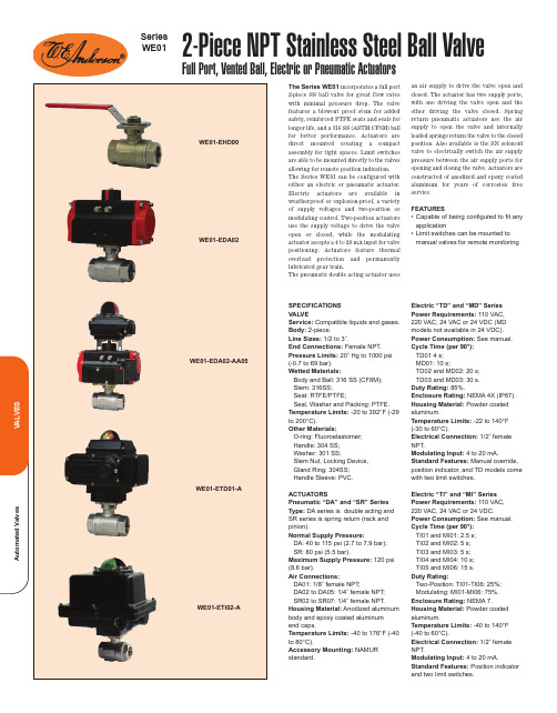
The Series WE01incorporates a full port2-piece SS ball valve for great flow rateswith minimal pressure drop. The valvefeatures a blowout proof stem for addedsafety, reinforced PTFE seats and seals forlonger life, and a 316 SS (ASTM CF8M) ballfor better performance. Actuators aredirect mounted creating a compactassembly for tight spaces. Limit switchesare able to be mounted directly to the valvesallowing for remote position indication.The Series WE01 can be configured witheither an electric or pneumatic actuator.Electric actuators are available inweatherproof or explosion-proof, a varietyof supply voltages and two-position ormodulating control. Two-position actuatorsuse the supply voltage to drive the valveopen or closed, while the modulatingactuator accepts a 4 to 20 mA input for valvepositioning. Actuators feature thermaloverload protection and permanentlylubricated gear train.The pneumatic double acting actuator usesan air supply to drive the valve open andclosed. The actuator has two supply ports,with one driving the valve open and theother driving the valve closed. Springreturn pneumatic actuators use the airsupply to open the valve and internallyloaded springs return the valve to the closedposition. Also available is the SN solenoidvalve to electrically switch the air supplypressure between the air supply ports foropening and closing the valve. Actuators areconstructed of anodized and epoxy coatedaluminum for years of corrosion freeservice.FEATURES•Capable of being configured to fit anyapplication• Limit switches can be mounted tomanual valves for remote monitoringSPECIFICATIONSVALVEService:Compatible liquids and gases.Body:2-piece.Line Sizes:1/2 to 3˝.End Connections:Female NPT.Pressure Limits:20˝ Hg to 1000 psi(-0.7 to 69 bar).Wetted Materials:Body and Ball: 316 SS (CF8M);Stem: 316SS;Seat: RTFE/PTFE;Seal, Washer and Packing: PTFE.Temperature Limits:-20 to 392°F (-29to 200°C).Other Materials:O-ring: Fluoroelastomer;Handle: 304 SS;Washer: 301 SS;Stem Nut, Locking Device,Gland Ring: 304SS;Handle Sleeve: PVC.ACTUATORSPneumatic “DA” and “SR” SeriesType:DA series is double acting andSR series is spring return (rack andpinion).Normal Supply Pressure:DA: 40 to 115 psi (2.7 to 7.9 bar);SR: 80 psi (5.5 bar).Maximum Supply Pressure:120 psi(8.6 bar).Air Connections:DA01: 1/8˝ female NPT;DA02 to DA05: 1/4˝ female NPT;SR02 to SR07: 1/4˝ female NPT.Housing Material:Anodized aluminumbody and epoxy coated aluminumend caps.Temperature Limits:-40 to 176°F (-40to 80°C).Accessory Mounting:NAMURstandard.Electric “TD” and “MD” SeriesPower Requirements: 110 VAC,220 VAC, 24 VAC or 24 VDC (MDmodels not available in 24 VDC).Power Consumption:See manual.Cycle Time (per 90°):TD01 4 s;MD01: 10 s;TD02 and MD02: 20 s;TD03 and MD03: 30 s.Duty Rating:85%.Enclosure Rating:NEMA 4X (IP67).Housing Material:Powder coatedaluminum.Temperature Limits: -22 to 140°F(-30 to 60°C).Electrical Connection:1/2˝ femaleNPT.Modulating Input:4 to 20 mA.Standard Features:Manual override,position indicator, and TD models comewith two limit switches.Electric “TI” and “MI” SeriesPower Requirements:110 VAC,220 VAC, 24 VAC or 24 VDC.Power Consumption:See manual.Cycle Time (per 90°):TI01 and MI01: 2.5 s;TI02 and MI02: 5 s;TI03 and MI03: 5 s;TI04 and MI04: 10 s;TI05 and MI06: 15 s.Duty Rating:Two-Position: TI01-TI06: 25%;Modulating: MI01-MI06: 75%.Enclosure Rating:NEMA 7.Housing Material:Powder coatedaluminum.Temperature Limits:-40 to 140°F(-40 to 60°C).Electrical Connection:1/2˝ femaleNPT.Modulating Input:4 to 20 mA.Standard Features:Position indicatorand two limit switches.2-Piece NPT Stainless Steel Ball ValveFull Port, Vented Ball, Electric or Pneumatic ActuatorsSeriesWE01ACCESSORIESR2-2120,Air RegulatorAFR2-2, Instrument Air Filter RegulatorVB-01, Volume Booster。
执行器使用英文说明书
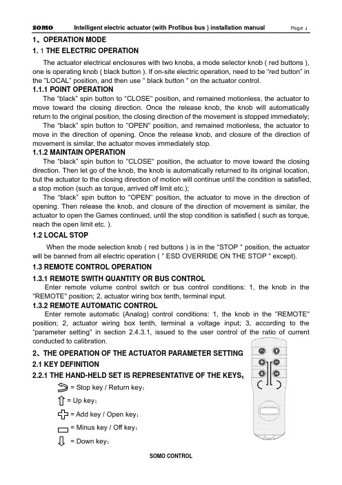
1、OPERATION MODE1. 1 THE ELECTRIC OPERATIONThe actuator electrical enclosures with two knobs, a mode selector knob ( red buttons ), one is operating knob ( black button ). If on-site electric operation, need to be “red button” in the "LOCAL” position, and then use " black button " on the actuator control.1.1.1 POINT OPERATIONThe “black” spin button to "CLOSE" position, and remained motionless, the actuator to move toward the closing direction. Once the release knob, the knob will automatically return to the original position, the closing direction of the movement is stopped immediately;The “black” spin button to "OPEN" position, and remained motionless, the actuator to move in the direction of opening. Once the release knob, and closure of the direction of movement is similar, the actuator moves immediately stop.1.1.2 MAINTAIN OPERATIONThe “black” spin button to "CLOSE" position, the actuator to move toward the closing direction. Then let go of the knob, the knob is automatically returned to its original location, but the actuator to the closing direction of motion will continue until the condition is satisfied, a stop motion (such as torque, arrived off limit etc.);The “black” spin button to "OPEN" position, the actuator to move in the direction of opening. Then release the knob, and closure of the direction of movement is similar, the actuator to open the Games continued, until the stop condition is satisfied ( such as torque, reach the open limit etc. ).1.2 LOCAL STOPWhen the mode selection knob ( red buttons ) is in the "STOP " position, the actuator will be banned from all electric operation ( " ESD OVERRIDE ON THE STOP " except).1.3 REMOTE CONTROL OPERATION1.3.1REMOTE SWITH QUANTITY OR BUS CONTROLEnter remote volume control switch or bus control conditions: 1, the knob in the "REMOTE" position; 2, actuator wiring box tenth, terminal input.1.3.2 REMOTE AUTOMATIC CONTROLEnter remote automatic (Analog) control conditions: 1, the knob in the "REMOTE" position; 2, actuator wiring box tenth, terminal a voltage input; 3, according to the “parameter setting" in section 2.4.3.1, issued to the user control of the ratio of currentconducted to calibration.2、THE OPERATION OF THE ACTUATOR PARAMETER SETTING2.1 KEY DEFINITION2.2.1THE HAND-HELD SET IS REPRESENTATIVE OF THE KEYS:= Stop key / Return key;= Up key;= Add key / Open key;= Minus key / Off key;= Down key;= Confirm key;2.2.2MODE BUTTON REPRESENTS THE KEY:Confirm key: mode button from the "STOP" - > “LOCAL" position, hereinafter referred to as the "Confirm key;Return key: mode button from the "STOP" - > “REMOTE" position, hereinafter referred to as the "return key;2.2.3THE OPERATION BUTTON REPRESENTS THE KEYDown key: the operating button - > " CLOSE" position, hereinafter referred to as the "Down key;Add key: the operating button - > " OPEN" position, hereinafter referred to as the "Add key;2.2 LCDThe actuator is equipped with a bitmap type liquid crystal display. Its layout is the region Ⅰ,Ⅱ,Ⅲ zone.I zone for valve position display area, the valve opening position percentage in the form of real-time display the current valve position value;II zone for the control of display area;III zone for running state and alarm information display area ( see behind the " five, alarm information." );When entering the working parameter setting menu, the LCD screen will use a unified region Ⅰ,Ⅱ,Ⅲ zone.2.3 POWER ON OR RESET2.3.1 POWER ON SELF TEST SYSTEMThe actuator after power on, the actuator control system based on instruction, program area, data region and a A/D conversion function in self. If the test were normal, LCD liquid crystal display valve position display area shows the current valve opening position percentage, alarm area contents are cleared. If the self-test one is not normal, warning zone will always show the abnormal code, the control system not to accept any operation, pending.The actuator power after initialization, the liquid crystal display screen in large font to display the percentage of valve opening. In the valve position limit position, the valve opening display simulation butterfly valve graphical display ( see below ).2.3.2 SYSTEM RESETIn any case, the mode button on the " STOP" position, the operation button is placed on the " CLOSE" position and maintain 5S above the clock, until the liquid crystal screen above the lighted indicator lights, and then release the operation knob away from the "CLOSE" position, the control system reset.2.4 WORKING PARAMETER SETTINGNote 1: in the menu operation, if the user in 1 minutes without key operation, display will automatically return to a setting screen. In addition, in the menu operation, should use the return key to exit the setup screen, before the motor rotates at a setting screen when the valve opening position.Note 2: in the menu operation, first display settings or first display setting value is set after the last stored value, the user can use this feature to view previously set value.2.4.1ENTER MENUThe mode button on the “LOCAL" position, according to the hand-held set on 1, 2, 5, 6 keys of any key can enter the working set menu. Or will the mode button on the " STOP" position, the operation button is placed on the " OPEN" position and maintain 3S above the clock, control system into the working set main menu.Note: In order to behind the narrative and display with convenient, " [ ] " the representationof the selected menu, in the liquid crystal screen menu display, the selected item is to reverse display mode ( i.e. black white ) indicating the cursor position; not the selected itemin a conventional manner ( i.e. black text on a white background ).2.4.2 BASIC SETTINGS MENUIn [ 1 ] on the menu, with a "Up key " or " Down key " to select the desired item, then press " Confirm key ", show will enter the corresponding menu as shown above. Basic settings [ 2 ] on the menu of 4 options, namely, " CHANGE CLOSE DIRECTION ", " LOCAL CONTROL MODE ", " ACCEPT VALVE LIMIT CLOSED VALVE LIMIT OPEN " and " ACCEPT ".2.4.2.1 CHANGE CLOSE DIRECTIONIn [ 2 ] on the menu " CHANGE CLOSE DIRECTION ", the selected item, the line of the right will show a previously set value ( " CLOCKWISE " or " COUNTER CLOCKWISE " ). Click the " Return key" to return to the previous menu, does not alter the previously set value. Users can use these characteristics to query a previously set value ( following similar, no longer has the ). Use the "Add key ", " Minus key " can make the setting value in " CLOCKWISE " and " COUNTER CLOCKWISE " switching between. Use the "Confirm key " save the selected set value.2.4.2.2 LOCAL CONTROLIn [ 2 ] on the menu " LOCAL CONTROL MODE ", the selected item, the line of the right will show a previously set value ( " INCHING " or " MAINTAIN " ). Use the "Add key ", " Minus key " can make the setting value in " INCHING " and " MAINTAIN " switching between. Use the "Confirm key " save the selected set value.2.4.2.3 ACCEPT VALVE LIMIT CLOSEDLimit set order is unlimited, the user can set off again on a set, can also open a set off again.In [ 2 ] on the menu, " ACCEPT VALVE LIMIT CLOSED " selected item, the rows of the right will show the current absolute encoder output current location for thousands of ratio of (0~ 1000). Manual mode will be available to the valve rotation limit; can also be mode button on the " LOCAL " position, according to the hand-held set is Open key/Off key or by operating the button with means of the electric motor valve rotating to limit at. Click the " Confirm key ", LCD screen above the red indicator light flashing 2 exhibit of lanterns before, said actuator has the position calibration for clearance limit. According to the " Confirm key " to " Return key " before, do not set off the limit, and return to the previous menu.2.4.2.4 ACCEPT VALVE LIMIT OPENIn [ 2 ] on the menu, " ACCEPT VALVE LIMIT OPEN " selected item, the rows of the rightwill show the current absolute encoder output current location for thousands of ratio of (0~1000). Available manually valve rotates to the open limit; can also be mode button on the "LOCAL" position, according to the hand setting device on a "Open key/Off key " or by the operating knob with means of the electric motor valve rotating to open limit position. Click the " Confirm key ", when the liquid crystal screen above the green indicator exhibit of lanterns flashing 2 after light, said actuator has the position calibration for open limit. According to the " Confirm key " to " Return key " before, do not set the open limit, and return to the previous menu.Note 1: 1000 ratio 0 and 1000 respectively for absolute encoder minimum code value and the maximum code value, the two is the coincidence. Open, close to set the limit of the whole trip can after this point, but should guarantee the full travel beyond that represent the range of absolute encoder. Note 2: if the set limit is set at one end and another end limit, should not withdraw from the original set, and run to the other end of the limiting office, then enters the other end limit setting item for confirmation, otherwise there will be a " blocking " warning error.2.4.2.5 CHANGE THE LCD DISPLAYIn [ 3 ] on the menu, with a "Up key " or " Down key " selected " CHANGE THE LCD DISPLAY", the bank's right will show a previously set value ( " INVERT " or " POSITIVE " ). Use the "Add key ", " Minus key " to select the desired value, use the "Confirm key " save the selected revision.2.4.3 SECOND SETUPIn [1] on the menu, selected " SECOND SETUP" and press "confirm " [ 3 ] into the menu. As shown in the following illustration.2.4.3.1 4-20mA OF ACC. CALIBRATIONIn [ 3 ] on the menu, with a "Up key " or " Down key " selected " 4-20mA OF ACC. CALIBRATION" and press "Confirm key " [ 4 ] on screen display menu content.When a user sends the actuator 4mA~ 20mA current and actuator previous calibration value is different, use this function is issued to the user 's current recalibrated, causes the actuator and the user's 4mA~ 20mA current transmission device with the same measure, in order to improve the accuracy of the actuator control system.In order to describe convenience, defines 4mA signal low-end (referred to as low signal ), 20mA signals for high-end (referred to as the high letter).CALIBRATE 4mA FOR ACC in [ 4 ]: on the menu, with a "Down key " selected " CALIBRATE 4mA FOR ACC", the bank's right will show the actuator to collect the control current value ( mA ); the user can send the control current to the actuator end of the signal, and when the current is stable after according to the " Confirm key " save the collected current value.CALIBRATE 20mA FOR ACC in [ 4 ]: on the menu, with a "Down key " selected " CALIBRATE 20mA FOR ACC", the bank's right will show the actuator to collect the control current value ( mA ); the user can send the control current to the actuator end signal, and to the current stability according to the " Confirm key " save the current value.At any time the user can control the current calibration menu to query the user sends the current value, but in the control current signal without calibration, inquires into the value is not accurate.2.4.3.2 POSITIONING CONTROL SETUPIn [ 3 ] on the menu, with a "Up key " or " Down key " select " POSITIONING CONTROL SETUP" and click " Confirm key " [ 5 ] on screen display menu content.2.4.3.2.1 DEADBAND ADJUSTMENTDead meaning: the functions of the remote automatic control method. In this mode, the actuator according to the control current to calculate the user wishes to valve position value, then the value and the current valve position values are compared, and if the absolute value of the difference is greater than the zone value, the actuator to action, so that the current valve valve position close to the goal orientation. If the current valve position and the user wants the valve position of the absolute value of the difference in the dead zone range, then the actuator stop motion. Set proper dead-time prevents the actuator in a valve position oscillation.In [ 5 ] on the menu, with a "Down key " selected " DEADBAND ADJUSTMENT " item, the line of the right will show a previously set value ( 0.1%~9.9% ) or " SELF ADAPTING ". The user can use the " Add key ", " Minus key " to change the deadband values. Select the desired deadband value, using " Confirm key " to save your changes.2.4.3.2.2 POLARITY FOR ACCPOLARITY FOR ACC: in current control mode, the lower end of the signal ( 4mA current)Note corresponding to the valve opening position value.In [ 5 ] on the menu, with a "Down key " selected " POLARITY FOR ACC", the bank's right will show a previously set value " 4mA = CLOSED " or " 4mA = OPEN ". The user can use the " Add key ", " Minus key " to change the selection. Select the desired value, using the " Confirm key " to save your changes.Note: the current and low current corresponding to the valve opening position values are mutually exclusive. For example, when setting the low-side current corresponding valve position switch, current automatic corresponding valves full open. Conversely, low signal valve set corresponding valve fully open, the high-end automatic current corresponding to the valve position switch.2.4.3.2.3 ACTION ON LOSS SIGNALLost letter: when the actuator is in the remote automatic control mode, and the control current is less than the low current 1/2, actuators that control signal is lost, referred to as the lost letter.ACTION ON LOSS SIGNAL:ACTION ON LOSS SIGNAL defined in the event of lost letter when the actuator should run into position. The "STAY UP ", " CLOSED ", " OPEN " 3 selectable values. The " STAY UP " refers to remain in situ.In [ 5 ] on the menu, with a "Down key " ACTION ON LOSS SIGNAL " selected " item, the bank's right will show a previously set value ( " STAY UP " or " CLOSED " or " OPEN " ). Use the "Add key ", " Minus key " to select the desired value, use the "Confirm key " save the selected revision.2.4.3.2.4 BRAKE TIME WITH TURN IN REVERSEBRAKE TIME WITH TURN IN REVERSE refers to the movement of the actuator to the target position, and then a short reverse rotation, to compensate for actuator motion inertia, to improve the control precision of the objective.In [ 5 ] on the menu, with a "Down key " " BRAKE TIME WITH TURN IN selected REVERSE " item, the bank's right will show the previous set of actuators rotate in reverse time value ( mS ). Use the "Add key ", " Minus key " in 0~ 50mS time range to select the desired value ( 0mS said without brake ), using " Confirm key " to save your changes.2.4.3.3 ESD SETUPIn [ 3 ] on the menu, with a "Up key " or " Down key " select the "ESD SETUP" and click " Confirm key " [ 6 ] on screen display menu content. : select “ESD SETUP” and " Add key ", according to the " Minus key " will cause the system reset, is a normal phenomenon ( the factory when tested with ).2.4.3.3.1 ESD ACTIONESD: refers to emergency situations (i.e., the actuator control signal terminal to detect ESD ESD appear on the effective signal) actuator which actions to perform. There are 3 kinds of ESD action: " OPEN ", " CLOSED " and " STOP ".In [ 6 ] on the menu, with a "Up key " or " Down key " selected " ESD ACTION " item, the line of the right will show a previously set value ( " CLOSED " or " OPEN " or " STOP " ). Use the "Add key ", " Minus key " to select the desired value, use the "Confirm key " save the selected revision.2.4.3.3.2 ESD ACTION WHEN ESD SIGNAL ISThe actuator ESD control signal terminal input signal can be two levels: no voltage signal is called the low level, a voltage signal is called the high level.In [ 6 ] on the menu, with a "Down key " " ESD ACTION WHEN ESD SIGNAL selectedIS " item, the bank's right will show a previously set value ( " ABSENT " or " PRESENT " ). Use the "Add key ", " Minus key " to select the desired value, use the "Confirm key " save the selected revision.2.4.3.3.3 ESD OVERRIDE ON THERMALESD OVERRIDE ON THERMAL refers to " MOT.OVERTHERMAL " even if the alarm will execute ESD control action, otherwise, to stop the implementation of ESD control action.In [ 6 ] on the menu, with a "Up key " or " Down key " ESD OVERRIDE ON THERMAL " selected " item, the bank's right will show a previously set value ( " YES " or " NO " ). Use the " Add key ", " Minus key " to select the desired value, use the "Confirm key " save the selected revision.2.4.3.3.4 ESD OVERRIDE ON THE STOPESD OVERRIDE ON THE STOP refers to the even mode button in position "STOP" to perform ESD control action, otherwise, to stop the implementation of ESD control action.In [ 6 ] on the menu, with a "Up key " or " Down key " " ESD OVERRIDE ON THE STOP selected " item, the bank's right will show a previously set value ( " YES " or " NO " ). " Add key ", " Minus key " to select the desired value, use the" Confirm key " save the selected revision.2.4.3.4 NETWORK SETUPNot When the actuator through the Profibus field bus control, need to enter the items set in advance. If using a dual channel redundant configuration, need to set of channels and II channel address, or simply set Ⅰchannel address. Channel address refers to the bus control can be the main control system ( Master) and their identification code. e: This machine address reset, the actuator must first off, turn power can guarantee the normal work of the Profibus bus control.In [ 3 ] on the menu, with a "Up key " or " Down key " select the "NETWORK SETUP" and click " Confirm key " [ 7 ] on screen display menu content.2.4.3.5.1 SLAVE ADDRESS1In [ 7 ] on the menu, with a "Up key " or " Down key " select the "SLAVE ADDRESS1 " item, the right will be displayed before the set address value. Use the " Add key ", " Minus key" may be in the 1 to 126 range selection of the desired value, use the "Confirm key " tosave your changes.2.4.3.5.2 SLAVE ADDRESS2In [ 7 ] on the menu, with a "Up key " or " Down key " select the "SLAVE ADDRESS2 " item, the right will be displayed before the set address value. Use the " Add key ", " Minus key" may be in the 1 to 126 range selection of the desired value, use the "Confirm key " to save your changes.2.4.3.6 TWO-SPEED TIMERTWO-SPEED TIMER refers to the operation of the actuator is not continuous, but stop-and-go. This operation is directed to those in need in the valve to be opened or closed in the process of setting the clearance action. TWO-SPEED TIMER allows the actuator topulsating implementation of closing / opening action, so as to effectively increase the travel time, to prevent the hydraulic shock and fluid surge.If the choice is "DISABIE ", the operation of the actuator is normal continuous operation process; if you choose to "ENABLE", show [ 8 ] to enter the menu, according to the requirements of users on TWO-SPEED TIMER [ 8 ] on the menu in the child set.2.4.3.6.1 START POSITION IN OPENINGSTART POSITION IN OPENING refers to the actuator in the opening direction during the operation of opening “TWO-SPEED TIMER “start position. Use the "Add key ", " Minus key " in 0~100% opening range to select a desired value, use the "Confirm key " to save your changes.2.4.3.6.2 STOP POSITION IN OPENINGSTOP POSITION IN OPENING refers to the actuator in the opening direction of operation process termination " TWO-SPEED TIMER " end position. Use the "Add key ", " Minus key " in 0~ 100% opening range to select the desired value ( Note: STOP POSITION IN OPENING must be greater than START POSITION IN OPENING ), "Confirm key " to save your changes.2.4.3.7.3 PULSE ON IN OPENINGPULSE ON IN OPENING refers to the actuator in the opening direction of implementation of "TWO-SPEED TIMER " operation in each TWO-SPEED TIMER required during operation of the travel value. Use the "Add key ", " Minus key " in 2~ 100% opening range to select a desired value, use the "Confirm key " to save your changes.2.4.3.6.4 PULSE OFF IN OPENINGPULSE OFF IN OPENING refers to the actuator in the opening direction of implementation of "TWO-SPEED TIMER” operation in each discontinuous stop required during the time value. Use the "Add key ", “Minus key " in 1 to 255 seconds to select a desired value, use the "Confirm key " to save your changes.2.4.3.6.5 START POSITION IN CLOSINGSTART POSITION IN CLOSING refers to the actuator in the closing direction during the operation of opening “TWO-SPEED TIMER " start position. Use the "Add key ", " Minus key " in 0~100% opening range to select a desired value, use the "Confirm key " to save your changes.2.4.3.6.6 STOP POSITION IN CLOSINGSTOP POSITION IN CLOSING refers to the actuator in the closing direction in the running process of the termination of “TWO-SPEED TIMER " end position. Use the "Addkey ", " Minus key " in 0~100% opening range to select the desired value ( Note: STOP POSITION IN CLOSING must be less than START POSITION IN CLOSING ), "Confirm key " to save your changes.2.4.3.6.7 PULSE ON IN CLOSINGPULSE ON IN CLOSING refers to the actuator in the closing direction of implementation of "TWO-SPEED TIMER” operation in each intermittent operation required during operation of the travel value. Use the "Add key ", " Minus key " in 2~ 100% opening range to select a desired value, use the "Confirm key " to save your changes.2.4.3.6.8 PULSE OFF IN CLOSINGPULSE OFF IN CLOSING refers to the actuator in the closing direction of implementation of "TWO-SPEED TIMER” operation in each discontinuous stop required during the time value. Use the "Add key ", " Minus key " in 1 to 255 seconds to select a desired value, use the "Confirm key " to save your changes.2.4.4 POS.FDBK.CALThe actuator will current location to 4mA~20mA current delivered to the control room. When the user that sent 4mA ~20mA current is not on time, you can use this feature to be calibrated. In [ 1 ] on the menu, select " POS.FDBK.CAL" and press the " Confirm key " [ 9 ] into the menu. As shown in the following illustration.2.4.4.1 ADJUST 4MA FOR CPFIn [ 9 ] on the menu, with a "Up key " or " Down key " selected " ADJUST 4MA FOR CPF", the bank's right will show the previously set value. When the actuator force feedback 0% valve position corresponding to the current value (4mA), in order to offer user detection. If the 4mA current feedback is not accurate, the user can press the " Add key ", " Minus key " to adjust the actuator feedback current value, meet the requirements for " Confirm key " to save your changes.2.4.4.2 ADJUST 20MA FOR CPFIn [ 9 ] on the menu, with a "Up key " or " Down key " selected " ADJUST 20MA FOR CPF", the bank's right will show the previously set value. When the actuator force feedback 100% valve position corresponding to the current value ( 20mA ), in order to offer user detection. If the 20mA current feedback is not accurate, the user can press the " Add key ", " Minus key " to adjust the actuator feedback current value, meet the requirements for " Confirm key " to save your changes.2.4.4.3 POLARITY FOR CPFIn [ 9 ] on the menu, with a "Up key " or " Down key " select " POLARITY FOR CPF", the bank's right will show the previously set value ( 4MA=CLOSED or 4MA=OPEN ). The lower end of said feedback current value ( 4mA ) on behalf of the valve position value ( close / open ). Select the desired value, using the " Confirm key " to save your changes." POLARITY FOR CPF" is selected, the feedback current value ( 20mA ) on behalf of the valve position value is then determined, and the low-side current corresponding to the valve opening position values are mutually exclusive. Such as " POLARITY FOR CPF" selected " off ", is the current representative of the valve position value to "4MA= OPEN ".2.4.5 STATUS MENUIn [1], “SIGNAL VIEW menu, select " and press "Confirm key " [ 10 ] into the menu. As shown in the following illustration.2.4.5.1MODE BUTTON POSITIONIn [ 10 ] on the menu, with a "Up key " or " Down key " " POSITION OF THE SELECTOR KNOB selected " item, the right hand will display " mode button " location. The user can on the knob position query:When the mode knob ( red buttons ) in " STOP " position, [ 10 ] menu " POSITION OF THE SELECTOR KNOB" right "STOP " as normal, otherwise is not normal;When the mode knob ( red buttons ) in " LOCAL " position, [ 10 ] menu " POSITION OF THE SELECTOR KNOB" right "LOCAL " as normal, otherwise is not normal;When the mode knob ( red buttons ) in " REMOTE " position, [ 10 ] menu " POSITION OF THE SELECTOR KNOB" right "REMOTE " as normal, otherwise is not normal.Note: in this way, with the knob “return “operation does not play role.2.4.5.2THE OPERATION BUTTON POSITIONIn [ 10 ] on the menu, with a "Up key " or " Down key " " POSITION OF THE OPERATOR KNOB selected " item, the bank's right will show the mode button position. The user can on the knob position query:When the operation knob ( black button ) in " OPEN " position, [ 10 ] menu " POSITION OF THE OPERATOR KNOB" right "OPEN " as normal, otherwise is not normal;When the operation knob ( black button ) in " CLOSE " position, [ 10 ] menu " POSITION OF THE OPERATOR KNOB" right "CLOSE " as normal, otherwise is not normal;When the operation knob ( black button ) in " NOTHING " position, [ 10 ] menu " POSITION OF THE OPERATOR KNOB" right "NOTHING " as normal, otherwise is not normal.Note: in this entry, with the operation knob " down" operation or the query "CLOSE" position when the screen to display " CLOSE " after a second move to the next item.2.4.5.3 REMOTE OPEN SIGNAL APPEARIn [ 10 ] on the menu, select " REMOTE OPEN SIGNAL APPEAR", the right to display。
电动蝶阀使用说明书(中英文)
电动蝶阀Electric Butterfly Valve使用说明书Operation Manual一、用途Ⅰ.Application本系列蝶阀适用于冶金、矿山、建材、石化、造纸、纺织等行业的工业管道中。
它对气体半流体等管道中的介质按不同的信号,改变其流量的大小,从而达到自动调整风量,实现自动控制。
体阀采用优质钢板焊接结构,具有传动轻巧灵活,密封性能好,开闭时间短,切断速度快,能可靠的杜绝事故的发生。
This series butterfly valve is suitable to use in the industry pipe of metallurgical, ore building material. Paper textile and so on, Accord to the different signal in the pipes of the gas half fluid medium. Change the flow volume, and adjust the fan volume automatically. It can realize automatic control. The valve is used good welding structure. It is characterized by light, nimble good sealing, short open time, fast speed broken and dependable.二、结构及工作原理Ⅱ.The structure and Working principle1、电动蝶阀由电动执行机构和蝶阀组成,有关电动执行机构作用原理,使用维护等参阅电动执行机构说明书。
1、The electric butterfly valve is composed of electric execute structure and butter fly valve. The relative electric execute. Workingprinciple and main is refer to the operation manual of electric executor.2、电动蝶阀按作业方式可分为电开式和电关式两种。
KFD阀门控制箱中英文说明书
额定电流(安培)调节型适用电装型号Ⅲ配型、型Ⅳ配型结构形式:、抽屉式、小型R ated current (am pere)T A djusting typeZ W Q W JQ A pplicable type of electric fitting: for ZW type and Q W type.C X G Structure from : C draw er type, X sm all C ontrol cabinet of electric valve cabinetⅢⅣ抽屉式、挂壁式、、、阀门电动装置控制箱for JQ type draw er type, G wall type K F D —— 普 通 型 KFD 系 列 Common type KFD series一、概 述 Brief introduction该系列电动阀门控制箱,是与我厂生产的ZW 型、JQ 型及QW 型阀门电动装置配套使用的电控箱,用于控制阀门的开启和关闭,可用于现场单独控制或远方集中控制。
KFD 型电控箱有抽屉式和挂壁式两种结构。
This series of control cabinet of electric valve is the one to be used together with ZW type, JQ type and QW type electric valve actuator produced by our company and to control the opening and closing of valve. It can be used in site individual control or long-distance centralized control.KFD type electric control cabinet has two kinds of structure: drawer type and wall type. Designation型号表示方法 Designation二、技术数据 T echnical data1、电源:380V 50Hz 三相四线制(特殊要求,另见)2、工作环境:(1)环境温度:—20℃~+60℃ (2)相对湿度:≤85%(20℃时)(3)周围不含强腐蚀性、易燃易爆介质及导电尘埃。
电动执行器 quarter turn ER-10-20-35 ER 60-100 技术手册说明书

1/2ER 10-20-35ER 60-100Product features• Torque range Md = 10-20-35-60-100 Nm• Limit switches4 adjustable limit switches 5A (2x int. + 2x ext.)• Heating resistance ER 10 + 20 7 W, ER 35 + 100 10 W controlled • Duty rating ED = 50%• ProtectionIP66• Temperature range -10ºC ÷ 55ºC (Fail Safe: -10ºC ÷ 40ºC)• Electronic torque limiter, failure feedback relayConstructionDimensionsEmergency manual override:In case of an electric supply failure, it is possible to operate the actuator manually:- Turn the clutch knob «13» to position MAN and hold it in position (reduction «7» disengaged)- Turn the outgoing drive shaft of the actuator with the handlever (ER10-20) or a adjusting spanner (ER35-100).- In order to re-engage the reduction, release the clutch knob.Power supply: Connector 3P+G DIN436502/2ER_1711© 2017 InterApp AG, all rights reserved InterApp Italiana Via Gramsci 29I-20016 Pero (MI)Phone +39 02 339371Fax +39 02 33937200****************.net InterApp AG Grundstrasse 24CH-6343 RotkreuzPhone +41 (0) 41 7982233Fax +41 (0) 41 7982234****************.net InterApp Ges.m.b.H.Kolpingstrasse 19A-1230 WienPhone +43 (0) 1 6162371-0Fax +43 (0) 1 6162371-99****************.net InterApp GmbH Schillerstrasse 50D-42489 Wülfrath Phone +49(2058) 8909250Fax +49(2058) 8909255****************.netAVK Válvulas S.A.InterApp Válvulas S.A.Poligono Industrial Francoli, parcela 27 E-46006 TarragonaPhone +34 977 543 008Fax +34 977 541 622*******************enThe technical data are noncommittal and do not assure you of any properties. Please refer to our general sales conditions. Modifications without notice.Multivolt (Standard)Additional equipment:ExecutionsMultivolt (Slow)Option Fail Safe position: (Code ER...S)• In case of power failure the valve returns to the initial position.• Same actuator as above listed versions but with additional module Fail Safe (temperature range -10ºC ÷ 40ºC), except ER35 with mounting flange F03-F04-F05.• Battery loading indicator.• Power shut off after 2 min. to avoid discharging battery.• Quick and easy replacement of the battery.• 2 initial safety position settings …normally close“ or …normally open“ upon order.Option with positioner POSI: (Code ER...P)• Same Multivolt (Slow ) actuators as listed above but with additional module POSI, except ER10. Furthermore use ER20 with longer operating time (see table below).• Self configurable input signal 4-20mA, 0-20mA or 0-10V.• Reversibel input signal (20-4mA).•Electronic torque limiter, failure feedback relay.Options EPR.B, EFC.2 and EPT.C each alone, no combination possible。
电动阀门驱动器 Series 83 A 产品说明书
H1 L
2.63
NOTE: The shape and appearance of assembly differ a little with nominal size
UNLESS OTHERWISE SPECIFIED
DIMENSIONS ARE IN INCHES
MACHINING TOLERANCES:
2 PL DECIMALS 3 PL DECIMALS ANGULAR FRACTIONAL
± .01 ± .005 ± 1/2° ± 1/64
FABRICATION TOLERANCES:
1/2" - 8" 10" AND UP ANGULAR
± 1/4 ± 1/2 ± 1.0°
MATERIAL: FINISH:
35 Green Street Malden, MA 02148 781-321-5409
INSTRUCTIONS Series 83A Electric Actuator
12/24 VAC Service “ELECTROMNI”
Description
1. Valves
Corrosion Resistant Thermoplastic uni-body construction ball valve in PVC or CPVC with Teflon seats and EPDM or Viton Backing Cushions and EPDM or Viton stem seal. Also available for our Tru-Union Type-21 ball valves and Tru-Union Type-23 Multi-Port 3-way ball valves.
电动阀门单体调试手册英文版
Commissioning Scheme of Motor-operated ValveContent1 Basis of preparation (2)2 Project Outline and Construction Scope (2)3 Allocations of Construction Personnel, Personnel Qualifications and Division of Duty (2)4 Machines & Tools, Measuring Apparatus and Safety Protection Articles for Erection (3)5 Construction Condition and Preparatory Work before Construction (3)6 Working Procedures, Method and Requirement (4)7. Quality Control and Acceptance (9)8. Requirement and Measure of Safety, Civilized Construction and Environment Management (10)1 Basis of preparation1.1 Service manual supplied by manufacture1.2 Design drawing of design institute2 Project Outline and Construction Scope2.1 Project OutlineThere is various model and many suppliers for motor-operated valves in this project. Motor-operated valves device are widely used in thermal piping of boiler drain system, soot blower system, feedwater system, turbine condensate water, drain, main steam, auxiliary steam, open (close) cycle cooling water, circulating water.2.2 Construction ScopeCommissioning of all the motor-operated valves included in BTG package3 Allocations of Construction Personnel, Personnel Qualifications and Division of Duty3.1 Allocation of Construction Personnel3.2 Qualifications of Construction Personnel3.2.1 The construction personnel of motor-operated valves commissioning must be trained with special skills, know structure and operating principle of motor-operated valves device and master commissioning method and step.3.2.2 Commissioning personnel should be familiar with operation method and can operate skillfully.3.2.3 Commissioning personnel should understand production technological process and be clear about erection location of device.3.2.4 Commissioning personnel must be clear with regulations of construction safety, master some first aid treatment, qualified in safety exam and be in good physical &mental condition during working.3.2.5 Two commissioning persons are demanded for each motor-operated valve at least i.e. one person takes charge of operating valves in distribution board room; meanwhile the other takes charge of commissioning of positioning and feedback signal.A safety inspector is necessary when commissioning on danger area at site.4 Machines & Tools, Measuring Apparatus and Safety Protection Articles for Erection5 Construction Condition and Preparatory Work before Construction5.1 Commissioning personnel must read service manual of device, be familiar with structure and working principle of motor driving actuator of valves, master method and step of commissioning and be clear with matters needing attention during commissioning.5.2 Commissioning tools which inspected qualified must be ready.5.3 Understand production work technological process and make clear erection location of device.5.4 Be familiar with location of motor-operated valves in thermal system and flow direction of system medium.5.5 Check wiring diagram of motor-driven actuator of valves with design drawing, modify if any discrepancy and guide assist wiring personnel to complete modification of site wiring.5.6 Erection of valves is finished, electric part is dry, wiring finished, label is clear, and power supply of distribution board is ready for charging and power voltage is qualified before site commissioning. Scaffold for working at high is fixed and reliable.5.7 Illumination for control panel and local must be in good condition. It is clean inside distribution panel and barrier that block commissioning at local must be cleared.5.8 Technology system is ready for commissioning and actuation of valves will not induce system safety problem. It must be approved by relevant party to operate valves of thermal system piping which is put into operation. Valves commissioning must be approved by trial operation department during commissioning period and “Permission to Work” is needed.5.9 DCS system works normally, which can indicate device status and give control instruction.6 Working Procedures, Method and Requirement6.1 Work Procedure Flow Chart6.2 Operation Method and RequirementCommissioning content of switch motor-operated valve is described only due to too much kinds of motor-operated and only pushbutton or location feedback device is added for the other kinds of motor-operated valve.6.2.1 Check Control Loop of ValvesCheck that secondary wiring of control loop and primary wiring conform to design requirement, meanwhile check the capacity of fuse or automatic air switch match with motor capacity. Check whether wiring of distribution box of motor-operated valve-DCS, local motor-operated valves-wiring of DCS is correct or not to make sure it will not affect DCS. Attention shall be paid to safety if somebody operates at DCS side.6.2.2 Measure Insulation Resistance of Control DeviceMeasure insulation resistance of control loop to ground and motor winding using 500V megger and its value >0.5 MΩ.6.2.3 Check whether it is ready for commissioningVisually inspect wiring of motor-operated valves is finished, flange bolts are fastened, and piping is fixed. Make sure commissioning the valve will not influence thermal system, otherwise inform trial running department and adopt isolation measure. Scaffold is needed if working at high.6.2.4 Measure DC Resistance of MotorMeasure DC resistance between three phases of motor for the motor-operated valves that are not integral and three-phase resistance should be basically balanced.6.2.5 Change Control Loop to Crawl ModeDisassemble self-hold contact to make it from crawl mode to continuous mode.6.2.6 Hand Operate Motor-Operated Valve to Center Position6.2.7 Check Actuating Direction of ValvesMake operation power and power supply charged to test switch operation direction which shall be same with actual switch direction, otherwise stop motors, cut all the power, change phase sequence of motor incoming power and test again.6.2.8 Check Control Function of Travel SwitchWhen valves are open, operate travel switch on open position, so that valves shall stop; when valves are close, operate travel switch on close position, so that valves shall stop.6.2.9 Check Control Function of Moment SwitchWhen valves are open, operate moment switch on open position, so that valves shall stop; when valves are close, operate moment switch on close position, so that valves shall stop.6.2.10 Adjust Moment Limit Mechanism6.2.10.1 Adjusting of Moment Switch on Close PositionMoment switch is already adjusted when leave factory, so just check at site. If it is against requirement, adjusting is needed. For the general (travel switch) motor operated valves, first close valves completely, adjust from the min. moment, and rough adjust fit fine adjust it until according with requirement. Check whether moment switch react with torque spanner with torque operating value requested by manufacture, otherwise adjust torque operating value. For the motor operated valves which will close under over-torque value, make sure first travel switch on close position react, then moment switch on close position react to stop motor operated valves running during the close process, adjust position of travel switch to meet requirement if torque value is acceptable.6.2.10.2 Adjusting of Moment Switch on Open PositionIt is the same with adjusting of moment switch on close position, but torque value for open position must be bigger than that for close position.The said adjusting is under no-load and no medium pressure. Check whether it can be closed completely under certain pressure and temperature, otherwise increase properly torque value till close completely and can open. Commissioning personnel shall confirm correct location of valves with mechanical personnel during commissioning process.6.2.11 Adjusting of Travel Limit Mechanism6.2.11.1 Adjusting of Control Mechanism for Travel on Close Position1. Close valves deadly by hands, residue is not needed for working medium under 150℃, 1/4-1/2 circle should be reserved for working medium on 150-300℃, and 3/4-1circle for that above 300℃.2. Push crown bar of travel control, rotate 90 degree and hold to make active pinion disengage from gear of counter single-digit.3.Rotate adjusting shaft on close position as per arrow direction indication to make gear match well, and then open by some circles by motor, at last close valves by motors to check whether travel for close position accord with requirement, if not, re-adjust as per the above steps.6.2.11.2 Adjusting of Control Mechanism for Travel on Open Position1. Open valves to needed position by hands, which within 85-90% of total travel of gate valves, and within 100% of total travel for butterfly valves, then push control crown bar of travel and rotate by 90 degree, than adjust travel switch on open position as per arrow direction until travel switch react.2.Loosen crown bar to make it out, then rotate adjusting shaft slightly, close it by certain circles by motor and then open to position to check whether travel accordS with requirement, re-adjust as per the above steps if not.3. If there is clear on-off sign, adjust travel switch as per the sign. Inform maintenance personnel to cooperate commissioning to make sure its travel position, if there is no clear sign so that travel position can not be confirmed.6.2.11.3 Make full travel react 2-3 times by motor, and check whether travel switch accords with requirement, i.e. repeatability error ≤ 4%, and record full travel time.Calculation of repeatability errorδ=|Ln+1-Ln|/LnLn+1— travel measured on the n+1 times testLn— travel measured on the n times test6.2.11.4 Make micro-gap switch of flashing device contact with cam if flashing requirement designed. Micro-gap switch reacts one times if output shaft rotates one circle.6.2.12 Change loop back to self-holding modeConnect self-holding contact into loop to change crawl to continuous react.6.2.13 Record Commissioning ParameterRecord commissioning parameters of valves such as No, model, specification, manufacture, production No. actuating time of full stroke and insulation resistance etc.6.2.14 Clean Commissioning SiteRecover valves to original position before commissioning, cut off power, install cover, lock local control box and recover original device maintenance & protection device after commissioning completed.6.3 Special Technical MeasureIt must be ensured before charging that site commissioning personnel ready, motor insulation resistance acceptable, communication between operator and site personnel free and sign of power switch and control loop according with local valves location.It must be ensured that valves are ready for commissioning and commissioning will not affect thermal system.Cut power and control power of motors before modify wiring and adjust local travel switch and torque switch.7. Quality Control and Acceptance7.1 Quality Control StandardsCommissioning of motor operated valves is as per requirement of <Criterion for Quality Acceptance and Evaluation of Thermal Power Construction-Thermodynamic Instrument and Control Device>.7.2 Setting of Intermediate Control Witness Point: None7.3 Setting of Intermediate Process IntersectionMotor operated valves will be released to commissioning department of main project and operating department to do operation test after valves commissioning completed.7.4 Process Requirement and Quality Assurance Measure7.4.1 Make sure wiring arrangement well and pulling at random is strictly forbidden during wiring modification.7.4.2 Marking at random on surface of panel and valve by marker is strictly forbidden.7.4.3 Cover of valves should be installed well with complete thread to prevent from corrosion of rain and dust. Maintenance & protection device at local should be recovered well.7.4.4 Forced operation is forbidden under valves jamming during commissioning and mechanical personnel should be informed to treat. Knocking motor operated valves by wrench and iron bar is strictly forbidden.8. Requirement and Measure of Safety, Civilized Construction and Environment Management8.1 Commissioning personnel should master and strictly obey related regulation of electric power construction safety operation rules. Wear safety shoes and dress correctly during commissioning. Safety belt must be worn when working at high. Live line modification wiring and adjustment of travel and moment switch under charging is forbidden.8.2 Application to trail running department is needed before commissioning motor operated valves, commissioning can only be started after approved and inform trial running department in time after completed. If motor operated valve to be commissioned is related with system in service, inform rail running department and get “Permit to Work”after approved and at last start commissioning after isolation measure ready. Finally inform trail running department in time to cancel “Permit to Work” after completed.8.3 Recover maintenance measure and cut working power supply of valves.8.4 Clear site and remove waste material after test complete。
ASCO NUMATICS 电动阀门用户指南说明书
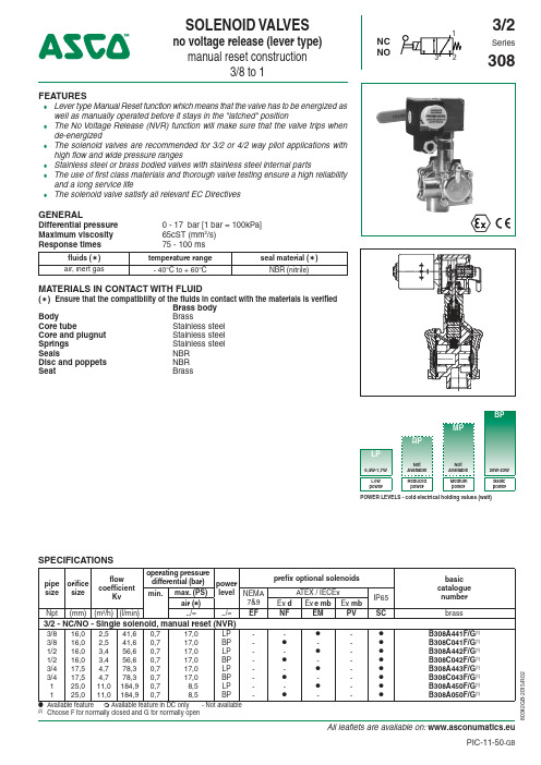
All leaflets are available on: www.asconumatics.euPIC-11-50-GB80342G B -2015/R 02FEATURES●Lever type Manual Reset function which means that the valve has to be energized as well as manually operated before it stays in the "latched" position● The No Voltage Release (NVR) function will make sure that the valve trips when de-energized● The solenoid valves are recommended for 3/2 or 4/2 way pilot applications with high flow and wide pressure ranges● Stainless steel or brass bodied valves with stainless steel internal parts● The use of first class materials and thorough valve testing ensure a high reliability and a long service life● The solenoid valve satisfy all relevant EC DirectivesGENERALDifferential pressure 0 - 17 bar [1 bar = 100kPa]Maximum viscosity 65cST (mm 2/s)Response times75 - 100 msfluids (✶)temperature range seal material (✶)air, inert gas- 40°C to + 60°CNBR (nitrile)MATERIALS IN CONTACT WITH FLUID(✶) Ensure that the compatibility of the fluids in contact with the materials is verified Brass body Body Brass Core tube Stainless steel Core and plugnut Stainless steel Springs Stainless steel Seals NBR Disc and poppets NBR Seat BrassSPECIFICATIONSpipe size orificesize flowcoefficientKvoperating pressure differential (bar)power level prefix optional solenoidsbasic catalogue number min.max. (PS)NEMA 7&9A TEX / IECEx IP65air (✶)Ex d Ex e mb Ex mb Npt (mm)(m 3/h)(l/min)~/=~/=EFNF EM PVSC brass 3/2 - NC/NO - Single solenoid, manual reset (NVR)3/83/81/21/23/43/41116,016,016,016,017,517,525,025,02,52,53,43,44,74,711,011,041,641,656,656,678,378,3184,9184,90,70,70,70,70,70,70,70,717,017,017,017,017,017,08,58,5LP BP LP BP LP BP LP BP---------●-●-●-●●-●-●-●---------●●●●●●●●B308A441F/G (1)B308C041F/G (1)B308A442F/G (1)B308C042F/G (1)B308A443F/G (1)B308C043F/G (1)B308A450F/G (1)B308A050F/G (1)● Available feature ❍ Available feature in DC only - Not available (2)Choose F for normally closed and G for normally openBPMPRPLP0,4W-1,7W Not Available Not Available 20W-23W LowpowerReduced powerMedium powerBasic powerPOWER LEVELS - cold electrical holding values (watt)SOLENOID VALVESno voltage release (lever type)manual reset construction3/8 to 13/2NC NOSeries308All leaflets are available on: www.asconumatics.eu 11-50-280342G B -2015/R 02PRODUCT SELECTION GUIDESTEP 1Select basic catalogue number, including pipe thread indentification letter. Refer to the specifications table on page 1 or 2.Example: B308C042FSTEP 2Select prefix (combination). Refer to the specifications table on page 1 and the prefix table on page 2, respect the indicated power level.Example: EMETSTEP 3Select suffix (combination) if required. Refer to the suffix table on page 2, respect the indicated power level.Example: VSTEP 4Select voltage. Refer to standard voltages on page 3.Example: 230V / 50HzSTEP 5Final catalogue / ordering number. Example:EMET B308C042F V 230V / 50 HzOPTIONS & ACCESSORIEScatalogue number spare parts kit no. (1)mouting bracket no.~=SC B 308C041SC B 308C042SC B 308C043SC B 308C050SC B 308A441SC B 308A442SC B 308A443SC B 308A450C318534C318534C314591C306759C314590-C314591C306759-C314548C314591C306759C314590-C314591C306759038713-000038713-000038713-000038713-000038713-000038713-000038713-000038713-000(1)Standard prefixes/suffixes are also applicable to kits PREFIX TABLEprefix description power level 1234567LP RP MP BP E M Waterproof IP66/67 - Metal enclosure (EN/IEC 60079-7,-18 and -31)*●---E T Threaded conduit/hole (M20 x 1,5)●--●N F Flameproof - Aluminium (EN/IEC 60079-1, 60079-31)*---●S C Solenoid with spade plug connector (EN/IEC 60730)●--●W P Waterproof IP67 - Metal enclosure ●--●W S Waterproof IP67 - 316 SS enclosure ●--●W S E M Waterproof IP66/67 - 316 SS enclosure (EN/IEC 60079-7,-18 and -31)*●---WS N F Flameproof - 316L SS (EN/IEC 60079-1, 60079-31)*---●T Threaded conduit (1/2" NPT)●--●H C Class H - Battery charging circuit ---●H T Class H - High temperature---●X Other special constructions●--●SUFFIX TABLEsuffix descriptionpower level 12345LP RP MP BP N V FPM (fluoroelastomer) and parts cleaned for oxygen service ●--●VFPM (fluoroelastomer)●--●C O Epoxy coating on all external surfaces ●--●M BMounting bracket●--●● Available feature❍ Available feature in DC only - Not available* A TEX/IECEx valves using these solenoids are approved according to EN 13463-1 (non electrical)ORDERING EXAMPLES VALVES:SC B 308A 006NV 24V / DC WS B 308A 406CO 24V / DC WPB 308A 006NV 24V / DCprefix voltage pipe thread suffixbasic numberORDERING EXAMPLES KITS:C318534 (2)WS C314591WS C306759prefixbasic number(2)Basic kit number applies to SC coil constructionAll leaflets are available on: www.asconumatics.eu11-50-38 0 3 4 2 G B -2 0 1 5 / R 0 2EXPLANATION OF TEMPERATURE RANGES OF SOLENOID VALVESValve temperature range The valve temperature range (TS) is determined by the selected seal material, the temperaturerange for proper operation of the valve and sometimes by the fluid (e.g. steam)Operator ambient temperature range The operator ambient temperature range is determined by the selected power level and thesafety codeTotal temperature range The temperature range of the complete solenoid valve is determined by the limitations of bothtemperature ranges aboveELECTRICAL CHARACTERISTICSCoil insulation class FConnector Spade plugConnector specification ISO 4400 (cable Ø 6-10 mm)Electrical safety IEC 335Standard voltages: DC (=) 24V - 48V; Allowable voltage variation +10%, -15%AC (~) 24V - 48V - 115V - 230V/50 Hz; Other voltages are available on requestprefix optionpower ratings operatorambienttemperaturerange (TS)safety codeelectricalenclosureprotection(EN 60529)replacement coil / kittype(2) inrush holding hot/cold~~=~=(VA)(VA)(W)(W)(C°)(1)230V/50 Hz24V/DCBasic power (BP)SC 240432016/23-40 to +75EN 60730IP65, moulded400-525-217400-625-24201/02 WP/WS240432016/23-40 to +75EN 60730IP67, steel/SS400-505-217400-605-24203/04 NF/WSNF240432016/23-60 to +60II2G Ex d IIC Gb T4, II2D Ex tb IIIC Db IP66/67, alu./SS400-505-217400-605-242-Low Power (LP)SC1,21,21,21,3/1,3-40 to +75EN 60730IP65, moulded400-929-097400-929-04205/06 WP/WS1,21,21,21,3/1,3-40 to +75EN 60730IP67, steel/SS400-930-097400-930-04207/08 EM/WSEM1,21,21,21,3/1,3-40 to +60II2G Ex e mb IIC Gb T6, II2D Ex tb IIIC Db IP66/67, steel/SS400-930-097400-930-04207/08(1) Temperature range can be limited by sealings(3 )Multiple coil kits are available under ATEX/IECEx, contact us(2) Refer to the dimensional drawings on page 4- Not availableADDITIONAL OPTIONS●Other pipe threads are available on request●Compliance with “UL”, “CSA” and other local approvals available on request●1/2” NPT (prefix “T”) and M20 x 1,5 (prefix “ET”) conduits (aluminium or 316 SS) available for steel solenoid housing●Special moulded-in solid state components for peak voltage suppression and/or rectification (four diode bridge) INSTALLATION●The solenoid valves have to be mounted vertically and in an upright position for best performance●Multi language installation/maintenance instructions are included with each valve●Threaded pipe connection identifier is B = NPT (ANSI 1.20.3)●Other pipe threads are available on request●Normally closed (F) and normally open contruction (G) have internal pilot connections and need 0,7 bar min. operatingpr e ssur e●Ex e mb (prefix “EM”) execution: solenoid enclosure has a cable gland with integral strain relief for cables with an o.d.from 7 to 12 mm and is provided with an internal and external connection facility for an earthing or bonding conductorAll leaflets are available on:www.asconumatics.eu 11-50-480342G B -2015/R 02DIMENSIONS (mm), WEIGHT (kg)TYPE 01:TYPE 02:Epoxy mouldedSC: IEC 335 / ISO 4400Epoxy mouldedSC: IEC 335 / ISO 4400308C041F / C041G / C042F / C042G308C043F / C043G / A050F / A050GAB DCG FJ HEAEJ GHFDC B KL TYPE 03:TYPE 04:Metal, epoxy coated / AISI 316 SS WP / WS: IEC 335Metal, epoxy coated / AISI 316 SS WP / WS: IEC 335308C041F / C041G / C042F / C042G308C043F / C043G / A050F / A050GAEJ G H FDCB AEJ GHFDCBK LTYPE 05:TYPE 06:Epoxy mouldedSC: IEC 335 / ISO 4400Epoxy mouldedSC: IEC 335 / ISO 4400308A441F / A441G / A442F / A442G308A443F / A443G / A450F / A450GAB CDFG HJ EABCDFGHJ KLEAll leaflets are available on: www.asconumatics.eu11-50-580342G B -2015/R 02MOUNTING BRACKETSBracket number : 038713-000Material : Zinc plated steelØ7,142type prefix option power level A B C D E F G H J K L weight 01SC BP 1281310915712770140169194--3,20 kg 02SCBP 12849 84 14312731861331491922183,20 kg 03WP , WS BP 1341310915713070153182194--3,20 kg 04WP , WS BP 13449 8414313031861371632062183,40 kg 05SC LP 1281310915715370140169194--3,40 kg 06SCLP 12849 8414315331861591491922183,40 kg 07WP , WS, EM, WSEM LP 1341310915716670153182194--3,40 kg 08WP , WS, EM, WSEMLP134498414316631861731632062183,40 kgDIMENSIONS (mm), WEIGHT (kg)TYPE 07:TYPE 08:Metal, epoxy coated / AISI 316 SS WP / WS: IEC 335EM / WSEM: EN/IEC 60079-7+18+31Metal, epoxy coated / AISI 316 SS WP / WS: IEC 335EM / WSEM: EN/IEC 60079-7+18+31308A441F / A441G / A442F / A442G308A443F / A443G / A450F / A450GAB CDFG H JEABCDFGHJ K LEAll leaflets are available on: www.asconumatics.eu 11-50-6PIC-11-5-GB--Availability,designandspecificationsaresubjecttochangewithoutnotice.Allrightsreserved.8342GB-215/R2。
rainssion 阀门电动执行器 使用说明书
Rainssion 阀门电动执行器使用说明书一、产品简介Rainssion 阀门电动执行器是一种用于控制阀门开关的自动化设备。
它具有结构紧凑、操作简便、可靠性高等特点,广泛应用于工业自动化领域。
本说明书将为您介绍Rainssion 阀门电动执行器的安装、操作、维护及常见问题解决方案等内容。
二、设备安装1.确认电源电压与设备额定电压相符,并确保电源具有过载保护功能。
2.根据阀门类型和尺寸,选择合适的执行器型号。
3.按照安装指南将执行器安装在阀体上,确保安装牢固、稳定。
4.连接电源线及控制信号线,确保连接正确、牢固。
5.打开电源开关,检查执行器是否正常工作。
三、操作步骤1.接通电源,打开电源开关。
2.根据控制信号(如4-20mA或0-10V)调整执行器输出,控制阀门开度。
3.通过控制信号逐步调整阀门位置,直至达到所需工作状态。
4.定期检查阀门工作状态,确保其正常工作。
5.当需要关闭阀门时,只需将控制信号调整至关闭位置即可。
四、维护与保养1.定期检查执行器及附件,确保其完好无损。
2.定期清洗阀体及执行器表面,保持清洁。
3.检查电源线及控制信号线是否松动或破损,如有异常及时更换。
4.如发现执行器工作异常或有损坏,应及时维修或更换。
5.定期对执行器进行润滑,延长其使用寿命。
五、常见问题与解决1.电源故障:检查电源是否正常,电源线是否松动或破损。
如有问题,及时更换电源线或维修电源。
2.控制信号异常:检查控制信号是否正常,信号线是否松动或破损。
如有问题,及时更换信号线或维修控制信号源。
3.阀门不动作:检查执行器及阀体是否正常,调整控制信号检查阀门是否被堵塞或卡住。
如有问题,及时清洗或维修阀体和执行器。
4.异常响声:检查执行器内部是否有异物或损坏部件。
如有问题,及时清理异物或更换损坏部件。
5.温度过高:检查执行器散热是否良好,如环境温度过高或设备过载工作,需加强散热措施或减轻负载。
六、安全注意事项1.在安装、操作及维护过程中,应始终遵守安全操作规程,确保人员安全。
- 1、下载文档前请自行甄别文档内容的完整性,平台不提供额外的编辑、内容补充、找答案等附加服务。
- 2、"仅部分预览"的文档,不可在线预览部分如存在完整性等问题,可反馈申请退款(可完整预览的文档不适用该条件!)。
- 3、如文档侵犯您的权益,请联系客服反馈,我们会尽快为您处理(人工客服工作时间:9:00-18:30)。
Non-Invasive Electric Actuator Electronic control module debugginginstructionsVersion V201SummaryThis component can receive the DCS system on-off signals (passive dry contact of active, active 24 v, 220 v, keep running can switch) or analog signals (DC4-20 ma, 0 to 10 v, etc.), direct drive electric actuators switch action or adjust the action. Output DC4-20 ma feedback current and contact/remote control state instructions. The component integration the servo control unit, solid-state drive unit, liquid crystal display unit, knobs and other ancillary units and aluminum shell assembly operation.The product operates as a fool camera is simple, like intelligent perfect protection function.2Operating Instructions2.1Knob Operating InstructionsThe red knob is the mode button, can be switched between Local/Stop/Remote. Or in a set state, to save the menu contents (from the stop bit screwed to the site) or to exit the menu(from the stop bit screwed into the remote).Black knob for the operating button can be opened or closed operation at the local.Or to plus or minus in the set state.With button operation, short time effect for the inching mode. When the operation button is effective for more than 3 seconds, in the lower right corner of the LCD, the bc is displayed automatically entered into the hold mode. When actuator movement, click the action button reverse rotation or spin mode button to Stop, the actuator Array stops.2.2 setting tool description (setting tool are optional, needto please when ordering special instructions)"Up" button = Open calibration key, "Down" button = close calibrationkey, "Enter" button = Confirm key or Save key"Stop" button = stop key, "Open" button = open key, "Close" button =close key.When mode button at Local location, press "Open" button to performopen, press "Close" button to perform off. In the action, press the"Stop" button to stop the move, short press "Close" to stop the openingprocess, short press "Open" to stop the closing process.In local mode, even by three "Up" key to enter the open position calibration status, "Open", "Close" and "Stop" keys to control the electric actuator to open, close and stop, "Enter" key to save the trip, "Stop "key is used to return.In local mode, even by three "Down" key to enter the closed position calibration status, like the rest of the operation as above.3Signal query (LCD lower left corner for a signal check area) 3.1 Remote control signal inquiryWhen the mode button is screwed into the Remote, the remote control signal received is displayed in the lower-left corner of the LCD. Switch type: show OP represents a open signal, show CL represents a close signal, show BC represents a keep signal (multi state of coexistence of alternate display). Regulating type: to display the received control current value or voltage value.3.2 Valve position signal queryWhen the mode button is screwed onto the Local, the LCD shows the valve position signal in lower left corner. When using a potentiometer, show the percentage of resistance (d01 ~ d99); When using 12 encoder, shows the percentage of the encoder (b01 ~ b99); When using 18 encoder, display micrometer ratio of the encoder (001 to 999).4 4 Stroke calibrations4.1 Calibration for close limit:The mode button at the Stop position, the rotary operation knob to the Close position for about 3 seconds, until the letter L is flashing of the LCD to release operation button, then the mode button to the Local position, now letter L no longer flashes and the system into the closed position calibration status. The actuator can open or close by the operating button. When the actuator operates to the closed position, then the mode button to spin the Stop position, and back to the Local position, at this time the red LED flashing two times said the closed position calibration is completed. If the mode button is screwed to the Remote position from Stop position, that exit travel calibration.4.2 Calibration for open limitThe mode button at the Stop position, the rotary operation knob to the Open position for about 3 seconds, until the letter H is flashing of the LCD to release operation button, then the mode button to the Local position, now letter H no longer flashes and the system into the open position calibration status. The actuator can open or close by the operatingmode button to spin the Stop position, and back to the Local position, at this time the green LED flashing two times said the open limit position calibration is completed. If the mode button is screwed to the Remote position from Stop position, that exit travel calibration.Note: When you save a stroke, display Fu or Fn characters on the LCD, please re-adjust potentiometer or rotary encoder range, and recalibrate the trip.5Feedback current trimming5.1 Feedback current 4mA trimmingThe mode button at the Stop position, the rotary operation knob to the Open position for about 10 seconds, until the letter LF is flashing of the LCD to release operation button, then the mode button to the Local position and back to the Stop position, and the system into the 4mA current trimming status. At this point,the size of the output current can be adjusted by the operating button. When adjusting the output current reaches 4mA, then mode button to spin the Local position, this time the red LED flashes three times, said 4mA output current trim is complete. If the mode button to Stop position from Remote position, which exit status of the output current trim.5.2 Feedback current 20mA trimmingThe mode button at the Stop position, the rotary operation knob to the Open position for about 10 seconds, until the letter HF is flashing of the LCD to release operation button, then the mode button to the Local position and back to the Stop position, and the system into the 20mA current trimming status. At this point,the size of the output current can be adjusted by the operating button. When adjusting the output current reaches 4mA, then mode button to spin the Local position, this time the green LED flashes three times, said 20mA output current trim is complete. If the mode button to Stop position from Remote position, which exit status of the output current trim.6About dead zoneThe dead zone to adapt automatically, without setting can ensure that in any conditions without oscillation, and the positioning precision is higher.7Alarm description (error code displayed on the LCD in the lower right corner) FaultcodeFault informationFA Actuator running direction errorFu V alve position potentiometer or encoder Angle is too largeFn V alve position potentiometer or encoder Angle is too smallFP Power phaseFF Broken valve position potentiometer, rotary to blind or pick the wrong line, or encoder failure.FC Over closed torqueFO Over open torqueFH Remote control signals to open and close signals exist (only on-off type)FS Control current signal is lost (only positioning)Fb Current control signal calibration error(only positioning)Fd Stall or other causes the valve position does not changeFL Limit contact line or torque contact line reversedFE The motor is too hot or the torque public terminal is openNOTE: The green LED is the open limit position light on the screen, the red LED is closed position light on the screen.8Advanced SettingsNOTE: All the Advanced Settings can be set after the mode button in the "Local" position. Advanced settings must open the electrical box cover and you can operate. The Close Key and Open Key mentioned below are in the electronic control board.8.1 Action when the control current loss:(Only positioning type, default: Remain in Situ)8.1.1 To press the “Close Key” and power up for 3 seconds until the red LED on the board is lit. And you release the key, then the red LED flashes three times; the “FullClose” setup is completed.8.1.2 To press the “Open Key” and power up for 3 seconds until the green LED on the board is lit. And you release the key, then the green LED flashes three times; the “Full Open” setup is completed.8.1.3 Simultaneously press two keys and power up for 3 seconds until the green and red LEDs on the board are lit. And you release the two keys simultaneously, then the two LEDs flashes three times; the “Remain in Situ” setup is completed.8.2 Control current calibration:(Only positioning type)8.2.1 To send 4mA control current to the module from the outside, press the “Close Key” and power up for 10 seconds until the red LED on the board is lighted second times. And you release the key, then the red LED flashes three times; and the4mA calibration is completed.8.2.2 To send 20mA control current to the module from the outside, press the “Open Key” and power up for 10 seconds until the green LED on the board is lighted second times. And you release the key, then the green LED flashes three times; and the20mA calibration is completed.8.3 Polarity for the control current:(Only positioning type)20mA = Full Open /4mA = Full Open (default:20mA = Full Open) Simultaneously press “Open Key” and “Close Key” and then power up for 10 seconds. To release the key after the red LED and green LED second lights up. Short press “Open Key” or “Close Key” to alternately lit red LED or green LED. The red LED light represents “20mA = Full Open”, the green LED light represents “4mA = Full Open”. Simultaneously press “Open Key” and “Close Key” for 3 seconds. To release two keys after the two LEDs lights up. Then corresponding LED flashes three times, the polarity for the control current setup is complete.8.4 Two-Wire Control:(Only on-off type)Disable or Open First or Close First (default: Disable)8.4.1Close FirstYou press “Close Key” and then power up for 10 seconds. The key is released after the red LED second light up. And the red LED flashes three times, this setup is complete. This Close First refers to the actuator close operation when voltages signal on the “Remote Close” terminal of the actuator. But no voltage signal, actuators open operation. When wiring, “Remote Open” terminal connected to 24V +.8.4.2Open FirstYou press the “Open Key” and then power up for 10 seconds. The key is released after the green LED second light up. And the green LED flashes three times, this setup is complete.This Open First refers to the actuator open operation when voltages signal on the “Remote Open” terminal of the actuator. But no voltage signal, actuators close operation. When wiring, “Remote Close” terminal connected to 24V +.8.4.3 DisableYou press the two keys simultaneously and then power up for 10 seconds. The key is released after the two LEDs second lights up. Then the two LEDs flashes three times, this setup is complete.8.5 Close direction:Clockwise /Anti-clockwise (default:Clockwise)You press the “Open Key” and “Close Key” simultaneously and then power up for 20 seconds. The keys are released after the red LED and green LED third lights up. Short press “Open Key” or “Close Key” to alternately lit red LED or green LED. Red LED light represents “Clockwise”, green LED light represents “Anti-clockwise”. You press the two keys simultaneously for 3 seconds. The keys is released after the two LEDs light up. Then corresponding LED flashes three times, the Close direction setup is complete.9Common problems to deal withPower LED is not lit or digital display does not show 1. Power is not actually access. 2. voltage is too low 3. Wiring fault. 4. Module badLEDs and digital display abnormal 1. See fault code.2. Query information.3. Replace the moduleAfter power on ,actuator can be not control in the LOCAL and REMOTE mode 1. Wiring fault or loose wiring. 2. Fault Protection.3. Motor bad or stuck.4. Bad start capacitor.5. module badLOCAL mode work is normal but the REMOTE mode can't control 1. No signal or junction anti- , 2. Bad or no knob plate in Remote3. Positive / reaction set wrong.4. Module badREMOTE mode work is normal but the LOCAL mode can't control 1. Not in LOCAL mode. 2. Knobs board bad or not at the scene mode. 3. Operation button is not properly screwed in placeActuator can open but not close or can close but not open 1. Torque wiring fault or loose wiring. 2. to limit position or over torque3. Motor bad or stall or wiring fault.4. Module badThe action immediately after power on 1. Wiring fault. 2. control signal is present3. Implementation the action when the control current loss4. Set the wrong.5. module badThe middle position can move but to the limit position does not move 1. Reverse limit switch line. 2. Motor bad or loose wiring 3. Module badThe direction of movement is the anti 1. Motor lines reversed. 2. Anti valve calibration.3. Signal Reverse4. Polarity for the control current or closing direction set wrong.No output current or sometimes no 1. The output wiring fault or bad. 2. Module bad 3. potentiometer wiring fault or loose wiringFeedback current is larger or smaller or unchanged 1.Potentiometer failure. 2. Calibration error.3. module bad4. potentiometer meshing with drive gear not wellNote: Please strictly in accordance with the wiring diagram electrical wiring connection.Like has the change, without notice。