CSreport_lab1_DianYu&QiangHuang
CS系列电化学工作站
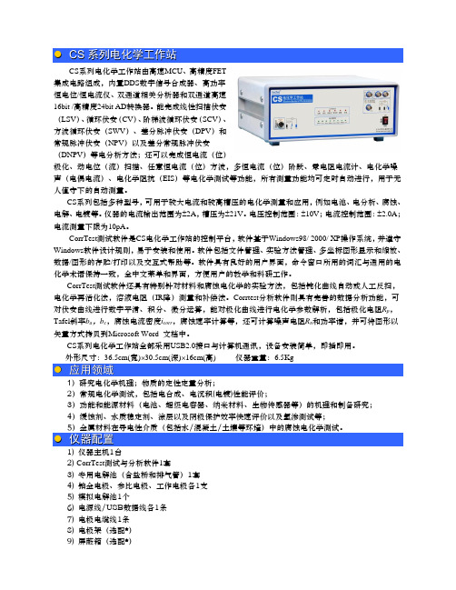
●C S系列电化学工作站CS系列电化学工作站由高速MCU、高精度FET集成电路组成,内置DDS数字信号合成器、高功率恒电位/恒电流仪、双通道相关分析器和双通道高速16bit /高精度24bit AD转换器。
能完成线性扫描伏安(LSV)、循环伏安(CV)、阶梯波循环伏安(SCV)、方波循环伏安(SWV)、差分脉冲伏安(DPV)和常规脉冲伏安(NPV)以及差分常规脉冲伏安(DNPV)等电分析方法;还可以完成恒电流(位)极化、动电位(流)扫描、任意恒电流(位)方波,多恒电流(位)阶跃、零电阻电流计、电化学噪声(电偶电流)、电化学阻抗(EIS)等电化学测试等功能,所有测量功能均可定时自动进行,用于无人值守下的自动测量。
CS系列包括多种型号,可用于较大电流和较高槽压的电化学测量和应用,例如电池、电分析、腐蚀、电解、电镀等。
仪器的电流输出范围为±2A,槽压为±21V。
电压控制范围:±10V;电流控制范围:±2.0A;电流测量下限为10pA。
CorrTest测试软件是CS电化学工作站的控制平台,软件基于Windows98/ 2000/ XP操作系统,并遵守Windows软件设计规则,易于安装和使用。
软件包括文件管理、实验方法管理、多坐标图形显示和缩放、数据/图形的存贮/打印以及交互式帮助等。
软件具有良好的用户界面,命令窗口所用的词汇与通用的电化学术语保持一致,全中文菜单和界面,方便用户的教学和科研工作。
CorrTest测试软件还具有特别针对材料和腐蚀电化学的实验方法,包括钝化曲线自动或人工反扫,电化学再活化法,溶液电阻(IR降)测量和补偿法。
Corrtest分析软件则具有完善的数据分析功能,可对伏安曲线进行数字平滑、积分、微分运算,能对极化曲线进行电化学参数解析,包括极化电阻R p,Tafel斜率b a,b c,腐蚀电流密度i corr,腐蚀速率计算等,还可计算噪声电阻R n和功率谱,并可将图形以矢量方式拷贝到Microsoft Word 文档中。
总线防盗报警控制器-大华

使用,但是却会导致系统自动的转发相应端口的数据,从而导致本应该受限的数据被他人窃 取。 如果已在路由器上手工打开了 HTTP 和 TCP 端口映射,我们强烈建议您关闭此功能。在实际 的使用场景中,我们强烈建议您不开启此功能。
电源要求
请务必按照要求使用电池,否则可能导致电池起火、爆炸或燃烧的危险! 更换电池时只能使用同样类型的电池! 产品必须使用本地区推荐使用的电线组件(电源线),并在其额定规格内使用。 请使用满足 SELV(安全超低电压)要求的电源,并按照 IEC60950-1 符合 Limited Power
部分老版本的 IP 摄像机固件,系统的主密码更改后,ONVIF 密码不会自动跟着更改。你需要更 新摄像机的固件或者手动更新 ONVIF 密码。 6. 只转发必须使用的端口 只转发必须使用的网络端口。避免转发一段很长的端口区。不要把设备的 IP 地址设置成 DMZ。 如果摄像机是连接到本地的 NVR,你不需要为每一台摄像机转发端口,只有 NVR 的端口需
在适用法律未明令禁止的程度下,对于因使用或无法使用本产品或服务而引起的任何利润、 收入、销售损失、数据丢失或采购替代商品或服务的成本、财产损害、人身伤害、业务中断、 商业信息损失,或者任何特殊的、直接的、间接的、附带的、经济性、覆盖性、惩罚性、特 殊或从属损害,无论是基于何种责任理论(合同、侵权、过失或其他),本公司及其员工、 许可方或附属公司都不承担赔偿责任,即使其已被告知存在此种损害的可能性也是如此。某 些司法管辖区不允许对人身伤害、附带或从属损害等进行责任限制,则此限制可能不适用于 您。
要被转发。 7. 关闭 SmartPSS 的自动登录功能 如果你使用 SmartPSS 来监控你的系统而你的电脑是有多个用户,请必须把自动登录功能关闭。 增加一道防线来防止未经授权的人访问系统。 8. 在 SmartPSS 上使用不同于其他设备的用户名和密码 万一你的社交媒体账户,银行,电邮等账户信息被泄漏,获得这些账户信息的人也无法入侵你的 视频监控系统。 9. 限制普通账户的权限 如果你的系统是为多个用户服务的,请确保每一个用户只获得它的作业中必须的权限。
施耐德电气低压配电产品选型指南说明书
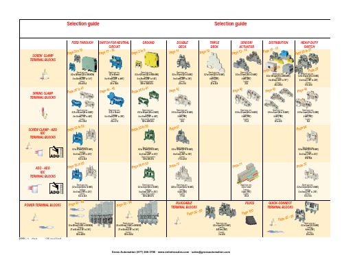
ABB EntrelecSommaireBU0402061SNC 160 003 C0205SummarySelection guide ....................................................................................page 1Screw clamp ........................................................................................page 2Feed through and ground terminal blocks .......................................................page 2 - 5 to 10Single pole, multiclamp terminal blocks..........................................................................page 4Feed through terminal blocks - Double-deck................................................................page 11Feed through terminal blocks - Triple-deck...................................................................page 12Three level sensor, terminal blocks without ground connection...................................page 13Three level sensor, terminal blocks with ground connection ........................................page 14Terminal blocks for distribution boxes, double deck + protection .......................page 15 - 16Interruptible terminal blocks for neutral circuit......................................................page 17 - 18Distribution : phase, ground terminal blocks .......................................................page 19 to 21Single pole or four pole distribution blocks..........................................................page 22 to 24Heavy duty switch terminal blocks with blade......................................................page 25 - 26Heavy duty switch terminal blocks with push-turn knob..............................................page 26Heavy duty switch terminal blocks with contact control pull lever...............................page 29Heavy duty switch terminal blocks with blade - Double-deck .....................................page 27Fuse holder terminal blocks for 5x20 mm (.197x.787 in.) and 5x25 mm (.197x.984 in.)or 6.35x25.4 mm (1/4x1 in.) and 6.35x32 mm (1/4x11/4 in.) fuse s.........................................page 28 - 29Fuse holder terminal blocks for 5x20 mm (.197x.787 in.) and 5x25 mm (.197x.984 in.) fuses -Double-dec k.....................................................................................................................page 27Terminal blocks for test circuits with sliding bridge ......................................................page 30Terminal blocks for metering circuits.............................................................................page 31ESSAILEC terminal blocks.............................................................................................page 32Safety connection terminal blocks ................................................................................page 33Miniblocks for EN 50045 (DIN 46277/2) rail ..........................................................page 34 - 35Spring clamp ......................................................................................page 36Angled terminal blocks - Feed through and ground .....................................................page 36Feed through and ground terminal blocks ...........................................................page 37 to 41Feed through terminal blocks - Double deck ................................................................page 42Terminal blocks for sensors / actuators ........................................................................page 42Terminal blocks for distribution boxes...........................................................................page 43Switch terminal blocks for neutral conductor........................................................page 44 - 45Heavy duty switch terminal blocks with blade..............................................................page 46Fuse holder terminal blocks for 5x20 mm (.197x.787 in.) and 5x25 mm (.197x.984 in.) fuse s....page 47Miniblocks Spring clamp ......................................................................................page 48 to 52ADO - Screw clamp ...........................................................................page 53Feed through and ground terminal blocks ...........................................................page 53 to 56Feed through and ground terminal blocks - Double-deck............................................page 57Heavy duty switch terminal blocks with blade..............................................................page 58Fuse holder terminal blocks for 5x20 mm (.197x.787 in.) and 5x25 mm (.197x.984 in.) fuse s ......page 59 - 60Miniblocks ADO - Screw clamp............................................................................page 61 to 65ADO - ADO .........................................................................................page 66Feed through and ground terminal blocks ...........................................................page 66 to 69Feed through and ground terminal blocks - Double-deck............................................page 70Terminal blocks for sensors / actuators ........................................................................page 71Heavy duty switch terminal blocks with blade..............................................................page 72Fuse holder terminal blocks for 5x20 mm (.197x.787 in.) and 5x25 mm (.197x.984 in.) fuse s ......page 73 - 74Miniblocks ADO - ADO .........................................................................................page 75 to 79Accessories ADO ...........................................................................................................page 80Power terminal blocks .............................................................page 81 to 84Quick-connect terminal blocks .................................................page 85 - 86Terminal blocks for railway applications ................................page 87 to 97Pluggable terminal blocks .....................................................page 98 to 100Accessories......................................................................................page 101Marking..................................................................................page 102 to 104GrossAutomation(877)268-3700··*************************PR30PR3.Z2PR3.G2PR5PR4PR1.Z2Rated wire size :Rated wire size :Rated wire size :Rated wire size :Mounting railsShield terminals forcollector barMarking tableHorizontal Rated wire size :0.5 to 16 mm² (22 to 8 AWG)Rated wire size :Rated wire size :Rated wire size :P a g e t o 29e30 t o 32ag e e3P a ge 8 t o 60a g e6t o 6574P a ge 7 t o 79P a ge 9P a g P a gGrossAutomation(877)268-3700··*************************2ABB Entrelecd010830402051SNC 160 003 C0205MA 2,5/5 - 2.5 mm² blocks - 5 mm .200" spacingAccessoriesGrossAutomation(877)268-3700··*************************3ABB Entrelec D010740402051SNC 160 003 C0205M 4/6 - 4 mm² blocks - 6 mm .238" spacingAccessoriesGrossAutomation(877)268-3700··*************************4ABB EntrelecD011030402051SNC 160 003 C0205M 4/6.3A - 4 mm² blocks - 6 mm .238" spacingM 4/6.4A - 4 mm² blocks - 6 mm .238" spacingGrossAutomation(877)268-3700··*************************5ABB Entrelec D010840402051SNC 160 003 C0205M 6/8 - 6 mm² blocks - 8 mm .315" spacingAccessoriesGrossAutomation(877)268-3700··*************************6ABB EntrelecD010850402051SNC 160 003 C0205M 10/10 - 10 mm² blocks - 10 mm .394" spacingAccessoriesGrossAutomation(877)268-3700··*************************7ABB Entrelec D010860402051SNC 160 003 C0205M 16/12 - 16 mm² blocks - 12 mm .473" spacingAccessoriesGrossAutomation(877)268-3700··*************************8ABB EntrelecD010870402051SNC 160 003 C0205M 35/16 - 35 mm² blocks - 16 mm .630" spacingGrossAutomation(877)268-3700··*************************M 95/26 - 95 mm² blocks - 26 mm 1.02" spacingM 70/22.P - 70 mm² ground block with rail contact - 22 mm .630" spacingSelection35 mm / 1.37"12 mm / 0.47"14-30 Nm / 124-260 Ib.in 1.2-1.4 Nm / 10.6-12.3 Ib.in1000600600415400400577070240 mm 2500 MCM 500 MCM 10 mm 2 6 AWG 6 AWG IEC UL CSANFC DIN0.5 - 160.5 - 100 AWG-600 MCM 2 AWG-500 MCM 50 - 30035 - 24018-6 AWGD 150/31.D10 - 150 mm² blocks - 31 mm 1.22" spacingCharacteristicsD 240/36.D10 - 240 mm² blocks - 36 mm 1.41" spacingSelectionWire size main circuit mm² / AWG VoltageV Current main circuit A Current outputARated wire size main circuit mm² / AWG Rated wire size outputmm² / AWG Wire stripping length main circuit mm / inches Wire stripping length output mm / inches Recommended torque main circuit Nm / Ib.in Recommended torque outputNm / Ib.inSolid Stranded Solid Stranded Wire size output mm² / AWG9.5 mm / .37"0.5-0.8 Nm / 4.4-7.1 Ib.in5003003003220204 mm 212 AWG12 AWG0.2 - 422-12 AWG 22-12 AWG 0.22 - 4IEC ULCSANFC DINCharacteristicsWire size mm² / AWGSolid Stranded D 4/6.T3 - 4 mm² blocks - 6 mm .238" spacingSelectionVoltage V CurrentARated wire sizemm² / AWG Wire stripping length mm / inches Recommended torqueNm / Ib.inM 4/6.T3.P - 4 mm² block - 6 mm .238" spacingD 2,5/6.D - 2.5 mm² blocks - 6 mm .238" spacingD 2,5/6.DL - 2.5 mm² blocks - 6 mm .238" spacingD 2,5/6.DPA1 - 2.5 mm² blocks - 6 mm .238" spacingD 2,5/6.DPAL1 - 2.5 mm² blocks - 6 mm .238" spacingD 4/6... - 4 mm² blocks - 6 mm .238" spacingD 4/6.LNTP - 4 mm² closed blocks - 17.8 mm .700" spacingMA 2,5/5.NT- 2.5 mm² block - 5 mm .200" spacingAccessories**SFB2 : 16 to 35 mm² 6 to 2 AWG H= 3 mm/.12"M 10/10.NT- 10 mm² block - 10 mm .394" spacingAccessories(1) Except for M 35/16 NT (closed block)*SFB1 : 0.5 to 35 mm² 18 to 2 AWG H= 7 mm/.28"**SFB2 : 16 to 35 mm² 6 to 2 AWG H= 3 mm/.12"MB 4/6... - 4 mm² blocks - 6 mm .238" spacingMB 6/8... - 6 mm² blocks - 8 mm .315" spacingMB 10/10... - 10 mm² blocks - 10 mm .394" spacingBRU 125 A - 35 mm² block - 27 mm 1.063" spacingBRU 160 A - 70 mm² block - 35.2 mm 1.388" spacingBRU 250 A - 120 mm² blocks - 44.5 mm 1.752" spacingBRU 400 A - 185 mm² block - 44.5 mm 1.752" spacingAccessoriesAccessoriesBRT 80 A - 16 mm² block - 48 mm 1.89" spacingBRT 125 A - 35 mm² block - 48 mm 1.89" spacingBRT 160 A - 50 mm² block - 50 mm 1.97" spacing9.5 mm / .37"0.5-0.6 Nm / 4.4-5.3 Ib.in4003003002010104 mm 210 AWG 12 AWG 0.5 - 422-10 AWG20-12 AWG0.5 - 2.5IEC ULCSANFC DINMA 2,5/5.SNB - 2.5 mm² blocks - 5 mm .200" spacingCharacteristicsM 4/6.SNB - 4 mm² blocks - 6 mm .238" spacingSelectionWire size mm² / AWGVoltage V CurrentARated wire sizemm² / AWG Wire stripping length mm / inches Recommended torqueNm / Ib.inSolid StrandedM 6/8.SNB - 6 mm² blocks - 8 mm .315" spacing - blade switchingSelectionAccessoriesM 4/8.D2.SF - for fuses 5x20 mm .197x.787 in. and 5x25 mm .197x.984 in. -4 mm² blocks - 8 mm .315" spacingM 4/6.D2.SNBT - 4 mm² blocks - 6 mm .238" spacing - blade switchM 4/8.SF- 4 mm² blocks - 8 mm .315" spacingM 4/8.SFL - 4 mm² blocks - 8 mm .315" spacing12 mm / .472"1.2-1.4 Nm / 10.6-12.3 Ib.in800(1)60060016252510 mm 210 AWG8 AWG0.5 - 1622-10 AWG 22-8 AWG 0.5 - 10IEC ULCSANFC DINCBD2SML 10/13.SF - for fuses 6.35x25.4 mm 1/4x1 in. and 6.35x32 mm 1/4x11/4 in. -10 mm² blocks - 13 mm .512" spacingSelectionAccessoriesCharacteristicsWire size mm² / AWGVoltage V CurrentARated wire sizemm² / AWG Wire stripping length mm / inches Recommended torqueNm / Ib.inSolid Stranded (1) Insulation voltage of terminal block - operating voltage : according to fuse.M 4/6.D2.2S2... - 4 mm² blocks - 6 mm .238" spacing11 mm / .43"0.8-1 Nm / 7.1-8.9 Ib.in50060030306 mm 28 AWG0.5 - 1022-8 AWG0.5 - 6IECULCSANFC DINM 6/8.ST... - 6 mm² blocks - 8 mm .315" spacingCharacteristicsWire size mm² / AWGVoltage V CurrentARated wire sizemm² / AWG Wire stripping length mm / inches Recommended torqueNm / Ib.inSolid Stranded M 6/8.STA - 6 mm² blocks - 8 mm .315" spacing(3)Only for M 6/8.STAM 4/6.ST- 4 mm² blocks - 6 mm .236" spacingBNT...PC...(2) Only for M10/10.ST-SnThe PREM IUM solution for testing the secondary circuits of current or voltage transformers.ESSAILEC, approved by the major electricity utilities, remains the premium choice for the energy market.Implemented in the transformers secondary circuits, ESSAILEC thanks to its intelligent “make before break” design eases and secures any intervention. Cutting the energy supply is avoided with zero risk for the operator.The plug and socket connection cuts cost installation as well as in-situ wiring errors. ESSAILEC is ideal for the wiring of sub-assemblies in the secondary circuits.ESSAILEC terminal blocksProtection relays,Protection relays,Testing :The ESSAILEC socket supplies energy to the protection or counting devices. The insertion of the test plug, which is connected to the measurement equipment, allows the testing of the devices, without perturbing the circuit.ESSAILEC blocks are well adapted to current or voltage measurement :-Current sockets with make before break contacts and pre-wired test plug for current measures-Voltage sockets with open contacts and pre-wired test plug for voltage measures-Up to 4 ammeters or 4 voltmeters connected to the test plugDistributing :The ESSAILEC plug is continuously mounted on the socket to supply current or voltage to secondary circuits sub assemblies.ESSAILEC blocks extreme versatility allow :-Safe current distribution with current socket with mobile contacts since the secondary circuit is not cut when plug is removed-Voltage or polarity distribution with dedicated voltage or polarity socket with closed contactESSAILEC is designed to offer :Great flexibility :-Connection multi contacts « plug and play »-Panel, rail, rack fixed mounting or stand-alone connector -Two wiring technologies, up to 10 mm²Extreme reliability :-Non symmetric blocks -Coding accessories -IP20 design -Locking system -Sealed coverR S T NFor technical characteristics and complete part numbers list, please ask for the ESSAILEC catalog10005006003225254 mm 21.65 mm²12 AWG 13 mm / .51"IECB.SCSANFC DINTS 50-180.5 - 0.8 Nm /4.4 - 7.1 Ib.in0.2 - 422-12 AWG0.22 - 40.5 - 1.50.28 - 1.6580050060041252562.512 AWG 13 mm / .51"0.8 - 1 Nm / 7.1 - 8.9 Ib.inIECB.S CSANFC DINTS 50-180.5 - 1020-12 AWG0.5 - 60.28 - 2.590050060046406510 mm 26 mm² 6 AWG 14 mm / .55"IECB.S UL/CSANFC DINTS 50-181.2 - 1.4 Nm / 10.6 - 12.3 Ib.in0.5 - 1620 - 6 AWG0.5 - 100.28 - 6M 4/6.RS - 4 mm² blocks - 6 mm .238" spacingCharacteristicsWire size mm² / AWGVoltage V CurrentARated wire sizemm² / AWG Wire stripping lengthmm / inches Recommended torque (screw)Nm / Ib.inSolid wire Stranded wire Solid wire Stranded wire Screw clampLugsM 6/8.RS - 6 mm² blocks - 8 mm .315" spacingCharacteristicsWire size mm² / AWGVoltage V CurrentARated wire sizemm² / AWG Wire stripping lengthmm / inches Recommended torque (screw)Nm / Ib.inSolid wire Stranded wire Solid wire Stranded wire Screw clampLugspending M 10/10.RS - 10 mm² blocks - 10 mm .394" spacingCharacteristicsWire size mm² / AWGVoltage V CurrentARated wire sizemm² / AWG Wire stripping lengthmm / inches Recommended torque (screw)Nm / Ib.inSolid wire Stranded wire Solid wire Stranded wire Screw clampLugspending SelectionAccessories(1) Only for block M 4/6.RS (4) For blocks M 4/6.RS and M 6/8.RS(2) Only for block M 6/8.RS(3) Only for block M 10/10.RSDR 1,5/4 - 1.5 mm² blocks - 4 mm .157" spacingDR 1,5/5... - 1.5 mm² blocks - 5 mm .200" spacing。
水上机器鱼5V5技术文档
水上机器鱼5V5技术文档一、仿真环境仿真环境是仿真使命运行所处的虚拟环境,其中包括仿真场地(模拟比赛或实验用水池的对象)、零个或多个仿真水球(模拟比赛或实验用水球的对象)、零个或多个仿真方形障碍物(模拟比赛或实验用方形障碍物的对象)、零个或多个仿真圆形障碍物(模拟比赛或实验用圆形障碍物的对象)。
1. 仿真机器鱼模拟比赛或实验用机器鱼的对象。
2. 仿真循环仿真使命运行过程中所有仿真动作顺序执行一遍的过程。
3. 仿真周期理论上考虑为比单个仿真循环所耗时间(与运行软硬件环境有关,不能精确确定,在相同环境下,每次运行也不精确相同)预估最大值稍大的确定时间间隔(如100 毫秒)。
当前平台仿真循环在推荐的软硬件配置下所耗时间大约在10-20 毫秒之间,为简化线程同步,在仿真使命的公共参数类中设置了一个成员MsPerCycle ,保存一个初始化仿真使命时传入的整数值,称为“每周期毫秒数”,实际运行时的仿真周期值不确定,为MsPerCycle 值加上当前周期仿真循环所耗时间,通常MsPerCycle 都取100 毫秒,仿真周期值大约在110-120 毫秒之间。
仿真使命倒计时以根据MsPerCycle 计算出来的总周期数递减的方式进行,故界面上显示的倒计时牌并不是按精确的世界时间递减。
5. 仿真动作包括将策略计算出来的决策命令拷贝到每支队伍每条仿真机器鱼对象本身的决策字段(后续计算都是直接使用仿真机器鱼对象自身的决策命令)、对所有动态对象(目前包括每支队伍的所有仿真机器鱼、仿真环境中仿真水球列表的所有仿真水球)进行运动学计算、对所有对象(包括每支队伍的所有仿真机器鱼、仿真环境中所有对象)相互进行碰撞处理(包括碰撞检测和碰撞响应)。
以仿真使命为中心,URWPGSim2D的设计采用面向对象思想。
从对象建模的角度看,包括仿真机器鱼、仿真环境和仿真使命(比赛或实验项目)三类模型,以仿真使命模型为中心。
仿真使命包括仿真机器鱼队伍列表和仿真环境。
Lab1 ELVIS基本操作
Lab1NI-ELVIS实验平台的基本操作目标:通过使用ELVIS上的标准函数信号发生器(FGEN),示波器(SCOPE),数字万用表(DMM),数字信号输入(DigIn),数字信号输出(DigOut)等仪器功能,了解和掌握ELVIS平台自带的虚拟仪器软面板的使用。
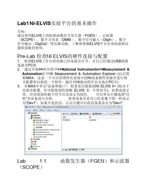
Pre-Lab 检查NI ELVIS的硬件连接与配置1. 检查ELVIS工作台的电源已经连接并打开,并且已经通过USB线缆连接至PC机2. 通过开始>>所有程序>>National Instruments>>Measurement &Automation打开NI Measurement & Automation Explorer (以后简称MAX,这是一个可以管理所有系统中的NI设备硬件资源并进行相关配置和自检的一个软件,随任何NI驱动程序会安装在PC中)3. 在MAX中单击“设备和接口”,检查是否能找到NI ELVIS II+ (取决于实验室配置, 有可能找到的是NI ELVIS II,不带加号),如果连接正常,应该前面的板卡符号应该显示为绿色. 可以单击右键选择“自检”对设备进行自检. 检查设备名是否已经是像下图一样显示为“Dev1”,如果不是的话,点击右键可以将设备重命名为“Dev1”.Lab 1.1 函数发生器(FGEN)和示波器(SCOPE)1. 用BNC接线将ELVIS工作台上的SCOPE CH0的BNC接口与原型板(Prototyping Board)上的BNC 1接口相连;在原型板的面包板上用导线将FGEN连接到BNC 1+2. 检查ELVIS工作台和Prototyping Board的电源均已开启. 然后通过Windows中的开始>>所有程序>>National Instruments>>NI ELVISmx for NI ELVIS & NI myDAQ>>NI ELVISmx Instrument Launcher打开NI ELVISmx Instrument Launcher3. 分别单击NI ELVISmx Instrument Launcher界面中的FGEN和SCOPE,打开信号发生器和示波器的软面板操作界面,按下图进行设置:通过函数发生器产生一个100Hz,峰峰值为4V的正弦信号,然后通过示波器进行观察. 由于我们连线时是通过原型板上的FGEN 接口连接至BNC1+,所以FGEN软面板下方Signal Route选项要选择Prototyping board. 选择之后点击Run按钮就会开始输出产生的信号波形;因为BNC1是连接到SCOPE的CH0,因此在示波器软面板中,应选择SCOPE CH0作为有效观测通道,然后点击示波器软面板的Run按钮应可观测到函数发生器产生的波形,如果没有正常显示应首先检查硬件连线和软件设置是否正确(注意检查PrototypingBoard的电源开关是否已经打开). 观测到正确波形后,可以尝试改变函数发生器产生的波形种类(如产生三角波或方波信号)及波形参数(频率、幅度、直流偏置等),并调整示波器软面板的波形显示参数,以便根据信号特征更好地进行显示.4. 在FGEN软面板中勾选手动模式(Manual Mode),观察ELVIS工作台右方FUNCTION GENERATOR区域中Manual Mode指示灯是否亮起;转动波形输出参数旋钮FREQUENCY(频率)或AMPLITUDE(幅度),在SCOPE窗口中观察输出波形的变化.5. 将连至原型板BNC 1接口的BNC接头拔下,与ELVIS工作台上的FGEN BNC接口连接;并将FGEN软面板窗口中的信号路径Signal Route设置为FGEN BNC,运行并观察结果. 此时的波形显示与之前并无二致,但是应理解此时的信号是直接经由ELVIS工作台底座的,并未经由ELVIS上的原型板,所以即使关闭原型板电源也可以.Lab 1.2 数字输入(DigIn)和数字输出(DigOut)1. 在原型板上用导线将DIO 0分别连接至DIO 8和LED 0;DIO 1分别连接至DIO 9和LED 1;依次连接,直至将DIO 7分别连接至DIO 15和LED 7. (如果时间有限,不一定8组都要连接,可只连接一两组)2. 单击NI ELVISmx Instrument Launcher中的DigIn和DigOut,打开数字输入(Digital Reader)和数字输出(Digital Writer)软面板. 按照下图设置参数(设置DIO 0-7为数字输出通道,DIO8-15为数字输入通道),点击运行按钮Run. 可以任意调整Digital Writer面板中的Manual Pattern,设置输出的数字电平高低,观察Digital Reader读取的数字量指示灯变化以及原型板右边LED指示灯区域的显示变化. Lab 1.3 二极管伏-安特性曲线测试1. 将被测二极管的长短针脚分别插入原型板的DUT+和DUT-接口2. 单击NI ELVISmx Instrument Launcher中的2-Wire,并按下图设置参数,运行即可测得该二极管的特性曲线Lab 1.4 (选作)使用ELVIS的数字万用表(DMM)1. 点击NI ELVISmx Instrument Launcher中的DMM打开数字万用表软面板,现在你就可以像使用任何数字万用表一样利用ELVIS工作台左侧的DMM接口和红黑香蕉线进行电压、电流或电阻的测量(注意:类似于其它数字万用表的使用,电流测量时红色香蕉线的连接与进行电压、电阻测量时不同).2. 用两根香蕉头线将ELVIS工作台的DMM V和COM接口分别连接至原型板的BANANA A和BANANA B接口,将Pt100 RTD温度传感器的两根线分别连至原型板面包板上的BANANA A和BANANA B.RTD3. 用LabVIEW打开练习文件夹\Exercise\ DMM RTD Meas下的DMMRTD Meas.vi,运行并观察结果;用手指捏住RTD,再观察结果. 4. RTD传感器的测量原理是通过测量传感器的电阻值从而通过换算得到温度值,在有效量程范围内,温度与电阻呈线性关系. 打开LabVIEW程序框图,了解如何在LabVIEW中编程以及显示ELVIS自带虚拟仪器所获得的数据并进行换算和显示,VI的前面板和程序框图如下图所示. 注意在LabVIEW程序中选择了ELVIS DMM的测量档位是“100Ohm”档,该RTD传感器的换算关系是阻值乘以3.5可得到摄氏温度,若选用的RTD传感器的换算关系与此不同,需要修改相应的系数因子.After Lab 清理实验台养成良好习惯,实验后将实验中所用到的导线等物品规整好,关闭ELVIS的电源以及计算机再离开实验室. 今后使用ELVIS的实验中都应注意这一点.。
基于改进的Yolov8商业渔船电子监控数据中鱼类的检测与识别
基于改进的Yolov8商业渔船电子监控数据中鱼类的检测与识别一、本文概述随着全球渔业资源的日益紧张,商业渔船的监管和资源保护变得尤为重要。
电子监控作为一种高效、实时的监管手段,正逐渐成为渔业管理的关键技术。
传统的电子监控数据分析主要依赖于人工审核,效率低下且易受主观因素影响。
开发一种自动化的鱼类检测与识别系统对于提高监管效率和保护渔业资源具有重要意义。
本文提出了一种基于改进的Yolov8算法的商业渔船电子监控数据中鱼类的检测与识别方法。
我们对Yolov8算法进行了改进,以适应复杂多变的海洋环境和渔船监控视频的特点。
改进包括网络结构的优化、损失函数的调整以及数据增强策略的应用。
我们构建了一个大规模的商业渔船监控视频数据集,用于模型的训练和测试。
数据集涵盖了多种海洋环境和鱼类种类,提高了模型的泛化能力。
实验结果表明,我们的方法在商业渔船电子监控数据中鱼类的检测与识别方面表现出色,显著提高了识别的准确率和效率。
本文的方法还具有较强的鲁棒性,能够适应不同的海洋环境和鱼类种类。
本研究的成功为商业渔船的电子监控数据分析提供了新的思路,有望为渔业资源的保护和管理提供有力支持。
二、商业渔船电子监控数据的概述随着现代渔业管理对可持续性和资源保护要求的不断提升,商业渔船已广泛采用先进的电子监控系统(Electronic Monitoring, EM)来替代或补充传统的船上观察员制度。
这些系统集成了多种传感器设备和视频记录技术,实时捕获并传输渔船作业过程中的丰富数据,为精确评估捕捞活动、保障海洋生物多样性及合规性监控提供了有力支持。
本节旨在对商业渔船电子监控数据进行概述,揭示其核心组成部分、采集方式以及在鱼类检测与识别中的关键作用。
船载摄像头:安置于渔船的关键作业区域,如甲板、渔获处理区、放网与收网处等,全天候记录高清晰度视频,直观展现捕捞操作、渔获种类与数量、尺寸分布等关键信息。
GPS定位系统:持续追踪渔船地理位置,确保捕捞活动发生在合法渔区,并记录渔船航行轨迹,用于分析捕捞行为的空间分布与时间模式。
电子捕鱼器的制作
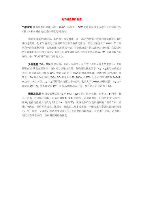
电子捕鱼器的制作工作原理捕鱼器是根据电压高于100V,功率大于30W的电能释放于水域中可击毙直径为1至1.5米水域内的鱼类的原理而制成的。
如捕鱼器电路图所示,电路由三部分组成:第一部分为晶体三极管和铁氧体变压器组成的逆变器,把12V直流电压变成数百至数千赫的交流电,其电压幅值大于100V;第二部分为全波倍压整流器,它把输出电压升高一倍,并变成直流,第三部分为继电器,它控制电路有效地把电能释放于水域,而且还可避免因插入水中而造成高压跌落。
W1可调节输入电流的大小,W2可调节输出功率的大小。
元件选择BG1、BG2要求对称,且用大功率管,每个管子要加足够大的散热片,变压器用E-20铁氧变压器芯,绕制时力求绝缘良好,各绕组数据见图示。
C1、C2采用油质纸介电容,继电器采用电压为12V,吸合电流小于40mA的直流继电器,电源用电压为12V,容量大于3A的小型蓄电池,BG1、BG2要求β≥50,BV ceo≥30V,另外可以代用的有3AD19、3AD30、3AD17等,D1、D2可用反向电压大于400V,电流大于200mA的整流管。
W1功率容量为2W,W2功率容量为1W。
开关K用触通式开关,允许通过的电流大于5A。
调整及使用电路安装毕后用40至60W、220V的灯泡作负载,接于A、B两端。
按下开关K,若电路不起振,可适当调换L1或L2的线头。
若电路起振,则可听到变压器声。
调W1使蓄电池输入电流为3.5至5A,再调W2,使继电器产生连续通断的“嗒嗒”声,此时灯泡闪亮,调整即告结束。
使用时,负载的二根多股皮线,一根接在用金属丝做的鱼网圈上,另一根接一金属板,将两根线放在1至1.5米宽的水域两端,可见水中冒泡,若有鱼,则被击昏浮于水面,然后用鱼网将鱼捞起。
电子捕鱼机的制作电子捕鱼器是将直流高压电能迅速释放到水中,将鱼击晕后捞捕的器具。
捕鱼器电路如下所示。
当开关SB按下时,由VT1,VT2,R1,L1,L2组成的自激振荡电路起振,可产生频率约2KHz的方波。
HiTECH PKK PKS 111 Level Switch Instruction Manual

INSTRUCTION MANUALHiTECH Technologies, Inc.301 Oxford Valley Road - Building 505A - Yardley, PA 19067-7706 Tel: 215. 321. 6012; Fax: 215. 321. 6067Tech Support (Toll Free) 866-DrLevel or 888-NIVELCOEmail:**********************@Web Site: or 1. APPLICATIONSThe devices are capable of operation in any one of the limit switch, window switch or differential switch modes. Accordingly, their potential applications include alarm switching, current range indication and performing empty/fill-type control functions.2. TECHNICAL DATAModel PKK-111PKS-111PKK-111PKS-111ConnectionDIN-rail type (EN 50 0222) 11-pin type (IEC 67-1-18a)Supply voltage230, 110, 24 VAC; 50 to 60 Hz or 24 V DC; -15to 10% Current input 0/5 mA or 0/20 mA;selectable Consumption 2.5 VA Adjustable range 0 to 6 mA or 0 to 26 mA Ambient temperature -10 to 55°C Overload capacity max. 100mA; continuousoverload EnclosureIP 40 Input impedance 132Ω (0/5 mA) 57Ω (0/20mA) Electrical protection Class II. Relay output SPTD; 250 V AC; 5 A Weight 0.21 kgSwitching delay approx.: 1 sec Mechanical life 2∗106 switching cycles Electrical life105 switching cycles3. ACCESSORIES User's manual4. OPERATIONThe current to be detected has to be applied as input to the "I in " terminals.In accordance with the settings, the input current is converted by the device into an output. The settings provided on the device are:5 mA 20 Input range selector:0 : 0/5 mA 1 : 0/20 mAA Operation mode selectorB Operation mode selectorCRelay mode selector see diagram 1 I A Switching level adjustment potentiometer I BSwitching level adjustment potentiometerThe switching values are set by the "I A " and "I B " multi-turn potentiometers.The operation mode selection is carried out by setting the "A" and "B" DIP-switches, according to table 2. The operation of the device is indicated via the "L1" green LED. The energised state of the relay is indicated via the "L2" yellow LED.Mode FunctionMode selector DIP-switchesCalibrationA BLA Limit switch with 1 0 I A LB 0.5% hysteresis 0 1 I B H Differential switch with adjustable hysteresis 1 1 I A and I B WWindow switchI A and I BMAINSOperating modes:• Selecting the LA or LB mode provides a limit switch function. These modes are equivalent, both represent the same function. The switching level in LA mode is set by the "I A " potentiometer, and in the LB mode by the "I B " potentiometer.• Selecting the H mode provides a differential switch function. The switching levels are set by the "I A " and "I B " potentiometers. There is no restriction as to which level should be larger. This mode can be used e.g. for pump controls.• Selecting the W mode provides a window switch function. The switching levels are set by the "I A " and "I B " potentiometers. There is no restriction as to which level should be larger. This mode is suitable to monitoring the current range and alarm switching, for instance:Suppose a transmitter with 4/20 mA current output is being used, failure indication is provided by the output changing to 22 mA; further, the wiring should be monitored for no breaks as well. Now; for instance, adjust the "I A " potentiometer to 22 mA (the failure current) and "I B " to 2 mA (indication of circuit break). With the relay mode set to C=0, the5. DIMENSIONS6. CALIBRATION6.1. Adjustments for the limit switch mode• Set the input range (0/5 or 0/20 mA).• Set the required mode (LA or LB) with the "A" and "B" DIP-switches. • Adjust the switching level with the corresponding potentiometer.6.2. Adjustments for the differential limit switch mode• Set the input range (0/5 or 0/20 mA).• Set the required mode (H) with the "A" and "B" DIP-switches.• Adjust the switching levels with the "I A " and "I B " potentiometers according to Figure 3.6.3. Adjustments for the window switch mode• Set the input range (0/5 or 0/20 mA).• Set the required mode (W) with the "A" and "B" DIP-switches.• Adjust the switching levels with the "I A " and "I B " potentiometers according to Figure 3.I INA1 1516 18 A2UU+_ I IN7. MAINTENANCE, REPAIRThe device does not require maintenance on a regular basis. Repairs under or out of guarantee are performed at the Manufacturer.8. STORAGE CONDITIONSEnvironment temperature: -13 to +140 °F (-25 to +60 °C)9. PERFORMANCE GUARANTEESince 1986, every instrument sold by HiTECH has been guaranteed to perform in the application it originally was engineered and recommended for. Our company policy remains the same, every product sold comes with a written performance guarantee.Should the equipment be unable to perform satisfactorily in your application and we are not able to correct the problem, we will accept the instrument in return and issue full credit.This performance guarantee is valid for 60 days. Thereafter, our standard limited two years factory warranty goes into effect.HiTECH Technologies, Inc.301 Oxford Valley Road - Building 505A - Yardley, PA 19067-7706 Tel: 215. 321. 6012; Fax: 215. 321. 6067Tech Support (Toll Free) 866-DrLevel or 888-NIVELCOEmail:**********************@Web Site: or 。
卡梅伦液压数据手册(第 20 版)说明书
iv
⌂
CONTENTS OF SECTION 1
☰ Hydraulics
⌂ Cameron Hydraulic Data ☰
Introduction. . . . . . . . . . . . . ................................................................ 1-3 Liquids. . . . . . . . . . . . . . . . . . . ...................................... .......................... 1-3
4
Viscosity etc.
Steam data....................................................................................................................................................................................... 6
1 Liquid Flow.............................................................................. 1-4
Viscosity. . . . . . . . . . . . . . . . . ...................................... .......................... 1-5 Pumping. . . . . . . . . . . . . . . . . ...................................... .......................... 1-6 Volume-System Head Calculations-Suction Head. ........................... 1-6, 1-7 Suction Lift-Total Discharge Head-Velocity Head............................. 1-7, 1-8 Total Sys. Head-Pump Head-Pressure-Spec. Gravity. ...................... 1-9, 1-10 Net Positive Suction Head. .......................................................... 1-11 NPSH-Suction Head-Life; Examples:....................... ............... 1-11 to 1-16 NPSH-Hydrocarbon Corrections.................................................... 1-16 NPSH-Reciprocating Pumps. ....................................................... 1-17 Acceleration Head-Reciprocating Pumps. ........................................ 1-18 Entrance Losses-Specific Speed. .................................................. 1-19 Specific Speed-Impeller. .................................... ........................ 1-19 Specific Speed-Suction...................................... ................. 1-20, 1-21 Submergence.. . . . . . . . . ....................................... ................. 1-21, 1-22 Intake Design-Vertical Wet Pit Pumps....................................... 1-22, 1-27 Work Performed in Pumping. ............................... ........................ 1-27 Temperature Rise. . . . . . . ...................................... ........................ 1-28 Characteristic Curves. . ...................................... ........................ 1-29 Affinity Laws-Stepping Curves. ..................................................... 1-30 System Curves.. . . . . . . . ....................................... ........................ 1-31 Parallel and Series Operation. .............................. ................. 1-32, 1-33 Water Hammer. . . . . . . . . . ...................................... ........................ 1-34 Reciprocating Pumps-Performance. ............................................... 1-35 Recip. Pumps-Pulsation Analysis & System Piping...................... 1-36 to 1-45 Pump Drivers-Speed Torque Curves. ....................................... 1-45, 1-46 Engine Drivers-Impeller Profiles. ................................................... 1-47 Hydraulic Institute Charts.................................... ............... 1-48 to 1-52 Bibliography.. . . . . . . . . . . . ...................................... ........................ 1-53
打鱼机程序原理 揭秘

打鱼机程序原理揭秘
打鱼机程序原理是基于计算机图像识别技术的。
首先,程序会通过摄像头捕捉到打鱼机的画面。
接下来,程序会对捕捉到的画面进行图像处理,将其转化为计算机可以识别和分析的数据。
然后,程序会使用图像识别算法来检测鱼的位置和类型。
这通常涉及到边缘检测、颜色分析等技术。
根据鱼的位置和类型,程序会计算出最佳的打击点和力度。
最后,程序会通过控制机械臂或其他打击装置,实现对鱼的打击。
整个过程中,程序需要不断地更新和优化图像处理和分析算法,以提高打击的准确性和效率。
数据通信原理实验指导书
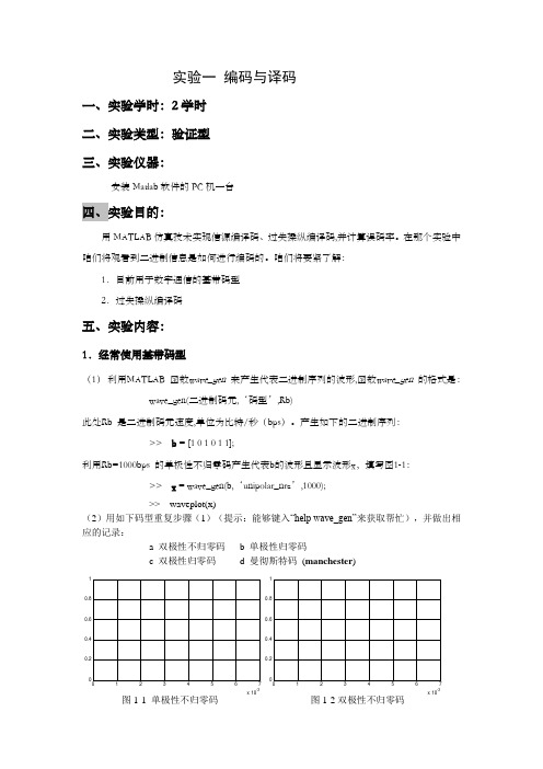
实验一编码与译码一、实验学时:2学时二、实验类型:验证型三、实验仪器:安装Matlab软件的PC机一台四、实验目的:用MATLAB仿真技术实现信源编译码、过失操纵编译码,并计算误码率。
在那个实验中咱们将观看到二进制信息是如何进行编码的。
咱们将要紧了解:1.目前用于数字通信的基带码型2.过失操纵编译码五、实验内容:1.经常使用基带码型(1)利用MATLAB 函数wave_gen 来产生代表二进制序列的波形,函数wave_gen 的格式是:wave_gen(二进制码元,‘码型’,Rb)此处Rb 是二进制码元速度,单位为比特/秒(bps)。
产生如下的二进制序列:>> b = [1 0 1 0 1 1];利用Rb=1000bps 的单极性不归零码产生代表b的波形且显示波形x,填写图1-1:>> x = wave_gen(b,‘unipolar_nrz’,1000);>> waveplot(x)(2)用如下码型重复步骤(1)(提示:能够键入“help wave_gen”来获取帮忙),并做出相应的记录:a 双极性不归零码b 单极性归零码c 双极性归零码d 曼彻斯特码(manchester)x 10-3x 10⁻³图1-1 单极性不归零码图1-2双极性不归零码x 10-3x 10-32.过失操纵编译码(1) 利用MATLAB 函数encode 来对二进制序列进行过失操纵编码, 函数encode 的格式是:A .code = encode(msg,n,k,'linear/fmt',genmat)B .code = encode(msg,n,k,'cyclic/fmt',genpoly)C .code = encode(msg,n,k,'hamming/fmt',prim_poly)其中A .用于产生线性分组码,B .用于产生循环码,C .用于产生hamming 码,msg 为待编码二进制序列,n 为码字长度,k 为分组msg 长度,genmat 为生成矩阵,维数为k*n ,genpoly 为生成多项式,缺省情形下为cyclpoly(n,k)。
鱼类X射线图像增强算法研究

特沃斯高通滤波器等。在此基础上,文章提出了计算像素点局部邻域内的最大值和最小值,并利用最大值和最小值得到自适应
参数,建立对比度增强函数,并利用该函数公式增强图像。实验结果表明,文章提出的方法能有效提取鱼类 X 射线图像中的鱼
刺,具有较好的视觉效果。
关键词:X 射线图像;图像增强;高通滤波器;直方图均衡
h
(x,
y)
e-
x
2 y2 22
,
(2)
其中,x 和 y 分别表示点的 x 坐标和 y 坐标。滓 为标准差。 如果要将式(2)用于图像滤波,由于图像是离散的二维数 据,因此,需要将式(2)离散化,一般可以表示为 3伊3 或 5伊5 等形式。
对图像进行高斯滤波之后,将滤波后的图像再进行 以下操作:
步骤 1:计算图像中各像素邻域内的灰度最大值 max 和最小值 min。
渊上接 5 页冤
[10]刘树军,王颖,许志坤.大数据视角下邮政企业教育培训用户画像 研究与应用[J].邮政研究,2019,35(6):36-38. [11]刘海鸥,姚苏梅,黄文娜,等.基于用户画像的图书馆大数据知识 服务情境化推荐[J].图书馆学研究,2018(24):57-63+32. [12]王飞飞,周少华,韩迎军.基于大数据技术的电力用户画像分析[J]. 山西电力,2019(4):26-29. [13]徐涛,黄莉,李敏蕾,等.基于多维细粒度行为数据的居民用户画 像方法研究[J].电力需求侧管理,2019,21(3):47-52+58. [14]葛晓鸣.基于“用户画像”模型构建的精准营销策略[J].辽东学院学 报(社会科学版),2019,21(4):50-57. [15]陈丹,柳益君,罗烨,等.基于用户画像的图书馆个性化智慧服务 模型框架构建[J].图书馆工作与研究,2019(6):72-78.
改进YOLOv8的输电线路异物检测方法

改进YOLOv8的输电线路异物检测方法目录一、内容概括 (2)1. 背景介绍 (2)2. 研究目的和意义 (3)二、YOLOv8概述 (4)1. YOLOv8发展历程 (4)2. YOLOv8特点分析 (6)三、输电线路异物检测现状分析 (7)1. 传统检测方法概述 (8)2. 现有检测方法存在的问题 (9)四、改进YOLOv8的输电线路异物检测方法 (9)五、实施细节与关键步骤 (10)1. 硬件平台与环境搭建 (11)2. 软件平台与开发工具选择 (12)3. 具体实施步骤与流程 (14)六、性能评估与对比分析 (15)1. 性能评估指标及方法 (15)2. 与传统方法及其他算法对比 (16)3. 检测结果分析 (17)七、实际应用与案例分析 (19)1. 在输电线路异物检测中的应用 (20)2. 案例分析 (21)3. 效果展示与讨论 (22)八、总结与展望 (23)1. 研究成果总结 (24)2. 存在问题及挑战分析 (25)3. 未来研究方向与展望 (26)一、内容概括引入先进的深度学习技术,如ResNet和DenseNet,以增强模型的特征提取能力。
采用迁移学习的方法,利用在大规模数据集上预训练的模型进行微调,以提高模型的泛化能力。
针对输电线路异物的特点,设计了一种新的数据增强技术,以扩大训练数据的多样性。
1. 背景介绍随着智能化时代的快速发展,电力系统的安全性与稳定性在人们的日常生活和经济建设中起着举足轻重的作用。
而输电线路作为电力系统的关键组成部分,其运行安全直接关系到整个电网的可靠性。
输电线路异物检测是保障其安全运行的重要手段之一,传统的检测方式主要依赖于人工巡检,这种方式不仅效率低下,而且容易受天气、环境等因素影响,存在一定的安全隐患。
开发高效、准确的输电线路异物检测方法显得尤为重要。
随着计算机视觉技术的飞速发展和深度学习理论的完善,目标检测技术在各领域得到了广泛应用。
YOLO(You Only Look Once)系列算法作为目标检测领域的重要分支,以其快速、准确的检测性能受到了广泛关注。
打鱼机内部程序原理
打鱼机内部程序原理
打鱼机内部程序原理是通过一系列的算法和逻辑来模拟传统打鱼游戏。
该程序主要由以下几个部分组成:
1. 游戏画面生成:程序会根据预设的背景和鱼群动画效果,绘制出游戏画面。
这些背景和动画通常是事先设计好的,然后通过程序来实时渲染出来。
2. 鱼群生成:程序会生成众多的鱼群,并使它们在游戏画面中移动。
每个鱼群都有自己的属性,如大小、速度、颜色等,并根据一定的规则更新其位置和状态。
3. 炮台控制:程序会监听玩家的操作,根据玩家的指令来控制炮台的角度和能量。
炮台的角度决定了发射的方向,能量决定了发射的威力。
4. 碰撞检测:程序会判断玩家发射的子弹是否与鱼群相交,如果相交,则表示击中了鱼群。
碰撞检测的过程通常使用数学算法,如线段相交、距离计算等。
5. 得分计算:当玩家成功击中一条鱼群时,程序会根据鱼群的属性和玩家发射的炮弹威力,计算出相应的得分。
得分的计算方式可以根据游戏设定的规则进行调整。
6. 界面更新:程序会实时更新游戏画面上的信息,包括玩家的得分、剩余子弹数量等。
同时,还会根据玩家的得分情况来调整游戏难度,例如增加鱼群的数量或速度。
通过上述程序设计,打鱼机可以实现传统打鱼游戏的娱乐效果,给玩家带来快感和挑战。
IZE11模拟输出仪器说明书

NoteFollow the instructions given below when operating the electrostatic sensor monitor.Otherwise, the electrostatic sensor monitor may be damaged or may fail, thereby resulting in malfunction.•Do not pull the lead wire forcefully, or lift the product by pulling the lead wire.•Do not use in a place where oil or chemical splashes may occur.•Connect Terminal FG to the ground when using a switching regulator obtained on the commercial market.•Insert a noise filter (line noise filter, ferrite element or other element)between the switching regulator and monitor when analog output is used.•Do not press the buttons with a sharp pointed object.•To measure small electric potential, 20 to 30 min. of warm-up time is necessary. Initial drift of about ±1% F.S. occurs immediately after turning the power on.•Start measurement by the monitor 3s after turning the power on.Measurement output will be inaccurate for the first 3s.•The direct-current power supply to combine should use ULauthorization power supply which is the class 2 power supply based on UL1310 or the power supply is using the transformer of a class 2based on UL1585.•Electrostatic sensor or monitor will not withstand lightning surges.Protection against it must be provided for the device.•Do not turn off the power supply while setting functions to avoid storing of incorrect values or settings.IZE11-TFK08GB-AInstallation & Maintenance Manual Electrostatic Sensor Monitor Series IZE11•This manual contains essential information for the protection of users and others from possible injury and/or equipment damage.•Read this manual before using the product, to ensure correct handling,and read the manuals of related apparatus before use.•Keep this manual in a safe place for future reference.•These instructions indicate the level of potential hazard by label of “DANGER”, “WARNING” or “CAUTION”, followed by important safety information which must be carefully followed.•To ensure safety of personnel and equipment the safety instructions in this manual and the product catalogue must be observed, along with other relevant safety practices.WARNING•Do not disassemble, modify (including change of printed circuit board) or repair the product.An injury or product failure may result.•Do not operate the product beyond the specification range.Fire, malfunction or equipment damage may result. Use the product only after confirming the specifications.•Do not use the product in the presence of flammable, explosive or corrosive gas.Fire, explosion or corrosion may result. This product does not have an explosion proof construction.•When using the product as part of an interlocking system:1) Provide a double interlocking system, for example a mechanical system.2) Check the product regularly to ensure proper operation.•Before performing maintenance, be sure of the following:1) Turn off the power supply.•Sensor to connect must be selected.Actual potential can not be displayed unless selected value of the connect sensor is correctly set.At initial setting or when sensor connected, ensure the selected value of the connected sensor and the type of used electrostatic sensor are matched.•Always perform a system check after maintenance.Do not use the product if any error occurs.Safety cannot be assured if caused by un-intentional malfunction.•Provide grounding to ensure correct operation and to improve noise resistance of the product.This product should be individually grounded using a short cable.•Follow the instructions given below when handling the product.Failing to do so may result in product damage.• Maintenance space should always be provided around the product.• Do not remove labels from the product.• Do not drop, hit or apply excessive shock to the product.•Follow all specified tightening torques.• Do not bend, apply tensile force, or apply force by placing heavy loads,on the cables.• Connect wires and cables correctly, and do not connect while the power is ON.• Do not route wires and cables together with power or high-voltage cables.• Check the insulation of wires and cables.• Take proper measures against noise, such as noise filters, when the product is incorporated in equipment or devices.• Select the required protection (IP) rating according to the environment of operation.• Take sufficient shielding measures when the product is to be used in the following conditions:(1) where noise due to static electricity is generated.(2) where electro-magnetic field strength is high.(3) where radioactivity is present.(4) where power lines are located.• Do not use the product in a place where electric surges are generated.• Use suitable surge protection when a surge generating load such as a solenoid valve are to be directly driven.• Prevent any foreign matter from entering this product. • Do not expose the product to vibration or impact.• Use the product within the specified ambient temperature range.• Do not expose the product to any heat radiation.• Do not clean the product with chemicals such as benzene or thinners.IZE11-4 Mounting and InstallationM3 5LPanel mount adapter (Type ZS-27-C)M3 8LPanel mount adapter can be attached alsoin the position turned 90 degrees.Mounting•Mount the optional bracket and panel mount adapter to the controller.Mounting by bracket•Fix the bracket to the controller with the set screws M35L (2pcs.) as attached.•The tightening torque of the set screws must be 0.5 to 0.7N∙m.Mounting by Panel mount adapter•Fix the panel mount adapter to the controller with the set screws M38L (2pcs.) as attached.Note1) Rated value when the distance between charged object and the sensor is 25mm.Note2) Rated value when the distance between charged object and the sensor is 50mm.CAUTIONbuttonbutton button6 Names / Functions of individual Parts7 Internal Circuit and WiringConductor size : 0.14mm 2 to 0.2mm 2Overall diameter : 0.8 to 1.0BracketOutput (OUT1) display (Green) : Lit when OUT1 is ON.Output (OUT2) display (Red) : Lit when OUT2 is ON.LCD display : Displays the current status of charged potential, set modecondition and error code. Four display modes can be selected display always in red or green only, or changing from green to red linked to output.button : Selects a mode and increases a set ON/OFF value. Press thisbutton to change to the peak display mode.button : Selects a mode and decreases a set ON/OFF value. Pressthis button to change to the bottom display mode.button : Changes the mode and sets a set value.OptionsPower and output lead wire with cable (2m) : ZS-28-A Connector for sensor lead wire (1pc.) : ZS-28-CBracket with set screws M35L (2pcs.) : ZS-28-BPanel mount adapter with set screws M38L (2pcs.) : ZS-27-CPanel mount adapter with set screws M38L (2pcs.)+Front face protective cover : ZS-27-DFront face protective cover : ZS-27-010)Panel Hole Dimensions Panel Thickness : 0.5 to 6mm)0)Two or more in rown : The number of controllers SeparateHorizontalVerticalAttaching the connector to the lead wire •Strip the sensor wire as shown in the figure.(Do not strip the cable wire sheath)•The core of the corresponding color shown in the following table is put into the correct pin number printed on the connector and pushed to the back.•The centre part A is pushed straight in using a suitable tool, such as pliers.•Re-use cannot be performed once the connector has been closed completely.When connection failure occurs such as incorrect fitting of wires, or incomplete insertion, please use a new connector.(The shield wire is common with amplifier case. Frame ground should be prepared at the amplifier case side.)Connection•Make connection after turning the power off.•Install the lead wire separately from the route for power cable or high-voltage cable. Otherwise, malfunction may potentially result due to noise.•Be sure to ground Terminal FG when using a switching regulator obtained on the commercial market. If analogue output is performed connecting to a switching regulator obtained on the market, switching noise will be superimposed and product specification can no longer be met. This can be prevented by inserting a noise filter, such as a line noise filter and a ferrite element, between the switching regulator and the controller, or by using a series power supply instead of a switching regulator.•Check that the above-mentioned preparation work has been performed correctly, and A part shown in the figure is pushed by hand and makes temporary connection.Connector Connecting/Disconnecting•When connecting the connector, insert it straight onto the pin holding the lever and connector body and lock the connector by pushing the lever claw into the square groove in the housing until connector clicks.•When disconnecting the connector, push down the lever to disengage the lever claw from the square groove. Then pull the connector straight out.DC(-) Analogue OUT2 OUT1 Power and Output Connector Pin numbersNote) When R is required, specifyR2 or less.IZE112PNP Open Collector Output :2 OutputsMax. 80mAResidual voltage 1V or less Analogue Output : 1 to 5V Output Impedance :Approx.1kΩIZE113PNP Open Collector Output :2 Outputs Max. 80mA Residual voltage 1V or less Analogue Output : 4 to 20mA Max. Load Impedance :600Ω(@ 24VDC)Min. Load Impedance :50ΩOutput SpecificationWhen the SMC power and output lead wire (type ZS-28-A) is used, the colors of wire (Brown, Black, White, Grey, Blue) will apply as shown on the circuit diagram.IZE110NPN Open Collector Output :2 OutputsMax. 30V, 80mA Residual voltage 1V or lessAnalogue Output : 1 to 5VOutput Impedance :Approx. 1kΩIZE111NPN Open Collector Output :2 OutputsMax. 30V, 80mA Residual voltage 1V or less Analogue Output : 4 to 20mA Max. Load Impedance:600Ω(@ 24VDC)Min. Load Impedance:50ΩAUSTRIA (43) 2262 62280 NETHERLANDS (31) 20 531 8888 BELGIUM (32) 3 355 1464 NORWAY (47) 67 12 90 20 CZECH REP.(420) 541 424 611POLAND (48) 22 211 9600 DENMARK (45) 7025 2900 PORTUGAL (351) 21 471 1880FINLAND (358) 207 513513 SLOVAKIA (421) 2 444 56725 FRANCE (33) 1 6476 1000 SLOVENIA (386) 73 885 412GERMANY (49) 6103 4020 SPAIN (34) 945 184 100 GREECE (30) 210 271 7265 SWEDEN(46) 8 603 1200 HUNGARY (36) 23 511 390 SWITZERLAND (41) 52 396 3131 IRELAND (353) 1 403 9000 UNITED KINGDOM(44) 1908 563888ITALY(39) 02 92711URL (Global) (Europe)Specifications are subject to change without prior notice from the manufacturer. © SMC Corporation All Rights Reserved.8 Contacts。
- 1、下载文档前请自行甄别文档内容的完整性,平台不提供额外的编辑、内容补充、找答案等附加服务。
- 2、"仅部分预览"的文档,不可在线预览部分如存在完整性等问题,可反馈申请退款(可完整预览的文档不适用该条件!)。
- 3、如文档侵犯您的权益,请联系客服反馈,我们会尽快为您处理(人工客服工作时间:9:00-18:30)。
Course: DT5721Instructors: Fredrik Jönsson Distributed Systems and SecurityLaboratory 1: DESLab Group: 1Dian Yu, Qiang HuangLaboratory Date: Nov 30, 2010Approved by ___________Date: ___________Contents1. Introduction 32. Results of Running Example Program 4 2.1 Program function and related concepts 42.2 Running results 63. Program Development and Running Result 7 3.1 Program development 7 3.2 Running results 9 Appendix 101.IntroductionThe Data Encryption Standard (DES) is a block cipher that uses shared secret encryption. It was selected by the National Bureau of Standards as an official Federal Information Processing Standard (FIPS) for the United States in 1976 and which has subsequently enjoyed widespread use internationally. It is based on a symmetric-key algorithm that uses a 56-bit key. The algorithm was initially controversial with classified design elements, a relatively short key length, and suspicions about a National Security Agency (NSA) backdoor. DES consequently came under intense academic scrutiny which motivated the modern understanding of block ciphers and their cryptanalysis.2.Results of Running Example ProgramThis chapter will discuss concepts relating with the example program, and also the result.2.1 Program functions and related conceptsFigure 1 shows how the DES works, A block to be enciphered is subjected to an initial permutation IP, then to a complex key-dependent computation and finally to a permutation which is the inverse of the initial permutation IP-1.The 64 bits of the input block to be enciphered are first subjected to the following permutation, called the initial permutation IP:That is the permuted input has bit 58 of the input as its first bit, bit 50 as its second bit, and so on with bit 7 as its last bit. The permuted input block is then the input to a complex key-dependent computation described below. The output of that computation, called the preoutput, is then subjected to the following permutation which is the inverse of the initial permutation:Let the 64 bits of the input block to an iteration consist of a 32 bit block L followed by a 32 bit block R. Using the notation defined in the introduction, the input block is then LR.Let K be a block of 48 bits chosen from the 64-bit key. Then the output L'R' of an iteration with input LR is defined by:L' = RR' = L ○+ f(R,K)With more notation we can describe the iterations of the computation in more detail. Let KS be function which takes an integer n in the range from 1 to 16 and a 64-bit block KEY as input and yields as output a 48-bit block Kn which is a permuted selection of bits from KEY. That isKn = KS(n,KEY)2.2 Running resultsThe result of the example program is showed below.3.Program Development and Running ResultThis chapter will show the development of the example program, and also the result.3.1 Program developmentAs the requirement, what we need to do is to complete the encryption, decryption and the F function party in the example code.EncryptionAs following the description, at first, The 64 bits of the input block to be enciphered are first subjected to the initial permutation (IP).applyIP(plaintext,ciphertext); //start by apply IPThe calculation of f(R,K), put the output at TempData2F(RTemp, roundKeys[r], TempData2);and then, perform an bitwise xor operation between the left part (LTemp) and the TempData2.TempData2[0] = TempData2[0] ^ *LTemp;TempData2[1] = TempData2[1] ^ *(LTemp+1);TempData2[2] = TempData2[2] ^ *(LTemp+2);TempData2[3] = TempData2[3] ^ *(LTemp+3);At last, exchange the left and right part.memcpy(LTemp, RTemp, 4);memcpy(RTemp, TempData2, 4); //update R and LDo the same work 16 times.for(r=1;r<=16;r++)apply inverse IPapplyInvIP(TempData , ciphertext);DecryptionThe only difference from encryption is K16 is used in the first iteration, K15 in the second, and so on, with K1 used in the 16th iteration.So, we just need to let roundKeys[16] to calculate with RTemp at first when doingt the 16 iterations.for(r=1;r<=16;r++){//call F, use correct roundKeyF(RTemp, roundKeys[17-r], TempData2);F functionA sketch of the calculation of f(R,K) is given in Figure 2.Let E denote a function which takes a block of 32 bits as input and yields a block of 48 bits as output. Let E be such that the 48 bits of its output, written as 8 blocks of 6 bits each, are obtained by selecting the bits in its inputs in order according to the following table:So, according to this, the function below is uesd for expand the input to 48 bit. applyE(R, ExpandArea); //expand R to 48-bitsand then, perform an bitwise xor operation between the ExpanArea and the sub-key(roundKeys[i]).for(i = 0; i < 6; i++){ExpandArea[i] = ExpandArea[i] ^ *(roundKey+i); //xor with roundKey }The output of the xor will have a complicated calculation with Sbox, here, we just need to call the function named SBox() which has already defined before.SBox(ExpandArea, TempOut); //call SBoxThe result is 48 bit, so we need use pbox to transform it to 32 bitapplyP(TempOut, output); //call final permutation3.2 Running resultsThe result of the program about encryption and decryption is showed below.AppendixPart of Code(which is modified by ourselves): des.c/*--------------YOU SHOULD IMPLEMENT encrypt, decrypt, and F ----------*/ byte* encrypt(byte* plaintext,byte** roundKeys){/*encrypt plaintext, using the roundKeys*/byte* ciphertext;int r; //Loop Variable to Keep track of Roundschar TempData[8];char TempData2[4];char *LTemp = TempData; /* left 4 bytes (half) of the data block. */char *RTemp = &(TempData[4]); /* right half of the ciphertext block. */ //allocate memory for ciphertextciphertext=calloc(8,sizeof(byte));if( NULL == ciphertext){printf("Memory Allocation Failed \n");return NULL;}//start by apply IPapplyIP(plaintext,ciphertext);//initiate L and Rmemcpy(TempData, ciphertext, 8);//iterate 16 rounds in DESfor(r=1;r<=16;r++){//call F, use correct roundKeyF(RTemp, roundKeys[r], TempData2);//xor with LTempData2[0] = TempData2[0] ^ *LTemp;TempData2[1] = TempData2[1] ^ *(LTemp+1);TempData2[2] = TempData2[2] ^ *(LTemp+2);TempData2[3] = TempData2[3] ^ *(LTemp+3);//update R and Lmemcpy(LTemp, RTemp, 4);memcpy(RTemp, TempData2, 4);}TempData2[0] = TempData[0];TempData2[1] = TempData[1];TempData2[2] = TempData[2];TempData2[3] = TempData[3];TempData[0] = TempData[4];TempData[1] = TempData[5];TempData[2] = TempData[6];TempData[3] = TempData[7];TempData[4] = TempData2[0];TempData[5] = TempData2[1];TempData[6] = TempData2[2];TempData[7] = TempData2[3];//apply inverse IPapplyInvIP(TempData , ciphertext);return ciphertext;}byte* decrypt(byte* ciphertext,byte** roundKeys){/*decrypts plaintext, using the roundKeys*/byte* plaintext;int r;char TempData[8];char TempData2[4];char *LTemp = TempData; /* left 4 bytes (half) of the data block. */ char *RTemp = &(TempData[4]); /* right half of the ciphertext block. */ //allocate memory for plaintextplaintext=calloc(8,sizeof(byte));//start by apply IPapplyIP(ciphertext,plaintext);//initiate L and Rmemcpy(TempData, plaintext, 8);//iterate 16 roundsfor(r=1;r<=16;r++){//call F, use correct roundKeyF(RTemp, roundKeys[17-r], TempData2);//xor with LTempData2[0] = TempData2[0] ^ *LTemp;TempData2[1] = TempData2[1] ^ *(LTemp+1);TempData2[2] = TempData2[2] ^ *(LTemp+2);TempData2[3] = TempData2[3] ^ *(LTemp+3);//update R and Lmemcpy(LTemp, RTemp, 4);memcpy(RTemp, TempData2, 4);}TempData2[0] = TempData[0];TempData2[1] = TempData[1];TempData2[2] = TempData[2];TempData2[3] = TempData[3];TempData[0] = TempData[4];TempData[1] = TempData[5];TempData[2] = TempData[6];TempData[3] = TempData[7];TempData[4] = TempData2[0];TempData[5] = TempData2[1];TempData[6] = TempData2[2];TempData[7] = TempData2[3];//apply inverse IPapplyInvIP(TempData , plaintext);return plaintext;}void F(byte* R,byte* roundKey,byte* output){/*The function F in DES */byte ExpandArea[6];byte TempOut[8];int i;//expand R to 48-bitsapplyE(R, ExpandArea);//xor with roundKeyfor(i = 0; i < 6; i++){ExpandArea[i] = ExpandArea[i] ^ *(roundKey+i);}//call SBoxSBox(ExpandArea, TempOut);//call final permutationapplyP(TempOut, output);}/*-----YOU DO NOT NEED TO MODIFY THE FOLLOWING METHODS--------*/。
