Qos provisioning using a clearing house architecture
H3C-5120交换机QoS配置
H3C-5120交换机QoS配置1. 介绍QoS(Quality of Service)是为了保证网络传输中的数据流能满足特定的服务需求而采取的一系列技术措施。
本文档将介绍如何在H3C-5120交换机上进行QoS配置。
2. 配置步骤步骤1:登录交换机使用管理员账户登录到交换机的CLI界面。
步骤2:创建QoS策略使用以下命令创建一个新的QoS策略:<H3C-5120> system-view[H3C-5120] qos policy policy1[H3C-5120-policy-qos-policy-policy1] quit步骤3:配置流量分类使用以下命令创建流量分类,并将其应用于刚创建的QoS策略:[H3C-5120] traffic classifier classifier1[H3C-5120-classifier-classifier1] if-match ipv4 source-address10.0.0.0 0.255.255.255[H3C-5120-classifier-classifier1] quit[H3C-5120] qos policy policy1[H3C-5120-policy-qos-policy-policy1] classifier classifier1 behavior behavior1[H3C-5120-policy-qos-policy-policy1-classifier-classifier1-behavior-behavior1] quit步骤4:配置流量行为使用以下命令配置流量行为,并将其应用于刚创建的QoS策略:[H3C-5120] traffic behavior behavior1[H3C-5120-behavior-behavior1] remark dscp 24[H3C-5120-behavior-behavior1] quit步骤5:应用QoS策略使用以下命令将QoS策略应用于某个接口:[H3C-5120] interface gigabitethernet 1/0/1[H3C-5120-GigabitEthernet1/0/1] qos apply policy policy1 inbound[H3C-5120-GigabitEthernet1/0/1] quit步骤6:保存配置使用以下命令保存配置并退出:[H3C-5120] save[H3C-5120] quit3. 总结通过以上配置步骤,我们可以在H3C-5120交换机上成功配置QoS。
Best Known Method for Provisioning-Unattended Install LD88
LANDesk® Management Suite 8.8 Best Practices for Provisioning – Unattended InstallContentsSummary (4)Assumptions (4)Advantages of Provisioning (4)Automating Provisioning (5)Deploying a PXE representative (5)Steps to deploy the PXE Representative (5)About Templates (6)About Provisioning Agent (6)Unattended Install (7)Provisioning History (20)Adding a bare metal device (21)Provisioning Rights (22)Conclusion (22)References (22)Acronyms (22)About LANDesk Software (23)Author (23)This document contains confidential and proprietary information of LANDesk Software, Inc. and its affiliates (collectively “LANDesk”) and is provided in connection with the identified LANDesk® product(s). No part of this document may be disclosed or copied without the prior written consent of LANDesk. No license, express or implied, by estoppel or otherwise, to any intellectua l property rights is granted by this document. Except as provided in LANDesk’s terms and conditions for the license of such products, LANDesk assumes no liability whatsoever. LANDesk products are not intended for use in medical, life saving, or life sustaining applications. LANDesk does not warrant that this material is error-free, and LANDesk reserves the right to update, correct, or modify this material, including any specifications and product descriptions, at any time, without notice.Copyright © 2007, LANDesk Software Ltd. All rights reserved.LANDesk and Targeted Multicast are trademarks or registered trademarks of LANDesk Software, Ltd. and its affiliated companies in the United States and other countries. Other brands and names may be claimed as the property of others.LSI-0614 04/07 JBB/NHThe purpose of this document is to provide a simple approach to setting up and configuring LANDesk® Provisioning for an unattended installation of Windows XP. LANDesk® Provisioning provides a new way to completely install and configure your desktops and servers—from OS installation to application deployment, patching and configuration—all using a single provisioning task. LANDesk Provisioning was built with the IT administrator’s environment and workflow in mind, providing the standardization and repeat ability you need, while allowing for the customization and flexibility you must have to meet your end users’ needs.LANDesk provisioning allows you to split the provisioning tasks the way you split the work when you’re setting up a system manually now. You can:Plan and assess the needsDesign and test the system configurationDeploy to one or to a group of systemsCreate reusable ―building block‖ tasks for common operationsPerform post-OS tasks, such as installing applications, updating the virus definitions file, and updating the OS with patches Ensure the installation worked, perhaps by running sample test applications.You can schedule a provisioning task in advance—even before the hardware arrives on site—or run it dynamically when needed, such as when a system fails and needs to be restored in-line.Provisioning consists of defining the attributes and features to be applied to targeted servers via automation. This is done through provisioning templates. A template is a series of building blocks to be applied to a device. They build upon each other, and can consist of actions, attributes, constraints, and so forth. A template can have one or many actions. Templates can be re-used, and components of a template can be copied to another. LANDesk provides some canned templates for you to download to modify for your environment.Note: This document is not a complete source of all LANDesk provisioning information. For more detailed information, please see the online help when using your LANDesk management solution.AssumptionsThis paper assumes that the reader has a working knowledge of LANDesk® Management Suite, its functionality, profile migration and operating system deployment methods.Advantages of ProvisioningLANDesk Provisioning offers several advantages over the current practice of manual installs or creating and managing a library of images for new devices. Provisioning defines a series of actions and attributes that are applied to a device dynamically, known as templates. Templates can be defined in either large or small portions and can be combined together to be customized for different hardware and application-types.Creating multiple custom templates using LANDesk’s provisioning capabilities is faster and easier than creating multiple cust om images. Say you have to create 30 unique configurations for your environment. Since templates are formatted as XML documents, and actions can be shared between templates, you can easily review and edit templates for consistency rather than rebuilding or recapturing 30 unique images. For example, if you create an action that installs the virus scanner and updates definitions, you can share this action with each of the 30 templates.If you have a library of images already created, LANDesk provisioning can make use of those images, then script actions before the image deployment—such as waking and booting a remote device—and after the image—such as downloading updated definitions files and OS updates.Templates can be created and scheduled in advance—before the hardware arrives on site. Because each system is unique, sharing a general image between systems can lead to performance and compatibility issues that scripted installs can overcome, so doing this kind of pre-arrival prep work with images. Further, by combining various ―building block‖ templates, new templates can quickly and easily be created and customized to meet a system’s exact requirements.Automating ProvisioningManual provisioning traditionally offers some advantages to the IT administrator, allowing him or her to handle odd error conditions or find needed device drivers so the IT admin is assured of a successfully provisioned device, rather than devoting hours to programming ultra-complex custom scripts that may yield little return when the time spent programming and troubleshooting the scripts is taken into account.When you have only a few devices coming online every month or you have a store of images to go on several identical devices, a manual or semi-automated provisioning process can seem manageable, but it still lacks the benefits an automated install offers, including:RepeatabilityRemote installDeployment and installation task logging for expedited problem solvingSingle process for push and pullSavings through fewer on-site visits and waking powered-off machines for installation.This paper walks you through using LANDesk’s management pro ducts to provision systems from a bare metal hardware to fully configured software automatically; or to re-provision existing systems to new software or OS configurations.Deploying a PXE representativePXE is an industry-standard networking protocol that enables devices to be booted and imaged from the network, by downloading and installing an executable image file from an image server before the device boots from the local hard drive. On a PXE-enabled device, the PXE protocol is loaded from either the net work adapter’s flash memory or ROM, or from the system BIOS. The lightweight PXE representatives in LANDesk management solutions eliminate the need for a dedicated PXE server on each subnet.PXE-based deployment provides an alternate method to agent-based deployment for the remote imaging of network servers. With PXE support, administrators can boot both new and existing PXE-enabled devices, and then either execute an OS deployment script at the device from a custom PXE DOS boot menu or use the LANDesk scheduler to schedule an image deployment job.A PXE representative first needs to be deployed because the installation will be run from the PXE WinPE environment. A PXE representative can be deployed to a client that has the distribution management agent installed.Note: We recommend that the PXE representative be deployed to a different machine than the core.Steps to deploy the PXE Representative1.In the console, click Tools | Distribution | OS Deployment.2.In the Operating system deployment window, click the all other scripts tree item. From the PXE representative deploymentscript's shortcut menu, click Schedule.3.In the console's network view, select the target device on which you want to install PXE services.4.Drag and drop the selected device to the PXE Representative Deployment task in the Scheduled tasks window.About TemplatesA template is a series of actions or building blocks to be applied to a device in a particular order. A template can have one or many actions. You can change the task order in a template. The action sequence can be changed where the action makes sense, but cannot be changed where it does not make sense (for example, one cannot place a post-OS-specific action before the installation of the OS). There are numerous pre-configured templates for various vendors (HP, Dell, and so forth). Templates are stored as XML in the database.About Provisioning AgentLANDesk Provisioning is built around an agent called ldProvision that does the following:Provisioning agent that resides on the target systemRequests the provisioning task from the coreThe agent can work with a PXE server, or with Boot Media (physical/virtual).Does not require unique boot media for each targetVersions for both WinPE and LinuxPERecords transactions and reports statusProvides interface to action handlersUnattended InstallThe following steps provide a step by step example of how to prepare the hard drive, start the unattended install and end with installing the LANDesk agent. Additional actions can be added but for simplicity, I have elected to do the basic steps for imaging a machine end to end.Preparing the hard drive1.From the Management Console, open the Operating System Deployment tool and expand the My Templates section underProvisioning Templates.2.Right click on ―All my templates‖ and select New Template.3.Give the Template a name that represents what we are doing such as ―Format Drives‖ and select ―Windows PE‖ for the Bootenvironment and ―Windows XP Pro‖ for the Target OS (This example is for XP Pro) and click OK.4.Right click the Pre-OS installation section and select ―Add Action‖.5.Give the action a name an d select the ―Partition‖ action under the Type section (Partition – Remove All for this example).6.Change the Action type to ―Remove all partitions‖ and type in a ―0‖ for the disk ID as shown below.7.Add a new partition action and select ―Create partition‖under Action type and a ―0‖ for the disk and ―primary‖ for the typeof partition.8.The Size and Offset should be set to ―0‖ to accept the default Offset and the maximum size of disk 0 (These are the wildcardcharacters for these fields).9.Add a new part ition action and select ―Mount partition‖ under Action type and a ―0‖ for the disk, ―1‖ for the Partition ID and―C:‖ for the Logical disk drive-letter to create.10.Add a new partition action and select ―Make bootable‖ under Action type and a ―0‖ for the disk and ―1‖ for the Partition ID.Check the ―Bootable‖ box if this partition should be set to bootable.11.Add a new partition action and select ―Format partition‖ under Action type and a ―C:‖ for the Logical disk drive-letter and―NTFS‖ for the file system. Check the ―Quick Format‖ box for a quick format to be completed instead of a full format.Copy Drivers and Scripted Install1.For this section, it is important to have the unattend.txt file importing into the database and the variables to be used as well.2.Click the ―Public Variables‖ button in the Console as seen below to add some variables that will be needed in later steps.e the Public variables section to view and set global variables that apply to all provisioning templates. Such variables areused to customize template file names to copy, paths to install to, sensitive data such as passwords or product keys or IP addresses to export files from. User variables (variables that apply to only one template) take precedence over publicvariables.4.For this example we will be using variables for the computer name, product ID and password.5.Click ―Add‖ and name the variable ―ldpassword‖, the Type to ―Sensitive data‖ and enter in the password to be used to mapdrives and set the admin password on the device.Note: The benefit of using variables for passwords is that the password will not become compromised and if the password ever changes, the variable can be reset to use the new password instead of having to change it in ever template andconfiguration file.6.Cli ck ―Add‖ and name the variable ―ProductID‖, the Type to ―Sensitive data‖ and enter in the volume license product ID.7.Click the ―Install Scripts‖ button in the Console as seen below to insert the unattend.txt to be used for the scripted instal l.8.The ―unattend.txt‖ script to be imported should have the variables for the password, product ID and device name. For thisexample, we will copy over the PnP drivers to be used before executed the scripted install so the drivers to be added will need to be somewh ere on a share and mentioned in the unattend.txt under the ―OemPnPDriversPath‖ section.Example unattend.txt:9.Browse to the File, name it, select the XP Pro OS and click the ―Import‖ button. This inserts the script into the LANDesk db.10.From the Management Console, open the Operating System Deployment tool and expand the My Templates section underProvisioning Templates.11.Right click on ―All my templates‖ and select New Template.12.Give the Template a name that represents what we are doing such as ―Scripted XP Install‖ and select ―Windows PE‖ for theBoot environment and ―Windows XP Pro‖ for the Target OS (This example is for XP Pro) and click OK.13.Right click the OS installation section and select ―Add Action‖.14.Give the action a name and select the ―Map/Unmap drive‖ action under the Type section.15.Select the ―Map a drive‖ action and enter in the UNC path to where the drivers are located, enter in the drive letter to be u sed,the user name to gain access to the share and the password variable ―%ldpassword%‖.16.Right click the OS installation section and select ―Add Action‖.17.Give the action a name and select the ―Copy File‖ action under the Type section.18.Enter in the Source path to the drivers including the mapped drive letter and then the Destination path where they should becopied to. Check to copy subdirectories assuming that the drivers are more than one folder deep.19.Right click the OS installation section and select ―Add Action‖.20.Give the action a name and select the ―Scripted Install‖ action under the Type section.21.Enter in the UNC path to the installation media ―WINNT32.EXE‖ file, the credentials to gain access and the passwordvariable ―%ldpassword%‖.22.Under the additional parameters, add ―/syspart:C:‖ and point to the installation script imported from an earlier step.Install the LANDesk Agent1.From the Management Console, open the Operating System Deployment tool and expand the My Templates section underProvisioning Templates.2.Right click on ―All my templates‖ and select New Template.3.Give the Template a name that represents what we are doing such as ―Install LANDesk Agent‖ and select ―Not applicable‖for the Boot environment and ―Windows XP Pro‖ for the Target OS (This example is for XP Pro) and click OK.4.Right click the System Configuration s ection and select ―Add Action‖.5.Give the action a name and select the ―Configure Agent‖ action under the Type section.e the drop down menu to specify which LANDesk agent to install, enter in credentials that will have access the passwordvariable ―%ldpassword%‖.Note: Additional actions can be performed such as Software Distribution, Join Domain, Patch System and Install Services. Grouping templates created and schedulingThe Template view displays the templates that are included in the current template (included templates are also known as Child templates). You can view the templates, and add templates to the current template. Once a template is included with a template, it is part of the parent template. If you change the included template in its original stand-alone form, it is changed in the parent template package, too.For this example, a template was create for each section to show that templates can include other templates and is easier to manage and use in the future provisioning tasks.1.From the Management Console, open the Operating System Deployment tool and expand the My Templates section underProvisioning Templates.2.Right click on ―All my templates‖ and select New Template.3.Give the Template a name that represents what we are doing such as ―FormatDrives-ScriptedXP-InstallAgent‖ and select―Win PE‖ for the Boot environment and ―Windows XP Pro‖ for the Target OS (This example is for XP Pro) and click OK.4.From the ―Includes‖ section and click on Include and add the templates created in previou s steps as seen below.5.Go to the ―Action List‖ section and notice that there are templates added to each section instead of the actions.6.Once this template that includes all the actions to be performed is scheduled or executed manually, a new template is createdand time-stamped and will show up as a locked template as seen in the screenshot below.Note: Once a master template is scheduled and you know this is how you want the template to run, the locked template should be the template scheduled to run on client devices. It is designed this way to be able to duplicate the same steps on all systems. Every time a master template is scheduled, a new locked template is created, so do not plan to use the master for all the machines to be provisioned.Provisioning HistoryThe History button lets you view a devices provisioning history by letting you check on the status of a particular task, determining how a particular machine was provisioned, or finding out which devices were provisioned with a particular template. When a system is provisioned, all the actions are recorded in the provisioning history.If you want to put a system back into a known state, you can replay the template that lets you return to that known state. If you want to replay a template, keep in mind that some actions are external to provisioning. Save any software distribution packages, agent configurations, and programs that you download and execute in conjunction with a template. Otherwise you won’t be able to rep lay them.To view a template/device provisioning history1.From the Management Console, open the Operating System Deployment tool and expand the My Templates or Public sectionunder Provisioning Templates.2.Double-click a template.3.In the left navigation pane, click History.4.Double click on the device and view the history of a specific machine.Note: You can also right click on a device in Scheduled tasks to view the provisioning history.Adding a bare metal deviceProvisioning lets you target and re-provision existing managed systems that appear in your LANDesk management solution or you can provision new hardware devices that have just arrived from the manufacturer or that have received a new hard drive.To do so, you enter the MAC address as a hardware identifier in the Identify devices dialog (or other unique identifying information such as the serial number, IPMI GUID or AMT GUID) to record the minimal information required by the automated provisioning agent (ldprovision) in the LANDesk core database.Management Console Steps:1.In Network View, open the Configuration folder.2.Right-click the Bare Metal Server folder, and click Add devices.3.Select MAC address in the Identifier type drop-down list.4.To add a single device, enter the MAC address in the Identifier box to the right and click Add device, or (to add multipledevices) type the location of a text file (CSV) which contains the identifier information in the text box (or click Browse to find the file), and click Import.5.Click OK to add the devices to the database.The n ewly added device shows up in the list of all devices, and is identified as having a ―Bare Metal‖ operating system type. You can also import a list of devices that have been saved to a CVS file if several new systems are arriving simultaneously.Provisioning RightsThe RBA rights for provisioning are divided into two settings: Configure Provisioning and Schedule Provisioning. The Configure right allows the user to edit templates. The Schedule right allows the user to schedule templates that already exist. Since a user who builds provisioning templates should test those templates, the Configure right requires the Schedule right. Companies may want to give the Schedule right to new, untrusted employees. Those employees would be able to schedule a task to provision a server, but the task will only do what the trusted employee (with the Configure right) defined for that template.ConclusionThis is a best practice guide specifically for unattended installations. This is one source of information to get a new or existing user of LANDesk started in the right direction with the Provisioning of devices.ReferencesAdditional resources can be found in the online help and under the Provisioning section in the LANDesk Community.AcronymsBKM – Best Known MethodPXE – Pre-Execution EnvironmentROM – Read Only MemoryBIOS – Basic Input/Output SystemWinPE – Windows Preinstallation EnvironmentLinuxPE – Linux Preinstallation EnvironmentOSD – Operating System DeploymentUNC – Universal Naming ConventionIPMI – Intelligent Platform Management InterfaceMAC address – Media Access Control addressAbout LANDesk SoftwareThe foundation for LANDesk’s leading IT management solutions was laid more than 20 years ago. And LANDesk has been growing and innovating the systems, security, service and process management spaces ever since. Our singular focus and our commitment to unde rstanding customers’ real business needs—and to delivering easy-to-use solutions for those needs—are just a few of the reasons we continue to grow and expand.LANDesk pioneered the desktop management category back in 1993. That same year, IDC named LANDesk the category leader. And LANDesk has continued to lead the systems configuration space: pioneering virtual IT technology in 1999, revolutionizing large-packet distribution with LANDesk® Targeted Multicast™ technology and LANDesk® Peer Download™ technology in 2001, and delivering secure systems management over the Internet and hardware-independent network access control capabilities with LANDesk® Management Gateway and LANDesk® Trusted Access™ Technology in 2005.In 2006, LANDesk added process management technologies to its product line and began integrating the systems, security and process management markets. LANDesk also extended into the consolidated service desk market with LANDesk® Service Desk, and was acquired by Avocent to operate as an independent division.Today, LANDesk continues to lead the convergence of the systems, security, process and service management markets. And our executives, engineers and other professionals work tirelessly to deliver leading solutions to markets around the globe.AuthorCraig MiddelstadtRevision 1.1December, 18 2007。
组策略的限制可保留带宽怎么设置能提高网速

组策略的限制可保留带宽怎么设置能提高网速组策略的限制可保留带宽怎么设置能提高网速?释放XP自带保留20%的带宽,让你的网速更快!1、运行组策略编辑器程序(gpedit.msc)。
在“…本地计算机?策略”中,逐级展开“计算机配置”→“管理模板”→“网络”→“QoS数据包调度程序”分支。
在屏幕右边会出现“QoS数据包调度程序”策略。
接着单击右边子项目的“限制可保留带宽”。
这时,左边会显示“限制可保留带宽”的详细描述。
从这里我们可了解到“限制可保留带宽”的一些基本情况。
了解之后我们就可以对“限制可保留带宽”进行设置了。
单击“限制可保留带宽”下“显示”旁边的“属性”(或者选择子项目“限制可保留带宽”,再点击右键→“属性”也可),出现“限制可保留带宽”对话框,先点击“说明”,再进一步了解“限制可保留带宽”确定系统可保留的连接带宽的百分比情况。
之后我们就可以对另外20%带宽进入设置了。
点击“设置”。
“设置”为我们提供了三个选择(未配置、已启用、已禁用),选择“已启用”,接着再将带宽限制旁边的%设置为0%即可,然后按确定退出。
2、单击“开始”→“连接到”→“显示所有连接”。
选中你所建立的连接,用鼠标右键单击属性,在出现的连接属性中单击网络,在显示的网络对话框中,检查“此连接使用下列项目”中“QoS数据包调度程序”是否已打了勾,没问题就按确定退出。
3、最后重新启动系统便完成对另外20%的频宽利用了XP系统优化超简单实用版以前习惯了用98、2000的朋友可能刚刚使用XP的时候会有这样的感觉怎么这么慢呀~是不是自己的硬件配置不够高和XP系统的兼容性不好呢?~其实这种原因比较少见大多数原因还是因为微软的过错因为XP系统捆绑了太多我们普通用户几乎10年才能用到一次的东西(有点夸张但是有些东西真一次也没用到过呀~)后台没用的服务太多~总之XP是微软历史上最稳定,最佳界面,最多功能的操作系统~但是也有很多不足很多业界专家分析微软在XP中捆绑了太多东西比如防火墙播放器等~这完全是对用户数据隐私的一种亵渎好了不说废话下面来具体讲讲怎么样只通过手动把你XP优化到最快~1。
14-QoS配置命令

命令手册目录目录第1章 QoS配置命令..............................................................................................................1-11.1 QoS配置命令.....................................................................................................................1-11.1.1 rate-limit broadcast cir.............................................................................................1-11.1.2 rate-limit cir..............................................................................................................1-11.1.3 reset rate-limit..........................................................................................................1-21.1.4 reset traffic-priority..................................................................................................1-31.1.5 traffic-priority acl-number........................................................................................1-31.1.6 traffic-priority default................................................................................................1-4第1章 QoS配置命令1.1 QoS配置命令1.1.1 rate-limit broadcast cir【命令】rate-limit broadcast cir committed-information-rate cbs burst-size ebsexcess-burst-sizeundo rate-limit broadcast【视图】系统视图【参数】committed-information-rate:允许的信息流的平均速率,单位为bit/s。
NSN810中文使用手册

3.非技术服务人员切勿自行拆卸或修理,否则修理不当或故障可能引起触电、起火等,从 而导致伤害事故,同时也会造成您的产品保修失效。
4.请勿将手指、大头针、铁丝等金属物品、异物放进通风口和缝隙内。可能会造成电流通 过金属或异物,因而引起触电,并导致伤害事故,若产品内落进异物或类似物体应停止 使用。
5.请勿将包装用塑料袋丢弃或存在幼童拿得到的地方,若幼童用其套住头部,可能发生 鼻部和口部阻塞,因而导致窒息。
6.请以正常的使用方法与使用姿势操作本产品,长时间以不良的姿势使用本产品可能会影 响您的健康。
7.请依照本说明书指示方法使用,否则可能因此导致本产品受损。赛纳科技将保留对本手 册一切更改权利,届时将不另行通知。
1
目录
1. 欢迎使用 NSN810/NSN810P 话机………………………………………………………………5 1.1. 产品包装内容……………………………………………………………………………………5 2. 认识 NSN810/NSN810P.................................................................................................................6 2.1. NSN810/NSN810P 正面 .............................................................................................................6 2.2. 按键说明 ......................................................................................................................................6 2.3. 连接口 ..........................................................................................................................................8 3. 开始使用...........................................................................................................................................9 3.1. 连接电源与网络 ..........................................................................................................................9 3.1.1. 连接网络.....................................................................................................................................9 3.1.2. 连接电源.....................................................................................................................................9 3.2. 快速设定 .....................................................................................................................................10 3.2.1. 设定网络....................................................................................................................................10 4. NSN810/NSN810P 电话基本操作..................................................................................................12 4.1. 接听来电 ......................................................................................................................................12 4.2. 拨打电话 ......................................................................................................................................12 4.3. 结束通话 ......................................................................................................................................13 4.4. 呼叫转移 ......................................................................................................................................13 4.5. 通话保留 ......................................................................................................................................14 4.6. 通话记录 ......................................................................................................................................14 4.7.三方通话 .....................................................................................................................................15 4.8. 特殊键 ..........................................................................................................................................15 4.9. call pickup ......................................................................................................................................15
HP ProLiant DL580 Gen9 用户手册(中文)
Intel® 和 Xeon® 是 Intel Corporation 在美国和其它国家(地区)的商标。
Linux® 是 Linus Torvalds 在美国和其 它国家/地区的注册商标。
HPE ProLiant DL580 Gen9 服务器用户 指南
摘要 本文适合那些安装、管理服务器和存储系统以及 对其进行故障排除的人员使用。 Hewlett Packard Enterprise 假定您有资格维修计算机设备,并经 过培训,能够识别高压带电危险产品。
© Copyright 2015, 2016 Hewlett Packard Enterprise Development LP
2 操作 ................................................................................................................................................................. 19 打开服务器电源 .................................................................................................................................. 19 关闭服务器电源 .................................................................................................................................. 19 将服务器从机架中取出 ....................................................................................................................... 19 将服务器从机架中拉出 ....................................................................................................................... 20 卸下检修面板 ...................................................................................................................................... 21 安装检修面板 ...................................................................................................................................... 22 卸下 SPI 板 ......................................................................................................................................... 22 安装 SPI 板 ......................................................................................................................................... 23
H3C通过QoS本地标识符实现分层QoS典型配置指导
通过QoS本地标识符实现分层QoS典型配置指导重标记 qos-local-id 功能主要用于将匹配多种分类条件的报文进行重分类,再为这个重分类配置流行为的情况。
在某些组网条件下,需要对两组具有独立特征的流量配置共享的预留资源,这时不能通过简单的流分类和流行为的配对来实现。
例如在一个同时存在192.168.1.0/24、192.168.2.0/24、192.168.3.0/24 三个网段的网络中,需要将192.168.1.0/24 和192.168.3.0/24 网段的总流量限速为1024Kbps。
如果使用两个流分类分别匹配192.168.1.0/24 和 192.168.3.0/24 网段,再分别与限速为 1024Kbps 的流量监管动作配对,得到的效果是两个网段分别限速 1024Kbps ;而如果使用流分类匹配192.168.0.0/16 网段,再与流量监管行为配对,又会限制 192.168.2.0/24 网段的流量,不符合组网需求。
此时便可以通过重标记 QoS 本地标识符的方式,将 192.168.1.0/24 和 192.168.3.0/24 网段用同一个 QoS 本地标识符来标记,再对匹配这个 QoS 本地标识符的流量进行流量监管,便可以实现组网需求。
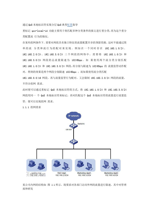
1.1.1 组网需求某公司内网的结构如图1-1所示,现要求对各部门访问外网的流量进行限速。
其中对管理部和研发部分别限速1024Kbps,市场部(包含两个子部门)的总流量限速为2048Kbps。
1.1.2 配置思路z 对管理部和研发部的流量进行限速比较简单,可以通过两个流分类分别匹配两个部门的网段,然后与相应的限速动作进行配对。
z 而对于市场部的限速则需要通过QoS 本地标识符来实现,首先将市场部两个子部门的流量使用QoS 本地标识符来标记,然后再将匹配该标识符的流分类与限速动作进行配对,才能将两个子部门的流量共同限定在一个速率之内。
1.1.3 适用产品、版本表1-1 配置适用的产品与软件版本关系产品软件版本S7500E 系列以太网交换机Release 6100 系列,Release 6300 系列,Release 6600 系列,Release 6610 系列S7600 系列以太网交换机Release 6600 系列,Release 6610 系列S5800&S5820X 系列以太网交换机Release 1110,Release 1211CE3000-32F 以太网交换机Release 12111.1.4 配置过程和解释z 对管理部和研发部上行流量的限制# 创建基本IPv4 ACL 2001,匹配管理部发送的流量。
hcnabigdata-单选题

1.Spark是用以下那种编程语言实现的?A.CB.C++C.JAVAD.Scala2.FusionInsight Manager对服务的管理操作,下面说法错误的是?A.可对服务进行启停重启操作B.可以添加和卸载服务C.可以设置不常用的服务隐藏或显示D.可以查看服务的当前状态4. FusionInsight HD的Loader在创建作业时,Connector有什么作用?A.确定有哪些转换步骤B.提供优化参数,提高数据导入/导出性能C.配置作业如何与外部数据进行连接D.配置作业如何与内部数据进行连接B.hdfs fsck /-deleteC.hdfs dfsadmin -reportD.hdfs balancer - threshold 16. YARN中设置队列QueueA的最大使用资源量,需要配置哪个参数?A.yarn_scheduler.capacity.root. er-limit-factorB.yarn_scheduler.capacity.root. QueueA.minimum-user-limit-factorC.yarn_scheduler.capacity.root. QueueA.stateD.yarn_scheduler.capacity.root. QueueA.maximum- capacity7. FusionInsight Manager对服务的配置功能说法不正确的是A、服务级别的配置可对所有实例生效B、实例级别的配置只针对本实例生效C、实例级别的配置对其他实例也生效D、配置保存后需要重启服务才能生效8.关于fusioninsight HD安装流程,说法正确的是:A安装manager〉执行precheck>执行preinstall>LLD工具配置〉安装集群〉安装后检查〉安装后配置B LLD工具配置〉执行preinstall〉执行precheck〉安装manager〉安装集群〉安装后检查〉安装后配置C安装manager> LLD工具配置〉执行precheck〉执行preinstall〉安装集群〉安装后检查〉安装后配置D LLD工具配置〉执行preinstall〉执行precheck〉安装集群〉安装manager〉安装后检查〉安装后配置9.关于Kerberos部署,描述正确的是?A.Kerberos仅有一个角色B.Kerberos服务在同一个节点上有两个实例C.Kerberos服务采用主备模式部署D.Kerberos服务必须和LDAP服务部署在同一个节点10.某银行规划fusioninsight HD集群有90个节点,如果控制节点规划了3个,那集群中数据节点推荐规划多少最为合理?B.85C.90D.8618.用户集群有150个节点,每个节点12块磁盘(不做RAID,不包括OS盘),每块磁盘大小1T,只安装HDFS,根据建议,最大可存储多少数据?A、1764TBB、1800TBC、600TBD、588TB20.FusionInsight HD节点不支持那种主机操作系统?A、Suse 11.1B、RedHat 6.5C、CentOS 6.4D、Ubuntu 11.0421.HBase shell命令中,哪个可以查看当前登陆的用户和权限组?C.whoD.get_user23. Fusionsight HD manager界面Hive日志收集,哪个选项不正确?A、可指定实例进行日志收集,比如制定单独收集METASTORE的日志B、可指定时间段进行日志收集,比如只收集2016-1-1到2016-1-10的日志C、可指定节点IP进行日志收集,例如仅下载某个IP的日志D、可指定特定用户进行日志收集,例如仅下载userA用户产生的日志27. FusionInsight HD三层组网适合多少节点的集群规模?A、30节点以下B、100节点以下C、100-200 节点D、200节点以上 30.Hadoop系统中关于客户端向HDFS文件系统上传文件说法正确的是?A. 客户端的文件数据经过NameNode传递给DataNodeDataNode 中C.客户端根据DataNode的地址信息,按顺序将整个文件写入每一个DataNode中,然后由将文件划分为多个BlockD. 客户端只上传数据到一个DataNode,然后由NameNode负责Block复制31. FusionInsight HD 系统中,HBase 的最小处理单元是 region,user region 和region server之间的路由信息是保存在哪?A.ZookeeperB.HDFSC.MasterD.Meta 表34.通过FusionInsight Manager不能完成以下哪个操作?A、安装部署B、性能监控C、权限管理D、虚拟机分配39.关于Hbase的Region分裂流程split的描述不正确的是?A、Split过程中并没有真正的将文件分开,仅仅是创建了引用文件B、Split为了减少region中数据大小,从而将一个region分裂成两个regionC、Split过程中该表会暂停服务D、Split过程中被分裂的region会暂停服务43.关于FusionInsight Manager关键特性,说法正确的是?A.能够针对整个集群,某个服务器进行健康检查,不能够针对节点进行健康检查B.Manager引入角色的概念,采用RBAC的方式对系统进行权限管理C.整个系统使用Kerberos管理用户,使用Ldap进行认证,通过CAS实现单点登录D.对于健康检查结果,不能够导出检查报告,只能够在线查看44.查看kafka某topic的partition详细信息时,使用如下哪个命令?A.bin/kafka-topics.sh - createB.bin/kafka-topics.sh - listC.bin/kafka-topics.sh -describeD.bin/kafka-topics.sh -delete45.FusionInsight Hadoop集群中,在某个节点上通过df-hT查询,看到的分区包含以下几个: /var/log Raid 1/srv/BigData Raid 1/srv/BigData/hadoop/data5 Non-Raid/Raid0/srv/BigData/solr/solrserver3Non-Raid/Raid0/srv/BigData/dbdata_om Raid 1这些分区所对应磁盘最佳Raid级别的规划组合是?A、RaidO、 Raid1、 RaidO、 Non-Raid、 Raid-1B、Raid1、 Raid1、 Non-Raid、 Non-Raid、 Raid1C、RaidO、 RaidO、 RaidO、 RaidOD、Non-Raid、Non-Raid、Non-Raid、Non-Raid、Raid146.FusionInsigh HD 系统中 HDFS 默认 Block Size 是多少?A、32MB、64MC、128MD、256M47.FusionInsigh HD部署时,同一集群内的Flume server节点建议至少部署几个?A、1B、2C、3D、448.FusionInsight HD系统设计日志不可以记录下面那些操作?A、手动清除告警B、启停服务实例C、删除服务实例D、查询历史监控50.Hadoop的HBase不适合哪些数据类型的应用场景?A.大文件应用场景B.海量数据应用场景C.高吞吐率应用场景D.半结构化数据应用场景53.安装FusionInsight HD的Streaming组件时,Nimbus角色要求安装几个节点?A、1B、2C、3D、454.关于FusionInsight HD中Loader作业描述正确的是?A.Loader将作业提交到Yam执行后,如果Loader服务出现异常,则此作业执行失败B.Loader将作业提交到Yame执行后,如果某个Mapper执行失败,能够自动进行重试C.Loader作业执行失败,将会产生垃圾数据,需要用户手动清除D.Loader将作业提交到Yam执行后,在该作业执行完成前,不能再提交其他作业56. Hadoop平台中,要查看YARN服务中一个application的信息,通常需要使用什么命令?A、 containerB、applicationattemptC、jarD、 application57.在FusionInsight集群规划部署时,建议管理节点最好部署()个,控制节点最少部署(),数据节点最少部署()A.1,2,2B.1,3,2C.2,3,1D.2,3,359.FusionInsight HD安装过程中,执行Preinstall操作不能完成哪项功能?A.修改OS,确保OS满足FusionInsight HD的安装要求B.安装 MangerC.格式化分区D.安装OS缺失的RPM包60.SolrCloud模式是集群模式,在此模式下Solr服务强依赖于一下哪个服务?A.HbaseB.HDFSC.ZooKeeperD.Yarn 62. Hadoop的MapReduce组件擅长处理哪些场景的计算任务?A、迭代计算B、离线计算C、实时交互计算D、流式计算67.以下哪些数据不属于半结构化数据?A.HtmlB.XmlC.二维表D. Json68.关于 FusionInsight HD Streaming 客户端的 Supervisor 描述正确的是?A、Supervisor负责资源分配和资源调度B、Supervisor负责接管Nimbus分配的任务,启动和停止属于自己管理的worker进程C、Supervisor是运行具体处理逻辑的进程D、Supervisor是一个Topology中接收数据然后执行处理的组件70.关于 FusionInsight Manager,说法错误的是?A、NTP sever/client负责集群内各节点的时钟同步B、通过FusionInsight Manager,可以对HDFS进行启停控制、配置参数C、FusionInsight Manager所有维护操作只能够通过WebUI来完成,没有提供Shell维护命令D、通过FusionInsight Manager,可以向导式安装集群,缩短集群部署时间74. FusionInsight HD系统中如果修改了服务的配置项,不进行服务重启,该服务的配置状态是什么状态?A、SYNCHRONIZEDB、EXPIREDC、CONFIGURINGD、UNKNOWN80. Spark应用在运行时,Stage划分的依据是哪个?A、taskB、taskSet84.采用Flume传输数据过程中,为了防止因Flume进程重启而丢失数据,推荐使用以下哪种channel类型?A、Memory ChannelB、File ChannelC、JDBC ChannelD、HDFS Channel89. Fusioninsight HD的Hbase中一张表包含以下几个Region[10,20),[20,30),[30,+8),分别编号为①,②,③,那么,11, 20, 222 分别属于哪个 Region?A、①①③B、①②③C、①②②D、①①②90.关于Hive建表基本操作描述正确的是?A.创建外部表时需要指定external关键字B.一旦表创建好,不可再修改表名C.一旦表创建好,不可再修改列名D. 一旦表创建好,不可再增加新列92.Fusioninsight HD系统中,如果Solr索引默认存放在HDFS上,以下理解正确的有?A. 不需要考虑各solrserver实例上创建了多少shardB.为保证数据可靠性,创建索引时必须创建多RelicaC.通过HDFS读取索引时占用磁盘IO,因此不建议Solr实例与DataNode部署在同一节点上D. 当Solr服务参数INDEX_STORED_ON_HDFS值为HDFS时,创建Collection的索引就默认存储在HDFS上。
KIEN301和6M3024M 工业以太网交换机用户手册

第四章 KIEN3024M 硬件结构.................................................................................................................. 17 4.1 系统结构 ......................................................................................................................................... 17 4.2 整机结构 ......................................................................................................................................... 17 4.2.1 机箱 ...................................................................................................................................... 17 4.2.2 前面板 .................................................................................................................................. 18 4.2.3 后面板 .................................................................................................................................. 19
高清网络摄像机用户手册(IPC410412)
目录/ Contents目录/ CONTENTS (1)前言 (3)读者对象 (3)说明 (3)安全说明 (4)产品简介 (5)安装设备 (6)安装环境 (6)准备线缆 (6)设备安装与连线 (7)开始使用 (15)客户端PC机配置要求 (15)初始配置 (15)使用客户端IPCCtrl (17)产品功能 (18)视频浏览 (18)云台控制 (18)图像调节 (18)告警联动 (20)图像遮蔽 (21)抓拍管理 (22)录像管理 (22)升级管理 (23)附录 (24)FAQ (24)性能指标 (31)术语表 (32)P REFACE (1)T ARGET R EADERS (1)M ODELS (1)R ELATED M ANUALS (1)C AUTION (2)Main features (3)Installation (4)General Environment (4)Connection Cable (4)Mount the device (5)U SING IPC410 (13)System Requirement (13)Initially Configuration (13)Using the Client - IPCCtrl (15)P RODUCT F EATURE (16)Live Video (16)PTZ Control (16)Adjusting the camera and image (16)Alarm Trigger (20)Image Shield (21)S NAPSHOT M ANAGEMENT (21)R ECORD M ANAGEMENT (22)U PDATE (23)A PPENDIX (24)Troubleshooting (24)Specifications (29)G LOSSARY (30)前言前言读者对象工程安装人员监控产品操作人员说明适用型号:IPC410/ IPC412 高清高速球型摄像机相关手册:《NVR管理员指南》本手册详细介绍了IPC410/412的功能、安装和使用操作等方法。
clearpass配置实验
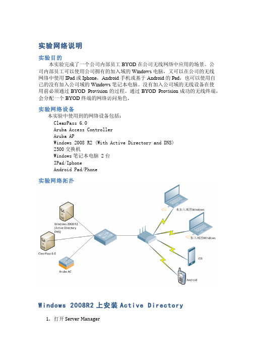
实验网络说明实验目的本实验完成了一个公司内部员工BYOD在公司无线网络中应用的场景。
公司内部员工可以使用公司拥有的加入域的Windows电脑,又可以在公司的无线网络中使用IPad或Iphone,Android手机或基于Android的Pad,也可以使用自己的没有加入公司域的Windows笔记本电脑。
没有加入公司域的无线设备在使用前必须通过BYOD Provision的过程。
通过BYOD Provision成功的无线终端,会分配一个BYOD终端的网络访问角色。
实验网络设备本实验中使用到的网络设备包括:ClearPass 6.0Aruba Access ControllerAruba APWindows 2008 R2 (With Active Directory and DNS)2500交换机Windows笔记本电脑 2台IPad/IphoneAndroid Pad/Phone实验网络拓扑Windows 2008R2上安装Active Directory1.打开 S erver M anager2.点击“Roles”,点击“Add Roles”,出现下面的界面3.点击“Next”进入下面的界面4.选择“Active Directory Domain Services”,系统提示安装.NET FrameworkFeatures,直接点击“Add Required Features”进入安装5.系统出现下面的提示后,直接点击“Next”6.在下面的界面中直接点击“Install”7.安装完成后,出现下面的界面Windows 2008R2上安装DNS ServerDNS S ever的安装方法和Active D irectory一样,下面是安装DNS配置完成后的界面。
只要能保证DNS能够解析出Active Directory服务器的地址即可。
这里是10.64.7.11ClearPass中配置证书(如果不想使用自己的证书,此步骤可以省略)1.点击“Dashboard”>>“ClearPass Guest”,进入ClearPass Guest配置页面2.导航到“Onboard”>>“Certificate Authority Setting”证书管理页面3.输入下图中的必要项,点击“Create Root Certificate”来产生一个证书4.回到“ClearPass Policy Manager”,导航到“Administration”>>“Certificates”>>“Server Certificate”,点击“Create Self-Signed Certificate”来创建一个新的服务器证书。
IBM Cognos Transformer V11.0 用户指南说明书
H3C交换机QOS限速案例

企业网用户的IP为10.0.0.2/24,通过Switch连接Internet。
Switch为运营商设备。
企业网用户只租用了1Mbps的上行带宽和2Mbps的下行带宽。
普通CAR配置组网图一、配置思路流量监管功能是通过QoS命令行实现。
本案例中,用户采用固定IP,因此可以通过匹配用户IP地址的方法匹配用户流量,并对其做流量监管。
二、配置步骤# 配置ACL规则匹配源IP为10.0.0.2的流量。
<H3C> system-view[H3C] acl number 3001[H3C-acl-adv-3001] rule permit ip source 10.0.0.2 0[H3C-acl-adv-3001] quit# 配置ACL规则匹配目的IP为10.0.0.2的流量。
[H3C] acl number 3002[H3C-acl-adv-3002] rule permit ip destination 10.0.0.2 0[H3C-acl-adv-3002] quit# 配置流分类,匹配ACL规则3001,即匹配源IP为10.0.0.2的流量。
[H3C] traffic classifier source_hostA[H3C-classifier-source_hostA] if-match acl 3001[H3C-classifier-source_hostA] quit# 配置流分类,匹配ACL规则3002,即匹配目的IP为10.0.0.2的流量。
[H3C] traffic classifier destination_hostA[H3C-classifier-destination_hostA] if-match acl 3002[H3C-classifier-destination_hostA] quit# 配置流行为,用于对上行流量进行流量监管,速率为1000kbps。
[H3C] traffic behavior uplink[H3C-behavior-uplink] car cir 1000[H3C-behavior-uplink] quit吉林省金铖计算机学校# 配置流行为,用于对下行流量进行流量监管,速率为2000kbps。
交换机命令配置手册 北京博维

工业以太网交换机 命令行配置手册
1
目
第1章 1.1 1.2 1.2.1 1.2.2 1.2.3 1.2.4 第2章 2.1 2.1.1 2.1.2 2.1.3 2.2 2.3 2.3.1 2.3.2 2.3.3 2.4 2.4.1 2.4.2 2.4.3 2.4.4 第3章 3.1 3.2 3.2.1 3.2.2 3.2.3 3.2.4 3.2.5 第4章 4.1 4.1.1 4.1.2 4.1.3 4.2 4.2.1 4.2.2
系统软件管理...................................................................................................................... 4 配置文件管理...................................................................................................................... 4 典型配置举例...................................................................................................................... 4
QOS详解

NetApp磁盘阵列安装手册
NetApp磁盘阵列安装手册目录目录 (1)一、磁盘阵列的系统安装 (2)1.1初始化磁盘阵列 (2)1.2输入license序列号 (8)1.3配置CIFS (9)1.4在机头中安装阵列操作系统 (11)二、磁盘阵列的SSL安全认证配置 (13)2.1通过浏览器来管理磁盘阵列 (13)2.2配置SSL安全认证 (15)三、磁盘阵列的空间配置和分配 (18)3.1在aggr0中添加新的磁盘 (18)3.2消除磁盘Aggregate的快照预留空间 (22)3.3缩小卷vol0的磁盘空间 (22)3.4创建新的Volume (27)3.5消除Volume的快照预留空间 (31)3.6在新建卷上的参数修改 (33)3.7在IBM主机上安装NetApp磁盘路径管理软件 (34)3.8创建LUN存储单元 (36)3.8.1开启FCP功能 (36)3.8.2创建一个Qtree (38)3.8.3创建一个Lun存储单元 (39)3.8.4在主机上使用LUN来存储数据 (44)一、磁盘阵列的系统安装1.1初始化磁盘阵列NetApp FAS3020C是NetApp产品中一款有双机头的磁盘阵列,需要先在每个机头中安装好操作系统,才能正常使用。
安装步骤如下:1,通过笔记本电脑或其它Windows平台PC机的串口,连接到机头上的串口上;2,通过超级终端,以默认值连接来进行操作;操作过程如下:CFE version 3.0.0 based on Broadcom CFE: 1.0.40Copyright (C) 2000,2001,2002,2003 Broadcom Corporation.Portions Copyright (c) 2002-2005 Network Appliance, Inc.CPU type 0xF29: 2800MHzTotal memory: 0x80000000 bytes (2048MB)CFE> bye输入bye 后,开始启动;CFE version 3.0.0 based on Broadcom CFE: 1.0.40Copyright (C) 2000,2001,2002,2003 Broadcom Corporation.Portions Copyright (c) 2002-2005 Network Appliance, Inc.CPU type 0xF29: 2800MHzTotal memory: 0x80000000 bytes (2048MB)Starting AUTOBOOT press any key to abort...Loading: 0x200000/24732624 0x19963d0/33360796 0x3966f70/1995456 Entry at 0x00200000 Starting program at 0x00200000Press CTRL-C for special boot menu提示按CTRL-C后弹出启动菜单;Special boot options menu will be available.Mon Mar 20 07:54:25 GMT [cf.nm.nicTransitionUp:info]: Interconnect link 0 is UPNetApp Release 7.0.3: Fri Dec 2 06:00:21 PST 2005Copyright (c) 1992-2005 Network Appliance, Inc.Starting boot on Mon Mar 20 07:54:14 GMT 2006(1) Normal boot.(2) Boot without /etc/rc.(3) Change password.(4) Initialize all disks.(4a) Same as option 4, but create a flexible root volume.(5) Maintenance mode boot.Selection (1-5)?4a这里选择4a,初始化所有的磁盘,并且创建一个root卷,此卷将用于操作系统的安装;Zero disks and install a new file system? y选择y,确认将所有的磁盘零化,并且安装新的文件系统;This will erase all the data on the disks, are you sure? Y选择y,确认将删除磁盘上的所有数据;Zeroing disks takes about 80 minutes. .................................................................................................................................................................... .................................................................................................................................................................... .................................................................................................................................................................... .................................................................................................................................................................... .................................................................................................................................................................... .................................................................................................................................................................... .................................................................................................................................................................... ..................................................................Mon Mar 20 09:15:30 GMT [raid.disk.zero.done:notice]: Disk 0a.23 Shelf ? Bay ? [NETAPP X276_S10K7288F10 NA01] S/N [3KR16HQC00007617E7VE] : disk zeroing complete...............Mon Mar 20 09:15:34 GMT [raid.disk.zero.done:notice]: Disk 0a.18 Shelf ? Bay ? [NETAPP X276_S10K7288F10 NA01] S/N [3KR18YGC000076187JGK] : disk zeroing complete ....................Mon Mar 20 09:15:40 GMT [raid.disk.zero.done:notice]: Disk 0a.20 Shelf ? Bay ? [NETAPP X276_S10K7288F10 NA01] S/N [3KR18MYR0000761769S1] : disk zeroing complete .............Mon Mar 20 09:15:43 GMT [raid.disk.zero.done:notice]: Disk 0a.22 Shelf ? Bay ? [NETAPP X276_S10K7288F10 NA01] S/N [3KR18QV900007617LZY3] : disk zeroing complete ..................Mon Mar 20 09:15:48 GMT [raid.disk.zero.done:notice]: Disk 0a.16 Shelf ? Bay ? [NETAPP X276_S10K7288F10 NA01] S/N [3KR18PE1000076187KXZ] : disk zeroing complete ...............Mon Mar 20 09:15:52 GMT [raid.disk.zero.done:notice]: Disk 0a.21 Shelf ? Bay ? [NETAPP X276_S10K7288F10 NA01] S/N [3KR17PT300007617M1P2] : disk zeroing complete .................................................................................................................................................................... ...............Mon Mar 20 09:16:42 GMT [raid.disk.zero.done:notice]: Disk 0a.17 Shelf ? Bay ? [NETAPP X276_S10K7288F10 NA01] S/N [3KR18Y6700007617695Y] : disk zeroing complete .................................................................................................................................................................... .............Mon Mar 20 09:18:44 GMT [raid.disk.zero.done:notice]: Disk 0a.19 Shelf ? Bay ? [NETAPP X276_S10K7288F10 NA01] S/N [3KR1911Z0000761769R8] : disk zeroing completeMon Mar 20 09:18:45 GMT [raid.vol.disk.add.done:notice]: Addition of Disk /aggr0/plex0/rg0/0a.18 Shelf 1 Bay 2 [NETAPP X276_S10K7288F10 NA01] S/N [3KR18YGC000076187JGK] to aggregate aggr0 has completed successfullyMon Mar 20 09:18:45 GMT [raid.vol.disk.add.done:notice]: Addition of Disk /aggr0/plex0/rg0/0a.17 Shelf 1 Bay 1 [NETAPP X276_S10K7288F10 NA01] S/N [3KR18Y6700007617695Y] to aggregate aggr0 has completed successfullyMon Mar 20 09:18:45 GMT [raid.vol.disk.add.done:notice]: Addition of Disk /aggr0/plex0/rg0/0a.16 Shelf 1 Bay 0 [NETAPP X276_S10K7288F10 NA01] S/N [3KR18PE1000076187KXZ] to aggregate aggr0 has completed successfullyMon Mar 20 09:18:45 GMT [wafl.vol.add:notice]: Aggregate aggr0 has been added to the system. Mon Mar 20 09:18:46 GMT [fmmbx_instanceWorke:info]: no mailbox instance on primary sideMon Mar 20 09:18:47 GMT [fmmbx_instanceWorke:info]: Disk 0a.18 is a primary mailbox disk Mon Mar 20 09:18:47 GMT [fmmbx_instanceWorke:info]: Disk 0a.17 is a primary mailbox disk Mon Mar 20 09:18:47 GMT [fmmbx_instanceWorke:info]: normal mailbox instance on primary side Mon Mar 20 09:18:47 GMT [fmmbx_instanceWorke:info]: Disk 0b.18 is a backup mailbox diskMon Mar 20 09:18:47 GMT [fmmbx_instanceWorke:info]: Disk 0b.17 is a backup mailbox diskMon Mar 20 09:18:47 GMT [fmmbx_instanceWorke:info]: normal mailbox instance on backup sideMon Mar 20 09:18:48 GMT [lun.metafile.dirCreateFailed:error]: Couldn't create vdisk metafile directory /vol/vol0/vdisk.DBG: Set filer.serialnum to: 1071155ifconfig e0a mediatype autoConfiguring onboard ethernet e0a.Contacting DHCP server.Ctrl-C to skip DHCP search ...Mon Mar 20 09:18:48 GMT [rc:info]: Contacting DHCP serverMon Mar 20 09:18:52 GMT [rc:info]: DHCP config failedConfiguring e0a using DHCP failed.NetApp Release 7.0.3: Fri Dec 2 06:00:21 PST 2005System ID: 010******* (); partner ID: <unknown> ()System Serial Number: 1071155 ()System Rev: E0slot 0: System BoardProcessors: 1Memory Size: 2048 MBslot 0: Dual 10/100/1000 Ethernet Controller VIe0a MAC Address: 00:a0:98:03:88:13 (auto-unknown-cfg_down)e0c MAC Address: 00:a0:98:03:88:10 (auto-unknown-cfg_down)e0d MAC Address: 00:a0:98:03:88:11 (auto-unknown-cfg_down) slot 0: FC Host Adapter 0a8 Disks: 2176.0GB1 shelf with ESH2slot 0: FC Host Adapter 0b8 Disks: 2176.0GB1 shelf with ESH2slot 0: Fibre Channel Target Host Adapter 0cslot 0: Fibre Channel Target Host Adapter 0dslot 0: SCSI Host Adapter 0eslot 0: NetApp ATA/IDE Adapter 0f (0x000001f0)0f.0 245MBslot 3: NVRAMMemory Size: 512 MBPlease enter the new hostname []: headb输入这个机头的主机名,这里举例为headb;Do you want to configure virtual network interfaces? [n]: y问是否要配置虚拟网卡,如果要创建的话,输入y;Number of virtual interfaces to configure? [0] 1输入要配置几块虚拟网卡,如配置1块虚拟网卡,就输入1;Name of virtual interface #1 []: vif1输入虚拟网卡的名称,这里举例为vif1;Is vif1 a single [s] or multi [m] virtual interface? [m] s选择虚拟网卡的类型是single还是multi,这里选择s;Number of links for vif1? [0] 2虚拟网卡所包含真实网卡的数量,如果用两块网卡绑定成一块虚拟网卡就输入2;Name of link #1 for vif1 []: e0a输入用于绑定的真实网卡的设备名,可以从阵列设备后面的网络接口上看到;Name of link #2 for vif1 []: e0b输入用于绑定的真实网卡的设备名,可以从阵列设备后面的网络接口上看到;Please enter the IP address for Network Interface vif1 []: 192.168.0.88输入虚拟网卡的IP地址;Please enter the netmask for Network Interface vif1 [255.255.255.0]:输入虚拟网卡的掩码,默认就直接回车;Should virtual interface vif1 take over a partner virtual interface during failover? [n]: y是否允许虚拟网卡在故障时切换到另一个机头上,输入y;The clustered failover software is not yet licensed. To enablenetwork failover, you should run the 'license' command forclustered failover.会提示说没有输入Clustered failover功能的license,需要输入才能实现网络切换功能;Please enter the partner virtual interface name to be taken over by vif1 []: vif1输入另一个机头上的会被切换过来的虚拟网卡的名字;Please enter media type for vif1 {100tx-fd, tp-fd, 100tx, tp, auto (10/100/1000)} [auto]:输入虚拟网卡的类型,一般是自适应,选默认auto;Please enter the IP address for Network Interface e0c []:输入网卡e0c的IP地址,不设置就直接回车;Should interface e0c take over a partner IP address during failover? [n]: n是否允许网卡e0c在故障时切换到另一个机头上,这里不配置就输入n;Please enter the IP address for Network Interface e0d []:输入网卡e0d的IP地址,不设置就直接回车;Should interface e0d take over a partner IP address during failover? [n]: n是否允许网卡e0d在故障时切换到另一个机头上,这里不配置就输入n;Would you like to continue setup through the web interface? [n]: n问是否通过web方式来进行继续的安装,输入n,不需要;Please enter the name or IP address of the default gateway:输入默认网关的名字和IP地址,无须输入就直接回车;The administration host is given root access to the filer's/etc files for system administration. To allow /etc root accessto all NFS clients enter RETURN below.Please enter the name or IP address of the administration host:输入超级管理主机的主机名或IP地址,没有就直接回车;Where is the filer located? []: nanjing问磁盘阵列设备的位置,可以随便写,比如南京,就输入nanjing;Do you want to run DNS resolver? [n]:是否配置DNS,输入n,不配置;Do you want to run NIS client? [n]:是否配置NIS,输入n,不配置;This system will send event messages and weekly reports to Network Appliance Technical Support. To disable this feature, enter "options autosupport.support.enable off" within 24 hours. Enabling Autosupport can significantly speed problem determination and resolution should a problem occur on your system. For further information on Autosupport, please see: /autosupport/ Press the return key to continue.提示说,阵列系统默认的自动发送事件日志和周报告功能是打开的,如果需要关闭,请输入options autosupport.support.enable off。
终端服务器的原理和安装激活过程

终端服务终端服务基本由三部分技术组成,即客户端部分、协议部分及服务器端部分。
客户端和服务器通过我们的远程桌面协议进行通讯。
客户端是轻量级的软件,负责解释来自终端服务的信息,并以远程终端服务桌面位图或视图的方式显示这些信息。
终端服务的工作方式为,可能与终端服务相距很远的客户端用户可以像坐在终端服务器前一样地执行操作和使用远程终端服务。
客户端把键盘输入、鼠标移动和鼠标点击信息发送给终端服务。
终端服务得到这些信息,在终端服务的会话内完成所需的操作,然后将更新后的信息发送回客户端。
Microsoft ClearinghouseMicrosoft Clearinghouse 是Microsoft 维护的数据库,用以激活终端服务器许可证服务器,并在申请客户端许可证密钥包的终端服务器许可证服务器上安装它们。
Clearinghouse 存储有关所有激活的终端服务器许可证服务器以及已颁发的密钥包的信息。
这可以帮助跟踪组织内客户端使用终端服务器的情况,以确保购买了足够数量的客户端许可证。
Microsoft Clearinghouse 可以从终端服务器许可证服务器激活向导进行访问。
许可证服务器终端服务器授权服务器存储所有客户端许可证,这些许可证已经安装用于终端服务器。
在可以向客户端颁发许可证之前,终端服务器必须能够连接到激活的终端服务器许可证服务器。
一台终端服务器许可证服务器可同时为多台终端服务器服务。
在安装终端服务器许可证服务器之前,应考虑需要以下两种类型的许可证服务器中的哪一种:域许可证服务器或企业许可证服务器。
在终端服务器授权安装过程中,选择系统所需的许可证服务器类型,即域许可证服务器还是企业许可证服务器。
在默认情况下,许可证服务器安装为企业许可证服务器。
域许可证服务器也可以选择将许可证服务器安装为域许可证服务器。
如果要为每个域维护单独的许可证服务器,则该类型的许可证服务器会比较适合。
请记住,仅当终端服务器与许可证服务器处于同一域中时,终端服务器才可以访问域许可证服务器。
HPE ProLiant Gen10 服务器的故障排除指南
© Copyright 2017-2019 Hewlett Packard Enterprise Development LP通知本文档中包含的信息如有更改,恕不另行通知。
随 Hewlett Packard Enterprise 产品和服务提供的明确保修声明中阐明了此类产品和服务的全部保修服务。
此处的任何内容都不应视作额外的担保信息。
对于本文档中包含的技术或编辑方面的错误或疏漏,Hewlett Packard Enterprise 不承担任何责任。
保密的计算机软件。
必须具有 Hewlett Packard Enterprise 颁发的有效许可证,方可拥有、使用或复制本软件。
按照 FAR 12.211 和 12.212 的规定,可以根据供应商的标准商业许可证授权美国政府使用商用计算机软件、计算机软件文档以及商业编号的技术数据。
单击指向第三方网站的链接将会离开 Hewlett Packard Enterprise 网站。
Hewlett Packard Enterprise 无法控制 Hewlett Packard Enterprise 网站之外的信息,也不对这些信息承担任何责任。
商标声明Microsoft®、Windows®和 Windows Server®是 Microsoft Corporation 在美国和(或)其他国家(或地区)的注册商标或商标。
Linux®是 Linus Torvalds 在美国和其他国家(地区)的注册商标。
Red Hat®是 Red Hat, Inc. 在美国及其他国家(地区)的注册商标。
SD 和 microSD 是 SD-3C 在美国和/或其他国家(地区)的商标或注册商标。
VMware®是 VMware, Inc. 在美国和/或其他司法辖区的注册商标或商标。
目录使用本指南 (10)入门 (10)支持的服务器 (10)其它故障排除资源 (11)故障排除的准备工作 (12)服务器故障排除的前提条件 (12)重要安全信息 (12)设备上的符号 (13)警告和小心 (13)静电释放 (14)防止静电释放 (14)防止静电释放的接地方法 (15)收集症状信息 (15)诊断服务器前的准备工作 (15)处理器故障排除准则 (16)将服务器降级到最低硬件配置 (17)常见问题的解决方法 (18)解决连接松动问题 (18)搜索服务通知 (18)固件更新 (18)在启用了 HPE 可信平台模块和 BitLocker 的情况下更新服务器 (19)DIMM 处理准则 (19)DIMM 和 NVDIMM 安装信息 (19)在 HPE ProLiant Gen10 服务器上支持的 Intel Xeon 可扩展处理器 (20)DIMM-处理器兼容性 (20)NVDIMM-处理器兼容性 (20)组件 LED 指示灯定义 (20)存储 (20)SAS、SATA 和 SSD 驱动器准则 (20)热插拔驱动器 LED 定义 (21)半高 LFF 驱动器 LED 指示灯定义 (22)NVMe SSD LED 指示灯定义 (22)SFF 闪存适配器组件和 LED 指示灯定义 (24)系统电源 LED 指示灯定义 (24)运行状态条形 LED 指示灯定义(仅限 c 系列服务器刀片) (25)前面板 LED 指示灯和按钮 (25)前面板 LED 指示灯注释 (26)使用服务器运行状况摘要 (26)前面板 LED 指示灯电源故障代码 (28)控制器和能源包电缆 (29)远程故障排除 (30)远程故障排除工具 (30)远程访问 Virtual Connect Manager (31)3使用 iLO 远程排除服务器和服务器刀片的故障 (31)使用 Onboard Administrator 对服务器刀片进行远程故障排除 (32)使用 OA CLI (32)诊断流程图 (34)诊断步骤 (34)在开始之前收集重要信息 (34)故障排除流程图 (34)使用诊断流程图 (34)初始诊断 (34)远程诊断流程图 (35)开机故障流程图 (36)ML 和 DL 系列服务器的服务器开机故障流程图 (36)XL 系列服务器的服务器开机故障流程图 (38)BL 系列服务器刀片的服务器刀片开机故障流程图 (40)POST 故障流程图 (43)POST 问题 - 服务器在 POST 期间挂起或重新引导流程图 (44)POST 问题 - 无法引导,没有视频流程图 (46)POST 问题 - 可以引导,没有视频流程图 (47)操作系统引导故障流程图 (48)Intelligent Provisioning 故障流程图 (49)控制器故障流程图 (51)HPE Smart Array 控制器的能源包问题 (53)物理驱动器故障流程图 (56)逻辑驱动器故障流程图 (58)故障指示流程图 (59)非刀片服务器的服务器故障指示流程图 (60)BL c 系列服务器刀片的服务器刀片故障指示流程图 (62)网卡故障流程图 (64)常规诊断流程图 (67)硬件问题 (70)用于所有 ProLiant 服务器的步骤 (70)电源问题 (70)服务器无法开机 (70)供电来源问题 (70)电源问题 (71)没有足够的电源配置 (72)UPS 问题 (73)UPS 无法正常供电 (73)显示电池电量不足警告 (74)UPS 上的一个或多个 LED 指示灯呈红色 (74)常规硬件问题 (74)新硬件问题 (74)未知问题 (76)第三方设备问题 (76)测试设备 (77)驱动器问题(硬盘驱动器和固态驱动器) (78)驱动器发生故障 (78)无法识别驱动器 (78)无法访问数据 (79)服务器响应时间比平时长 (80)HPE SmartDrive 图标或 LED 指示灯指示驱动器错误,或者在 POST、HPE SSA 或HPE SSADUCLI 中显示错误消息 (81)4SSD Smart Wear 错误 (81)诊断阵列问题 (81)HPE Smart Array SR 和 MR Gen10 控制器的诊断工具 (81)存储控制器问题 (82)常规控制器问题 (82)控制器不再是冗余的 (83)在 RAID 模式下访问的驱动器上的数据与在非 RAID 模式下访问的数据不兼容 (84)在将驱动器移到新的服务器或 JBOD 后,Smart Array 控制器不显示这些驱动器 (84)驱动器漫游 (84)具有 10 SFF 驱动器背板或 12 LFF 驱动器背板的服务器上的数据故障或磁盘错误 (84)禁用 RAID 模式后找不到 HPE Smart Array S100i SR Gen10 驱动器 (85)无法识别 HPE Smart Array S100i SR Gen10 驱动器 (85)风扇和散热问题 (86)常规风扇问题 (86)风扇的运行速度比预期速度高 (87)风扇噪音太大(高速) (87)风扇噪音太大(低速) (88)热插拔风扇问题 (88)HPE BladeSystem c 系列机箱风扇高速运行 (89)内存问题 (89)常规内存问题 (89)隔离并最小化内存配置 (90)服务器内存不足 (90)DIMM 配置错误 (90)服务器无法识别现有的内存 (91)服务器无法识别新的内存 (92)无法修复的内存错误 (93)超过可纠正的内存错误阈值 (94)NVDIMM 问题 (94)NVDIMM 安装错误 (94)已禁用 NVDIMM (95)在操作系统中不显示持久性内存驱动器 (96)持久性内存驱动器是只读的 (96)持久性内存驱动器不再具有持久性 (97)HPE 可扩展持久性内存问题 (98)在操作系统中不显示持久性内存驱动器 (98)持久性内存驱动器是只读的 (100)持久性内存驱动器不再具有持久性 (101)HPE 可扩展持久性内存备份和恢复失败 (102)无法配置可扩展持久性内存 (103)处理器问题 (104)排除处理器故障 (104)无法纠正的计算机检查异常 (105)可信平台模块问题 (105)TPM 发生故障或检测不到它 (105)系统电池电量不足或耗尽 (106)主板和电源背板问题 (106)microSD 卡问题 (107)系统无法从 microSD 卡引导 (107)U 盘问题 (107)系统无法从 U 盘引导 (107)图形和视频适配器问题 (108)排除常规图形和视频适配器故障 (108)视频问题 (108)打开服务器电源后屏幕黑屏超过 60 秒 (108)如果使用节能功能,显示器无法正常工作 (109)显示颜色不对 (110)5显示慢慢移动的水平线 (110)鼠标和键盘问题 (110)扩展卡问题 (111)系统在更换扩展卡期间要求使用恢复方法 (111)网络控制器或 FlexibleLOM 问题 (111)安装了网络控制器或 FlexibleLOM,但无法正常工作 (111)网络控制器或 FlexibleLOM 已停止工作 (112)在添加扩展卡后,网络控制器或 FlexibleLOM 停止工作 (112)网络互连模块刀片问题 (113)具有 AMD 处理器的 HPE ProLiant Gen10 服务器的网络性能或虚拟机性能问题 (113)能源包问题 (114)Gen10 服务器中的能源包支持 (114)能源包在长期搁置后可能会耗尽电量 (114)能源包配置错误 (115)能源包故障 (115)电缆问题 (116)在使用较旧的小型 SAS 电缆时,发生驱动器错误、重试、超时和无根据的驱动器故障 (116)无法识别 USB 设备,显示错误消息,或者设备在连接到 SUV 电缆时无法开机 (116)软件问题 (117)操作系统问题和解决方法 (117)操作系统问题 (117)操作系统锁定 (117)错误日志中显示错误 (117)在安装 Service Pack 后出现问题 (117)更新操作系统 (118)更新操作系统的前提条件 (118)更新操作系统 (118)重新配置或重新加载软件 (118)重新配置或重新加载软件的前提条件 (118)还原备份版本 (119)Linux 资源 (119)应用程序软件问题 (119)软件锁定 (119)更改软件设置后出错 (119)更改系统软件后出错 (120)安装了应用程序后出错 (120)ROM 问题 (120)远程 ROM 刷新问题 (120)命令行语法错误 (120)目标计算机上拒绝访问 (121)无效或不正确的命令行参数 (121)网络连接在进行远程通信时失败 (121)ROM 刷新期间发生故障 (121)不支持目标系统 (122)系统在固件更新期间要求使用恢复方法 (122)引导问题 (123)服务器无法引导 (123)UEFI 服务器的 PXE 引导准则 (125)软件和配置实用程序 (126)服务器模式 (126)产品规格说明简介 (126)6Active Health System Viewer (126)Active Health System (127)Active Health System 数据收集 (127)Active Health System 日志 (127)HPE iLO 5 iLO (127)iLO 联合 (128)iLO服务端口 (128)iLO RESTful API (129)RESTful Interface Tool (129)iLO Amplifier Pack (129)Integrated Management Log (129)Intelligent Provisioning (129)Intelligent Provisioning 操作 (130)管理安全性 (131)适用于 Windows 和 Linux 的 Scripting Toolkit (131)UEFI System Utilities (131)选择引导模式 (131)安全引导 (132)启动嵌入式 UEFI Shell (133)HPE Smart Storage Administrator (133)HPE MR Storage Administrator (134)StorCLI (134)USB 支持 (134)外置 USB 功能 (134)支持冗余 ROM (134)安全性和安全优势 (135)使系统保持最新状态 (135)更新固件或系统 ROM (135)Service Pack for ProLiant (135)更新 System Utilities 中的固件 (136)从 UEFI 嵌入式 Shell 中更新固件 (137)联机刷新组件 (137)驱动程序 (137)软件和固件 (137)支持的操作系统版本 (138)HPE Pointnext 产品 (138)主动通知 (138)报告和日志 (139)报告和日志概述 (139)Active Health System 日志 (139)Active Health System 日志下载方法 (139)下载某个日期范围的 Active Health System 日志 (139)下载整个 Active Health System 日志 (140)使用 cURL 下载 Active Health System 日志 (141)清除 Active Health System 日志 (143)通过 IP 下载 AHS 日志 (143)下载 Active Health System 日志 (iLOREST) (144)使用 AHSV 排除故障或打开支持案例 (145)Intelligent Provisioning 诊断工具 (145)Integrated Management Log (145)查看 IML (145)使用 HPE SSA 执行诊断任务 (146)HPE Smart Storage Administrator Diagnostics Utility CLI (146)安装实用程序 (146)7在 CLI 模式下启动该实用程序 (146)诊断报告过程 (147)查看诊断报告 (147)识别和查看诊断报告文件 (147)SmartSSD Wear Gauge 报告过程 (148)查看 SmartSSD Wear Gauge 报告 (148)识别和查看 SmartSSD Wear Gauge 报告文件 (148)HPS 报告 (148)Linux 报告 (148)故障排除资源 (149)在线资源 (149)Hewlett Packard Enterprise 支持中心网站 (149)Hewlett Packard Enterprise 信息库 (149)以前的 HPE ProLiant 服务器型号的故障排除资源 (149)服务器刀片机箱故障排除资源 (149)故障排除资源 (149)服务器文档 (150)服务器用户指南 (150)服务器维护和维修指南 (150)设置和安装指南 (151)HPE iLO 软件文档 (151)UEFI System Utilities 文档 (151)Intelligent Provisioning 软件文档 (151)产品规格说明简介 (151)白皮书 (151)服务通知、咨询和通告 (151)订阅服务 (152)HPE Pointnext 产品 (152)产品信息资源 (152)其他产品信息 (152)HPE SmartMemory 速度信息 (152)注册服务器 (152)服务器功能概述和安装说明 (152)主要功能和选件部件号 (152)服务器和选件的规格、符号、安装警告和通告 (153)HPE Smart Array 控制器文档 (153)备件号 (153)拆卸步骤、部件号和规格 (153)拆卸和更换步骤视频 (153)技术主题 (153)产品安装资源 (153)外部布线信息 (153)电源容量 (154)开关设置、LED 指示灯功能、驱动器、内存、扩展卡和处理器安装说明以及板卡布局.154产品配置资源 (154)Data Center Infrastructure Advisor (154)设备驱动程序信息 (154)DDR4 内存配置 (154)操作系统安装和配置信息(对于出厂时安装的操作系统) (154)服务器配置信息 (154)服务器设置软件的安装和配置信息 (154)服务器的软件安装和配置 (154)HPE iLO 信息 (155)服务器管理 (155)8服务器管理系统的安装和配置信息 (155)容错、安全保护、保养和维护、配置和设置 (155)网站 (156)支持信息和其他资源 (157)获取 Hewlett Packard Enterprise 支持 (157)获取更新 (157)客户自行维修 (158)远程支持 (158)保修信息 (158)法规信息 (158)文档反馈 (159)症状信息检查清单 (160)9使用本指南入门注意:对于常见的故障排除步骤,“服务器”一词用于表示服务器和服务器刀片。
- 1、下载文档前请自行甄别文档内容的完整性,平台不提供额外的编辑、内容补充、找答案等附加服务。
- 2、"仅部分预览"的文档,不可在线预览部分如存在完整性等问题,可反馈申请退款(可完整预览的文档不适用该条件!)。
- 3、如文档侵犯您的权益,请联系客服反馈,我们会尽快为您处理(人工客服工作时间:9:00-18:30)。
QoS Provisioning Using A Clearing House ArchitectureChen-Nee Chuah,Lakshminarayanan Subramanian,Randy H.Katz and Anthony D.Josephchuah,lakme,randy,adj@Department of Electrical Engineering and Computer Sciences,U.C.BerkeleyAbstract-We have designed a Clearing House(CH)architecture that facilitates resource reservations over multiple network domains,and per-forms local admission control.Two key ideas employed in this design to make the CH scalable to a large user base are hierarchy and aggrega-tion.In our model,we assume the network is composed of various basicrouting domains which can be aggregated to form logical domains.This introduces a hierarchical tree of logical domains and a distributed CH architecture is associated with each logical domain to maintain the intra-domain aggregate reservations.The parent CH in the logical tree main-tains the inter-domain reservation requests.Call setup time is reduced by performing advanced reservations based on statistical estimates of the call traffic across various links.We explore,with simulations,the effi-ciency of the CH-architecture in terms of resource utilization,call rejec-tions and reservation setup time.Keywords-Hierarchical Bandwidth Brokers,QoS Provisioning,Predic-tive Online ReservationsI.I NTRODUCTIONThe unpredictable loss,delay and delay jitter in the conven-tional Internet can adversely impact the performance of real-time applications,such as audio and video conferencing.Such applications may need proper resource provisioning in the net-work to achieve acceptable end-to-end quality.There has been a significant research effort in changing the Internet architec-ture to one that can provide different service levels for specific quality of service(QoS)requirements.However,it remains an open question how to regulate the provisioning of resources or services to a particular group of users or hosts depending on the network conditions.Integrated Services(Int-Serv)with RSVP signaling[1]in-troduces per-flow reservations in the network to provide per-flow QoS guarantees.This approach requires maintenance of individualflow states in the routers,and its signaling com-plexity grows with the number of users.Therefore,Int-Serv with RSVP may potentially become a bottleneck itself with negative impact on end-to-end performance.Differentiated Services(Diff-Serv)[2],on the other hand,relies on packet markers,policing functions at the edge routers,and different per-hop behaviors at core routers to provide coarse-grained QoS to aggregated traffic.Diff-Serv uses agents,known as bandwidth brokers(BB)[3],to negotiate service-level speci-fications(SLSs)1[4]between different autonomous systems, whereby SLSs describe the minimum expected level of ser-vice and volume of traffic that can be exchanged between two domains.Some kind of admission control is required to make sure that there are sufficient resources available to meet the SLSs.An initial evaluation of bandwidth broker signaling can be found in[5].However,it remains unclear how a BB com-putes the amount of resources needed for a service type or how it sets up end-to-end resource reservations over multiple do-A Service Level Specification(SLS)is a set of parameters and their values which together define the service offered to a traffic stream by a DS domain.mains.We still need a better understanding of the inter-broker communications.A.MotivationThe lack of a well-studied policy architecture to regulate resource provisioning in a scalable manner has motivated our design of a Clearing House(CH)as an alternative solution. The Clearing House attempts to provide higher QoS assur-ance levels and higher network utilization,as offered by state-ful networks(e.g.Int-Serv),while maintaining the scalabil-ity and robustness found in stateless network architecture(e.g. Diff-Serv).Reference[6]has explored a possible implementa-tion of such QoS architecture in SCORE network where each packet carries additional state information in its header(Dy-namic Packet State).The Clearing House has long been existent in the banking industry as an establishment wherefinancial institutions ad-just claims for cheque and bills,and settle mutual accounts with each other.Even in the context of the Internet,the con-cept of the Clearing House is not entirely new.In1995,a consortium of leading California Internet Service Providers formed the Packet Clearing House(PCH)[7]to coordinate the efficient exchange of data traffic from one network to an-other.The PCH member agreement includes cost of member-ship,peering connections and routing policy.For example, PCH members may exchange traffic between networks with-out any settlement fees.However,the impact of PCH and its subsequent developments are unclear.Many architectural de-sign issues involved in such an Internet Clearing House re-main unexplored.On the other hand,increasing number of Internet companies are now offering on-line network resource brokerage by gathering guaranteed demand from the prospec-tive customers and matching it with the sellers’capabilities. Examples include RateXChange’s Real-Time Bandwidth Ex-change(RTBX)[8],Arbinet Global Clearing Network’s trad-ingfloor for minutes[9]and ’s future plan to of-fer time-block brokerage for domestic and international long-distance calls[10].Such business models involve Clearing House mechanisms,which have not been studied carefully for the Internet scenario where bandwidth efficiency and QoS as-surance are important.B.Scope and LayoutWe design the Clearing House as an inter-domain policy architecture that regulates the resource allocation to different groups of aggregated traffic.In our model,various basic do-mains(based on administrative or geographic boundaries)are aggregated to form logical domains(LD),as shown in Fig.1. These logical domains are then aggregated to form larger log-ical domains and so forth.This introduces a hierarchical tree of the LDs and a distributed CH architecture is associated with each LD.Individual CH-nodes can be thought of as agents that maintain aggregate reservations for all the links within the same domain at a particular hierarchical level.The reser-vations between neighboring domains are monitored by the parent CH-node.This hierarchical tree of CH-nodes form a “virtual overlay network”on top of existing wide-area network topology.Although we present the CH as a general architecture,one specific example where CH will be useful is for IT managers to manage a W AN(wide-area network)that interconnects corpo-rate offices,remote and mobile employees.Corporations have turned to Internet VPNs to deliver performance,security and manageability to their various sites scattered across the coun-try.However,existing SLAs2[11]between service providers (ISPs)and customers have focused on backbone performance guarantees,and do not reflect the end-to-end performance of individual applications.In addition,some fraction of the traf-fic may traverse multiple routing domains that belong to differ-ent ISPs.IT managers still face the challenge of provisioning the total capacity(VPN tunnels)efficiently among the vari-ous types of traffic to meet application requirements such as latency and reliability characteristics.A CH-architecture can be deployed in this case to handle intra-and inter-domain re-source allocation.For example,IT managers can treat each corporate site as a basic domain,and introduce a CH-node at each site to monitor the trafficflow,adapt resource allocation, and re-negotiate SLAs with the corresponding ISPs when nec-essary.Various sites can be aggregated to form a larger LD, or several LDs,depending on the layout of the corporate net-work.The CH-nodes associated with these LDs can coordi-nate the aggregate resource allocation between domains that reflect on end-to-end performance requirements.The CH architecture can support two types of reservations: advanced and immediate reservations.An advanced reserva-tion(AR)is time-limited and resources are allocated in ad-vance based on statistical estimates of aggregate traffic over a particular link.We use advance reservations to reduce the call setup time,and the potential violation of QoS assurance if the traffic arrives before the resources are properly reserved.Such approach has been used for resource management in Virtual Private Networks(VPNs)as reported in[12].Traffic statistics can be easily obtained by leveraging the existing traffic moni-toring and measurement systems,through either third party or-ganizations,e.g.MIDS Internet Weather Report(IWR)[13], Internet Traffic Report[14],or the ISPs themselves,e.g.Ca-ble&Wireless USA[15]and AT&T IP Services[16].We can also gather information from end nodes using software toolkit such as SPAND[17],which enables the networked applica-tions to report the performance they perceive as they commu-nicate with distant Internet hosts.Advance reservations only track the aggregate traffic pattern at a large time-scale(e.g., different hour of the day)and do not reflect the rapidfluc-A service level agreement(SLA)is an explicit statement of the expecta-tions and obligations that exist in a business relationship between two organi-zations:the service provider and the customer tuations of local traffic volumes produced by end-users.Im-mediate reservations(IR),on the other hand,can be made on demand when the existing reservations become insufficient to accept the new admission requests.The local CH-nodes per-forms admission control to ensure that QoS assurance to the existing connections are not violated.For evaluation purposes, we only consider advance reservations in this paper.The focus of this paper is on the architecture design of the Clearing House,its resource reservations and reservation re-quest scheduling mechanisms.We evaluate,with simulations, the costs and benefits of the CH approach,e.g.the tradeoff between the reduction in setup time,call rejections and re-source utilization by aggregating reservations.The rest of the paper is organized as follows.We discuss the related work in Section II.In Section III,we describe the design goals of the CH architecture and assumptions we make about the net-work.We introduce the Clearing House architecture in Sec-tion IV,with an overview of the hierarchical tree formation and the role of each component.Section V describes the ad-vanced reservation strategies based on a Gaussian traffic pre-dictor.We present the simulation framework in Section VI and performance evaluation of our design in Section VII and conclude the paper in Section VIII.II.R ELATED W ORKThe Internet2QoS working group have been investigating the inter-broker signaling to automate the adaptive reservation scenario using an inter-domain Diff-Serv test-bed,Qbone[18]. However,the Bandwidth Brokers(BBs)are currently config-ured manually,and many design decisions remain open.Sev-eral BB implementations have been proposed and analyzed in[3],[5],[19],[20]as a scalable QoS provisioning mech-anism over the Diff-Serv architecture.However,many of these proposals only consider peer-to-peer structure of BBs or Reservation Agents(i.e.,flat rather than hierarchy).The reservations are performed locally between two neighboring domains without reflecting the traffic and network variation in other domains that lie in the end-to-end path between source and destination networks.In addition,these studies do not in-clude advanced reservations.Advanced reservations are analogous to the existing SLSs between two peering ISPs.The interaction between advance reservation and admission control for immediate reservation requests has been studied in[21],[22],whereby individual users specify the bandwidth requirement at the time of re-quests.We,on the other hand,use a traffic predictor to es-timate the aggregate bandwidth demand without relying on how well individualflows keep to their bandwidth specifica-tions.Reference[12]described a similar adaptive reservation scheme optimized for VPNs,and compared its performance to static provisioning using real traffic traces.However their work only considers a single ISP scenario.It is important to understand the performance of the traffic predictor in the con-text of the Clearing House where an under-or over-estima-tion of bandwidth requirement for aggregate traffic originating from one particular domain can affect the network utilization on links that are shared by other neighboring domains.Fig.1.(a)Local Clearing House(LCHs)associated with their basic domains that lie within a single logical domain(b)An hierarchical CH-tree with multiple levels of logical domains.A new definition of QoS provisioning was defined based on mathematical economic models in[23].The authors proposed a set of methodologies to compute the equilibrium prices based on the demands placed by the users,and the optimal allocation of buffer and link resources to each of the traffic classes.However,results in[23]were based on a single-node model that has multiple output links with an output buffer. Further studies are needed to investigate the applicability of this result to large networks,and develop market based mech-anisms to admit and route sessions over multiple domains. The concept of hierarchical databases has long been used in telephone network switching,and for user mobility man-agement in the PCS network.In both cases,the sessions are circuit switched or connection oriented,and each session gen-erates a constant bit rate(CBR)traffic.This paper explores a different problem space where all the sessions are connection-less,and individualflows can generate variable bit-rate traf-fic(due to compression),which allows statistical multiplexing at the packet level.The hierarchy of increasingly aggregated flows is common in the telephone network,but it is based on afixed bit-interleaved digital multiplexing,as defined in the PDH standard[24],e.g.24telephone channels are carried at the T1level(1.544Mb/s).Each session is assigned afixed time-slice of the resources.In this paper,the CH-architecture aggregates call requests and perform admission control deci-sion in real-time based on the available bandwidth and net-work performance,leading to a constantly varying statistical multiplexing gain.III.D ESIGN G OALS AND A SSUMPTIONSOne of the basic design requirements of the Clearing House is to extend rather than modify the existing network architec-ture to minimize the development cost.The CH enhances the services and performance of the network by adding some func-tionality to the network access routers(or edge routers)and leveraging information from traffic monitoring devices.The basic goals that drive our design of the Clearing House are:QoS Provisioning:The CH attempts to provide an end-to-end coarse-grained QoS assurance by performing ag-gregate resource reservation along the path from source to destination host networks.Scalability:The CH has a hierarchical tree structure that can incrementally scale to support a large user base(i.e.large geographic regions and large volume of simultane-ous calls).We strive to minimize the number of states maintained in each node of the CH and the backbone routers.Efficient Network Utilization:The CH attempts to op-timize the overall throughput while preserving the QoS of admitted calls by performing admission control based on information of the entire network stored in the CH database,e.g.reservation status and available bandwidth of inter-domain links.The accuracy of this information depends on the time granularity at which database is be-ing updated.Secure Real-time Billing:CH is a distributed database that can store the billing prices,quality and latency pro-vided by various ISPs.It can inform ISPs and customers about the available bandwidth,bandwidth demand,and reservation costs.This aspect of CH has been explored in another paper[25].Support for Multicast Operations and Mobility:The CH infrastructure can be easily extended to support mul-ticast operations by coordinating resource reservations and cost-sharing between the group members at different level of the multicast tree.The CH can also keep track of the dynamic path changes and modify resource reser-vations accordingly to support mobility.This is part of future work,and is out of the scope of this paper.We focus mainly on thefirst three design goals in this paper. Specifically,we describe how the CH architecture establishes and negotiates aggregate resource reservations between neigh-boring domains in a hierarchical manner.We will not discuss how the reservation requests are translated to a specific trafficcontrol agreement(TCA)that can be understood by the edge devices,or how these TCAs are delivered to the edge routers. In designing the CH architecture,we make the following assumptions:The networks are capable of providing different service levels through a combination of packet marking,schedul-ing and queue management mechanisms.We assume net-work edge routers can verify whether the QoS assurance agreement is met by measuring the packet loss,average queuing delay,delay variance etc.Every routing domain has the capability to monitor and collect statistics of the incoming and outgoing traffic.We assume this information is trustable,and will be used by CH to negotiate resource reservations with neighboring domains.Control paths(e.g.reservation requests)and data paths are separated.We decouple call setup and resource reser-vation procedures to reduce the overall response time and increase the system throughput.IV.C LEARING H OUSE A RCHITECTUREIn this section,we provide a complete description of the Clearing House and its various functionalities.A.Hierarchical CH-TreeFirst,we define several terms that we use in our discussions:A basic domain refers to a basic routing domain in thenetwork.For example,a basic domain can be a small subset of backbone networks owned by a specific Internet Service Provider(ISP)which serves multiple host net-works.We assume that the Internet can be divided into non-intersecting basic domains.A logical domain(LD)is a collection of adjacent basicdomains that are clustered to form a larger domain,which may refer to geographic boundaries(e.g.states,or small countries)or for administrative reasons(e.g.campus, company etc).On the other hand,a big ISP backbone network can span across multiple domains.The various logical domains can be clustered to form a larger logical domain.We can repeat the same process until we are left with one logical domain that represent the whole network.Together,these domains form a hierarchical tree, known as CH-tree.A distributed CH architecture is associated with every LD represented by a node in this tree.A CH-node at a particular level of the CH-tree maintains the reservation states of the LD,which is the union of all the sub-LDs whose states are maintained by its children CH-nodes.The actual number of CH-nodes in the distributed architecture will vary as a function of the size of the LD,and the level of the LD in the hierarchy.Mirror sites can be added to every CH-node to support fault tolerance and higher availability.A CH in the hierarchy aggregates all inter-LD call requests to a particular domain and sends this aggregated request to the parent CH.In other words,all call requests between two LDs would be aggregated as a single request at a parent CH. Therefore,a CH of a LD that is a collection of sub-LDs would contain call requests.Typical values of are around.Only the CH at the local operators(at the leaf nodes of the CH-tree)maintain per-flow state information. Although it is easy to extend the depth of the CH-tree to rep-resent the whole network,this paper only considers the case of a two-level tree with one parent CH-node(a single logi-cal domain)and multiple children nodes(basic domains).We quantify the performance of Clearing House and reservation strategies in this simple case.B.Local and Global Clearing HouseA CH of a basic domain is called a Local Clearing House (LCH)and all other CH-nodes up in the hierarchy are called the Global Clearing House(GCH).For our initial design,we assume that the basic domains are non-overlapping to ensure that a user at a particular location has a unique LCH to contact for resource reservation or billing purposes.We concentrate on the case where there is only one GCH.All service providers present in a domain can advertise the costs of reserving bandwidth on their links to the LCH.The service providers offer various prices based on the domain of thefinal destination(e.g.,call Canada7/9cents/min)and the traffic load[26].The LCH is responsible for the following set of operations:An LCH keeps track of the amount of existing reserva-tions and the available bandwidth on all the links between edge routers within the same basic domain.Based on the statistics of the intra-domain traffic,an LCH performs advance resource reservations on the intra-domain links.It also makes local admission control deci-sions when a new call request arrives.An LCH monitors the aggregated incoming and outgo-ing traffic exchanged with other neighboring basic do-mains and uses these statistics to estimate the future bandwidth usage.The predicted bandwidth usage for inter-domain traffic,and the aggregate reservation state on inter-domain links are reported to the GCH at the par-ent level in the hierarchy.An LCH aggregates inter-domain call requests and for-wards the aggregate reservation request to the parent GCH.If there are sufficient network resources on the end-to-end path,the LCH will receive acknowledgments from the GCH and the new calls will be admitted.Otherwise, the calls will be rejected.A GCH,on the other hand,acts as the coordinator among the various basic domains and handles resource allocation for all inter-domain calls:A GCH keeps track of the links that run between childrensub-domains and their corresponding reservation status and network performance such as latency,average queu-ing delay,and packet loss rate.Based on the traffic statistics collected from all the children-LCHs,a GCH estimates bandwidth usage on a particular inter-domain link and performs advance reser-vation accordingly(see Section V).A GCH aggregates call requests received from its chil-dren LCHs,and performs advance reservations for the inter-domain links that lie within its LD.If the reservationrequest involves links that connect to neighboring LDs atthe same level,the reservation request will be forwardedto the parent GCH,but this is not addressed in this pa-per.A GCH services reservation requests for aggregatedtraffic instead of individual calls.C.Caching and RxW schedulingWe can employ two enhancements to improve the per-formance of the Clearing House,namely caching and RxWscheduling[27].An LCH or GCH can cache intra-domain and inter-domain computed paths for previous reservation re-quests.This can reduce the service time of a reservation re-quest at a CH.Since the number of logical domains maintainedby a CH is small(10-50),a local cache can typically store allinter-domain paths.A local cache in a LCH can also storethe price listings of various service providers to different des-tinations.RxW scheduling[27]is a very good algorithm for increasing the throughput of the CH.It schedules the aggre-gated call requests with the maximum value of,where is the number of requests aggregated and is the maxi-mum waiting time of an aggregated request.This schedulingalgorithm maximizes the throughput(number of call requests)serviced without unduly affecting the response time for callrequests.V.R ESOURCE R ESERVATIONS AND T RAFFIC P REDICTOR A.OverviewThis section describes the resource reservation and trafficmonitoring mechanisms involved in the Clearing House in-frastructure,which are critical for providing QoS in wide-areanetworks.In many existing Diff-Serv proposals,bandwidth brokersnegotiate the volume and the price of high-priority traffic to be exchanged between different domains through service level specifications(SLSs).However,thefluctuation of local traffic volumes produced by end-users has to be reflected in the SLSs between core networks.Fig.1shows a typical scenario that spans multiple basic domains.We assume each edge router (ER)or a third party prober can easily monitor the incoming and outgoing traffic on both the intra-domain links,and the links connecting to other neighboring domains.The LCH in each basic domain retrieves link properties(e.g.reservation status,link utilization,statistics on latency and packet loss)by querying ERs or probers seen in the topology map.This is not an unreasonable assumption because real-time report on Inter-net traffic statistics,and performance of major ISPs are cur-rently available,and traffic monitoring architecture is in place in different parts of the network.As mentioned in Section I-B,we focus on advance reservations in this paper,whereby resources are reserved for aggregated traffic following a par-ticular path in advance for a specific time period based on a traffic predictor.B.Advanced ReservationsWe assume that the ERs can measure mean,,and vari-ance,,of the aggregate priority traffic for different times of the day based on rates sampled during a specific measure-ment window,.ERs send regular updates to LCH,whichuses these statistics to predict future bandwidth usage along aspecific link.Gaussian Predictor:When the number of individualflowsgets large,the aggregate arrival rate tends to have a Gaussiandistribution under Central Limit Theorem[28].We estimate the required bandwidth as:,where is a QoS factor that controls the extent to which the bandwidth predic-tor accommodates variability in the samples.In the buffer-lesscase,the probability of packet loss is approximately,where is the complementary cumulative distribution ofthe standard Gaussian distribution.An LCH uses the Gaussian predictor to set up advance reser-vations between different ERs within its own basic domain. Similarly,LCH keeps track of the mean and variance of ag-gregate traffic thatflow into or out of the neighboring basic domains,and forwards this information to the parent GCH. The parent GCH uses a Gaussian predictor to estimate band-width usage between different children sub-domains,and es-tablish advanced reservations between them.This process is repeated at different levels of the CH-tree and time-based ad-vanced reservations are established on all the intra-and inter-domain links based on different sets of traffic predictors. Internet data traffic exhibits burstiness at multiple time-scales.Therefore,a predictor()based on a given sam-pling window can underestimate the bandwidth requirement that varies at a shorter time-scales,resulting in possible viola-tion of QoS guarantees.One option to cope with the changing user requirements is to signal each change inflow activities at ER through the LCH to the core networks.However,this requires core networks to keep per-flow state information,and would lead to the same scaling problem that Int-Serv architec-ture faces.In our design,the reservation requests between ERs reflect aggregated changes,and only propagate to the nearest LCH.The regular updates of reservation status are decoupled from the actual reservation requests.If the predicted bandwidth,,overestimates the actual bandwidth required,it results in inefficient resource utiliza-tion.Over provisioning an inter-domain link for aggregate traffic originating from a particular source domain may result in unnecessary call rejections for trafficflows coming from other domains.The performance of of heavily depends on the measurement window,,and the time-scale at which the bandwidth demand varies.We explore these tradeoffs in our simulation study(Section VI).C.Admission ControlWhenever a sender wants to make a call to a receiver,thereshould be sufficient resources along the particular path fromthe sender to the receiver.Since on-line resource reservationis very costly,the goal of our design is to minimize the amount of per-link reservation that needs to be made for a particular call.Based on the reservation status within a domain,a par-ticular path is chosen such that the number of new per-link resource reservations is minimized.If the LCH fails to lo-cate any links with sufficient resources reserved to complete。
