08-103_GZL6_CASCO_354_ATS子系统HMI功能规格书
托利多称重模块

HMT120 User's Guide

INSTALLATION............................................................................................ 17 Mounting ................................................................................. 17 Wall Mounting ..................................................................... 17 Installation with Rain Shield ................................................ 18 Installation with Radiation Shield ........................................ 19 Duct Installation Kit ............................................................. 20 Probe Assembly with Duct Installation Kit ..................... 21 Drilling Instructions for Duct Installation Kit ................... 21 Probe Mounting Flange....................................................... 22 Probe Mounting Clamp ....................................................... 23 Connections............................................................................ 24
称量仪表说明书
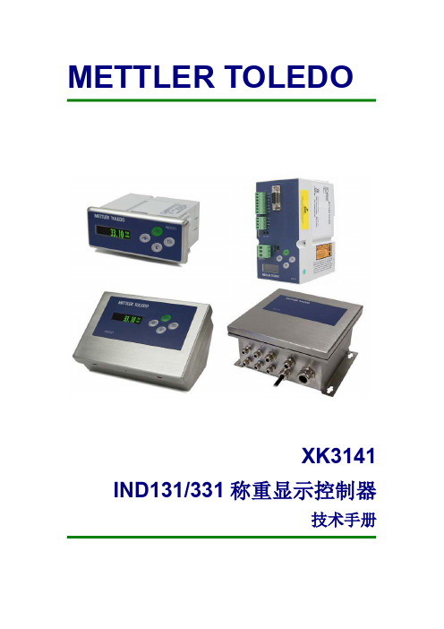
XK3141 IND131/331 称重显示控制器
技手册
目录
第 1 章 引言 .................................................................................................................................... 1 概述 .......................................................................................................................................... 1 性能指标........................................................................................................................... 1 型号 .......................................................................................................................................... 2 规格 .......................................................................................................................................... 2 危险场合的使用.....................................
METAIRE单向空调终端机说明书
SUGGESTED SPECIFICATIONS SINGLE DUCT AIR TERMINAL UNITSSECTION 1. GENERAL1.1Basic Unit. Furnish and install METALAIRE Single Duct Air Terminal Units. The units shall be the sizeand capacity as outlined in the plans and specifications. Casing dimensions shall be checked to ensure the terminals fit the available space.1.2Quality, Agency, Standards. Air terminals shall be certified under the Air Conditioning, Heating andRefrigeration Institute (AHRI) Standard 880-08 Certification Program and carry the AHRI seal. All NCvalues shall be calculated per AHRI Standard 885-08. Units with NC values calculated per AHRI-885-90 or 98 will not be accepted. Terminal units shall be either ETL® or UL® listed as a complete assembly.Terminal electrical components, including actuators and low voltage controls shall be UL® listed. Allelectrical components including both line voltage and low voltage shall be mounted in a metal control enclosure. Units shall have a single point field wiring connection. Units shall be manufactured and wired per UL-1995 and in accordance with the National Electric Code.1.3Shipping. All terminals shall be shipped as a single unit requiring no field assembly. Accessoriesincluding hot water coils and electric heaters shall be factory mounted.SECTION 2. CONSTRUCTION2.1General. Single Duct Terminal Units shall be METALAIRE Air Terminal Units. The units shall be the sizeand capacity as outlined in the plans and specifications. Casing dimensions shall be checked to ensure the terminals fit the available space.2.2Casing. The air terminals shall be constructed of galvanized steel. The casing shall be a minimum of22-gauge. The terminal primary air inlet valve shall have a round (oval or rectangular for larger sizes) inlet for field duct connection. The terminal unit discharge shall allow for a slip and drive ductconnection. Units shall have a universal control-mounting panel constructed of minimum 22-gaugesteel. Control panel shall include stand-offs to allow controls to be mounted without penetrating theterminal casing. Control panels without stand-offs are not acceptable.2.2.1Optional Sliding Door Control Panel Cover. Provide a sliding control panel cover that slidestowards the primary inlet and prevents the cover from being removed.SECTION 3. PRIMARY INLET AIR VALVE3.1Inlet Tube. Primary inlet air valve assembly shall have a seamless butt weld on round inlet tube tominimize leakage and prevent the damper from binding on overlapping seam welds. Inlet tubeswith overlapping welds or non- continuous, skipped welds are not acceptable. Inlet air valve shall have three structural beads machine formed into the tube. One external bead shall be provided for the attach- ment of flexible duct. Inlet air valves without three structural beads are not acceptable.3.2Flow Sensor. Primary inlet air valve flow sensor shall be multi-quadrant averaging sensor with flowsampling of both velocity pressure and flow differential pressure from four quadrants, and shallcontain two control ports and two accessory ports. Flow sensors sampling only velocity pressure in all four quadrants are not acceptable. Sensors reading differential pressure with fewer than 8 measuring points are not acceptable. All piping connections to the flow sensor must be made with external ports that extend through damper tube. Units with piping connections made in the primary air stream are not acceptable. Flow sensors with plastic piping connections of any kind are not acceptable. At an inlet velocity of 2000 fpm, the differential static pressure required to operate any terminal size shall not exceed 0.14” wg. for the basic terminal.3.2.1Damper Assembly. Air terminals with inlet flow sensing devices shall be provided with agasketed access door to permit removal, inspection and cleaning of the air flow sensor.3.3Damper Assembly. Damper shaft shall rotate in a self-lubricating, long life, low friction thermo-plastic bearing. Damper shaft construction shall be one piece, continuous extruded aluminum.Damper shaft end shall include a permanent cast damper position indicator. Damper tube shall be free of obstructions including damper stops to allow the free rotation of the damper. Mechanicaldamper stops located in the inlet tube are not acceptable. A flexible gasket-mounted damper blade without adhesives shall provide damper seal. Damper gasket shall include slit partitioning around the perimeter to prevent damper noise at low flows near full close off. Damper gaskets withoutperimeter slit partitioning are not acceptable. Mechanically fastened damper assembly shall be double layer, 18 gauge equivalent, galvanized steel with integral blade seal. Leakage through the damper assembly shall be less than 1% of maximum CFM at 3” static pressure.SECTION 4. INSULATION4.1Standard Fiberglass Insulation. Air Terminals shall be internally insulated with (½”or 1”) thick,1.5 lb. /ft3, dual density fiberglass. Insulation and edges shall be coated to prevent air erosion to6000FPM surface velocity. Insulation shall comply with UL 181 and NFPA 90A.4.2Optional Foil-Faced Fiberglass Insulation. Air Terminals shall be internally insulated with (½”, ¾”,1”) thick, 1.5 lb. /ft3 dual density or 1” 4 lb. /ft3 dual density, fiberglass covered with scrim backed foil facing. All surfaces and edges of the insulation shall be sealed with scrim backed foil facing so that there is no exposed fiberglass in the airstream. Insulation shall comply with UL 181 andNFPA 90A.4.3Optional Closed-Cell Foam Insulation. Air Terminals shall be internally insulated with (½”, 1”) thick,1.5lb. /ft3 density, closed-cell foam insulation and shall be Thermopure for fiber free application.Exposed fiberglass is not acceptable. Insulation shall comply with UL 181 and NFPA 255 (25/50).Material shall be chemically resistant to most hydrocarbon based solvents. Material shall not support mold growth or demonstrated degradation while subject to air erosion when tested in accordance to UL 181 and UMC 10.1.2.4.4Optional Solid Double - Wall/Metal Lined Insulation. Air Terminals shall be internally insulated andthoroughly sealed with solid metal/double walled liner to completely isolate the internal (½”, 1”) fiber glass insulation from the airstream. The insulation shall provide a virtually non-destructible, non- porous duct surface and shall inhibit bacteria growth. Internal insulation shall comply with UL 181 and NFPA 90A.SECTION 5. HOT WATER COIL5.1Construction. Hot Water Coils are to be factory mounted to the discharge outlet of the terminal. Thenumber of rows and circuits shall meet the capacities as shown in the schedule. Hot water coils shall be enclosed in a minimum 20-gauge coated steel casing allowing attachment to metal ductwork witha slip and drive connection. Fins shall be rippled and sine wave type, constructed from heavy gaugealuminum, and mechanically bonded to the tubes. Tubes shall be copper with a minimum wallthickness is 0.016” with male sweat header connections.5.2Performance. Coils shall be leak tested to 300 psi with minimum burst of 2000 psi at ambienttemperature. Coil performance data shall be rated and presented in accordance with AHRI standard 410. Coils must be ARI rated, certified and include an AHRI label. Coils that are not AHRI rated,certified or labeled AHRI are not acceptable.SECTION 6. ELECTRIC HEAT6.1Construction. Electric Reheat Coils are to be factory mounted on the discharge of the Air Terminalwith the sizes, kilowatts, steps, operating voltage, control voltage, and accessories as outlined in the plans and specifications. Heater casings shall be constructed of galvanized steel. Elementwire shall be high grade nichrome alloy rated to 45 watts per square inch density. Element wire shall be supported by moisture resistant steatite ceramics. Ceramics to be enclosed in reinforcementbrackets spaced across the heater element rack at 2” to 4” intervals. Controls shall be contained in NEMA 1 control cabinet with a hinged, latching door. A permanent wiring diagram shall be affixed to the inside of the control cabinet door for field reference. The heating element rack shall be recessed 1” into the duct to assure adequate air temperature readings for proper operation of safety switches.Each Electric Duct Heater shall be shipped with an ETL ® label certifying that it meets or exceeds the safety requirements of Standard 1996. Each heater will have an automatic primary high temperature limit switch, a manual reset high temperature limit switch, air static or fan relay type air proving switch and fusing if the heater exceeds 48 amps as required by UL®. A terminal block for line and control voltage shall be provided for simplified field wiring. A P. E. switch or contractor per step shall be provided for each stage of heat.6.2Performance. The heaters shall be ETL® listed for zero clearance, tested in accordance with UL®Standard 1995, CSA-C22.2 No. 236 and in accordance with the National Electric Code (NEC).SECTION 7. ACCESS PANELS AND MOUNTING7.1Access Panels. An optional separate bottom primary inlet access panel is available.7.2Mounting. Terminal shall include 3” wide bottom-mounting surfaces on opposite ends designedto accept bottom-mounting hardware including trapeze type. Bottom-mounting surfaces shall allow mounting hardware to be installed without interfering with access or removal of the bottomaccess panels.7.2.1Optional Mounting. Field mounted hanger brackets designed to accept threaded rods up to5/16” in. diameter are acceptable.SECTION 8. SOUND8.1Sound Ratings. The terminal manufacturer shall provide AHRI certified sound power data for radiatedand discharge sound. All NC values shall be calculated per AHRI standard 885-98. Verify soundratings for the terminal do not exceed specified value at scheduled static pressure. Sound performance shall be AHRI certified. Each individual terminal unit shall bear an AHRI label.8.2Attenuators. Sound attenuator shall be provided where scheduled to meet acoustical performancerequirements. The attenuator and terminal unit shall be single piece construction. Attenuatorinsulation shall be the same as the unit casing insulation.SECTION 9. CONTROLS9.1Digital Controls. Factory mounting and wiring of DDC controls shall be as specified in the schedule.Mounting shall include manufacturer’s flow sensor, transformer (if required by DDC controls manufac- turer), and an enclosure protecting DDC controls and wiring.9.2Analog Controls. Analog electronic controls with flow adjustments shall be as specified in theschedule and be provided by the terminal unit manufacturer.9.3Pneumatic Controls. Pneumatic controls shall be as specified in the schedule. Manufacturer shallprovide terminal units with factory set flow adjustments as required per the Terminal Unit schedule.。
ATS汽车电磁风扇产品说明书

产品图号
Product NO. 3616A02-020A0 3617A02-020A0
数量
quantity 1 1
备注
remark 3系统控制 3 system control
包含于线束总成内(Include in wiring harness) 1 包含于线束总成内
一、企业及ATS产品简介
Introduction of Elion Technology and ATS products 1.3 ATS产品系统部件 Product System Components
二、安装要求及布置匹配需注意事项 Installation requirements and notes
2.1 安装要求 installation requirements
(1)、ECU安装环境要求:务必安装在整车隔热、防水、透气的电器仓内,环境温度不超过60度为宜。 ECU installation environment requirement :must be installed in the electrical compartment of vehicle which is insulation, waterproof and breathable, the environment temperature could not exceed 60 degrees (2)、ECU安装注意事项:ECU installation notice 1)、接ECU线束之前,必须切断整车总电源。 Before access ECU wiring harness please cut off main vehicle power 2)、每条线束均有明确的中(英)文标签,指明接线位置。 Each wiring harness has a clear Chinese and english label and specifies the terminal location 3)、整车如果要电焊作业,则需切断电源,拔下线束航插。 If vehicle need welding work , you need to cut off the power and unplug the wiring harness aircraft plug (3)、ECU主线束安装:ECU wiring harness installation 将线束的航空插件与ECU总成连接,线束总成上两个针的航空插件对应旁边有个小的航空插件分别对应的与ECU 模块上的接口连接并旋紧。 Aircraft plug of wiring harness connected with ECU assembly, with the two-pin plug of wiring harness assembly next to a small plug-ins corresponding to the respective air plug-in module interfaces with the ECU connected and then tightened
8808智能监控并车系统说明书

8800远程智能监控系统简介8808智能监控并机系统说明书前言柴油发电机组的控制屏用于实现对机组的启动、运行、停机、紧急停机等操作,部分型号的控制屏还具备实现通讯及进行远程监控的功能,这就为用户将柴油发电机组顺利纳入集中监控网络提供了可能。
同时,它们还具有当机组发生故障时,可根据其严重程度和性质自动对机组实施停机保护或发出报警信号等功能,同时指示出故障种类,为柴油发电机组的可靠运行、方便操作和故障查找等提供了保障和参考。
所有类型的启动控制系统屏均选用进口或合资企业生产的优质元器件,可确保机组安全稳定运行。
所有类型的启动控制系统屏均可按加装预热装置控制单元。
不同型号的启动控制屏分别可以完成不同的功能,用户可根据不同的使用要求予以选择。
我司的控制屏分为手动和自动两大类,8100手动控制屏是我司的标准配置,自动控制屏有8200,8800和8808型自动控制屏。
8200控制屏具备基本的自动控制功能;8800控制屏属于远程智能监控屏,大屏幕多行全中文液晶显示界面,具备遥控、遥信、遥测的功能,随机免费提供全中文上位机监控软件及MODBUS通讯协议;8808控制屏属于智能监控并车屏,该屏在8800控制屏的基础上加上并车的控制功能。
以下就客户购买的具体型号的控制屏进行具体的说明。
8808智能监控并车系统一、概述:COOLTECH 8808智能监控并车系统,结构简单紧凑,功能十分强大,除具有基本的发电机组三遥功能外,还具有控制最多32台机组全自动并车,机组与市电电网并联,自动按比例实现有功和无功负载的无差分配;提供标准的计算机通讯接口,用户可以用PC机直接就近连接或通过公用电话网远程拔号上网监控多台机组并车系统。
发电机组控制保护功能1.手动和自动控制单台机组的启停及输出空气开关;2.LCD宽屏液晶参数显示:油压、水温、电池电压、运行时间等油机参数,三相相电压、线电压、线电流、频率、功率因数、有功功率、无功功率、电度等电参数,并联汇流母线电压、母线与发电机电压、频率、相位差等同步参数;3.发电机组低油压、高水温、超速、超频、速度信号丢失、起动失败、过流、电压过高或过低、逆功率保护停机;4.发电机组充电失败、水温高、油压低、电池电压低、传感器故障报警;5.类似黑匣子的历史事件记录;6.参数设置授权控制;7.方便功能扩展。
阿特拉斯空压机说明书
2
2991 7092 20
使用说明书
3.10 3.11 3.12 3.13 3.14 3.15 3.16 3.17 3.18 3.19 3.20 3.21 3.22 3.23 3.24 3.25 3.26 3.27 3.28 3.29 3.30 3.31 3.32 3.33
查阅运行时间.......................................................................45 查阅电动机起动次数.................................................................46 查阅控制器运行时间.................................................................47 查阅加载时间.......................................................................47 查阅加载继电器.....................................................................47 查阅/复位保养定时器 ...............................................................48 在本地、远程或 LAN 控制之间进行选择................................................49 查阅/修改 CAN 地址控件.............................................................49 查阅/修改 IP、网关和子网掩码.......................................................51 查阅/修改压力带设置值..............................................................53 修改压力带选择.....................................................................54 查阅/修改保养定时器设置............................................................55 查阅/修改温度单位..................................................................55 查阅/修改压力单位..................................................................56 激活断电后自动重新起动功能.........................................................56 在星/三角起动或直接起动之间进行选择................................................56 查阅修改加载延迟时间...............................................................57 查阅修改最小停机时间...............................................................57 激活密码保护.......................................................................58 激活加载/卸载远程压力传感功能......................................................58 查阅/修改保护设置值................................................................59 测试屏幕...........................................................................60 WEB 服务器.........................................................................61 可设定的设置值.....................................................................70
凯克斯设备说明书中文版(仅作参考)
名义直径: 总长度:
3.18 mm (0.125″) 6200mm(244″)
KX170 机械说明书(B)
7/21
Kayex 机密
KX170 设备说明书
2.5 热屏提升
在设备的炉盖上设计有两点式的热屏提升机构。热屏的位置可以通过在 手动模式下的触摸屏来控制,同样也可以通过自动模式下的计算机控 制。自动模式下通过斜率表来控制移动。两个热屏提升口在炉盖上相隔 180 度分布。
极限真空压力: 泄漏率(压力上升速率):
一般 25mtorr(该值是由真空泵和真空系 统决定) 50mtorr/hr
2.6.5. 氧化物控制系统
主真空系统在两个主真空接口的下游处都配置了一个空气注射阀用来 控制氧化物,通过计算机可以同时控制两个阀的开启,每个注射口的流 量稳定在大约或少于 5 升/分钟。
305mm(12″) 2800mm(110″)
KX170 机械说明书(B)
4/21
Kayex 机密
KX170 设备说明书
2.1.7 副室延长室
副室延长室是位于副炉室上部的一个圆筒形腔体。
延长室高度: 延长室内径:
508mm(20″) 191mm(7.5″)
2.1.8 水平调整器
水平调整器是封闭副室延长室上部并用来支撑籽晶提升的装配组件。通 过调整上法兰可以使籽晶旋转轴铅直垂直。水平调整器有两个氩气接入 口,一个熔体温度计接口,一个辅助真空接口。
隔离阀内径:
305mm(12″)
2.1.6 副炉室(接收室)
副炉室是位于隔离阀上的一圆筒形腔体。副炉室上设有便于操作者观察 的观察窗口(1)和籽晶位置监测口(2)。在副炉室上方的水平调整器 设有氩气进气接口(2),熔体测温计(1),一个辅助真空系统抽真空接 口。在副炉室上端还有一个清扫口。
M-System 远程 I O R5 系列通信模块规格书说明书

远程 I/O R5 系列通信模块机型: R5-NM1① ①在下列代码中选择。
(例如: R5-NM1/Q)・特殊规格 (例如: /C01)①附加代码◆特殊规格未填写:无特殊规格/Q:特殊规格(请从特殊规格之项另行选择)/C01: 硅涂层/C02: 聚氨酯涂层/C03: 橡胶涂层 可从本公司的网站下载组态软件。
将本产品连接到电脑时,需要专用的连接电缆线。
所需专 用电缆线的型号请参照本公司网站的下载网站或组态软件 的使用说明书。
注)此软件的运作状况是在日文版与英文版OS上确认的。
・Modbus: 连接器型欧式端子盘 (适用电缆线: 0.2~2.5mm2、露线长度为7mm)・内部通信总线: 连接到底座(机型: R5-BS)上・内部电源: 由底座(机型: R5-BS)提供隔离: Modbus-内部通信总线・内部电源间RUN显示灯: 红/绿2色LED通信正常时亮绿色灯;接收数据时亮红色灯(用DIP开关进行切换)ERR显示灯: 红/绿2色LED通信异常时绿色灯亮灯/闪烁;发送数据时,亮红色灯(用DIP开关进行切换)数据占有区设定: 用侧面的DIP开关设定占有区1或占有区2传输距离: 500m以下传输电缆线: 双绞屏蔽线 (CPEV-0.9 ø)通信设定: 用侧面的DIP开关设定・数据: RTU (二进制)、ASCII・奇偶校验: 无奇偶校验、偶数校验、奇数校验・传输速度: 4800、9600、19.2k、38.4k (bps)节点地址设定: 01~F7 (用DIP开关设定)使用湿度范围: 30~90%RH (无冷凝)使用大气条件: 无腐蚀性气体和严重尘埃安装: 安装在底座 (机型: R5-BS) 上重量: 约100g隔离强度: Modbus-内部通信总线・内部电源间2000V AC 1分钟电磁兼容指令(EMC指令) EMI EN 61000-6-4 EMS EN 61000-6-2RoHS指令■左视图■数据和控制功能代码名 称01Read Coil Status ○Digital output from the slave (read ⁄write )02Read Input Status○Status of digital inputs to the slave (read only )03Read Holding Registers ○General purpose register within the slave (read ⁄write )04Read Input Registers ○Collected data from the eld by the slave (read only )05Force Single Coil○Digital output from the slave (read ⁄write )06Preset Single Register ○General purpose register within the slave (read ⁄write )07Read Exception Status 08Diagnostics ○09Program 48410Poll 48411Fetch Comm. Event Counter Fetch a status word and an event counter12Fetch Comm. Event Log A status word, an event counter, a message count and a eld of event bytes13Program Controller 14Poll Controller15Force Multiple Coils○Digital output from the slave (read ⁄write )16Preset Multiple Registers ○General purpose register within the slave (read ⁄write )17Report Slave ID Slave type ⁄‘RUN ’status18Program 884⁄M8419Reset Comm. Link20Read General Reference 21Write General Reference 22Mask Write 4X Register 23Read ⁄Write 4X Registers 24Read FIFO Queue■例外代码代码名称01Illegal Function○Function code is not allowable for the slave02Illegal Data Address○Address is not available within the slave03Illegal Data Value○Data is not valid for the function04Slave Device Failure05Acknowledge06Slave Device Busy07Negative Acknowledge08Memory Parity Error■诊断代码代码名称00Return Query Data○Loop back test01Restart Comm. Option○Reset the slave and clear all counters02Return Diagnostic Register○Contents of the diagnostic data(2 bytes)03Change ASCII Input Delimiter○Delimiter character of ASCII message04Force Listen Only Mode○Force the slave into Listen Only Mode数据占有区“1”时,所有的输入输出模块的输入输出数据为1个字。
ATS子系统HMI工作站操作手册

卡斯柯信号有限公司2016年05月11日签署页编写/职务日期审核/职务日期批准/职务日期姓名魏来张萌杨阳签字姓名签字姓名签字修订记录编号章节名称修订内容简述修订日期修订后版本修订人1 全文创建全文2012-05-17 V0.0.1 张萌2 全文根据评审意见修改2012-05-18 V1.0.0 张萌3 全文3.1.1修改界面结构图3.5.3.2列车驾驶模式修改-加入eam模式3.5.4增加临时限速显示3.6.15/3.6.16增加overlap显示3.7.6增加车站的列车操作功能3.8 增加临站信息显示根据产品手册对操作注意事项进行补充更新casco000019992012-08-03 V1.0.1 张萌4 全文根据安全须知修改如下章节内容:3.1.2执行命令的操作方式3.2告警/事件显示和确认3.7.2.1设置进路3.7.7.8站遥控,紧急站控切换3.7.2.1设置进路3.7.7.8站遥控,紧急站控切换增加4.1投入运营前准备4.2紧急情况处理策略casco000025052012/8/20 V1.0.2 张萌5 全文根据V1.1.0版本安全限制,更新文档2012/10/8 V1.0.3 黄柒光修订记录编号章节名称修订内容简述修订日期修订后版本修订人6 全文根据审核意见修改:1.删除道岔封锁和区段封锁字样2. 3.5.2.2 章修改信号机绿黄显示含义;删除线路阻挡信号机、复式信号机描述,增加灯丝断丝显示描述根据cr casco00003158,更新站名截图并升级为正式版本2012/10/9 V1.1.0 黄柒光7 全文根据最新操作手册模板更新文档2016/5/11 V1.2.0 魏来目录1引言 (9)1.1文档目的 (9)1.2术语定义 (9)2总体介绍 (9)2.1产品的前景 (9)2.2产品功能分配 (9)2.3运行环境 (10)3 ATS车站工作站软件人机界面 (10)3.1主界面 (10)3.1.1界面构成 (10)3.1.2执行命令的操作方式 (12)3.1.3鼠标操作 (12)3.1.4键盘操作 (13)3.2告警/事件显示和确认 (13)3.3主要设备状态显示 (14)3.4时间显示 (14)3.5站场信号显示 (15)3.5.1静态显示数据 (15)3.5.2动态显示数据 (15)3.5.3列车识别号显示 (25)3.5.4 临时限速TSR (28)3.6其他表示信息 (28)3.6.1道岔电流表 (28)3.6.2邻站通信状态表示 (28)3.6.3进路排列故障 (29)3.6.4站台停稳状态 (29)3.6.5站台紧急关闭 (29)3.6.6站台屏蔽门状态 (29)3.6.7全站封锁按钮倒计时 (30)3.6.9区故解按钮操作计数 (30)3.6.10总人解按钮操作计数 (30)3.6.11引导总锁按钮操作计数 (31)3.6.12自动回转道岔倒计时 (31)3.6.13信号被封锁状态 (31)3.6.14隔断门/防掩门显示 (31)3.6.15 延续防护Overlap状态 (32)3.6.16 延续防护Overlap倒计时 (32)3.7信号与列车操作界面 (33)3.7.1设备上下文敏感菜单 (33)3.7.2信号与进路操作 (34)3.7.3站台操作 (43)3.7.4区段操作 (46)3.7.5道岔操作 (44)3.7.6列车操作 (51)3.7.7其他操作 (57)3.8邻站显示 (62)3.9列车运行信息显示 (63)3.10信息管理和维护 (64)3.10.1报警过滤设置 (64)3.10.2登录 (65)3.10.3注销 (60)3.10.4修改密码 (62)3.10.5控制区域设置 (64)4 投入运营准备及紧急情况处理策略 (67)4.1 投入运营前准备 (67)4.2 紧急情况处理策略 (67)5 主要操作场景 (68)5.1 车站值班员控制 (68)5.3 系统降级到站控模式 (69)5.4 车站ATS设备故障 (69)1引言1.1文档目的本手册主要对ATS系统的现地工作站的人机界面进行说明,阐述各项功能操作步骤和注意事项。
Destaco 自动化产品型号说明说明书

EXPRESS DELIVERY FOR WORLD-CLASS AUTOMATION PRODUCTS GRIPPERS • ROTARIES • SLIDESTOOL CHANGERS • ESCAPEMENTSElectric GripperLinear SlidesEscapementsRotary Actuators Tool ChangersTool ChangersProduct Name Lead Time: 3-Day 10 Day Consult Factory xG100 Series All Models, All SizesDPDL Series MetricOnlyDPDL-047M-038DPDL -056M-050DPDL-125M-100-B, -E, -V option-CR, -S option,Imperial UnitsDPDS Series MetricOnly DPDS-047M-013 (-B)DPDS-056M-019 (-B)DPDS-088M-025 (-B)DPDS-125M-038 (-B)DPDP-250M-075 (-B)-V option-CR, -S option,Imperial UnitsDPG Series Imperial/Metric DPG-10(M)-1 (-C, -O)DPG-10(M)-2 (-C, -O)DPG-10(M)-3 (-C, -O)DPG-10(M)-4 (-C, -O)-LF, -RF, -NS, -Voption-T option,DPP Series Metric Only DPP-10M-06 (-C)DPP-10M-12 (-C)DPP-14M-15 (-C)DPP-20M-25 (-C)-NS, -V optionRP Series Imperial/MetricRP-5 (M) (-V)RP-10 (M) (-V)RP-11 (M) (-V)RP-12 (M) (-V),RP-15 (M) (-V)RP-17 (M) (-V)RP-18 (M) (-V)-D, -FS, optionRP-P Series Imperial/MetricRP-25P (M)RP-50P (M)RP-100P (M)-V optionRPS Series Imperial/Metric(select models)RPS-11RPS-12 (M) (-C)RPS-17 (M) (-D) (-C)-O, -V optionRPL Series Imperial/Metric RPL-1 (M)RPL-2 (M)RPL-3 (M)RPL-4 (M)-NS, -V optionRPLC Series Imperial/Metric RPLC-1 (M)RPLC-2 (M)RPLC-3 (M)RPLC-4 (M)-NS, -V optionRPM Series MetricOnly RPM-1MRPM-2MRPM-3M-V optionRPMC Series MetricOnly RPMC-1MRPMC-2MRPMC-3M-V optionStandard Product Lead Time with OptionsLead Time: 3-Day 10 Day Consult FactoryDPE-200 Series MetricOnly DPE-200-25N/A N/A Electric Parallel Grippers2-Jaw Parallel GrippersLead Time: 3-Day 10 Day Consult FactoryRTH Series Metric Only RTH-1M (-L)RTH-2M (-L)RTH-3M (-L)RTH-4M (-L)RTH-5M (-L)RTH-6M (-L)-C, -O, -SP-V2-Jaw Heavy-Duty Parallel Grippers3-Jaw Parallel GrippersLead Time: 3-Day 10 Day Consult FactoryDCT Series Metric Only DCT-12MDCT-16M-RE, -V option-SD, -BRRA Series Imperial/Metric(select models)RA-5 (M)RA-6 (M)RA-10RA-15RA-90-V option All other modelsAngular Grippers Lead Time: 3-Day 10 Day Consult FactoryDPW Series Metric Only DPW-250M-2 (-W)DPW-375M-1 (-W)DPW-375M-2 (-W)DPW-500M-1 (-W)DPW-500M-2 (-W)-NS, -V optionRPW Series Metric OnlyRPW-250MRPW-375M-1RPW-375M-2RPW-500M-1RPW-500M-2RPW-625M-1RPW-625M-2RPW-750M-NS, -V option Imperial UnitsRPR Series Metric Only RPR-200Feed EscapementsLead Time: 3-Day 10 Day Consult FactoryRFE Series Metric OnlyRFE-11MRFE-12MRFE-13M-V option-T optionImperial Units Lead Time: 3-Day 10 Day Consult FactoryRR Series Light Duty Imperial/Metric(select models)RR-18-45 (-90) (-180)RR-28-90 (-180)RR-36M-90 (-180)RR-46M-90 (-180)-S, -V option-M (size 36 & 46 units)-CR, -T Option,Other ModelsRR SeriesMedium Duty Metric Only RR56M-180-A-MRR66M-180-A-MRR76M-180-A-M-45, -90,-S, -V option Imperial ModelsRotary ActuatorsLinear SlidesLead Time: 3-Day 10 Day Consult FactoryDLB Series Imperial Only DLB-10-B (-L)-B (-C)DLB-12-B (-L)-B (-C)DLB-16-B (-L)-B (-C)-U option-T, -A,-N,-R, -S, -V options,Metric unitsDLT Series Metric OnlyDLT-08M-B-CDLT-10M-B-B (-C)DLT-12M-B-B (-C)DLT-16M-B-B (-C)-E, -L, -U options(for 3 day Xpress items)DLT-20M-B-B,DLT-25M-B-B-B (08 bearing),-T, -A,-N, -R, -S, -VoptionsDLM Series Metric Only DLM-07M-25DLM-09M-50DLM-12M-25-D, -P options Consult factoryfor other SizesMPS Series Imperial Only MPS-1-1 (-2) (-3) (-4)MPS-2-1 (-2) (-3) (-4)-V optionTool ChangersLead Time: 3-Day 10 Day Consult FactoryRHC Series NPT Ports Only RHC-1M-RRHC-1M-TRHC-2M-RRHC-2M-T-V option All other modelsRQC Series NPT Ports OnlyRQC-200NRQC-400NRQC-800N-LO, -CD, -CPLock Sensing,-E19, -FN ModulesBSPP, BSPTport optionsAll other optionsand modulesRTP Series NPT Ports OnlyRTP-200RTP-400RTP-800-E19,-FN ModulesAll other optionsQC Series NPT Ports OnlyQC-30-E15QC-60-E15QC-150-E15-E26 Module(QC60/QC150 model)E10, E12, -10P,All other optionsTP Series NPT Ports OnlyTP-30-E15TP-60-E15TP-150-E15All other options3 DAYWorkholding •Widest variety of workholding products •High durability and reliability•Flexible solutions for all applications •Custom products for unique requirementsAutomation•Broad range of engineered automation products •Complementary products for modular integration •Unmatched accuracy, reliability and performance •Unparalleled global sales, service and engineering support 1025 Doris RoadAuburn Hills, MI 48326Phone:1.888.DESTACOFax:1.248.836.6901Email:*********************Web: NORTH AMERICADE-STA-CO HeadquartersAuburn Hills, MichiganTel: 1.248.836.6700Toll Free: 1.888.DESTACOMarketing:********************* CustomerService:*************************** Charlevoix, MichiganTel: 1.888.DESTACOCustomerService:*************************** Wheeling, IllinoisTel: 1.800.645.5207CustomerService:*****************Red Wing, Minnesota (Central Research Laboratories) Tel: 1.651.385.2142CustomerService:*****************SOUTH AMERICABrazilTel: +55-11-2923-6640CustomerService:********************ASIAThailandTel: +66-2-326-0812 CustomerService:**************** ChinaTel: +86-21-6081-2888 CustomerService:***************** IndiaTel: +91-80-41123421-426 CustomerService:*****************EUROPEGermanyTel: +49-6171-705-0 CustomerService:****************** FranceTel: +33-1-3996-5000 CustomerService:****************** UKTel: +44-1902-797980 CustomerService:************** SpainTel: +34-936361680 CustomerService:***************** NetherlandsTel: +31-297285332 CustomerService:*******************GLOBAL LOCATIONS© Copyright, 2015 DE-STA-CO. All rights for layout, photos and text rest with the publisherDE-STA-CO. All photomechanical or other reproductions only with our express permission.All sales are based on our terms and conditions of sale, delivery and payment.DSC_AUTOXP-B_0115_US_3.5K SOTAD。
诺赛克说明书
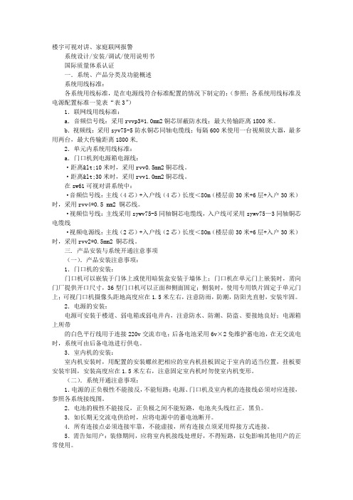
楼宇可视对讲、家庭联网报警系统设计/安装/调试/使用说明书国际质量体系认证一.系统、产品分类及功能概述系统用线标准:各系统用线标准,是在电源线符合标准配置的情况下制定的:(参照:各系统用线标准及电源配置标准一览表“表3”)1.联网线用线标准:a.音频信号线:采用rvvp3*1.0mm2铜芯屏蔽防水线;最大传输距离1800米。
b.视频线:采用syv75-5防水铜芯同轴电缆线;每隔600米使用一台视频放大器,最多用两台,最大传输距离1800米, 2.单元内系统用线标准:a.门口机到电源箱电源线:·距离<10米时,采用rvv0.5mm2铜芯线。
·距离<30米时,采用rvv1.0mm2铜芯线。
在sw61可视对讲系统中:·音频信号线:主线(4芯)+入户线(4芯)长度<80m(楼层前30米+6层+入户30米)时,采用rvv4*0.5 mm2 铜芯线。
·视频信号线:主线采用sywv75-5同轴铜芯电缆线,入户线可采用sywv75—3同轴铜芯电缆线·视频电源线:主线(2芯)+入户线(2芯)长度<80m(楼层前30米+6层+入户30米)时,采用rvv2*0.5mm2 铜芯线。
三. 产品安装与系统开通注意事项(一).产品安装注意事项:1.门口机的安装:门口机可以嵌装于门体上或使用暗装盒安装于墙体上;门口机在单元门上嵌装时,需向门厂提供开口尺寸,36型门口机可以正面和侧面固定;侧装时,使用专用铁片固定于单元门上;可视门口机摄像头距地高度应在1.5米左右,注意防雨,防潮,防阳光直射,安装牢固。
2.电源的安装:电源可安装于楼道、弱电箱或弱电井内,注意防水、防潮、防盗、要接地良好;电源箱上所带的白色平行线用于连接220v交流市电;后备电池采用6v×2免维护蓄电池,在无交流电时,系统可由后备电池进行供电。
3.室内机的安装:室内机安装时,用配置的安装螺丝把相应的室内机挂板固定于室内的适当位置,挂板要安装牢固,安装高度应在1.5米左右,注意固定室内机时勿使室内机变形。
ATS操作员手册V1.0.doc

文档来源为:从网络收集整理.word版本可编辑.欢迎下载支持.FZy型ATS(CTC)系统FZy-ATS(CTC) System操作员手册ATS Operator Manual编制:年月日审核:年月日批准:年月日北京市华铁信息技术开发总公司中国铁道科学研究院通信信号研究所北京锐驰国铁智能运输系统工程技术有限公司文件序号文件描述ATS操作员手册V1.0NOTICEThis document has been produced by CARS. The document is confidential and shall not be disclosed to third part without the consent of CARS.1序言............................................................................................................. 错误!未定义书签。
2系统概况 ..................................................................................................... 错误!未定义书签。
3系统功能 ..................................................................................................... 错误!未定义书签。
3.1系统登陆 .................................................................................................. 错误!未定义书签。
3.2系统基本窗口 .......................................................................................... 错误!未定义书签。
芝锋 HMi VU 系列操作员界面说明书
HM i VU Series Instruction LeafletContentsDescription ............................................ PagePreface (1)Safety Precautions (1)Installation (3)Wiring (4)Basic Inspection (4)Hardware Features (7)Panel Cut-Out (17)Specifications (19)HM i VU Series Instruction LeafletEATON CORPORATION 1PrefaceThank you for purchasing Eaton’s HM i VU series operator interface. This quick start guide will be helpful in the installation, wiring and inspection of your Eaton operatorinterface. Before using the product, please read this quick start guide to ensure correct use. You should thoroughly understand all safety precautions before proceeding with the installation, wiring and operation. Please observe the following precautions:⏹Install the product in a clean and dry location free from corrosive and flammable gases or liquids.⏹ Ensure that all wiring instructions andrecommendations are followed.⏹ Ensure that the operator interface iscorrectly connected to a ground. The grounding method must comply with the electrical standard for the country of final installation (NFPA 70: National Electrical Code, 2005 Ed).⏹ Do not modify or remove wiring whenpower is applied to the operator interface.⏹ Do not touch the power supply duringoperation or it may cause electric shock.⏹ For the information on HMiSoftinstallation and use, please refer to the HMiSoft manual at /oi .If you have any questions during operation, please contact an authorized local distributor or Eaton sales representative. The content of this quick start guide may be revised without notice. Please consult an authorized distributor or download the most up to date version at /oi .Safety PrecautionsCarefully note and observe the followingsafety precautions when receiving, inspecting, installing, operating, maintaining and troubleshooting. The following words,DANGER, WARNING and STOP are used to mark safety precautions when using Eaton’s operator interface. Failure to observe these precautions may void the warranty!InstallationWiringHM i VU Series Instruction LeafletEATON CORPORATION 2OperationM odify wiring during operationmay result in electric shock orpersonal injury. U sing a sharp or pointed objectto activate screen controls may result in damage to thetouchscreen and improper operation.Wiring MethodCommunication WiringMaintenance and InspectionE lectrical shock and damage tounit may result from contact withany internal electronic assemblies.First remove power and then disconnect the terminals to avoid electrical shock and damage to unit.A ccessing the unit’s internal electric assemblies will void the warranty. In addition, an electrical charge with hazardous voltages may reside in the operator interface after power has been removed for 10 minutes or longer which may result in electrical shock and damage to the unit.T urn the power off before changing backup battery and check system settings afterchanges are made. Note that the application and all data will be cleared after a battery change.O bstruction of ventilation holes during operation may result in malfunction caused by overheating.HM i VU Series Instruction LeafletEATON CORPORATION 3InstallationInstallation NotesThe panel thickness should be 5 mmor less for proper mounting. Installation Method:Step 1:Ensure the pre-installed waterproof gasket ispresent and properly aligned.Step 2:Insert fasteners into the operator interface slots. All should be finger tight initially.Step 3:Torque all fasteners to 6.17lb-inch (0.7N-M) Over torque may cause damage to the operator interface housing.Step 4:Maintain a minimum spacing of 60mm from the back of the operator interface ventilation holes.HM i VU Series Instruction LeafletEATON CORPORATION 4Wiring•Please observe the following wiring notes.⏹Use shielded twisted-pair cables for wiring.Power supply connector:Basic InspectionHM i VU Series Instruction LeafletEATON CORPORATION 5Pin Definition for CommunicationsHMIVU04CUNBENote: Blank = No Connection.HMIVU06CUNB1 / HMIVU07CUNBE Note: Blank = No Connection.Note1: Blank = No Connection.Note2: HMIVU06CUNB/HMIVU07CUNBE models do not support RS-422 flow control function.HMIVU08CUNBE / HMIVU10WCUNBEHM i VU Series Instruction LeafletEATON CORPORATION 6Note1: Blank = No Connection.Note2: When COM2 port is used for RS-232 flowcontrol, i.e. RTS and CTS signals are used for flow control, COM3 port will become disabled.Note3: When COM2 port is used for RS-422 with flowcontrol, COM3 Port pins 1, 4, 6, and 9 are used for the signals, RTS+, CTS+, RTS- and CTS- as shown in brackets.Note2: When COM2 port is used for RS-422 with flow control, COM3 Port pins 1, 4, 6, and 9 are used for the signals, RTS+, CTS+, RTS- and CTS- as shown in brackets.Note: Blank = No Connection.HM i VU Series Instruction LeafletEATON CORPORATION 7Hardware FeaturesHMIVU04CUNBE (Front View)BAHM i VU Series Instruction Leaflet HMIVU04CUNBE (Rear View)EATON CORPORATION 8HM i VU Series Instruction LeafletEATON CORPORATION 9HMIVU06CUNB1 (Front View)BHM i VU Series Instruction Leaflet HMIVU06CUNB 1(Rear View)HM i VU Series Instruction Leaflet HMIVU07CUNBE (Front View)HM i VU Series Instruction LeafletHMIVU07CUNBE (Rear View)AHM i VU Series Instruction LeafletHMIVU08CUNBE (Front View): Power LED IndicatorLights in green when power is applied.: Operation LED Indicator (Blue)The operation LED indicator blinks in blue when communicating or accessing data: Alarm LED Indicator (Red)The alarm LED indicator blinks in red when one of the alarms is on.HM i VU Series Instruction Leaflet HMIVU08CUNBE (Rear View)HM i VU Series Instruction LeafletHMIVU10WCUNBE (Front View)D: Power LED IndicatorLights in green when power is applied.: Operation LED Indicator (Blue)The operation LED indicator blinks in blue when communicating or accessing data: Alarm LED Indicator (Red)The alarm LED indicator blinks in red when one of the alarms is on.HM i VU Series Instruction Leaflet HMIVU10WCUNBE (Rear View)HM i VU Series Instruction LeafletPanel Cut-OutHMIVU04CUNBEHMIVU06CUNB1HMIVU07CUNBEHM i VU Series Instruction Leaflet HMIVU08CUNBEHMIVU10WCUNBEHM i VU Series Instruction Leaflet SpecificationsHM i VU Series Instruction LeafletSpecificationscurrent is supplied to HM i. The life of LED backlight shown is an estimated value under 25o C normal temperature and humidity conditions.2) USB Host port can provide up to 5V/ 500mA of power.EATON CORPORATION 20HM i VU Series Instruction Leaflet3) The withstand voltage of the isolated power circuit is 1500V peak for 1 minute.4) The value of the power consumption indicates the electrical power consumed by HM i only withoutconnecting to any peripheral devices. In order to ensure the normal operation, it is recommended to use a power supply which the capacity is 1.5 ~2 times the value of the power consumption.5) For further details, please visit the Eaton website /electrical.EATON CORPORATION 21HM i VU Series Instruction Leaflet。
红狮Crimson 2 系列G3 HMI设备说明书

G3系列HMI,图片小于实际尺寸。
web和网络支持多种不同类型的硬件。
可、驱最简洁、最灵活的软件,请访问了解我们的全线HMI产品(HMi)B操作界面 – H M I板上的以太网端口公开各类数据,允许对诊断信息或者数据记录器记录的值进行远程访问。
CompactFlash (CF 卡)帮助实现几乎无限的数据存储能力集成CF 卡插槽可以插接便宜、常见的I 类和II 类CompactFlash 卡,让您能够轻松地收集、保留以及传输数据。
如需更新已在客户处安装的设备内部的数据库,您可以通过Crimson 将该数据库的副本保存到CompactFlash 卡中,把该卡交付给客户,然后让G3从该卡中加载数据库。
USB 端口让数据传输与下载 更加快捷G3 HMI 系列有一个方便的USB 端口,可用于从PC 中快速下载配置文件,还可用于将趋势和数据记录快速上传到PC 中进行分析。
强大的处理能力G3 HMI 系列配备板载32位处理器,拥有无与伦比的计算能力。
功能齐全的Crimson 软件包含内置的“C ”编译器,可用于为复杂应用、配方处理、实时计划、数学表达式求值等等创建自定义程序。
配置与编程更迅捷Crimson 2是强大的基于图标的配置、显示、控制以及数据记录工具集合,它们专为充分利用G3 HMI 系列的架构而设计。
多数简单应用程序可通过分步过程快速设置,以配置通信协议、定义要访问的数据标记以及创建用户界面。
一整套拖放图形项不但简化了界面的创建,而且能够产生专业效果。
编程、数据记录和配置G3的web 服务器等更多高级功能既直观又容易启用。
价格最低的全功能HMI只需比许多精简版HMI 更低的价钱,您就可以增加只有G3 HMI 系列才提供的强大功能和易性。
G3系列标配有三个串行通信端口、以太网、协议转换器、USB 和CF 卡插槽。
并且,无需支付额外费用,您就可以获得功能齐全的Crimson 2软件,它包含拖放配置和数据标识功能、易用的界面工具、灵活的编程环境、强大的数据记录功能以及我们独有的虚拟面板和用于远程访问与控制的web 服务器功能。
日立空调技术手册
4. 选择功能..................................................................................................................................................4-1 4.1 室内机(RPF(l) – FSG(E),RPK-FSGM 和 RPC-FSG1 系列).......................................................4-1 4.1.1遥控器开/关功能........................................................................................................................4-1 4.1.2电源开/关功能1(电源接通时的自动功能)..........................................................................4-5 4.1.3电源开/关功能2(电源故障后的重启功能)..........................................................................4-5 4.1.4室内电热调控器的控制..............................................................................................................4-6 4.1.5遥控温度传感器的操作控制......................................................................................................4-7 4.1.6外部输入改变制冷或制热模式的设定(水平信号输入)......................................................4-7 4.1.7截取操作信号..............................................................................................................................4-8 4.2 室内机(RPI-FSG1,RCI-FSG1 和 RCD-FSG1 系列) ...................................................................4-11 4.2.1室内机印刷电路板输入输出设置..............................................................................................4-11 4.2.2温度遥控器功能..........................................................................................................................4-13 4.2.3遥控器开/关功能.........................................................................................................................4-14 4.2.4电源开/关功能1(电源接通时的自动功能)..........................................................................4-18 4.2.5电源开/关功能2(电源故障后的重启功能)..........................................................................4-18 4.2.6室内电热调控器的控制..............................................................................................................4-19 4.2.7遥控温度传感器的操作控制......................................................................................................4-20 4.2.8外部输入改变制冷或制热模式的设定......................................................................................4-20 4.2.9截取操作信号..............................................................................................................................4-21 4.3 室外机...................................................................................................................................................4-25 4.3.1指令.............................................................................................................................................4-27 4.3.2强制停机......................................................................................................................................4-27 4.3.3固定运行模式..............................................................................................................................4-28 4.3.4霜冻传感器..................................................................................................................................4-28 4.3.5除霜条件的改变..........................................................................................................................4-29 4.3.6制热模式下温控关闭时对室内风机的控制..............................................................................4-30 4.3.7各个季节里的制热操作..............................................................................................................4-30 4.3.8各个季节里的制冷操作..............................................................................................................4-31 4.3.9夜间转换(低噪音)运行..........................................................................................................4-32 4.3.10截取室外机印刷电路板的信号..................................................................................................4-334.4遥控器PC-2H2.....................................................................................................................................4-35 4.4.1零件名称......................................................................................................................................4-35 4.4.2同步运行......................................................................................................................................4-36 4.4.3双遥控器操作系统......................................................................................................................4-38 4.4.4功能设定选择..............................................................................................................................4-39 4.4.5遥控器功能选择..........................................................................................................................4-42 4.4.6 寻址(ADDS)和制冷剂循环编号(RN)显示 .....................................................................4-474.5无线遥控器PC-LH3 ............................................................................................................................4-48 4.5.1零件名称......................................................................................................................................4-48 4.5.2室内机组并列安装的识别..........................................................................................................4-49 4.5.3同步运行......................................................................................................................................4-50 4.5.4紧急操作......................................................................................................................................4-52 4.5.5选择功能设定..............................................................................................................................4-53 4.5.6无线遥控器的选择功能..............................................................................................................4-54 4.6七日时控器,PSC-3T..........................................................................................................................4-55 4.7中央控制器PSC-3S1 ...........................................................................................................................4-57 4.7.1零件名称......................................................................................................................................4-57 4.7.2系统.............................................................................................................................................4-58 4.7.3中央控制器的操作步骤..............................................................................................................4-60选择功能(4.1室内机) 4.选择功能4.1室内机(RPI(I) – FSG(E),RPK-FSGM和RPC-FSG1系列)4.1.1遥控器开/关功能该功能提供远程自动停机或系统启动的控制。
合信技术CoPanel系列HMI安装手册

处理器
32bit RISC CPU
资料存储(SD 卡)
4MB
实时时钟
有
FLASH 存储卡
无
通信接口
COM1
9 针母头,RS485(连接 PLC 等)
COM2
9 针母头,RS485(连接 PLC 等)
USB P1
主设备接口,连接 USB 从设备,如 USB 鼠标,U 盘等。(不
能与 USB P0 同时使用)
配线方法
配线时请将快速接头从人机界面的本体上拆下来。 电线插入口请仅插入一根电线。 对于错误强行拔出电线的动作,请重新检查连接电线再启动。
通讯电路的配线 请依标准规格采用通讯配线线材。 通讯线材长度需在符合规定内。 采用正确的接地回路,以避免通讯不良。
4
安装环境
本产品在安装之前必须置于其包装箱内,若暂时不使用,为了使该产品能够符合本公司的保 固范围及日后的维护,储存时务必注意下列事项: 必须置于无尘垢、干燥之位置。 储存位置的环境温度必须在 -20°C ~ 60°C (-4°F ~ 140°F) 范围内。 储存位置的相对湿度必须在 10%~90%范围内,且无结露。 避免储存于含有腐蚀性气、液体之环境中。 最好适当包装存放在架子或台面。
214.0×156.0×42.5mm 192.0×138.0mm
3
深圳市合信自动化技术有限公司
Copanel 系列 HMI 产品安装手册
外壳材料
ABS 塑料
重量 性能规格
1.5KG
尺寸
7.0 英寸
分辨率(像素)
800×480
颜色
256K 色、真彩色
背景光的平均亮度寿命
(25°C)
触控面板
Atlas Copco 手持钢丝馈系统说明书

Screw feeding tightening moduleTightening ControllerThe COMPLETE screw feeding systemStep feederImproved productivityHuman interactionSwivel armHardened steel mechanical jawsDouble acting pneumatic cylinderFlexible and tough polyurethane feed hoseTransducerized electrictightening toolAdjustable balance pointTrigger optionsQuick changeFast automatic bit strokeFast feeding cycle• F ast automatic bit stroke , automatically moves the bit to intermediate position to engage the fastener and reduce cycle time • S wivel arm holds and quickly loads next screw while previous screw is being installed • D ouble acting pneumaticcylinder for fast bit stroke, both forward/backwardQuick change functions• E asy access and quick change of bit-complete by “quick change function”• T his helps to increase the uptime and improve the productivity• H igh quality Atlas Copco bitsFeatures and benefitsScrew feeding tightening modulePiston grip(Straight versionavailable)ControllerPower Focus 6000• I ntegrated interface to step feeder• N o additonal PLC required • R educed cycle time using advanced tightening control• M anaging multiple virtual stationsFeatures and benefitsPlug and play separator unit can be exchanged with no need for alignment3 liters of fill volumefor fasteners Patented vertical wall to increase stability and reduce vibration . The maintenanceintervals are longerStep feeder9833 2220 01 - E N © A t l a s C o p c o A B , S t o c k h o l m , S 2020Atlas Copco Industrial Technique AB (publ) SE-105 23 Stockholm, Sweden Phone: +46 8 743 80 00Reg. no: • Local and global reach• Service support for a complete screw feeding system。
- 1、下载文档前请自行甄别文档内容的完整性,平台不提供额外的编辑、内容补充、找答案等附加服务。
- 2、"仅部分预览"的文档,不可在线预览部分如存在完整性等问题,可反馈申请退款(可完整预览的文档不适用该条件!)。
- 3、如文档侵犯您的权益,请联系客服反馈,我们会尽快为您处理(人工客服工作时间:9:00-18:30)。
签署页ATS子系统HMI功能规格书编写/职务日期审核/职务日期批准/职务日期姓名梁宇2010-9-12签字姓名签字姓名签字修订记录编号章节名称修订内容简述修订日期修订后版本修订人1 全文创建全文2009-07-17 V0.0.1 梁宇2 全文根据评审意见修改2010-08-04 V1.0.0 梁宇3 全文根据8月20号广州第二次设计联络会讨论意见修改:3.5.2,修改计轴道岔的显示颜色,CBTC模式下ATP区段占用显示稳定红色;计轴占用显示稳定紫色;进路锁闭显示绿色;区段出清而故障锁闭显示粉红色;区段未占用、未锁闭、未单锁的空闲状态显示浅蓝色;道岔单锁区段不显示,而道岔文字名称显示稳定红色,定位为稳定绿色,反位为稳定黄色;防护区段(Overlap)设置后显示浅绿色。
其它界面显示颜色保持不变;3.6.1,修改“非请求站控”为“强行站控”2010-08-23 V1.1.0 梁宇4 3.5.2.3 根据9月4号巴黎第二次设计联络会讨论意见修改:3.5.2.3,CBTC列车运行时,计轴占用的显示将自动隐藏;2010-09-12 V1.2.0 梁宇目录1引言 (7)1.1 文档目的 (7)1.2 术语定义 (7)1.3 参考文献 (7)2总体介绍 (7)2.1 产品的前景 (7)2.2 产品功能分配 (8)2.3 运行环境 (8)3ATS工作站软件人机界面 (8)3.1 主界面 (8)3.1.1 界面构成 (8)3.1.2 执行命令的操作方式 (11)3.1.3 鼠标操作 (11)3.1.4 键盘操作 (11)3.2 告警/事件显示和确认 (12)3.3 主要设备状态显示 (14)3.4 时间显示 (14)3.5 站场信号显示 (15)3.5.1 静态显示数据 (16)3.5.2 动态显示数据 (16)3.5.3 列车识别号显示 (26)3.5.4 图形元素的显示/隐藏 (26)3.6 控制权模式 (27)3.6.1 站遥控转换 (27)3.6.2 控制区域选择 (27)3.7 信号与列车操作界面 (28)3.7.1 设备上下文敏感菜单 (28)3.7.2 信号机操作菜单 (28)3.7.3 站台操作菜单 (34)3.7.4 轨道操作菜单 (35)3.7.5 道岔操作菜单 (37)3.7.6 列车操作菜单 (39)3.7.7 按钮命令 (49)3.8 线路运行管理 (52)3.8.1 终端站下辆车显示 (52)3.9 列车运行信息显示 (53)3.10 信息管理和维护 (54)3.10.1 报警过滤设置 (54)3.10.2 调度留言/提醒 (54)3.10.3 登录 (55)3.10.4 注销 (55)3.10.5 修改密码 (56)3.10.6 ATS设备状态显示 (56)3.11 在线计划管理 (57)3.11.1 查询计划 (57)4附录 (58)4.1 HILC操作界面及流程 (58)1引言1.1文档目的本手册主要对ATS系统的车站ATS调度工作站的人机界面进行说明,阐述各项功能操作步骤和注意事项。
本手册面向的读者是广州市轨道交通6号线车站的值班人员。
1.2术语定义ATC Automatic Train Control 自动列车控制ATP Automatic Train Protection 自动列车防护ATO Automatic Train Operation 自动列车驾驶CBI Computer Based Interlocking 微机联锁ATS Automatic Train Supervision 自动列车监控CATS Central ATS 中心ATSLATS Local ATS 本地ATS(车站ATS)FEP Front End Processor 通信前置机OCC Operation Control Center 调度控制中心MMI Man Machine Interface 人机操作界面ATR Automatic Train Regulation 自动列车调整CAD Computer Aided Dispatch 计算机辅助列车调度TLE Track Layout Editor 站场图编辑器PL Performance Level 运行等级SCADA Supervisory Control And Data Acquisition 监督控制与数据获取FAS Fire Alarm System 火灾告警系统1.3参考文献[1] A TS系统需求规格书[2] A TS系统人机界面定义[3] A TS智能列车监控系统用户手册2总体介绍2.1产品的前景ATS客户端软件是在CASCO公司原有A TS系统软件的基础上,针对广州项目特有应用特点,以及客户的使用习惯,全新开发的产品,在功能上有了明显增强。
2.2产品功能分配软件安装位置功能ATS现地工作站软件集中站A TS现地工作站根据登录用户角色的不同,分别提供部分或全部下列功能:站场信号状态显示列车运行信息显示信号操作列车管理行车计划管理运行调整管理告警/事件处理ATS设备状态实时显示非集中站ATS现地工作站根据登录用户角色的不同,分别提供部分或全部下列功能:站场信号状态显示列车运行信息显示告警/事件显示ATS设备状态实时显示以上所列操作管理功能的范围限定为工作站所在设备集中站,显示功能的范围限定为工作站所在设备集中站及其相邻2个设备集中站。
2.3运行环境ATS操作员软件均运行于高性能的PC工作站,根据使用环境的不同,配置单屏或双屏显示。
软件运行的操作系统平台为Microsoft Windows XP + SP2。
软件运行的数据库平台为Oracle 11g database。
3ATS工作站软件人机界面3.1主界面3.1.1界面构成以菜单、标题栏、视图、输入对话框等组成整个人机交互界面。
能够支持双屏幕显示,每个屏幕的分辨率为1600*1200。
主要显示内容包括:1.主框架界面(标题栏,菜单栏等)2.主要ATS设备状态显示视图3.时间显示视图4.站场图显示视图5.终端站下辆车显示视图6.告警显示和确认处理视图7.在线计划管理视图8.信号管理操作视图9.列车管理操作视图10.A TS系统设备状态查看视图显示的布局如下标题栏菜单栏主要设备状态视图时间显示视图站场图显示视图告警显示和确认处理视图除站场图显示视图外,其他视图可选择隐藏、拖动。
除上面布局图中包括的视图外,其他视图在操作时弹出,平时隐藏。
主界面如下图所示:广州市轨道交通六号线信号系统-10/60-3.1.2执行命令的操作方式在HMI界面上选择执行命令可以用几种方式来实现:用鼠标在站场图上选择一个可操作设备所对应的敏感区域,例如在一架信号机上,点击鼠标右键,从弹出的菜单中选择该设备可以执行的命令通过点击顶部菜单项,选择相应的命令来执行。
在大多数情况之下,都可以避免使用字母数字键盘输入,而代之以鼠标在站场图上点选操作对象,以提高系统的易用性。
当显示信息列表时,如报警信息列表或列车信息列表,就用滚动条来显示信息列表中的任意部分。
对于比较关键的操作命令,如道岔解锁,必需采用二次确认方式处理。
即用户选择命令后,系统会弹出一个二次确认操作对话框,需要用户执行二次确认操作,操作成功后发送该命令给外部设备执行。
当操作员执行控制命令时,如果操作成功,对应的信号设备图标状态会有变化。
如果命令执行失败,则会弹出报警框提示失败原因。
3.1.3鼠标操作鼠标可用来点选和执行功能。
它也可用于从站场图中选定控制单元或列车来输入数据。
用户可以综合鼠标和键盘的操作来完成他的特定操作。
鼠标是一种定点设备。
通过移动鼠标,鼠标指针在屏幕上也相应的移动。
例如,向上移动鼠标,指针也向上移动。
以下是ATS工作站中简要的介绍可用到的鼠标操作:为了在站场图中选择一个控制单元(道岔、轨道名、信号机等),移动鼠标指针到所选单元上并单击鼠标右键。
会显示对应该设备当前能够执行的命令的菜单,菜单激活的原则是只有能够执行的菜单才可以使能。
用户可以选择所要执行的命令的菜单。
移动鼠标指针到可控制的单元上时,光标的形状会变成手状。
为了使用滚动条来定义一个特定的数值(例如,停站时间),移动鼠标指针到滚动条上方,按压住鼠标左键,拖动滚动条到达所需数值处,释放鼠标按键。
在激活了一项命令的时候,如果该项命令只是牵涉到一个设备,如跳停,只是牵涉到一个站台。
那么在命令的对话框弹出后,用鼠标左键点击站场图上的站台。
会将相应得站名和站台输入编辑框内。
如果一个命令需要两个设备。
如移动车次号,则通过鼠标左键点击车次窗,则输入第一个设备(原车次号),鼠标右键点击车次窗则输入第二个设备(目的车次窗)当鼠标右键在站场图的空白位置点击的时候,会弹出车站选择的快捷菜单。
按住鼠标左键时可以上下左右拖动站场图。
功能和数据的输入只有在该窗口被“激活”的时候才可用。
移动鼠标到一个窗口的分界线之内,单击鼠标左键,该窗口被“激活”,可通过窗口边框的颜色的改变来反应出来。
3.1.4键盘操作键盘通常是用来在命令窗的数据输入区输入特定的数据的。
用户可以综合使用鼠标和键盘的操作来输入他所要求的参数。
键盘只用来输入数字和简单字母,如输入车次号、车组号、目的地等,选择信号设备、车站、站台必须通过鼠标点击选择的方式。
3.2告警/事件显示和确认操作员可以在告警视图观察到所发生的报警。
告警按照严重程度分为4个级别。
级别为0的告警(弹出式告警)将直接在ATS工作站上弹出一个消息框显示,操作员点击消息框上的“确认”按钮关闭该消息框,同时确认该告警。
告警窗口只显示用户通过报警过滤设置所选的需要显示的告警,并且能够确认。
显示界面的网格如下类型级别状态时间事件推荐操作每条告警或事件都包含以下的内容:⏹类型用数字描述告警和事件的类型:1 操作命令:各种人工操作命令记录2 信号状态:轨道、道岔、信息机、区间限速等各种信号设备的状态变化3 列车信息:列车追踪移动、出入库、到发站、计划状态等信息4 系统事件:其他ATS系统运行中发生的事件,如服务器倒机、计划生成等。
⏹级别用数字定义告警和事件的重要性:0 弹出式告警;1 A级告警;2 B级告警;3 C级告警;4事件。
⏹状态一条报警分已确认或是未确认状态。
⏹时间发生告警的年月日、时分秒。
⏹推荐操作对于该类报警,是否有默认的后续解决操作。
根据需要,以上告警和事件类型还可以细分子类型,如操作命令可以划分为以下5个子类型:进路控制、信号控制、列车管理、计划管理、其他操作。
信号状态类型的记录按车站划分。
广州市轨道交通六号线信号系统-13/60-3.3主要设备状态显示服务器会将当前A TS系统中各设备的联接情况通知ATS工作站,在设备状态视图会将这些主机的状态信息显示出来。
